version 11 - smap3d.com · preface smap3d plantdesign p&id quick start guide page 3 preface...
TRANSCRIPT
Smap3D PlantDesign – P&ID Quick Start Guide Page 1
Quick Start Guide
Version 11
Rev. 00
(August 2014)
Table of Contents
Smap3D PlantDesign P&ID Quick Start Guide Page 2
Table of Contents TABLE OF CONTENTS ............................................................................................................................................................ 2
PREFACE................................................................................................................................................................................ 3
VIDEOS AT WWW.SMAP3D-PLANT-DESIGN.COM........................................................................................................................ 3
SMAP3D P&ID HELPDESK AND FAQ ........................................................................................................................................ 3
THE USER INTERFACE ........................................................................................................................................................... 4
THE WORK AREA ................................................................................................................................................................... 5
MOST IMPORTANT ZOOM FUNCTIONS ....................................................................................................................................... 8
PROJECTS AND PAGES .......................................................................................................................................................... 9
WHAT IS A PROJECT? ........................................................................................................................................................... 10
HOW TO INSERT NEW PAGES?................................................................................................................................................ 12
DRAWING DIAGRAMS ........................................................................................................................................................ 15
DRAWING OBJECTS .............................................................................................................................................................. 16
SYMBOLS ........................................................................................................................................................................... 18
COMPONENTS .................................................................................................................................................................... 24
LINES ................................................................................................................................................................................ 25
TEXTS ............................................................................................................................................................................... 28
ARCS/CIRCLES .................................................................................................................................................................... 30
LISTS ................................................................................................................................................................................ 32
ADVANCED FUNCTIONS ..................................................................................................................................................... 34
SYMBOL REFERENCE............................................................................................................................................................. 35
LINE GAPS .......................................................................................................................................................................... 37
INSULATION ....................................................................................................................................................................... 38
DESIGN CHECK .................................................................................................................................................................... 39
OBJECT LISTER .................................................................................................................................................................... 41
CREATING CUSTOM SYMBOLS ................................................................................................................................................ 43
EXPORTING PDF FILES.......................................................................................................................................................... 51
SHORT-CUT KEYS ................................................................................................................................................................ 52

Preface
Smap3D PlantDesign P&ID Quick Start Guide Page 3
Preface This manual gives you a quick introduction to working with the Smap3D P&ID Software from CAD Partner GmbH. You get an introduction to: • The contents of Smap3D P&ID -Projects
• Inserting new project pages
• Drawing diagrams
• Creating lists and reports
• Creating custom symbols
• Useful program short-cuts
... and much more. If you need more detailed information, please refer to the main Smap3D P&ID manual.
Videos at www.Smap3D-Plant-Design.com At www.Smap3D-Plant-Design.com in area Service you can watch videos on how to work with Smap3D P&ID and read more general articles.
Smap3D P&ID Helpdesk and FAQ At www.Smap3D-Plant-Design.com in area Helpdesk you also have access to the Smap3D Plant Design Helpdesk, where you get tips and help to Smap3D P&ID, Piping and Isometric.
Installing the program
See how to install the program in the enclosed Smap3D Plant Design installation guide.

The User Interface
Smap3D PlantDesign P&ID Quick Start Guide Page 4
The User Interface With this chapter you get information to the following topics: The work area
The most important zoom functions
The User Interface
Smap3D PlantDesign P&ID Quick Start Guide Page 5
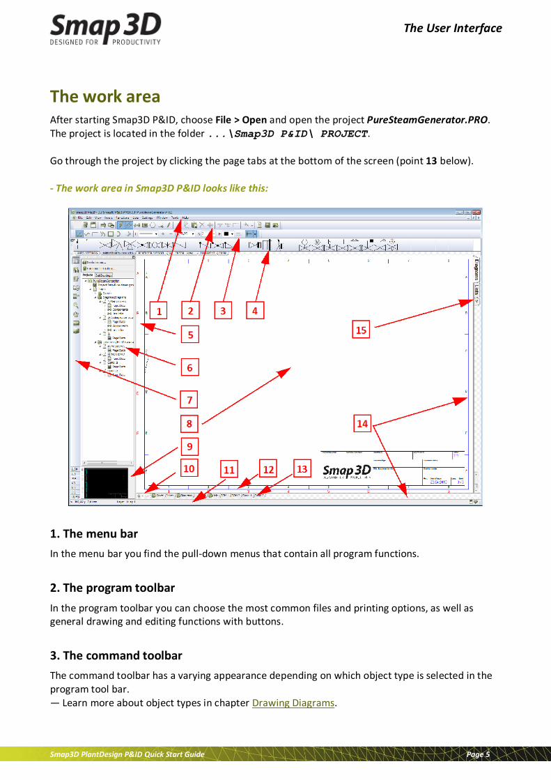
The work area After starting Smap3D P&ID, choose File > Open and open the project PureSteamGenerator.PRO. The project is located in the folder ...\Smap3D P&ID\ PROJECT. Go through the project by clicking the page tabs at the bottom of the screen (point 13 below). - The work area in Smap3D P&ID looks like this:
1. The menu bar In the menu bar you find the pull-down menus that contain all program functions.
2. The program toolbar In the program toolbar you can choose the most common files and printing options, as well as general drawing and editing functions with buttons.
3. The command toolbar The command toolbar has a varying appearance depending on which object type is selected in the program tool bar. — Learn more about object types in chapter Drawing Diagrams.

The User Interface
Smap3D PlantDesign P&ID Quick Start Guide Page 6
4. The pickmenu Here you place the symbols, line types, and text types you use the most (favorites), so that you can fetch them right away, and place directly in the diagram pages. By clicking on the tabs at the bottom of the pickmenu, you select which of the created pickmenus to display. — See Symbols.
5. The help frame The help frame is not enabled the first time you start the program. It displays the standard margin for the selected paper size. There is also a printer help frame, displaying your printer margins. Both help frames can be enabled\disabled easily.
6. The Explorer window The Explorer window contains the two tabs Projects and SubDrawings. Projects tab:
On the Projects tab you can get information about all open projects. You get a survey of the project pages, and a survey of all components on these pages. When you click on an object symbol for a project page, the page is displayed on the screen. SubDrawings tab:
The SubDrawings tab is applied for handling — e.g. placing, editing, and displaying — sub drawings and templates. For instance you can drag templates and sub drawings into the active project page, or create new sub drawings based on copied areas from the active project. — See How to insert new pages.
7. The left toolbar The left toolbar contains various page and zoom functions, and — at the bottom — information about the page settings and status.
8. The work area The work area on the screen corresponds to the size of paper you have chosen to work on. The size of the paper is specified in Settings > Page setup....
9. The survey window The survey window gives you a survey of the entire page. The part of the page that you currently see on the screen (the zoom), is represented by the black box. This black box can move by dragging it with left mouse button.

The User Interface
Smap3D PlantDesign P&ID Quick Start Guide Page 7
10. Page history buttons
By clicking on the Page history buttons , you can jump to the previously active pages in the project.
11. The status line Among others, you can see here coordinates, layer titles, guiding texts, as well as various messages. When you let the mouse pointer rest over for instance a button on the screen, an explanatory text (tool tip) will be displayed here.
12. Current path numbers Current path numbers are displayed in two different places: At the location you specify in your project, and on the lower part of the screen. When you zoom in on a part of a diagram, the current path numbers will still be displayed on the lower part of the screen. Thus you will always know where you are on the diagram.
13. Page tabs When you click on a chapter tab, you jump to the first page in the selected chapter. — See How to choose pages and chapters. Page tabs are automatically created in a project when templates with specific page function setting are used/inserted.
14. Scrollbars Having zoomed in on an area, you can move the area by dragging the scrollbars.
15. Chapter tabs When you click on a chapter tab, you jump to the first page in the selected chapter. — See How to choose pages and chapters.

The User Interface
Smap3D PlantDesign P&ID Quick Start Guide Page 8
Most important zoom functions
Middle mouse wheel When scroll middle mouse wheel (if available) the zoom factor in work area does change. • Scroll the mouse wheel forward, will enlarge (zoom in) the area where the cross hairs are
located.
• Scroll the mouse wheel backward, will scale down (zoom out) the area where the cross hairs are located.
You can change the behavior of scrolling the middle mouse wheel button between scroll and zoom by clicking on the pull-down menu Settings > Pointer/Screen and select the desired function under Mouse wheel.
Functions in left toolbar In the left toolbar there are zoom functions available as icons.
+ Zoom The function +Zoom will allow you to zoom into a selected rectangle area. This zoom area must defined with the mouse on the active page. To do this, click on the icon and drag a window around the area you wish to zoom into.
PAN This function PAN will allow you to move the active page free in all directions. For this you must press and hold the left mouse button while dragging the mouse. The zoom factor is NOT changed with this function.
Zoom to page (Home) This function Zoom to page (Home) will reset the actual view of the active page back to full screen. Per default, zoom to page will display the page in full screen. But if the user has defined a different user specific home view in menu View > Set User Home view, than the view will reset to this stored definition.

Projects and Pages
Smap3D PlantDesign P&ID Quick Start Guide Page 9
Projects and Pages With this chapter you get information to the following topics: What is a project?
How to insert new pages?

Projects and Pages
Smap3D PlantDesign P&ID Quick Start Guide Page 10
What is a Project?
What does Project oriented mean? Smap3D P&ID is a project oriented program. This means that all the information you need in connection with a PID project, is gathered in one single file (*.PRO). Therefore you do not need to change program when you e.g. want to generate lists, bill of material, or chapter divider because these are part of the same project file as the diagram drawings.
What does a project consist of? A project can typically contain a front page, table of content, chapter front pages, pages with diagrams, pages containing different types of lists, and a symbol documentation. All these parts are placed on their individual page/pages in the project.
Sample project
See a project example in the file PureSteamGenerator.PRO in the Smap3D P&ID\PROJECT folder. All explained page types are also included in this project.

Projects and Pages
Smap3D PlantDesign P&ID Quick Start Guide Page 11
The project drawing is the heart of the project The heart of your project is the project drawings. Here you draw the diagrams by placing symbols, lines, and texts on one or more diagram pages. Here you also attach article data to the individual symbols in the diagrams. This article data can be fetched from the component database and can then be transferred automatically to the project lists.
Symbol documentation
You can also generate Symbol documentation (symbol legends) automatically in a project: Get further details in the Smap3D P&ID Tools manual. In this manual you can also see how to translate project texts with the Translator program, and how to set up the parameters for DWG/DXF import and export.

Projects and Pages
Smap3D PlantDesign P&ID Quick Start Guide Page 12
How to insert new pages? There are many ways to insert new pages in Smap3D P&ID. Here is one of them:
How to drag a new page into a project?
1. Choose File > Open and open the project PureSteamGenerator.PRO (placed in folder ...\Smap3D P&ID\PROJECT).
2. Click the page tab for page 2 at the bottom of the screen to specify where you want to place the new project page:
3. In the Explorer window: Click the SubDrawings tab and click the Template folder. – Here you see all the page templates you can drag into the project. The templates are ordered in folders according to their function.
4. To insert a diagram page: Click the Normal folder and all templates containing empty diagram pages are displayed.
5. Click on the pages to check what they look like. A short description is also displayed.
6. Click on EN_Sheet A3 horizontal.STD, keeping the mouse button pressed down, drag the page into the project and release the mouse button.

Projects and Pages
Smap3D PlantDesign P&ID Quick Start Guide Page 13
7. The page is now inserted into the project. You can also insert a page by pressing the <Ctrl>, while clicking the desired page.
Choose the correct page type
If, for instance, you create a list on a diagram (function NORMAL), the list will not get data from your drawings automatically. For lists there are the page types Parts List and Components List.
How to choose pages and chapters? — Open the project ...\Smap3D P&ID\PROJECT\PureSteamGenerator.PRO. You can change back and forth between the project pages by clicking the tabs on the lower part of the screen.
When you click the chapter tabs in the right-hand side of the screen, the first page in the selected chapter is displayed. You can also use the [Page Up] and the [Page Down] keys to jump back and forth between project pages. Also, you can choose View > Go to page, and type in a page number.

Projects and Pages
Smap3D PlantDesign P&ID Quick Start Guide Page 14
How to move, copy, and delete pages? Below is just described one among many ways to move, delete, and copy pages.
How to move pages using the page tabs? 1. Select the page: Click the page tab for the page you want to move.
2. Click the page tab again, keep the mouse button pressed down, and drag the page to the
desired position. Release the mouse button. 3. Click OK to move the page. 4. If you have moved a chapter divider, you also are asked whether to move all pages in the
chapter.
Copy pages and chapters using the page tabs Pages and chapters are copied just like described above; the only difference is that you press the <Ctrl> key while doing it. When you copy pages/chapters, a small + is displayed in the cursor. When you copy pages, you are asked whether/how to rename the symbols on the page — and specify reference designations (if any).
Delete pages via the page tabs 1. Right-click the page tab. 2. Choose Delete.
Drawing Diagrams
Smap3D PlantDesign P&ID Quick Start Guide Page 15
Drawing Diagrams With this chapter you get information to the following topics: Drawing objects
Symbols
Components
Lines
Texts
Arcs/Circles
Lists
Drawing Diagrams
Smap3D PlantDesign P&ID Quick Start Guide Page 16
Drawing objects
What is a drawing object? In Smap3D P&ID there are four different types of drawing objects: Symbols, Texts, Lines and Circles. Any object you place in a drawing, will always be one of these four types of drawing objects. There is also the Area command, which makes it possible to work with all objects at the same time - e.g. when copying, deleting, moving or rotating objects.
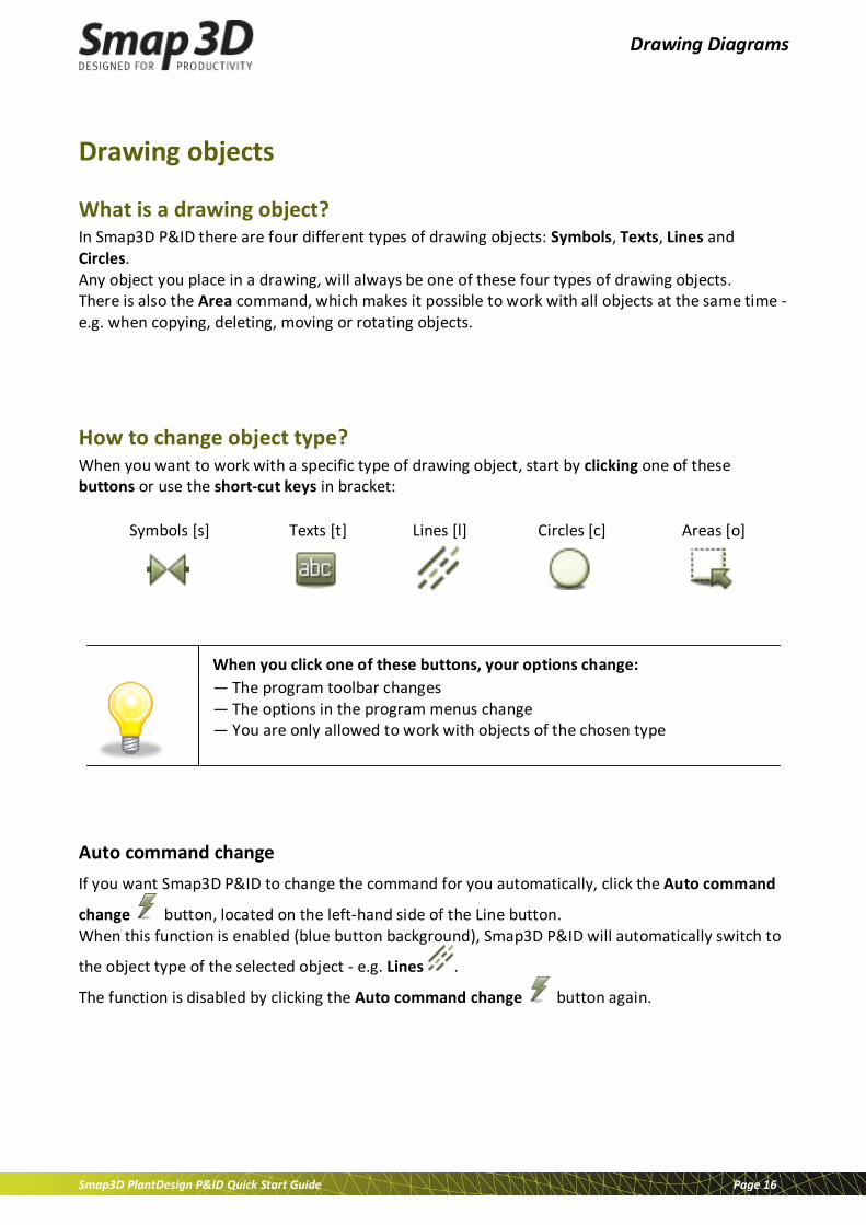
How to change object type? When you want to work with a specific type of drawing object, start by clicking one of these buttons or use the short-cut keys in bracket:
Symbols [s] Texts [t] Lines [l] Circles [c] Areas [o]
When you click one of these buttons, your options change:
— The program toolbar changes — The options in the program menus change — You are only allowed to work with objects of the chosen type
Auto command change If you want Smap3D P&ID to change the command for you automatically, click the Auto command
change button, located on the left-hand side of the Line button. When this function is enabled (blue button background), Smap3D P&ID will automatically switch to
the object type of the selected object - e.g. Lines .
The function is disabled by clicking the Auto command change button again.

Drawing Diagrams
Smap3D PlantDesign P&ID Quick Start Guide Page 17
How to work with drawing objects? In Smap3D P&ID there are two different modes to work in.
Which mode you work in is determined by the Draw button - also called the Pencil). You either:
a. Draw/place new objects (enabled/highlighted Pencil), or you work on
b. Already placed objects (disabled Pencil) - e.g. when moving, copying, deleting, or editing objects. The objects are selected by clicking them or by clicking and dragging the mouse over the selected objects. — See Selecting multiple objects.
Drawing Diagrams
Smap3D PlantDesign P&ID Quick Start Guide Page 18
Symbols In Smap3D P&ID you use symbols when you want to represent a specific procedural component or function in a diagram. When for instance you want to represent a vessel, you find the symbol for a vessel and place it in the diagram. Components with multiple functions can have more than one symbols attached – see Components.
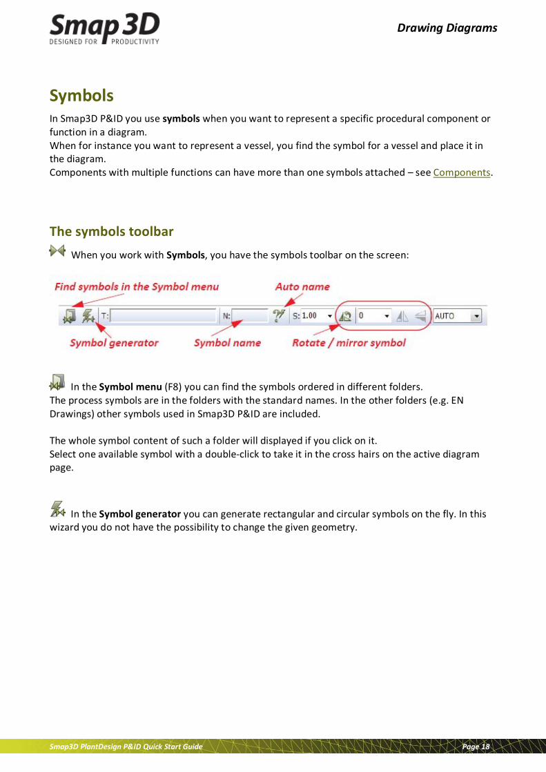
The symbols toolbar When you work with Symbols, you have the symbols toolbar on the screen:
In the Symbol menu (F8) you can find the symbols ordered in different folders. The process symbols are in the folders with the standard names. In the other folders (e.g. EN Drawings) other symbols used in Smap3D P&ID are included. The whole symbol content of such a folder will displayed if you click on it. Select one available symbol with a double-click to take it in the cross hairs on the active diagram page.
In the Symbol generator you can generate rectangular and circular symbols on the fly. In this wizard you do not have the possibility to change the given geometry.
Drawing Diagrams
Smap3D PlantDesign P&ID Quick Start Guide Page 19
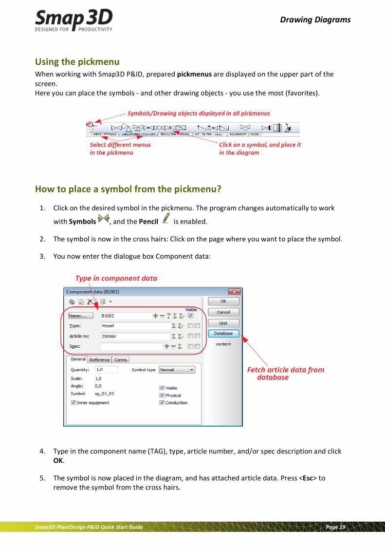
Using the pickmenu When working with Smap3D P&ID, prepared pickmenus are displayed on the upper part of the screen. Here you can place the symbols - and other drawing objects - you use the most (favorites).
How to place a symbol from the pickmenu?
1. Click on the desired symbol in the pickmenu. The program changes automatically to work
with Symbols , and the Pencil is enabled.
2. The symbol is now in the cross hairs: Click on the page where you want to place the symbol.
3. You now enter the dialogue box Component data:
4. Type in the component name (TAG), type, article number, and/or spec description and click OK.
5. The symbol is now placed in the diagram, and has attached article data. Press <Esc> to remove the symbol from the cross hairs.
Drawing Diagrams
Smap3D PlantDesign P&ID Quick Start Guide Page 20
Selecting components in the database via the pickmenu
1. Press <Ctrl> while clicking on a specific symbol in the pickmenu.
2. You enter the Database menu: Here you see all components in the database that contain this symbol.
3. Click on the desired component (database entry), click OK, and place the component symbol(s) on the page.
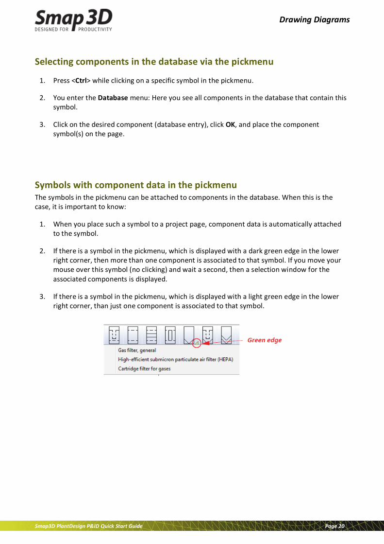
Symbols with component data in the pickmenu The symbols in the pickmenu can be attached to components in the database. When this is the case, it is important to know:
1. When you place such a symbol to a project page, component data is automatically attached to the symbol.
2. If there is a symbol in the pickmenu, which is displayed with a dark green edge in the lower right corner, then more than one component is associated to that symbol. If you move your mouse over this symbol (no clicking) and wait a second, then a selection window for the associated components is displayed.
3. If there is a symbol in the pickmenu, which is displayed with a light green edge in the lower right corner, than just one component is associated to that symbol.
Drawing Diagrams
Smap3D PlantDesign P&ID Quick Start Guide Page 21
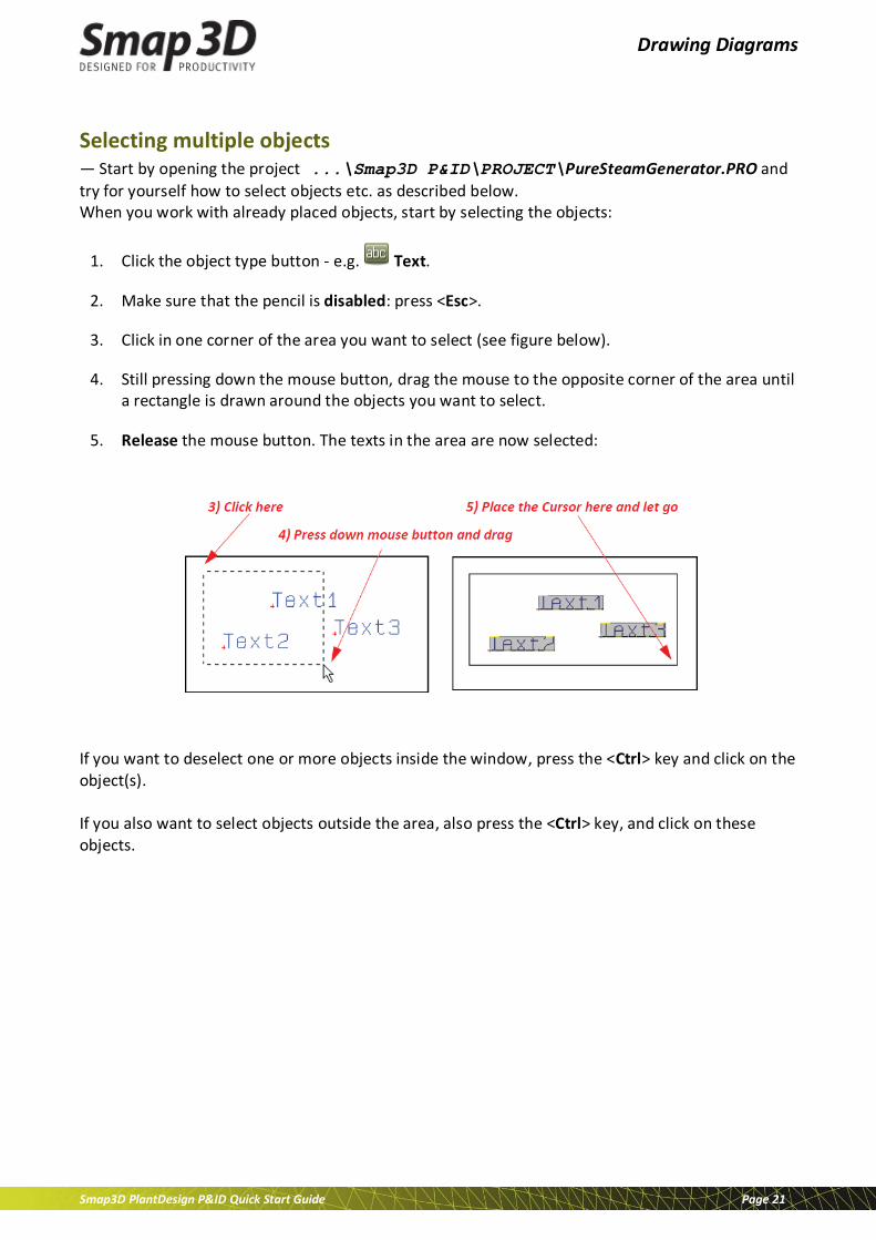
Selecting multiple objects — Start by opening the project ...\Smap3D P&ID\PROJECT\PureSteamGenerator.PRO and try for yourself how to select objects etc. as described below. When you work with already placed objects, start by selecting the objects:
1. Click the object type button - e.g. Text.
2. Make sure that the pencil is disabled: press <Esc>.
3. Click in one corner of the area you want to select (see figure below).
4. Still pressing down the mouse button, drag the mouse to the opposite corner of the area until a rectangle is drawn around the objects you want to select.
5. Release the mouse button. The texts in the area are now selected:
If you want to deselect one or more objects inside the window, press the <Ctrl> key and click on the object(s). If you also want to select objects outside the area, also press the <Ctrl> key, and click on these objects.
Drawing Diagrams
Smap3D PlantDesign P&ID Quick Start Guide Page 22
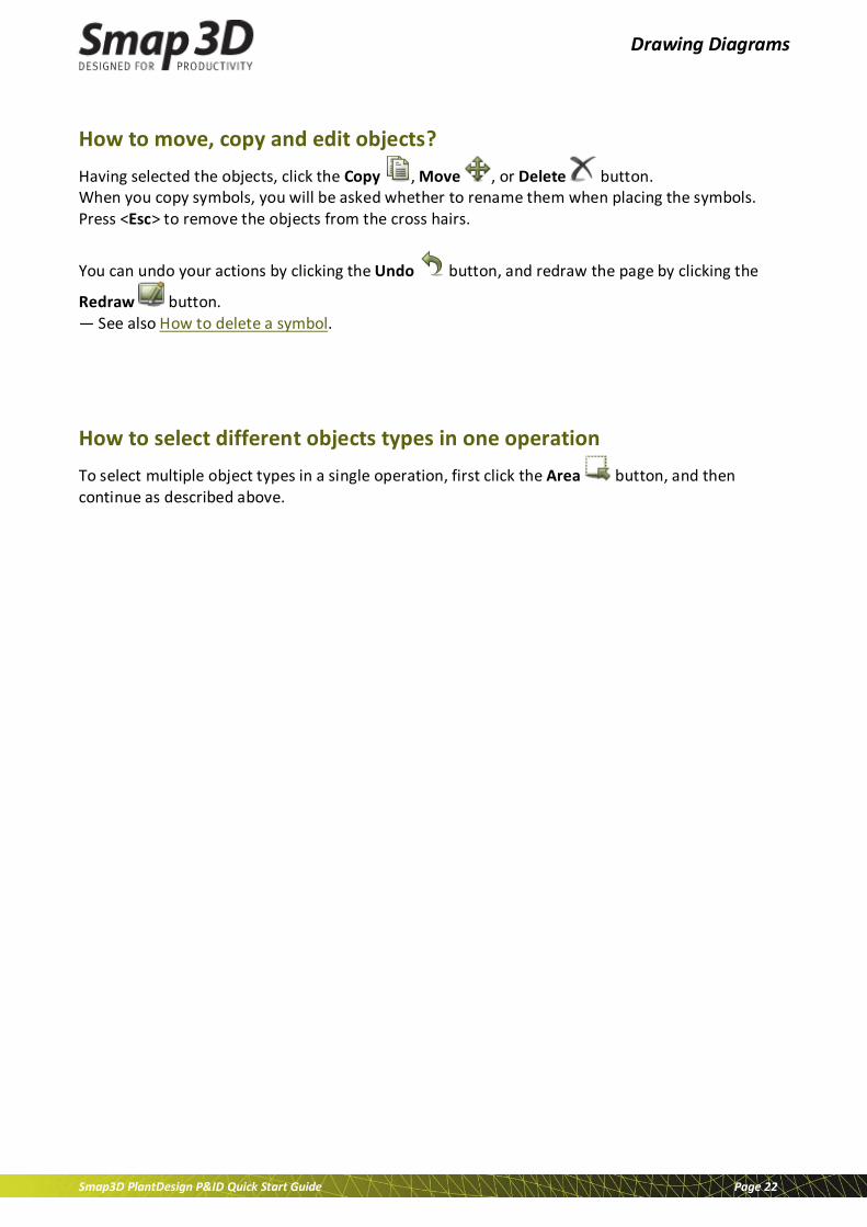
How to move, copy and edit objects? Having selected the objects, click the Copy , Move , or Delete button. When you copy symbols, you will be asked whether to rename them when placing the symbols. Press <Esc> to remove the objects from the cross hairs.
You can undo your actions by clicking the Undo button, and redraw the page by clicking the
Redraw button. — See also How to delete a symbol.
How to select different objects types in one operation To select multiple object types in a single operation, first click the Area button, and then continue as described above.

Drawing Diagrams
Smap3D PlantDesign P&ID Quick Start Guide Page 23
How to delete a symbol?
1. Click the Symbols button and press Esc> to disable the Pencil.
2. Click the Delete button and the dialogue box Delete is displayed:
3. You now have the following options:
o Click on Symbol: only the selected symbol is deleted.
o Click on Component: all symbols for the selected component are deleted (in the figure above you can see the component consist of 2 symbols).
o Click on Name: all symbols with this name (same TAG) are deleted (in the figure above you can see there are 4 symbols with this name in the project).
o Click on Cancel: No action is taken.
o — If you select Close lines, the lines are closed for all deleted symbols whenever this is possible (logical and geometry check). If you do not select Close lines, the lines are not closed (then they parked).
Drawing Diagrams
Smap3D PlantDesign P&ID Quick Start Guide Page 24
Components
The relationship between symbols and components
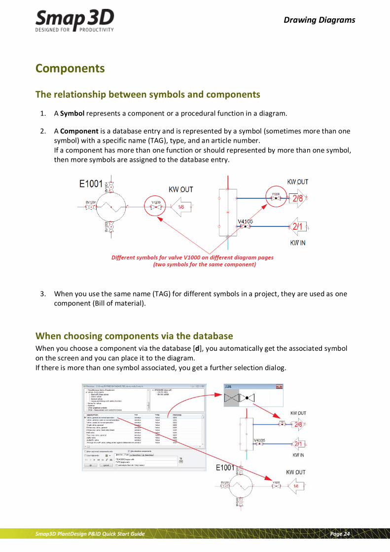
1. A Symbol represents a component or a procedural function in a diagram.
2. A Component is a database entry and is represented by a symbol (sometimes more than one symbol) with a specific name (TAG), type, and an article number. If a component has more than one function or should represented by more than one symbol, then more symbols are assigned to the database entry.
3. When you use the same name (TAG) for different symbols in a project, they are used as one component (Bill of material).
When choosing components via the database When you choose a component via the database [d], you automatically get the associated symbol on the screen and you can place it to the diagram. If there is more than one symbol associated, you get a further selection dialog.

Drawing Diagrams
Smap3D PlantDesign P&ID Quick Start Guide Page 25
Lines
Conducting and non conducting lines There are two different types of lines in Smap3D P&ID:
• Conducting lines (Pipelines)
• Non conducting / free lines
When Conducting lines is enabled/highlighted, the line will be understood as a connected line (pipeline). When it is disabled, the line will not be understood as a connected pipeline.
How to draw lines?
1. Click the Lines button or press the short-cut key [l].
2. The toolbar for lines is displayed:
3. To draw lines: click the Pencil to enable the line creation.
4. Select the drawing mode - e.g. Straight lines .
5. Click where you want to start with the line and click once at each position where you want to change the drawing direction of the line.

Drawing Diagrams
Smap3D PlantDesign P&ID Quick Start Guide Page 26
6. To stop drawing the line press <Esc> to disable the Pencil. Now the line is displayed with the appearance you have defined before the line was drawn. If there are any mistakes and you like to change the line appearance after the creation then you have to follow the next steps.
How to edit the line appearance after it was drawn?
1. Click on the line(s) that you would like to change the appearance of.
2. The toolbar for lines is displayed (it displays the last used settings, not the properties for the selected line(s).
3. To get/view the actual line properties for the selected line(s): click the Copy properties button.
4. Now the properties from the actual selected line(s) are displayed in the line toolbar.
5. Change the required line properties (e.g. line type, line width and line color) in the line toolbar.
6. To transfer these settings to the selected line(s): click the Transfer properties button.
7. To end this function, press <Esc>.
Drawing Diagrams
Smap3D PlantDesign P&ID Quick Start Guide Page 27
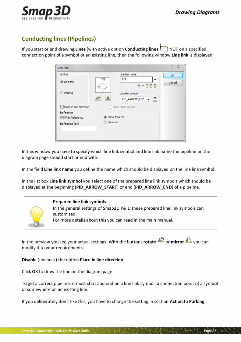
Conducting lines (Pipelines) If you start or end drawing Lines (with active option Conducting lines ) NOT on a specified connection point of a symbol or an existing line, then the following window Line link is displayed.
In this window you have to specify which line link symbol and line link name the pipeline on the diagram page should start or end with. In the field Line link name you define the name which should be displayed on the line link symbol. In the list box Line link symbol you select one of the prepared line link symbols which should be displayed at the beginning (PID_ARROW_START) or end (PID_ARROW_END) of a pipeline.
Prepared line link symbols
In the general settings of Smap3D P&ID these prepared line link symbols can customized. For more details about this you can read in the main manual.
In the preview you see your actual settings. With the buttons rotate or mirror you can modify it to your requirements. Disable (uncheck) the option Place in line direction. Click OK to draw the line on the diagram page. To get a correct pipeline, it must start and end on a line link symbol, a connection point of a symbol or somewhere on an existing line. If you deliberately don't like this, you have to change the setting in section Action to Parking.

Drawing Diagrams
Smap3D PlantDesign P&ID Quick Start Guide Page 28
Texts
How to place text?
1. Click the Texts button - or press short-cut key [t].
2. The toolbar for texts in mode free text is displayed:
3. Click in the text field, type in the text as displayed above and press <Enter>.
4. The text is now in the cross hairs. Click on the page where you want to place it.
How to edit a text
1. Click the Texts button and disable the Pencil by pressing <Esc>.
2. Double-click on the text.
3. Edit the text in the displayed window and press <Enter> - or click OK.

Drawing Diagrams
Smap3D PlantDesign P&ID Quick Start Guide Page 29
Text types in Smap3D P&ID There are various types of text in Smap3D P&ID:
Text type Description
Free texts Texts, that can be used anywhere in the project.
Symbol-texts Texts, that are attached to each symbol, containing information on the component that is represented by the symbol. (Name "TAG", Type, Article no. and Spec).
Connection point texts
Texts, that are attached to each of a symbols connection points. (Line number, Function, Size, Line size).
Datafields Text fields that are filled out automatically (e.g. title block).

Drawing Diagrams
Smap3D PlantDesign P&ID Quick Start Guide Page 30
Arcs/Circles The function for arcs or circles is available in the diagram environment as well as at the symbol creation (symbol environment). But usually arcs and circle function is just used to draw symbol geometry.
How to draw circles and arcs?
1. Click the Arcs/circles button or press the short-cut key [c].
2. The toolbar for circles is displayed. There you have these options:
3. To draw an arc or circle: click the Pencil to enable the creation and get it on your cross hairs.
4. Change the parameters for your required geometry - e.g. Start and end angle for an arc, and so on.
5. Click on the page where you want to place the center of the arc/circle.
6. To end this function, press <Esc> to disable the Pencil.

Drawing Diagrams
Smap3D PlantDesign P&ID Quick Start Guide Page 31
How to edit the circle/arc geometric and appearance after it was drawn?
1. Click on the arc(s)/circle(s) you like to change.
2. The toolbar for circles is displayed (display the last used settings, not the properties for the selected objects).
3. To get/view the actual settings for the selected objects: click the Copy properties button.
4. Now the actual properties are displayed in the circle toolbar:
5. Change the required arc/circle properties in this toolbar.
6. To transfer this setting to the selected circles/arcs: click the Transfer properties button.
7. To end this function, press <Esc>.

Drawing Diagrams
Smap3D PlantDesign P&ID Quick Start Guide Page 32
Lists
What is a list? In Smap3D P&ID there are different kinds of lists. Most common in P&ID schematic diagrams are: Parts lists and Components lists. To place a list in a project it must exist as a symbol or ideally as a template.
How to place list as page in a project?
1. Choose File > Open and open the project PureSteamGenerator.PRO (placed in folder ...\Smap3D P&ID\PROJECT).
2. Click the page tab for page BOM 2 at the bottom of the screen to specify where you want to place the new list page:
3. In the Explorer window: Click the SubDrawings tab and click the Template folder. – Here you see all the delivered page templates you can drag into the project. The templates are ordered in folders according to their function.
4. To insert a parts list page: Click the PartsList folder; all the available parts list templates are displayed.
5. Click on the pages to check what they look like. A short description is also displayed.
Drawing Diagrams
Smap3D PlantDesign P&ID Quick Start Guide Page 33
6. Click on EN_PartsList_PID.STD, keep the mouse button pressed down, drag the page into the project and release the mouse button.
7. The PartsList page is now inserted as an empty page in the project. You can also insert a page by pressing the <Ctrl> key while clicking the desired page.
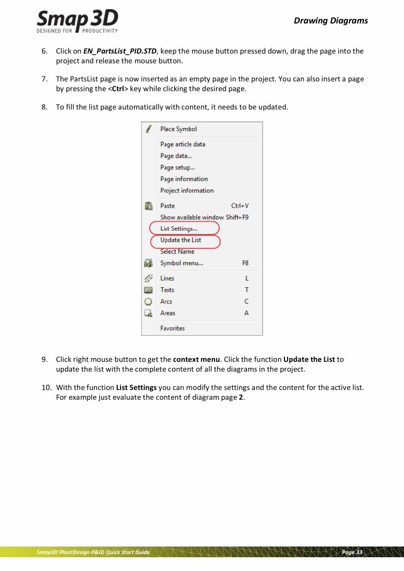
8. To fill the list page automatically with content, it needs to be updated.
9. Click right mouse button to get the context menu. Click the function Update the List to update the list with the complete content of all the diagrams in the project.
10. With the function List Settings you can modify the settings and the content for the active list. For example just evaluate the content of diagram page 2.
Advanced functions
Smap3D PlantDesign P&ID Quick Start Guide Page 34
Advanced functions With this chapter you get information to the following topics: Symbol reference
Line gaps
Insulation
Design check
Object Lister
Creation of custom symbols
Export PDF
Advanced functions
Smap3D PlantDesign P&ID Quick Start Guide Page 35
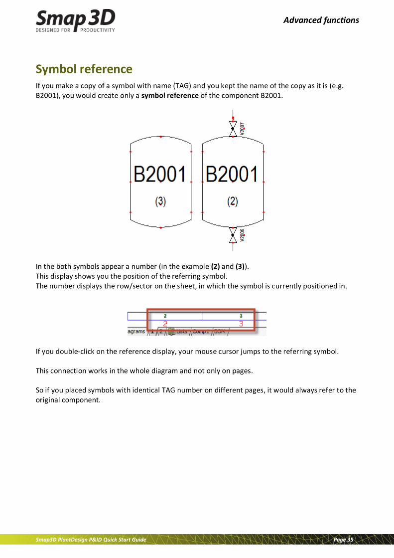
Symbol reference If you make a copy of a symbol with name (TAG) and you kept the name of the copy as it is (e.g. B2001), you would create only a symbol reference of the component B2001.
In the both symbols appear a number (in the example (2) and (3)). This display shows you the position of the referring symbol. The number displays the row/sector on the sheet, in which the symbol is currently positioned in.
If you double-click on the reference display, your mouse cursor jumps to the referring symbol. This connection works in the whole diagram and not only on pages. So if you placed symbols with identical TAG number on different pages, it would always refer to the original component.

Advanced functions
Smap3D PlantDesign P&ID Quick Start Guide Page 36
The style of the reference display can be changed in the Settings > Text/Symbol Defaults:

Advanced functions
Smap3D PlantDesign P&ID Quick Start Guide Page 37
Line gaps If you don’t like the default style of line crossing display you can change it. We have added new options since V10 to highlight pipeline intersections. Go to menu Settings > Pointer/Screen. On the bottom of the window you can make the changes:
The picture shows the different possible styles of intersections:
This setting is project related. That means, if you open a different project, you might have a different style set in this project.

Advanced functions
Smap3D PlantDesign P&ID Quick Start Guide Page 38
Insulation It is also possible to show insulation on the pipelines.
To do this, select an existing pipeline and click the copy properties button.
Next, activate the insulation button in the toolbar:
Click the Transfer properties button to write the changed settings to the line The result should look similar like in the picture.

Advanced functions
Smap3D PlantDesign P&ID Quick Start Guide Page 39
Design check Smap3D P&ID does have a tool which helps you to avoid mistakes in your P&ID diagram.
When using the Design check function in a project, you are notified about the most obvious drawing errors: Thus the design check function can support you, when you wish to check your design. We recommend to apply the design check function from time to time while you are drawing. This way you don’t have to bother with too many error messages later.
Performing a design check
Choose menu Functions > Design Check, or click the Design Check button.
In the Design Check dialog box click the Design Check settings button, to get the following options:
Select which errors you like to check the project for. To maintain the overview, we recommend to check the project just for one type of errors at a time.

Advanced functions
Smap3D PlantDesign P&ID Quick Start Guide Page 40
We do not recommend the following options: • If you select All design errors (recommended) at the bottom of the dialog box, all checks for
design errors are selected in the dialog box.
• If you select All warnings all checks are selected in the dialog box.

Advanced functions
Smap3D PlantDesign P&ID Quick Start Guide Page 41
Object Lister To navigate quickly in your projects, you can use the Object Lister (F7) function. The Object Lister makes it possible for you to locate any given component in a project and/or information about the applied symbols/components. In the Object Lister table you can also edit component data, page data, and free texts for all of the project. To enter the Object lister you choose menu Functions > Object Lister, or press the short-cut key <F7>. You can also click the Object Lister button in the upper part of the Explorer window, when you wish to enter the Object Lister. With the display of the Object Lister, the symbols tab will displayed as default. By choosing another object type (tab) at the top of the Object Lister, you determine whether to show Symbols, Line link, Texts, Reference frames, Pages or Lines (only lines with article data are displayed).
If you, as above, have chosen Symbols, all project symbols will appear in alphabetical order — independently of which page you are working on at present.
Advanced functions
Smap3D PlantDesign P&ID Quick Start Guide Page 42
Sorting order of data Initially the objects will be sorted by symbol name (page name and text contents respectively), but if you want them sorted by for instance article, click on the column heading Article. When you wish to see the objects in reverse order, click the column header again. The sorting order is alphabetical/numerical. You can sort all columns in both directions.
Selection of objects Selecting objects in the Object Lister follows the common Windows guidelines:
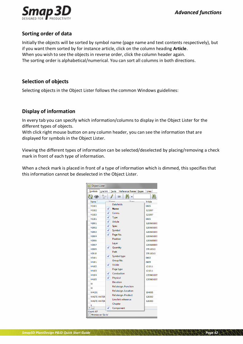
Display of information In every tab you can specify which information/columns to display in the Object Lister for the different types of objects. With click right mouse button on any column header, you can see the information that are displayed for symbols in the Object Lister. Viewing the different types of information can be selected/deselected by placing/removing a check mark in front of each type of information. When a check mark is placed in front of a type of information which is dimmed, this specifies that this information cannot be deselected in the Object Lister.

Advanced functions
Smap3D PlantDesign P&ID Quick Start Guide Page 43
Creating custom symbols Working with Smap3D P&ID, it might happen that the symbol folders do not contain the specific symbols you need. Therefore, this chapter is a guide on how to create your own symbols.
Creating a new Symbol In the following described example you can create a simple butterfly valve symbol. Furthermore, the symbol will contain a free text as well as two connection points. The precise meaning of this is follows later. To create a symbol, you have to be working in a project. If this is not the case you have to open a new project:
Click on the New document button, and leave the dialog box Settings by pressing <Esc> or by clicking on Cancel.
Click on the Symbols button, or use the short-cut [s]. Then click on the Symbol menu button. You can also press [F8] to enter the Symbol Menu directly.
In both cases it opens the window Symbol menu:
Click on the Select Library from Folders button or on the Select Library from Alias button, and select the folder/alias you wish to save the symbol under — e.g. the folder USER.

Advanced functions
Smap3D PlantDesign P&ID Quick Start Guide Page 44
Then click on the Create new symbol button, to create a new symbol. You now enter the Edit symbol mode, in which you can see SYMB flashing on a RED BACKGROUND in the lower part of the left tool bar.
Make an appropriate Zoom [z] around the red marks in the middle of the screen. On the middle of the screen, you will see the following drawn with the color red:
The symbol reference point The asterisk (*) is the reference point for the new symbol. This reference point is the inserting point (hangs on cross hairs), and the rotation point you rotate the symbol around, if you rotate it. A symbol has only got one reference point.
Reference points for symbol texts The red pluses (+) are the reference points for the symbol texts.
Position for references to other symbols When creating new symbols, you can furthermore specify the position for references to other symbols. The position of this reference point is pointed out in the lower-left corner in the figure above. The red plus for this reference text is always present in the Edit symbol mode, but does not become active for placed symbols before the symbol reference is activated, — e.g. symbols of the type Normal —, the reference is not displayed until you have selected With reference on the tab References in the dialog box Component data.

Advanced functions
Smap3D PlantDesign P&ID Quick Start Guide Page 45
Automatic creation of symbols
When you are in the Edit symbol mode (where you are now), you can also use the Symbol generator to create a “raw-symbol“ (rectangular or circular), which you can then continue working on here. To do this, choose Symbols, click the Symbol menu button, and click on the Symbol generator button.
Moving the reference point To make room to draw the symbol itself, you can now move the reference point a bit to the left.
Therefore, click on the Reference point button. Click on the reference point and drag it to a position you want. — In this sample you move it 15mm to the left. See the coordinates in the lower-left corner of the screen.
Lines in symbols
Click on the Lines button [l], and click on the Draw button (in order to make it highlighted). You can determine that lines in the symbol must follow the width and the color of the conducting lines, which gets connected to the symbol, when you are using it on a diagram later on.
If the Follow connected button is not enabled (highlighted), then click on it.
Drawing lines as a rectangle
To draw the rectangle in the symbol, you now click on the Rectangle button. Point out the lower-left corner of the rectangle by clicking on a point 5mm below and 10mm to the left of the reference point. Then point out the upper-right corner of the rectangle by clicking on a point 5mm above and 10mm to the right of the reference point. You have now drawn a rectangle of 20x10mm around the reference point. Coordinates and distances are displayed in the lower-left corner of the screen.
Advanced functions
Smap3D PlantDesign P&ID Quick Start Guide Page 46
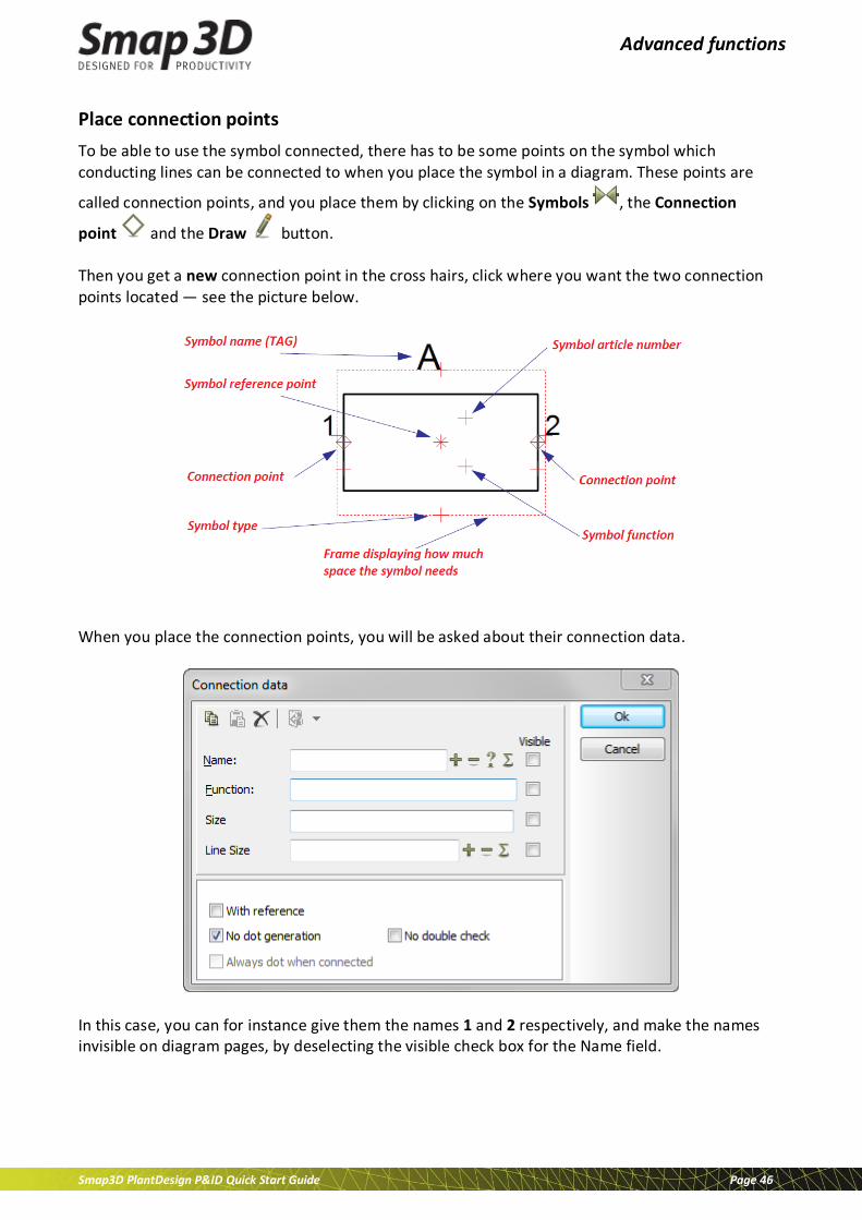
Place connection points To be able to use the symbol connected, there has to be some points on the symbol which conducting lines can be connected to when you place the symbol in a diagram. These points are
called connection points, and you place them by clicking on the Symbols , the Connection
point and the Draw button. Then you get a new connection point in the cross hairs, click where you want the two connection points located — see the picture below.
When you place the connection points, you will be asked about their connection data.
In this case, you can for instance give them the names 1 and 2 respectively, and make the names invisible on diagram pages, by deselecting the visible check box for the Name field.
Advanced functions
Smap3D PlantDesign P&ID Quick Start Guide Page 47
More options in the dialog box Connection data
With reference If you click here, an independent reference text is created for the connection point, which refers to connection points on symbols with the same name and connection name. — No check is required.
No dot generation — Set a check in the box.
No double check When performing a design check it is possible to examine whether the project contains symbols, which has more than one connection point with the same name. This is done by selecting Used more than once. — No check is required
You have now placed the connection points for the symbol. Press <Esc> to get rid of the connection point symbol in the cross hairs.
Drawing a slanted line
You draw a slanted line for the butterfly valve by clicking on the Line and the Draw button (short-cut [l]).
In the drawing mode you have to select Slanted lines button. Now you can draw a line from the upper left to the lower right corner of the rectangle.
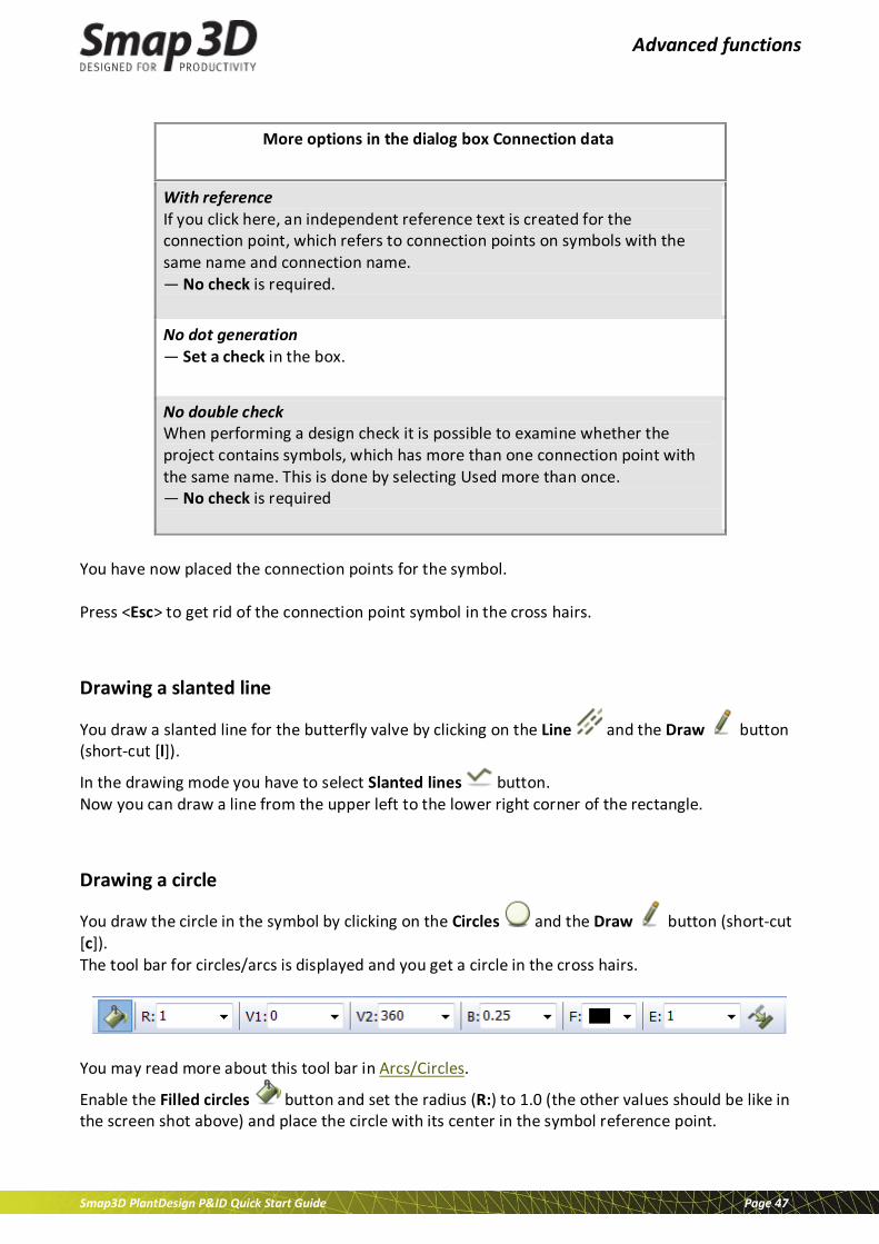
Drawing a circle
You draw the circle in the symbol by clicking on the Circles and the Draw button (short-cut [c]). The tool bar for circles/arcs is displayed and you get a circle in the cross hairs.
You may read more about this tool bar in Arcs/Circles.
Enable the Filled circles button and set the radius (R:) to 1.0 (the other values should be like in the screen shot above) and place the circle with its center in the symbol reference point.
Advanced functions
Smap3D PlantDesign P&ID Quick Start Guide Page 48
Typing in a free text Below the symbol, the free text Butterfly valve shall appear. — See Texts for further details.
Therefore click on the Texts button, or press the short-cut key [t]. Click in the text field in the texts tool bar, and type in the text Butterfly valve. Press <Enter>.
You now have the text in the cross hairs.
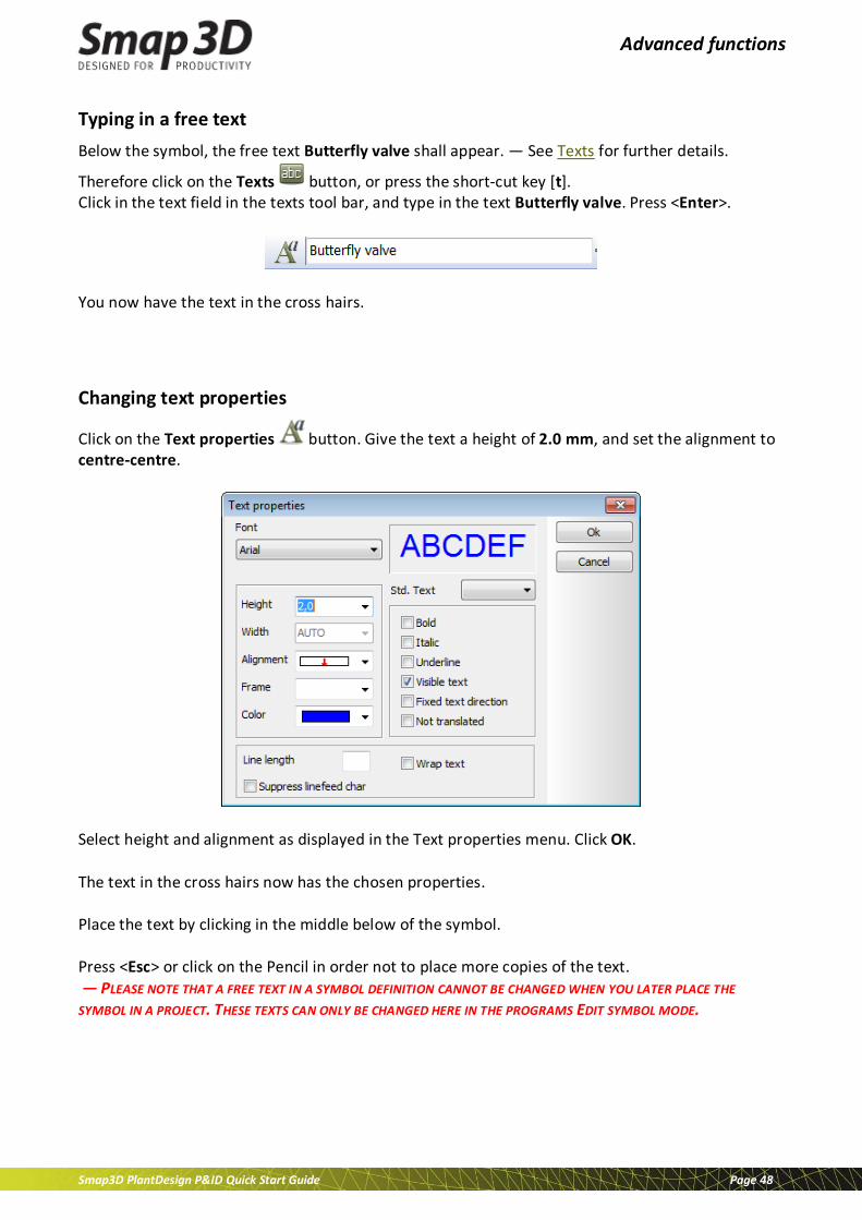
Changing text properties
Click on the Text properties button. Give the text a height of 2.0 mm, and set the alignment to centre-centre.
Select height and alignment as displayed in the Text properties menu. Click OK. The text in the cross hairs now has the chosen properties. Place the text by clicking in the middle below of the symbol. Press <Esc> or click on the Pencil in order not to place more copies of the text. — PLEASE NOTE THAT A FREE TEXT IN A SYMBOL DEFINITION CANNOT BE CHANGED WHEN YOU LATER PLACE THE SYMBOL IN A PROJECT. THESE TEXTS CAN ONLY BE CHANGED HERE IN THE PROGRAMS EDIT SYMBOL MODE.
Advanced functions
Smap3D PlantDesign P&ID Quick Start Guide Page 49
Texts and text properties for symbol texts
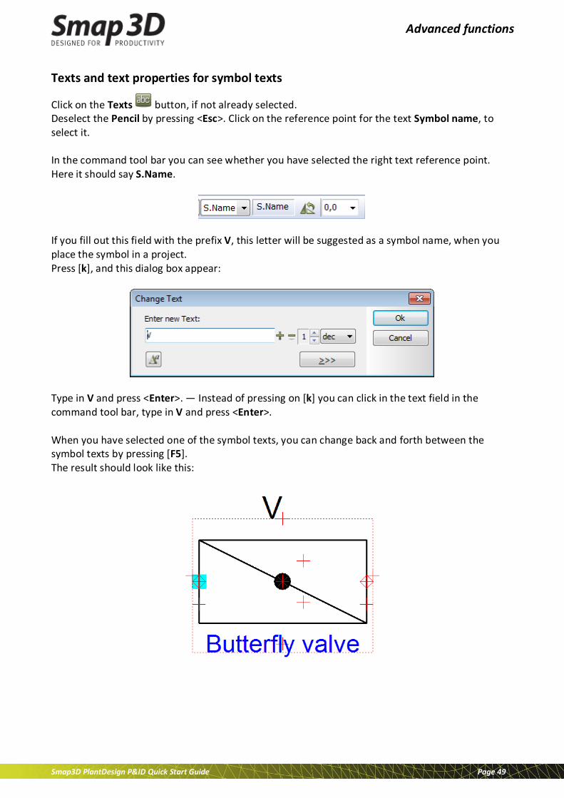
Click on the Texts button, if not already selected. Deselect the Pencil by pressing <Esc>. Click on the reference point for the text Symbol name, to select it. In the command tool bar you can see whether you have selected the right text reference point. Here it should say S.Name.
If you fill out this field with the prefix V, this letter will be suggested as a symbol name, when you place the symbol in a project. Press [k], and this dialog box appear:
Type in V and press <Enter>. — Instead of pressing on [k] you can click in the text field in the command tool bar, type in V and press <Enter>. When you have selected one of the symbol texts, you can change back and forth between the symbol texts by pressing [F5]. The result should look like this:

Advanced functions
Smap3D PlantDesign P&ID Quick Start Guide Page 50
Saving the symbol
Click on the Save button. If you have not saved the symbol before, a dialog box for Symbol settings will appear.
Give the symbol a Title — this means a description of the use or appearance of the symbol. This text will be displayed in the upper part of the Symbol menu when the symbol is selected there — and you also use it to determine which symbol to pick when you choose symbols in the pickmenu. Click inside the field, and type in for instance Butterfly valve with two connection points. The symbol in this example has no specific directions, so the symbol type is Normal. The Selection shall be set to Whole symbol. This means that the symbol will be selected if you click anywhere on the symbol. Click on OK.
The Symbol settings button
You can also enter this dialog box while designing the symbol if you click on the
Symbols and then on the Symbol settings button.
First time you save a symbol you enter the Save as dialog box. Here you select the folder you want to save the symbol in, like you normally do in Windows. Click in the File name field and type in the name Butterfly valve. The symbol will automatically get the extension .sym.
Click on Save . The symbol has now been saved.
Advanced functions
Smap3D PlantDesign P&ID Quick Start Guide Page 51
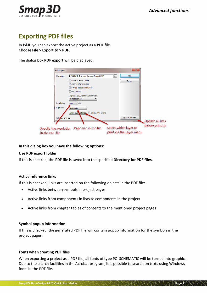
Exporting PDF files In P&ID you can export the active project as a PDF file. Choose File > Export to > PDF. The dialog box PDF export will be displayed:
In this dialog box you have the following options:
Use PDF export folder If this is checked, the PDF file is saved into the specified Directory for PDF files. Active reference links If this is checked, links are inserted on the following objects in the PDF file:
• Active links between symbols in project pages
• Active links from components in lists to components in the project
• Active links from chapter tables of contents to the mentioned project pages
Symbol popup information If this is checked, the generated PDF file will contain popup information for the symbols in the project pages. Fonts when creating PDF files When exporting a project as a PDF file, all fonts of type PC|SCHEMATIC will be turned into graphics. Due to the search facilities in the Acrobat program, it is possible to search on texts using Windows fonts in the PDF file.

Short-cut keys
Smap3D PlantDesign P&ID Quick Start Guide Page 52
Short-cut keys In Smap3D P&ID you will find most commands accessible through short-cut keys. It is also possible to define your own short-cut keys in the program. To do this, choose Settings > Pointer/screen > Shortcut.
Function Short-cut Key Function Short-cut Key
Areas [a] Print [Ctrl+p]
Circles / Arcs [c] Redraw [Ctrl+g]
Component Grouping
[Ctrl+F7] Replace [Ctrl+h]
Coordinates [Ctrl+ i] Replace symbol [F4]
Copy [Ctrl+c] Rotate 90° [spacebar]
Database [d] Save project [Ctrl+s]
Delete <Del> Select all [Ctrl+a]
Draw on/off <Insert> Show available [F9]
Elevation on/off [F11] Show available again
[Ctrl+F9]
Find [Ctrl+f] Slanted lines [Ctrl+k]
Find Article [n] Snap, fine <Shift>
Find next [F3] Straight lines [Ctrl+r]
Find Type [v] Survey window on/off
[F12]
Insert Potential [p] Symbol menu [F8]
Keyboard entry [k] Symbols [s]
Lines [l] Texts [t]
Next [F5] Undo [Ctrl+z]
Next page <PageDown> View article data [Ctrl+F2]
New document [Ctrl+n] View conducting [Shift+F2]

Short-cut keys
Smap3D PlantDesign P&ID Quick Start Guide Page 53
Object lister [F7] Write text [k]
On-line Manual [F1] Zoom [z]
Open [Ctrl+o] Zoom in [Ctrl+Home]
Preceding [F6] Zoom, move / Pan <Ctrl>+Arrow keys
Previous page <PageUp> Zoom out [Ctrl+End]
Previous selected page
[F10] Zoom to page <Home>
The short-cut keys Please note that using lower or upper case letters effects the short-cut function. Thus [Shift+c] will not enable the circles command. Whether <CapsLock> is enabled makes no difference.
Right-clicking To get further functions/options when working with the program, use right-click. For example you can right-click on a symbol, a line, a text, a circle, the pickmenu, or on the entire page. Right-clicking in many cases causes a menu to appear, a menu containing functions and/or data dealing with whatever you are clicking on. When in doubt, you can always try right-clicking.

Short-cut keys
Smap3D PlantDesign P&ID Quick Start Guide Page 54
CAD Partner GmbH Am Marktplatz 7 93152 Nittendorf Germany Phone: +49 9404 9639-21 Fax: +49 9404 5209 [email protected] www.Smap3D-Plant-design.com © 2014 CAD Partner GmbH. All rights reserved. This document is protected by copyright. The content of this document is furnished for informational use only, is subject to change without notice and should not be construed as a commitment by CAD Partner GmbH. Information in this document has been carefully checked; CAD Partner GmbH assumes no responsibility or liability for any errors or inaccuracies that may appear in the informational content. Smap3D is a Trademark of CAD Partner GmbH. All other names, registered trademarks and product names are used herein are the property of their respective holders.