version 12.0815 series - tomcat equipment · ˜ checking battery electrolyte level and confirm...
TRANSCRIPT

OP
ER
ATO
RS
MA
NU
AL
Version 12.0815
SERIES
RPS CorporationMailing: P.O. Box 368 Racine, WI. 53401Shipping: 1711 South Street Racine, WI. 53404
Phone: 1-800-634-4060Fax: 1-866-901-3335

This Manual Contains the Following Sections:
Table of Contents: Tells you where to look in the manual.
Machine Delivery Form: Should be filled out upon machine installation and faxed to 1-866-632-6961 or online
at www.rpscorporation.com.
Warranty Policy: Tells you coverage, exclusions and limitations to warranty.
Safety: Section contains important information regarding hazard or unsafe practices of the machine. Levels of
hazards are identified that could result in product or personal injury, or severe injury resulting in death.
Machine Controls: Shows you the different machine controls and features.
Machine Setup: Tells you how to setup machine from uncrating to installing squeegee and brushes.
Operations: Section is to familiarize the operator with the operation and function of the machine.
Battery Charging: Shows you how to charge the batteries (on-board and off board charging).
Maintenance: This section contains preventative maintenance to keep the machine and it's components in
good working condition. They are listed in this general order:
- Batteries - Scrub Brushes - Adjusting Squeegee - Service Schedule - Machine Trouble Shooting
Trouble Shooting: A list of common problems that
may occur.
Note: The serial number of your machine is located on
the lower half of the steering column on the machine (see picture to your right).
* As Our Policy Is One Of Constant Improvement, All Information And* *Specifications Are Subject To Change Without Notice*
t
on

TOCTABLE OF CONTENTS
Safety Information----------6Safety Information----------7
Common Wear Parts----------8LCD Screen Menu Displays----------9
Controls and Functions----------10Controls and Functions----------11
Uncrating Machine/Connecting Batteries----------12Squeegee Attachment/Removal----------13
Squeegee Adjustment----------14Leveling Scrubdecks----------15
Attaching Disk Brushes/Pads----------16Adjusting Shrouds----------17
Adjusting Cylindrical Side Wipers----------18Tip Back Tank/Solution System----------19
Vac System----------20Vac Filter Box----------21
Machine Operation----------22Machine Operation----------23Machine Operation----------24
Recovery Tank----------25Standard Battery Charging----------26Optional Battery Charging----------27
Onboard Charger Manual----------28Onboard Charger Manual----------29Onboard Charger Manual----------30
Changing Batteries----------31Side Broom System----------32
Machine Options----------33Machine Options----------34Machine Options----------35
Maintenance----------36Service Schedule----------37
Preventive Maintenance----------38Preventive Maintenance----------39
Troubleshooting - Central Command----------40Troubleshooting - Central Command----------41
Troubleshooting - ERROR Codes----------42Troubleshooting - ERROR Codes----------43
Troubleshooting - Machine----------44Troubleshooting - Machine----------45Battery Maintenance Guide----------46
Soap Options----------47Soap Options----------48

1-800-634-4060 Machine Install / Warranty Registration www.rpscorporation.com
Installing Dealer: Installed By:
Location: (City, State): Install Date:
End-User Company Name End-User Contact:
Address: City/State: Zip
Phone: Fax: Email:
Model: Serial #: Hour Meter:
BUYER’S REPRESENTATIVE HAS RECEIVED INSTRUCTION IN PROPER OPERATION OF THE FOLLOWING CONTROLS AND FEATURES:
SCRUBBERS
� Filling solution tank, Solution tank sight tube, Solution drain hose or valve for flushing and freezing conditions
� Adjusting controls & operation, Double scrubbing, Squeegee lift delay, vacuum switch (horn honking) and vacuum timer
� Recovery tank draining & cleaning, vacuum screen removal and cleaning, drain saver basket emptied.
� Shroud and pad/brush removal and installation
� Side Wiper and Curtain adjustment and maintenance for water control
� Solution valve and filter operation (removal and cleaning)
� LCD display operation, 4 hour meters (key switch, brush, traction drive, vacuum)
� Tank tilt back feature, only when both tanks are fully drained
� Squeegee hose removal and checking for clogs
BURNISHERS
� Train and have customer demonstrate proper removal and replacement of burnishing pad
� Pad pressure gauge and proper operating range to avoid tripping the circuit breaker
SWEEPERS
� Demonstrate proper removal and replacement of main broom and side brooms
� Method for cleaning the dust filter, empting out the debris hopper and correct installation
� Correct operation of the main broom and side broom levers, and understands to park with brushes in UP position
� Trained on the “Wet-Sweep” bypass door and not to operate through standing water
EDGE MACHINES
� EDGE scrubbers must have their isolators & deck hour meter replaced every 250 hours of use.
� Customer understands the Grip Face is not warranted against damage from improper use or direct contact with the floor
ALL MACHINES
� Checking battery electrolyte level and confirm monthly check that battery terminals are tight
� Parking brake override
� Charging operation and customer understands batteries have limited “cycles” and recharging = 1 cycle
� Seat and steering wheel adjustment
� Customer has read and understands the list of WARNINGS in the Operator manual
� Battery and Machine Maintenance Guide posters hung up and reviewed
� Manufacturer’s website is a good source of information and sign up for quarterly newsletters
In addition to the above items the buyers representative has received the operator’s manual and been advised to read the manual before operating the machine.
Installed By (print) Signature
Buyers Representative (print) Signature
Buyer agrees to pay for any repairs, adjustments, or secondary training that manufacturer determines is excluded from the warranty.
Complete and Fax Form to 1-866-632-6961 or online www.rpscorporation.com

STANDARD WARRANTY POLICY (RPS Corporati on)RPS Corporati on warrants its machines, parts and accessories to be free of manufacturer’s defects for the periods specifi ed below. Warranty will be granted at the sole discreti on of RPS Corporati on and is subject to fi nal claim and parts review by R.P.S. Corporati on and its vendors. This policy is eff ecti ve January 1, 2010 and is subject to change on producti on units at a future date.
COVERAGE, EXCLUSIONS AND LIMITATIONS:
Coverage: All (non-fl oor machines) Models sold (Sweepers, Scrubbers, Burnishers)
Parts: 36 months / 1,500 hours on “Power On” hour meter
Labor: 12 months
Travel: 3 months (150 mile maximum)
Poly Tanks: 7 Years (Water must not exceed 135°F/57°C
OEM Parts: 3 months
Validity: Fully completed Machine Delivery Form (online or fax) is on record at RPS.
Limitati on: Warranty will begin on date of machine installati on to end-user or 6 months aft er shipment from RPS Corp to the distributor if unsold at that ti me.
This warranty includes all parts on the machine except normal wear parts. Some of these excepti ons are:
Edge isolators (250 hours on average)
Squeegee Blades, Wiper Blades, Skirts and Curtains.
Caster Wheels, Squeegee Wheels and Bumpers.
Lights (Strobe, Headlights, or Bulbs).
Chains and Belts.
Filters, Screens, and Vacuum Bags.
Motor Brushes and commutater wear.
Brooms, Brushes, Pads and Pad Retainers.
Hoses and Tubing.
Drive Tires, Pneumati c Wheels and Tubes.
Rubber Floor Seals and Gaskets.
Vacuum motors with evidence of moisture or debris intrusion or > 400 hours.
The Batt eries (see below).
NOT COVERED: Routi ne maintenance, adjustments or parts damaged from abuse, neglect, improper use of the machine, or lack of scheduled “daily, weekly, monthly” maintenance in accordance with our published PM Sheets.
POLY TANKS: 7 Years Coverage against leakage due to manufacturer’s defect in materials or workmanship. Tank warranty void if water used exceeds 135°F/57°C
NOTE: Freight coverage for 3-Years under the parts secti on of warranty.
BATTERIES: Warranted through batt ery manufacturer for One (1) Year (prorated) from the date of delivery. The batt ery manufacturer ap-proves or denies the warranty coverage aft er analysis. We rely on solely on their review.
NOTE NOT COVERED: Damage from lack of water, failure to use OEM charger, or non-disti lled water.
Batt ery terminals – Batt ery terminals and cable connecti ons are covered for 30 days from the shipment of the machine. (Batt ery terminals ti ghtness should be inspected every 30 days.)

XR Operators Manual V12.0815
6
6 of 49
Safety Messages:
Your safety, and the safety of others, is very important, and operating this unit safely is an important responsibility.
To help you make informed decisions about safety, we have provided operating procedures and other safety information in the manual. This information informs you of potential hazards that could hurt you or others.
It is not practical or possible to warn you of all the hazards associated with operating this unit. You must use your own good judgment.
This machine is intended for commercial use. It is designed to be used on hard floor in an indoor environment with the recommended pads or brushes.
1. DO NOT OPERATE UNIT: Unless trained and authorized
Unless operator manual is read and understood
If unit is not in proper operating condition
With water that exceeds 135°F/57°C
With high percentage bleach mixture
Outdoors or exposed to rain
For picking up hazardous materials/dust
On surfaces having a gradient exceeding 2%
Parking brake is functioning on the machine
2. WHEN OPERATING UNIT: Remove loose objects from the floor that may be projected from the revolving brushes
Keeps hands and feet away from the revolving brushes
Do not operate machine where flammable liquids are present
Use extreme caution when maneuvering
3. BEFORE LEAVING: Drain Tanks
Make sure machine is turned off
Stop on level surfaces
Disconnect batteries
4. BEFORE SERVICING: Stop on level surface and secure machine
Disconnect batteries
5. BEFORE DISCARDING MACHINE: The batteries must be removed and properly disposed of
Safety Information

7 of 49XR Operators Manual V12.0815
7!! Safety Precautions !! WARNING!: Hazardous voltage. Shock, burns or
electrocution can result. Always disconnect the batteries before servicing machine.
WARNING!: Batteries emit hydrogen gases.
Explosion or fire can result. Keep sparks and open flames away.
WARNING!: Charge unit in a well ventilated area,
and keep battery compartment open when charging. Explosion or fire could result.
WARNING!: Battery acid can cause burns. Wear
protective eye wear and gloves when servicing batteries.
WARNING!: Do not store outdoor or pressure
wash. Prevent electronic components from getting wet.
WARNING!: The use of parts and solutions other
than that recommended by the manufacturer may cause damage or endanger people.
WARNING!: Dress safely. Do not wear rings or
metal wrist watches while working on this machine. They can cause an electrical short, which can cause serious burns. Do not work on this machine while wearing a tie, scarf or other loose, dangling neckwear or clothing. These loose items can tangle in the rotating parts and cause serious injury or even death.
WARNING!: Do not use the machine as a step
ladder or chair.
WARNING!: Only operate this machine from the
operators position. It was not designed to carry passengers.
WARNING!: Do not operate this machine on
ramps or uneven surfaces. When climbing a ramp, always drive the machine forward, straight up or down the ramp. Never drive across the incline. Do not back down or turn on ramps!
WARNING!: Do not use a high percentage bleach
mixture.
WARNING!: Always use the charger provided by
the manufacturer to charge the machine. It is an automatic charger, specifically designed to charge at the appropriate rate. If you must use a different charger, disconnect the batteries before charging. This will prevent damage to the electronic speed controller.
WARNING!: Understand the dynamic braking
system before you operate the machine on ramps. Machine may coast.
WARNING!: Do not park the machine on ramps or
slopes.
WARNING!: Do not operate the machine if any
parts have been removed or damaged.
WARNING!: Do not remove, paint over, or destroy
warning decals. If warning decals become damaged, they must be replaced.
WARNING!: Do not operate machine in unsafe
conditions. If the machine is in need or repair or is in anyway unsafe to operate, the matter should be reported immediately to the shift supervisor. Do not operate the machine until it is returned to proper operating condition.
WARNING!: This machine must only be operated
by a trained operator. As part of his or her training, they must read this manual thoroughly. If extra copies are needed, contact your local dealer.
WARNING!: Always turn off the machine before
leaving it unattended.
WARNING!: Do not operate over electrical floor
outlets. May result in serious injury.
WARNING!: Do not use water that exceeds
135°F/57°C, may result in damage to tanks.
Safety Information

XR Operators Manual V12.0815
8
8 of 49
Common Wear Parts
Brushes Model34" Disk
Model40" Disk
Model46" Disk
Super Grit 17-421 SS 20-421 SS 23-421 SSTough Grit 17-421 S 20-421 S 23-421 SSMidi Grit 17-421 C 20-421 C 23-421 CLight Grit 17-421 PS 20-421 PS 23-421 PSPoly (.028) 17-421 P 20-421 P 23-421 P
Nylon (.016) 17-421 N 20-421 N 23-421 NTampico 17-421 T 20-421 T 23-421 T
Pad Driver 17-421 D 20-421 D 23-421 DDiamond
Driver17-421 DD 20-421 DD 23-421 DD
Brush Repair Kit: 40-423 Replacement locating clip for all brushes
NOTE: # In Disk column denotes pad size: 17, 20, 23
Pads Disk Level ColorSuper Black ##-422 BB Very High Black
Black ##-422 B High BlackBrown ##-422 BR High BrownGreen ##-422 G Medium GreenBlue ##-422 BL Moderate BlueRed ##-422 R Moderate Red
White ##-422 W Light WhiteExtra pad driver retaining clip: 40-433
Brushes Model34" Cyl
Model40" Cyl
Model46" Cyl
Super Grit N/A N/A N/ATough Grit 327-821 S 387-821 S 447-821 SMidi Grit 327-821 C 387-821 C 447-821 CLight Grit 327-821 PS 387-821 PS 447-821 PSPoly (.028) N/A N/A N/A
Nylon (.016) 327-821 N 387-821 N 447-821 N
Squeegee Size 34" Disk34" Cyl
40" Disk40" Cyl
46" Disk46" Cyl
Gum Rubber
Blade Kit
Linatex Blade Kit
Urethane Blade Kit
Complete Squeegee
Assemblies46" Squeegee Standard N/A N/A 360-770G 360-770L 360-770U 360-718053" Squeegee Optional Standard Optional 370-770G 370-770L 370-770U 370-718060" Squeegee Optional Optional Standard 380-770G 380-770L 380-770U 380-7180
NOTE: Squeegee blade kits include (1) Rear blade, (1) Front blade, and (2) Backup wheels with hardware.NOTE: Squeegee assemblies (complete) listed above all come with Linatex blades.NOTE: Size is stamped into the top of the painted steel squeegee body on all squeegee's.NOTE: The squeegee is designed for narrow aisles and may not have the same water control around tight turns as the larger squeegees.
SOAP:Citrus GreenLow pH DegreaserEco Neutral CleanerHigh Power DegreaserGlossHD Degreaser
For More SOAP Information call PowerCat (414) 745-9337www.powercatsolutions.com

9 of 49XR Operators Manual V12.0815
9LCD Screen Menu Displays:
Screen #1 (Operator)
Screen #2 (Maintenance)
Screen #3 (W/ Error Code)
*** Use Green Menu Selection Button on Control Panel to Change Screens ***
1. Battery Level Indicator - Indicates the energy level remaining in the batteries. (Shown on all menu displays)
2. Scrubdeck Down Pressure Gauge - Sets the down pressure on the brushes.
3. Vacuum On - Indicates the vacuum is "on".
4. Scrub Motors On - Indicates the brush motors are "running".
5. Key Switch Hour Meter - Indicates the total number of hours that the machine has been on.
6. Scrub Brush Hour Meter - Indicates the total number of hours that the brush motors have been used.
7. Transport Hour Meter - Indicates the total number of hours the drive system has been used.
8. Error Warning Symbol - Indicates when there has been a diagnostic code error.
9. Diagnostic Code - When the machine has detected an error, it will display the warning symbol and a diagnostic code which tells you
what's wrong.
10. Water On - Indicates the solution flow is "on".
11. Solution Level - Indicates the gallons per minute (GPM) 0 - 1.0.
LCD Screen Menu Displays

XR Operators Manual V12.0815
10
10 of 49
1 2
3
4 5 6
19
20
23
17
18
21
24
2829
30
3231
26
25
27
26
87
9
10
1112
13
14
16
15
37
33
34 35 36
39 4038
43
41
46
44
42
45
47
56
48 51
53
49 50
54 5552
57 58
22
Controls and Functions

11 of 49XR Operators Manual V12.0815
11Controls and Functions
1. Steering wheel: Steers the machine.2. Adjustable seat with arm rests: Your machine is equipped with an adjustable seat with arm rests.3. Recovery tank lid: Latch must be secured for recovery tank to seal properly.4. Polyurethane rollers: Helps prevent damage to machine and objects you may drive close to.5. Adjustable disk deck side wipers: Controls water on turns by directing it to the squeegee.6. On board charger (optional): Plugs into any three pronged 20 amp dedicated outlet to charge machine7. Horn button: Sounds the horn for warning oncoming traffi c.8. Headlight switch: Turns headlight on and off.9. Adjustable steering: Four settings for operator comfort and ease of entry.10. Hour meter: Keeps track of total hours of use on the machine.11. Battery hour meter: keeps track of total hours of use on the batteries.12. Water control lockout: locks out the solution fl ow control so it cannot be changed.13. Down pressure lockout: locks out the scrub deck down pressure so it cannot be changed.14. Serial # plate: Have machines individual serial number stamped on it.15. Headlight: helps you see in low light areas and to warn oncoming traffi c.16. Foot pedal: Controls the acceleration and deceleration of the machine.17. Cup holder: Holds beverage container.18. Pre-Treat soap door: Holds (2) pre-treat soap jugs.19. Strobe light (optional): Warns people that the machine is in operation.20. Recovery drain hose: Allows for controlled draining of recovery tank dirty water.21. Site tube/ sol. drain hose: Shows how much solution is in the tank and drains the solution tank.22. Spray hose (optional): Permits cleaning in remote areas.23. Squeegee/vacuum hose: Adds Vacuum to squeegee. Note: keep free and clear of blockage.24. Rear bumper: Offers squeegee system protection from damage.25. Tank latch: Permits access to tank.26. Tie down points: Location for tie down straps during transport.27. Squeegee rollers: Help protect the squeegee.28. Rear Tire: Solid Tire.29. Adjustable cylindrical deck side Wipers: Controls water on turns by directing it to the squeegee.30. Cylindrical Deck Access Door: Provides easy access to the decks belts & pulleys.31. Charger Port (Grey 175): Receives charger input. (Only use OEM charger provided)32. Side Brooms: Extends the cleaning path up to walls.33. Recovery tank: Holds approximately 68-gallons of dirty “recovery” water.34. Drain saver: Prevents debris from clogging drain.35. Foam protection screen: Used to protect vacuum motor from debris.36. Vacuum screen box: Houses the stainless vac screen & shutoff ball.37. Solution fi ll port: Holds approximately 68-gallons of clean water.38. LCD screen: Lists functions and setting of the machine. (See page #)39. High water recovery light (red): Indicates when the recovery tank is nearly full.40. Low solution light (yellow): Indicates when the solution tank is nearly empty.41. Menu control: Scrolls through different options on the LCD display.42. Scrub deck down pressure switch: Controls the pressure put on the scrub deck.43. Squeegee switch: Raises and lowers the squeegee.44. Scrub deck switch: Raises and lowers the scrub deck.45. Solution control: (-) to reduce & (+) to increase fl ow of solution.46. “Uni-touch” button: Activates brushes, squeegee, and solution fl ow simultaneously.47. Forward/reverse switch (red): Controls the direction of the traction motor.48. Spray jet (blue)(optional): Activates spray pump for remote spray wand.49. Vacuum switch (white)(optional): For use with remote vacuum wand.50. Econ Switch:51. Key switch: Turns the main power on and off.52. Circuit breaker (15 amp): Positive bus bar.53. Circuit breaker (15 amp): Negative bus bar.54. Circuit breaker (10 amp): Side broom motors.55. Circuit breaker (2 amp): Side broom lift actuator.56. Side broom (yellow): Lifts and lowers side brooms which turn on automatically.57. SUDS switch:58. Emergency stop: shuts machine down in a emergency
XR Operators Manual V12.0815
12
12 of 49
Uncrating Machine/Connecting Batteries
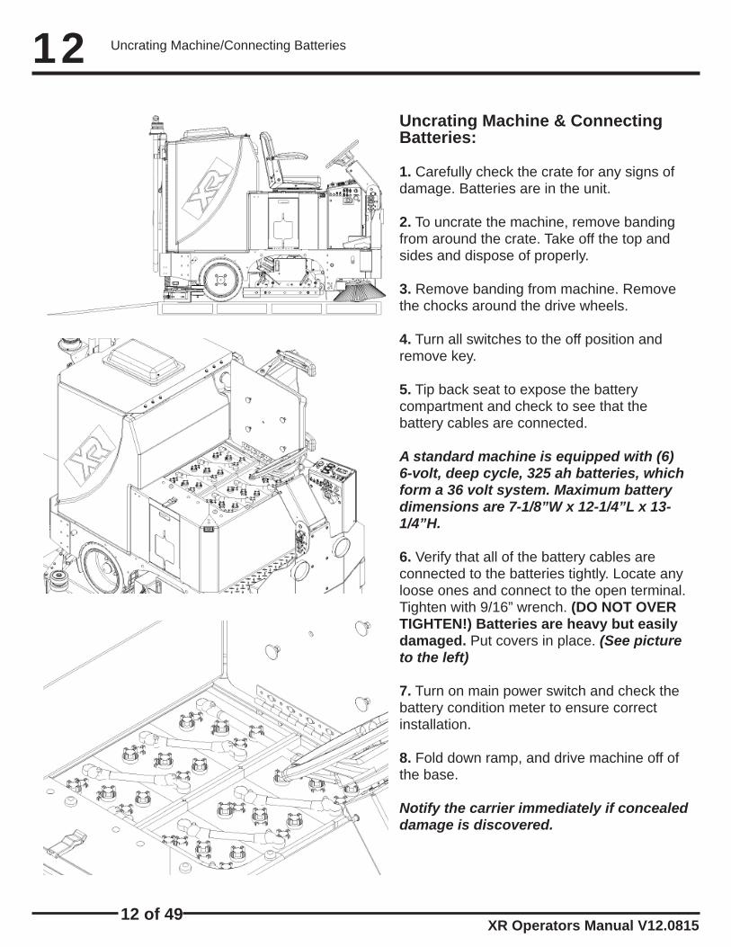
Uncrating Machine & Connecting Batteries:
1. Carefully check the crate for any signs ofdamage. Batteries are in the unit.
2. To uncrate the machine, remove bandingfrom around the crate. Take off the top andsides and dispose of properly.
3. Remove banding from machine. Removethe chocks around the drive wheels.
4. Turn all switches to the off position andremove key.
5. Tip back seat to expose the batterycompartment and check to see that thebattery cables are connected.
A standard machine is equipped with (6) 6-volt, deep cycle, 325 ah batteries, which form a 36 volt system. Maximum battery dimensions are 7-1/8”W x 12-1/4”L x 13-1/4”H.
6. Verify that all of the battery cables areconnected to the batteries tightly. Locate anyloose ones and connect to the open terminal.Tighten with 9/16” wrench. (DO NOT OVERTIGHTEN!) Batteries are heavy but easilydamaged. Put covers in place. (See picture to the left)
7. Turn on main power switch and check thebattery condition meter to ensure correctinstallation.
8. Fold down ramp, and drive machine off ofthe base.
Notify the carrier immediately if concealeddamage is discovered.

13 of 49XR Operators Manual V12.0815
13
A
Attaching Squeegee:
1. Lower the squeegee mounting plate bydepressing the squeegee switch (A) to thedown position. (See picture below)
2. Loosen the four knobs (B) on thesqueegee and slide them into the slots in thesqueegee mounting plate. (See picture below)
3. Tighten the four knobs (B) and connectvacuum hose (C) from the machine to thesqueegee. (See picture below)
4. You may have to adjust the squeegeepitch by turning the pitch adjustment knob (D). (See picture below)
B ECD
5. Note vac exhaust, dual vac out*assists in drying (See picture above)
F
Removing Squeegee:1. With the squeegee in the down position, turnkey switch off & remove key.
2. Disconnect vacuum hose from squeegee and loosen the (4) knobs.
3. Pull squeegee assembly rearward from the lift-ing carrier.
4. Inspect or repair as necessary and reinstall.
Replacing or Rotate Squeegee Blades:For Safety: Before leaving or servicing themachine, stop on a level surface, turn offmachine, and remove key.
1. Remove the squeegee assembly from the machine.
2. Loosen latch (E) and swing both retainingstraps away from squeegee to remove therear squeegee blade. (See picture at lower left)
3. To remove the front squeegee blade,remove all the knobs (F) on the front of thesqueegee assembly, then remove theretaining strap that secures the blade in place. (See picture below)
4. Rotate the squeegee blades to new edgeposition or replace as required.
5. Install blades on the locating pins ofsqueegee assembly.
6. Reinstall squeegee retainer straps.
7. Retighten front knobs & rear latch.
Squeegee Attachment/Removal

XR Operators Manual V12.0815
14
14 of 49
Squeegee Adjustment
1. Turning adjustment knob (A) clock-wise (Tightening) will raise tips & lower center. (See picture to the left)
Adjusting The Squeegee:
2. This squeegee is adjusted too far back and will not pick up on the corners. NOTE: Tips of the blades are off the fl oor. (See picture to the left)
3. This squeegee is adjusted just right with good defl ection across the entire rear blade. (See picture to the left)
4. To adjust the squeegee trail wheels, fi rst loosen locking nut (B). Then turn the wheel as-sembly clock-wise until it bottoms out against the mounting plate and back it off (3) full turns. This is a starting point for adjustment. Raise orlower as needed. Retighten locking nut.
B
A

15 of 49XR Operators Manual V12.0815
15Leveling Scrubdecks
Measure from the deck to the fl oor
C CD
Leveling Disk Decks:1. Drive machine to a fl at level sur-face and turn machine off.
2. Deck should be raised off the fl oor.
3. With the shrouds off, measure from the ground to a parallel surface on all four corners of the scrubdeck. (See picture to the left)
4. If the measurements are not the same the deck is not level and needs to be adjusted.
5. Loosen the (2) locking nuts (C) and adjust the hexagonal arm (D). (See picture to the left)
6. Extending the adjustable arms raises the front and lowers the rear of the scrubdeck. Measure & Retight-en. (See picture to the left)
C D
Measure from the deck to the fl oor
Leveling Cylindrical Decks:
1. Drive machine to a fl at level sur-face and turn machine off.
2. Raise the deck off the fl oor.
3. Measure from the ground to a par-allel edge on all four corners of the scrubdeck.4. If the measurements are not the same the deck is not level and needs to be adjusted.
5. Loosen the locking nut (C) and turn the hexagonal arm (D) on each side of the scrubdeck to level it. (See picture to the left)
6. Extending the adjustable arm raises the front and lowers the rear of the scrubdeck. Measure & Retighten. (See picture to the left)

XR Operators Manual V12.0815
16
16 of 49
Attaching Disk Brushes/Pads
A
B B
C
Attaching Disk Brushes/Pad Drivers:
1. Turn “on” machine power.
2. Raise the scrub deck by depressing thebrush switch (A) to the (“0”) position and turnmachine power “off”. Disconnect batteries.(See picture to the left)
3. Loosen knobs (B) and remove shrouds to ac-cess scrub deck (See picture to the left)
4. Attach pads to pad drivers before connectingpad drivers to motor hub. (See picture to the left)
5. Attach brushes or pads to motor hubs.squeeze the scissor locking device (C) and liftbrush up on to the motor drive hub. Makesure the scissors close and lock once thebrushes are on. (See picture to the left)
6. When brushes are attached put shrouds back on machine and tighten knobs.
**For Correct Pad Application, Call Your Local Dealer**

17 of 49XR Operators Manual V12.0815
17Adjusting Shrouds
Adjusting Shrouds:
1. The shroud must be adjusted correctly in order to have proper water control during turns. The front of the shroud should be slightlyhigher than the rear. (See picture to the left)
2. To adjust shrouds loosen knobs (D) and remove shroud. (See picture to the left)
3. Spin the RED shroud support (E) up or down to get adjustments. (See picture to the left)
4. Once adjusted to the proper height put the shrouds back on top of adjustment supports and tighten knobs back down. (See picture to the left)
D
EE

XR Operators Manual V12.0815
18
18 of 49
Adjusting Cylindrical Side Wipers
Adjusting Cylindrical Side Wipers:
C
A B
1. The cylindrical deck comes equipped with side wipers for increased water control when turning. (See picture to the left)
2. To adjust the side wipers, fi rst loosen the locking nut (A), then turn the adjusting screw (B) in to raise or out to lower the height of the side wiper blade. The spring (C) provides tension during adjustment. (See picture to the left)
3. A properly adjusted side wiper will have slight blade defl ection on the fl oor when turning. (See picture to the left )

19 of 49XR Operators Manual V12.0815
19Tip Back Tank/Solution System
B
A
C
E
D
DON’T LAYUNDER TANK!
Both Tanks Empty!
Strap Tip Back Tank:
1. Fully drain solution tank.
2. Fully drain recovery tank.
3. Tip tank back carefully until supported by tank strap. (See picture to the left)
Solution Filter:
The solution system has an “Inline Filter” (A) to fi lter out cleaning solution prior to scrubbing and a “Gate Valve” (B) to shut off the solution to clean out the fi lter. (See picture to the left)
Cleaning Solution Filter:
1. To clean the “Solution Filter”, unscrew the clear cap (C) from the housing (D) and remove the “Stainless Steel” screen (E). (See picture to the left)
2. Rinse any debris from the screen with clean water.
3. Reinstall screen and screw cap back on tight-ly.

XR Operators Manual V12.0815
20
20 of 49
A
B
C
D
Vac System
Vacuum System:
1. The “high recovery” light (A) (red) willilluminate and the horn will sound when therecovery tank is full. Stop immediately and drainthe recovery tank. (See picture to the left)
2. If the red light is ignored the vac motor willoverheat.
3. If the vac motor is pulling excessive current,circuit breaker (B) (50 amps) may blow toprevent damage. If this occurs contact yourservice agent.
4. Vac switch (C) is set to engage at 45-50” of lift.
5. If foam or water gets past the recoverytank “vac screen/ball system” (D) the“unloader valve” (E) will drain it from the vac box.(See picture to the left and next page top)

21 of 49XR Operators Manual V12.0815
21Vac Filter Box
E 6. “Unloader valve” (E) is located on the bottom ofthe vacuum box in the back of the machine.(See picture to the left)
Vacuum Filter Box: Serial Number 63205 and Newer
FG
7. The “Vac Filter Box” (F) is located in the back of the machine underneath the tank. To access this you need to tip the tank back. This fi lter box captures potential dust and soap and prevents it from getting to the Vac Motors.
8. The Filters (G) inside of the “Vac Filter Box” are placed inside of the box. These disposable white fi lters capture dust and soap from reach-ing the vac motors and need to be replaced when they become restricted or clogged, OR every 6 months.
E
H
9. The “Metal Filter Plate” (H) must be installed with tab facing the “Indexing Pin” (I). The fi lter plate holds the fi lters in place, while the pin holds the cover of the Vac Filter Box on securely to prevent depressurization.
I

XR Operators Manual V12.0815
22
22 of 49
Pre-Cleaning Check List:Read and understand the safety section on pages 6 and 7 before operating this machine.1. Check battery condition gauge on the control panel. Make sure batteries are fully charged be-fore using.2. Check conditions of the pads or brushes.3. Check the condition of the squeegee blades.4. Transport the machine to the fi lling station. Raise the scrub head and squeegee when trans-porting.5. Turn machine off.6. Open solution fi ll lid on the top of the tank and fi ll the tank up (A) with clean water or “approved” detergent. For help call PowerCat Solutions at 414-745-9337. Foam in the recovery tank is usu-ally an indication of excessive soap. NOTE: Wa-ter temperature must not exceed 135°F/57°C and do not use high percentage bleach mix-ture. The clear tube (B) at the rear of the machine indi-cates the amount of water in the tank.7. Add “approved” cleaning chemical. Use the proper dilution ratio indicated on the bottle. Call if unsure.NOTE: Use only non-fl ammable commercial cleaning chemicals. Your authorized distribu-tor can assist you in selecting a proper chemi-cal.
A
B
Operating Hints:1. Observe the amount of solution the machine is dispensing on the fl oor and adjust to the desired fl ow. To increase the solution fl ow rate, push the “+” on the solution switch. To shut the solution off completely, push the “-”.
2. Keep an eye on the clear vacuum cover to make sure there is not any foamy buildup in the recovery tank. If excess foam begins to develop, pour a recommended foam control solution into the recovery tank. Foam is usually an indication of excessive soap.
3. Always operate at lower speeds when scrub-bing around walls and objects. The operator should reduce the speed, to maintain control when turning.
4. If squeegee starts to streak, raise and wipe the blades with a clean cloth. If the problem continues, check the blades for wear or damage, and rotate if needed. You may need to pre-sweep before scrubbing.
5. Change or turn over pads when dirty. Rotate scrub brushes every week from left to right.
6. Stay clear of objects protruding from the fl oor, such as sockets, grates, for they will damage the pads and squeegee blades.
7. During brief stops you do not have to turn any-thing off. The brushes and solution will automati-cally stop when the foot pedalis released.
8. Always keep an eye on your gauges. They let you know the status of a particular system at a glance. If your battery gauge isreading low, you must stop immediately and re-charge. Running the batteries dead will result in damage to the batteries.
9. When you run out of solution, raise the brush-es and continue to vacuum the remaining water until it is consumed. The solution sight hose is used to indicate the level of detergent remaining in the tank.
10. When you are ready to stop, pick up the brushes, turn off the solution switch, lift the squeegee, and drive the machine back to the charging area. Be sure to brain both tanks before storing the machine.
Machine Operation

23 of 49XR Operators Manual V12.0815
23
A
B
C
DE
F G
One Pass Scrubbing:1. Turn machine on with the key switch (A).
2. Lower squeegee by pressing the switch (B).
3. Lower scrub head to the fl oor, use the top half of the brush switch (C).
4. Adjust the solution “+”/”-” to the desired setting (D). (Start at half way)
5. Begin scrubbing by depressing the foot pedal slowly and then to the speed required. (Not Shown)
6. Once the machine begins to move, check the down pressure on the LCD screen (E). To adjust the down pressure, push the toggle switch (F) for-ward to increase the pressure and backwards todecrease the pressure. Start scrubbing at the #1 or #2 marks. Do not use the #4 or #5 marks with-out management’s approval.
7. To operate machine in reverse, simply switch the reverse switch (G) to the reverse position, back up alarm will sound (optional) and your re-verse speed is set to roughly 70% of forward.
8. To stop the machine, let off the foot pedal and the machine will stop automatically. (Not Shown)
Scrub Only:1. Turn machine on with the key switch (A).
2. Lower scrub head to the fl oor, use the top half of the brush switch (C).
3. Adjust the solution “+”/”-” to the desired set-ting (D). (Start at half way)
4. Begin scrubbing by depressing the foot pedal slowly and then to the speed required. (Not Shown)
5. Once the machine begins to move, check the down pressure on the LCD screen (E). To adjust the down pressure, push toggle switch (F) for-ward to increase pressure backward to decrease pressure. Start scrubbing at the #1 or #2 marks. Do not use the #4 or #5 marks without manage-ment’s approval.
6. To operate machine in reverse simple switch the reverse switch (G) to the reverse position, back up alarm will sound (optional) and your reverse speed is set to roughly 70% offorward.
7. To stop the machine, let off the foot pedal and the machine will stop automatically. (Not Shown)
Vacuum Only:1. Turn machine on with the key switch (A).
2. Lower squeegee by pressing the switch (B).
3. Begin vacuuming by depressing the foot pedal slowly and then to the speed required. (Not Shown)
4. To operate machines in reverse, simply switch the reverse switch (G) to the reverse position, back up alarm will sound (optional) and your re-verse speed is set to roughly 70% of forward.
5. To stop the machine, let off of the foot pedal and the machine will stop automatically. (Not Shown)
Machine Operation

XR Operators Manual V12.0815
24
24 of 49
Drain Solution Tank:To drain left over cleaning solution from the solu-tion tank, perform the following steps.
1. Pull the clear sight tube/drain hose (A) off barbed fi tting. (See picture below)
2. Rinse out tank and solution fl ow system with clean water.
Overide Parking Brake:The parking brake must be released prior to at-tempting to “pull/push” the machine manually. Perform the following steps in any order.
1. Disconnect both positive and negative leads (D & E) from the traction motor.
2. Turn wingnut (F) clockwise to release the park-ing brake.
A B
D
E
F
Drain Recovery Tank:Always empty recovery tank when refi lling the so-lution tank. To drain the recovery tank, perform the following steps.
1. Remove drain hose (B) and unscrew cap. Open the top “recovery access lid” and fl ush out with fresh water to keep tank clean.
2. Remove cap and begin draining.NOTE: It is the customers responsibility to verify that discarded water is in compliance with local, state, and federal laws. DO NOT DRAIN INTO “STORM DRAINS” !
3. Open the top “recovery tank lid” and fl ush out with fresh water to keep tank clean. Rinse the recovery tank after every use. This will prevent heavy build up on the bottom of the tank, foul odors and clogging of the drainhose. Empty “Drain Saver” (C).
4. Once tank is empty, put the cap back on and place hose back on hook.
C
Machine Operation

25 of 49XR Operators Manual V12.0815
25Recovery Tank Float Shut Off:When water is no longer being vacuumed from the fl oor and the vacuum fac is operating, the ball fl oat has engaged the red high recovery light (A) will come on.
The vacuum motor will not vacuum water with recovery tank full. The recovery tank must be drained.
1. The fl oat shut off (B) screen can be cleaned in or out of the machine.2. To clean the fl oat shut off while it is inside the machine, wipe material off screen, then rinse. Check that the ball is also clean and moves freely.3. To remove the fl oat shut off, remove the white clamp (C), grasp the screen with one hand, and pull down to remove.
4. Screens, gaskets, and shut off balls must be in place.
A
B
C
Recovery Tank Drain Saver:
The recovery tank drain saver will help prevent the drain from being clogged with debris.
1. The drain saver screen should be emptied and cleaned after you drain the tank.
2. To clean, pull hose (D) out of drain saver and remove screen. Empty screen into trash, wipe material off screen and then rinse.
D
3. When fi nished, place screen back into the re-covery tank and re-insert hose into screen (E)
E
4. The screen saver must always be in place when the machine is in use to prevent clogging of drain.
Recovery Tank

XR Operators Manual V12.0815
26
26 of 49
Charger Specifi cations:
Output voltage of 36 volts. (Standard)Output current of 36 amps max. (Standard)Input voltage of 110 volts/60 Hz. (standard)Automatic shut off circuit.Made for deep cycle batteries.
Danger: Always charge batteries in a well ventilated area. Batteries emit hydrogen gas. Explosion or fi re can result. Keep sparks and fl ame away. Shield eyes when servicing batteries and avoid contact with battery acid.Leave access panel (A) open when charging!
A
Standard Charger:
Caution: The following instructions are in-tended for the 36v charger supplied with the machine. Do not use any non OEM charger with this machine.
1. Transport machine to a well ventilated area for charging.
2. Turn the machine off.
3. Access Panel opens (A) the tank to expose the batteries. (See picture to the left)
Caution: Always wear eye protection when batteries are exposed.
4. Check the water level in each battery. Do notcharge the machine unless the water is slightly higher than the plates. If needed, add enough distilled water to 1/2” above the plates. Do not over fi ll. Batteries can overfl ow during charg-ing. Replace caps before charging.
5. With the grey (175) charger plug discon-nected from the machine, plug the charger power cord into a grounded 110 volt standard wall outlet.
6. Connect the grey charger plug into the battery charging port (B) located on the seat pedestal.
7. The charger will automatically begin charg-ing, and automatically shut off when fully charged. (Check gauge)
8. After the charger has turned off, unplug the grey charger plug from the machine and dis-connect the charger from the wall outlet.
9. Recheck the cell level after charging. If needed, add distilled water up to the correct level. Be certain to replace the caps securely and to wipe off the top of the batteries.
B
Standard Battery Charging

27 of 49XR Operators Manual V12.0815
27Charger Specifi cations:Output voltage of 36 volts. (optional)Output current of 30 amps max. Input voltage of 110 volts/60 Hz.Automatic shut off circuit.Made for deep cycle batteries, wet or sealed.
Danger: Always charge batteries in a well ventilated area. Batteries emit hydrogen gas. Explosion or fi re can result. Keep sparks and fl ame away. Shield eyes when servicing batteries and avoid contact with battery acid.Leave access panel (A) open when charging!
A
Onboard Charger:Caution: The following instructions are intend-ed for the 36v “optional” Onboard Charger (B). (See left middle picture)
1. Transport machine to a well ventilated area for charging.
2. Turn the machine off.
3. Access Panel opens (A) the tank to expose the batteries. (See picture to the left)
4. Check the water level in each battery. Do notcharge the machine unless the water is slightly higher than the plates. If needed, add enough distilled water to 1/2” above the plates. Do not over fi ll. Batteries can overfl ow during charging. Replace caps before charging.
5. Plug the extension cord into a grounded 110 volt/60 Hz standard wall outlet & fl ip switch. (See picture to the left) NOTE: MUST HAVE 20 AMP SERVICE.
6. The charger will automatically begin charging, and automatically shut off when fully charged. (Check gauge)
7. After the charger has turned off, unplug the extension cord from the machine and disconnect from the wall outlet. (See picture to the left)
8. Recheck the cell level after charging. If needed, add distilled water up to the correct level. Be cer-tain to replace the caps securely and to wipe off the top of the batteries.
Description of LED:
Red LED - Battery level low.Yellow LED - Battery at 1/2 charge.Green LED - Battery is fully charged.
B
(Close up of Charger LCD)
Optional Battery Charging

XR Operators Manual V12.0815
28
28 of 49
Power Switch LCD Display
Charge Status LED’s
Onboard Charger Manual

29 of 49XR Operators Manual V12.0815
29Onboard Charger Manual

XR Operators Manual V12.0815
30
30 of 49
Onboard Charger Manual

31 of 49XR Operators Manual V12.0815
31Changing Batteries:
Stop machine in a clean area next to the charger. Turn off machine. For safety: Before leaving or servicing the machine; stop on level surface, turn off machine and remove key. Use eye pro-tection.
1. Tip back tank to expose batteries.
2. Disconnect main battery cables from machine.
3. Use the proper size wrench to disconnect main ground wire fi rst and secure cable terminal away from batteries.
4. Disconnect main positive lead and secure cable and remove one at a time.
5. Loosen both terminals on each jumper cable and remove one at a time, and place away from ma-chine.
6. Prepare a suitable site to place the batteries, store on a wood pallet, not on concrete.
7. Attach suitable battery lifting device and lift batteries from the machine
Warning! Batteries are a possible environmental hazard & extremely heavy. Consult your bat-tery supplier for safe removal & disposal methods. Note orientation of the positive and nega-tive posts is critical for cables to reach. Do not lift from battery posts, which cannot support the weight. (See below)
36 VOLTS!
FRO
NT O
F THE
MA
CH
INE
Changing Batteries

XR Operators Manual V12.0815
32
32 of 49
Side Broom System:1. Flip side broom switch (A) up to lower andengage broom. (See picture below)
A2. To adjust side broom height, loosen lock-ing nut located behind screwhead (B) of screw that is in front of scrubdeck just inside the side wall of frame on each side of the machine. Use 1/2” wrench to loosen locking nut. (See picture below)3. Turn adjustment screw (B) counter-clockwise(loosens) to lower side brooms. Turn screw clock-wise (tightens) to raise side brooms.
4. Side broom pitch adjustment slot (C). (See picture below)
B
C
5. Picture below shows brooms too high.
6. Picture below shows brooms too low.
7. Picture below shows brooms just right.
Side Broom System

33 of 49XR Operators Manual V12.0815
33Overhead Guard: 1. Your machine may be equipped with an”optional” “Overhead Guard” (A) that helps protect the operator from falling objects that are above the operators head. (See picture below)
A
B
C
D
E
Pre Treat Soap:1. Your machine is may be with “optional” “Pre-treat Soap” (B).
2. It helps remove stains that a normal detergent can not get out of fl oor. (See picture below)
HD Side Doors:1. Your machine may be equipped with “optional”“Heavy Duty Side Doors” (C) that helps protect the machine’s scrubdeck from collision damage.(See picture below)
Non Marking Tires:1. Your machine may be equipped with non marking (D) tires, which may have reduced trac-tion on some fl oors. (See picture above)
Industrial Battery:1. Your machine may be equipped with “optional”“Heavy Duty Industrial Battery” and charger thatprovides longer machine run time. (See picture below)
Onboard Charger:1. Your machine may be equipped with “optional” “On-board charger (E) that will charge your ma-chine. (See picture to the left)
Machine Options

XR Operators Manual V12.0815
34
34 of 49
Machine Options:
Spray Hose:(A) Your machine may be equipped with “optional” Spray hose. Permits cleaning in re-mote areas.
Stainless Recovery Tank:(B) Your machine may be equipped with “optional” stain-less steel recovery tank.Diffuser Exhaust:(C) Your machine may be equipped with “optional” diffuser exhaust which helps reduce noise and assist in drying the fl oor by dispersing air evenly to the fl oor.
Vac Wand:(D) Your machine may be equipped with “option-al” Vacuum wand which allows you to vacuum up water in hard to reach places.
Stainless Solution Tank:(E) Your machine may be equipped with “optional” Stainless steel Solution tank.
Industrial Removeable Batteries:(F) The Industrial Battery we sell is one whole unit that requires and specifi c lift out too for a forklift. This allows to have a fully charged back-up ready for a quick switch with a fork lift.
Roll Out Battery Box:(G) The Roll Out Battery Box has the same func-tionality as the Industrial Removeable Battery Unit, but with the ability to do so without a forklift. This provides for easy switching between full sets of batteries.
A
B
C
D
E
FG
Machine Options

35 of 49XR Operators Manual V12.0815
35Machine Options:
Heavy Duty Soap
Normal Soap
No Soap
Onboard Soap:1. Switch toggle switch up once fornormal soap distribution and up twice for heavy duty soap distribu-tion. (A)
Spray Hose:1. Turn on spray jet pump using the toggle switch on the centralcommand. (B)2. Detach spray hose from back of machine and squeeze handle.
Vac Wand:1. Detach vac hose from squeegee and attach it to the vac wand. (See picture above)2. Turn on vac motors us-ing the toggle switch on the central command. (C)
A
B
C
Attach Vac Hose Here
Machine Options

XR Operators Manual V12.0815
36
36 of 49
Daily Maintenance:1. Remove and clean pads or brushes. Never use soiled pads when cleaning. Replace pads when they become packed with residue.2. Remove and clean debris from the fl oat shut-off screen and drain saver located inside the recovery tank.3. Drain and rinse tanks thoroughly.4. Inspect vacuum hose for any objects obstruct-ing the air fl ow.5. Raise squeegee and wiper blades with a clean cloth. Store squeegee in the raised position to prevent damage or setting of the blades.6. Wipe down machine if needed. Use a non-abrasive, non solvent cleaner, or a clean damp cloth.7. Recharge the batteries if needed.
Weekly Maintenance:1. Check battery water level in each cell of the batteries, and fi ll as needed. Always usedis-tilled water to refi ll batteries. Batteries should be fi lled approximately 3/4” to 1” above the plates. Overfi lling will cause the batteries to leak during charging. The charging process creates gasbubbles inside the battery, which effectively in-creases the volume of the electrolyte.
2. Clean battery tops to prevent corrosion.3. Rotate brushes. Rotate the left to the right and right to left. On cylindrical models from front to back, or end to end if using different materials.4. Drain and rinse tanks thoroughly. To thorough-ly fl ush out any solution chemicals in solution line and valves, refi ll solution tank with a few gallons of warm clean water and run machine until tank is empty.
Monthly Maintenance:1. Check scrub head and squeegee lifting cables for wear and spring tension.
2. Check machine for water leaks and loose nuts and bolts.3. Check to see if battery cables are tightened(Tighten if needed)4. Check parking brake.
Yearly Maintenance:Call your local dealer for yearly maintenance.
Storing Machine:1. Be sure to fl ush the tanks out completely. To thoroughly fl ush out any solution chemicals in solu-tion line and valves, refi ll solution tank with a few gallons of warm clean water and run machine until tank is empty.2. Open the recovery tank lid to promote air circu-lation.3. Raise brushes and squeegee.
Checking Battery Specifi c Gravity:Use a hydrometer to check the battery specifi c gravity.
Checking Gravity:A. HydrometerB. BatteryNOTE: Do not take readings immediately after adding distilled water, if water and acid are not thoroughly mixed, the reading may not be ac-curate.Check the hydrometer against this chart:
Specifi c Gravity @ 80°F/27°C
Battery Condition
1.265 100% Charged1.225 75% Charged1.190 50% Charged1.155 25% Charged1.120 DISCHARGED
NOTE: If the readings are taken when the bat-tery electrolyte is any temperature other than 80vF (27vC), the reading must be temperature corrected.To fi nd the corrected specifi c gravity readingwhen the temperature of the battery electrolyteis other than 80vF (27vC): add (+) to the spe-cifi c gravity reading 0.004 (4 points), for each 10vF (6vC) above 80v (27vC) subtract (-) from the specifi c reading 0.004 (4 points), for each 10vF (6vC) below 80vF (27vC).
Maintenance
37 of 49XR Operators Manual V12.0815
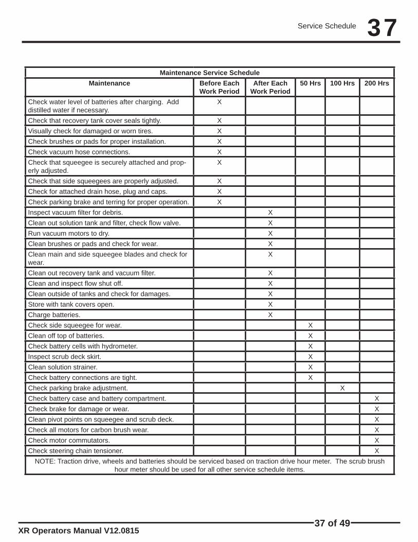
37Maintenance Service Schedule
Maintenance Before Each Work Period
After Each Work Period
50 Hrs 100 Hrs 200 Hrs
Check water level of batteries after charging. Add distilled water if necessary.
X
Check that recovery tank cover seals tightly. XVisually check for damaged or worn tires. XCheck brushes or pads for proper installation. XCheck vacuum hose connections. XCheck that squeegee is securely attached and prop-erly adjusted.
X
Check that side squeegees are properly adjusted. XCheck for attached drain hose, plug and caps. XCheck parking brake and terring for proper operation. XInspect vacuum fi lter for debris. XClean out solution tank and fi lter, check fl ow valve. XRun vacuum motors to dry. XClean brushes or pads and check for wear. XClean main and side squeegee blades and check for wear.
X
Clean out recovery tank and vacuum fi lter. XClean and inspect fl ow shut off. XClean outside of tanks and check for damages. XStore with tank covers open. XCharge batteries. XCheck side squeegee for wear. XClean off top of batteries. XCheck battery cells with hydrometer. XInspect scrub deck skirt. XClean solution strainer. XCheck battery connections are tight. XCheck parking brake adjustment. XCheck battery case and battery compartment. XCheck brake for damage or wear. XClean pivot points on squeegee and scrub deck. XCheck all motors for carbon brush wear. XCheck motor commutators. XCheck steering chain tensioner. X
NOTE: Traction drive, wheels and batteries should be serviced based on traction drive hour meter. The scrub brush hour meter should be used for all other service schedule items.
Service Schedule

XR Operators Manual V12.0815
38
38 of 49
Preventive Maintenance

39 of 49XR Operators Manual V12.0815
39Preventive Maintenance

XR Operators Manual V12.0815
40
40 of 49
Troubleshooting Central Command:Note: This machine is operated by a sophisticated electronic “controller” that has many fail-safes within it. It self-analyzes problems and fl ashes a four-digit alpha-numeric code of what is wrong in the LCD window. Most of these codes require a technician attention. You should not attempt repairs you are unfamiliar with, especially if you are not authorized to work on this equipment.The complete list of codes is published in the simplifi ed electronic troubleshooting manual, which is available to authorized and certifi ed distribution technicians. However, we have in-cluded the basic codes that you can usually resolve yourself.
1. 7601 and 7602 ERROR: Scrub deck current over load.This can occur when driving over a bump in the fl oor. Torestart, turn off the key and turn it on again. To avoid thiserror, either slow down on bumpy parts of the fl oor, orreduce down pressure on the pads.
2. 1500 ERROR: There is an open in the parking brakecircuit. Check the parking brake wiring and the parkingbrake coil to fi nd the open circuit.
3. 770, 7701, 7702, and 7703 ERROR: The vacuum motor has exceeded their authorized power limits. Turn off key and turn on again to clear.
4. BOOST ON: Allows front wheel drive to draw morepower when needed to climb ramps for 30 seconds.
Troubleshooting - Central Command

41 of 49XR Operators Manual V12.0815
41Troubleshooting Central Command:
5. 7700: Vacuum motor circuit is open.
6. Throttle ERROR: You pressed the foot pedal beforeturning on the key. Turn off the key and try again, leavingfoot off of the pedal.
7. 2C00 and 2C01 ERROR: Low voltage warning. Voltagehas dropped down below the minimum required tooperate the machine. If you wait a few minutes, thebatteries may come up in voltage, allowing you to drivevery slowly to the recharge station. If not, you will have torelease the parking brake (on the front wheel, pull levertoward the front of the machine to release) and push themachine to recharging station. You must disconnect thetraction motor! (+ cable fi rst)
8. 7802 ERROR: The traction motor pulled excessive cur-rent perhaps running a ramp for more than the 60 secondsallowing for this. Turn off the key, turn on again, andcontinue. You should not use this machine to climb rampsso steep and so long that this code comes up repeatedly,or you could overheat the traction motor.
9. All other ERROR codes: Turn off the key, and disconnect the positive battery cable from the bat-teries for more than one minute (the time is needed to drain the controler on-board capacitor). Recon-nect cables, being sure that it is tight. Too loose and you will burn battery. If you over tighten the cables you can damage the battery lead terminal. Try again.
10. If the problems cannot be solved by any of this solution, call your local dealer service de-partment.
Troubleshooting - Central Command

XR Operators Manual V12.0815
42
42 of 49
CENTRAL COMMAND IISYSTEM DIAGNOSTIC CODES
Code Fault Description Course of correction0204 Controller Memory Corrupt Disconnect battery for 2 minutes. Reconnect. If code is still present replace the control.0700 Bias Voltage Error High reference signal is grounded0701 Mid Rail Voltage High0702 Mid rail bias voltage high0704 12V supply failure0705 2.5 V reference error0706 High reference ground fault 5 Volt reference is Contacting 0 Volt Reference0810 Throttle High reference error For all Throttle Diagnostic Codes0811 Throttle Max Wiper Difference Error Check throttle wiring for shorts or opens. Repair or replace as necessary.0812 Throttle Max Pull Down Difference Error If diagnostic code is not cleared, then replace the throttle potentiometer0813 Throttle Max Pull Safe Difference Error0814 Throttle Reference Error0815 Throttle Lo Reference Error0816 Throttle Hi Reference ISO Error0817 Throttle Lo Reference ISO Error0818 Throttle Error: Both have Readings0A01 Power down error Check the wiring to the main power switch. This code indicates rapid power cycling1310 Excessive Current Trip Current Draw on Control exceeds maximum limit of 250 amps
Resistance in the machine's Main Breaker and/or battery cable to controlGives a false reading to the control.
1311 Brush head actuator, excessive current Device connected to the brush head actuator has exceeded maximumlimit of 21 amps surge value and 7 amps continuous.Check that the arms are not too tight (torque = 25 inch lbs, almost fingerloose). Check that actuator system is not binding.
1312 Squeegee actuator, excessive current Device connected to squeegee actuator (on riders) has exceeded maxlimit of 21 amps surge value and 7 amps continuous load.Check that the arms are not too tight (torque = 25 inch lbs, almost fingerloose). Check that actuator system is not binding.
1313 Solution valve circuit output( Aux 3 ), excessive current Current exceeded seven amps max. Check valve operation. Coil maybe corroded, or short in wires.
1314 Soft Aux 4 Over current Occurred Aux 4 is one of the following: High Vac Horn, Under Seat Fan, Suds Valve1318 Soft Brake light Over current Occurred Brake light circuit not used by us at this time.131C Backup Alarm Over current occurred Backup alarm drew more than 2 amps max allowed. Check inline resistor
on some models. If resistor is bad, remove it, and put piece of duct tapeover speaker of alarm. (Reverse EMF from the echo is causing the problem)
1321 Aux 1 (Brush Actuator) Over current 2 Occurred Brush actuator exceeded 12 amps for less than 0.1 sec.See notes for 1311
1322 Aux 2 (Squeegee Actuator) Over current 2 Occurred Squeegee actuator exceeded 12 amps for less than 0.1 sec.See notes for 1312
1331 Relay #1 failure. Traction Drive relay Relay current limit exceeded or contacts are may be damaged.1332 Relay #2 failure. Output (brush, vac all others) relay. Relay current limit exceeded or contacts are may be damaged.1400 Bridge Fault 1 - Brush or traction motor not in correct
voltage range. Possible short between B+ and the high amperage outputs1401 Bridge Fault 2 - Voltage difference on traction bridge
too great1402 Brush Bridge Fault - Battery/Brush bridge voltage
difference too great1411 Brush actuator positive wire is shorting Find appropriate wire and remove short.1412 Brush actuator negative wire is shorting Find appropriate wire and remove short.1413 Squeegee actuator positive wire is shorting Find appropriate wire and remove short.1414 Squeegee actuator negative wire is shorting Find appropriate wire and remove short.1500 Brake Fault - Solenoid brake circuit is open Parking Brake is disconnected or coil of brake is open.1501 Brake Fault - Solenoid brake circuit is shorted Parking Brake coil or wiring is shorted.1502 Brake Fault - Brake Over Current Error Parking brake coil is shorted internally or wiring too it is shorted1503 Solenoid brake driver fault1504 Solenoid brake interlock fault1507 Brake Over current Parking Brake is drawing too much power. Check wiring and brake.1600 High Battery Error Battery voltage is too high. Batteries hooked up wrong, or still on charger.1704 Internal Power up error Disconnect battery for 2 minutes. Reconnect. If code is still present replace the control.1705 Short to B+ on Traction or Brake output Either the traction or brake output is shorted to B+1706 Short to B+ on Brush, Vac or Aux outputs Either the Brush, Vacuum or an Aux output is shorted to B+1800 Controller Internal Timer Failure Disconnect battery for 2 minutes. Reconnect. If code is still present replace the control.1D02 Spec Change Trip This is normal--comes up when you reprogram the control. Turn key off and
on to reset the program.1E03 Inhibit activated Interlock switch closed or wiring to it is damaged. Charger interlock switch.1E04 Inhibit Activated 2 Interlock switch closed or wiring to it is damaged. 1E06 Inhibit Input Out of Range Interlock switch closed or wiring to it is damaged. 2C00 Low Battery Error Voltage in battery dropped too low (18 volts on 24V system; 28V on 36V system)2C01 Low Battery Error--2 Recharge the battery in either case. check voltage under load to see if a bad2C02 Battery lockout occurred cell is pulling down voltage.2C03 Battery Lockout occurred--2
FORM 10003 1 OF 2 REVISED: 9/9/2009
Troubleshooting - ERROR Codes

43 of 49XR Operators Manual V12.0815
43CENTRAL COMMAND II
SYSTEM DIAGNOSTIC CODESCode Fault Description Course of correction2F01 Throttle Displaced Error Throttle was activated when key was turned on. Release throttle. Restart machine.3A00 Bad Program Settings You reprogrammed the control with settings that are not authorized.3100 Low bridge voltage Probable short circuit of output device or wiring3101 Traction bridge fault3102 Brush/Vac bridge fault3103 Waiting for bridge to charge3603 Micro Processor Error Check to make sure there are no outputs shorted to battery. Disconnect the battery
for 2 minutes and reconnect. If the code is still present replace controller.7000 Startup With Push Selected Freewheel input signal selected at startup. Disconnect freewheel switch.7001 Push Activated in Drive Mode Freewheel input signal activated while driving. Disconnect freewheel switch.
NOTE: As of this writing, we do not use Freewheel. This permits pushingmachine more easily by disconnecting traction motor from control.
7500 Throttle Comms Time Out Problem with LCD dash module or with wiring to it. Check and replace as necessary.7501 LCD Module settings corrupt Disconnect batteries and wait 2 minutes to reconnect. If code does not clear replace LCD.7600 Brush motor not connected Check for open circuit to brush motors.7601 Soft Brush Current Fold back Too much load on brush motor. May be from hitting a bump or wire tangled in
brush drive mechanism. Possible wiring or brush motor short.7602 Soft Brush Current Fold back--2 Same as above.7603 Soft Brush Current Fold back--3 Same as above.7604 Brush Inhibit is on We do not use Brush Inhibit at this time.7605 Brush startup over current detection You may have started brushes on carpet or rubber or other high resistance material.
This may have stalled motor before actuator could react to lift brush head up.If chronic problem, call Factory to discuss reprogramming machine for application.
7700 Soft Vacuum Motor Disconnected Error Check wiring to vac motor. On 390, check wiring to Hella relay for vac motor7701 Vac Motor Current Fold back Too much amp load on vac circuit. Check wiring. May come from picking up
large column of water.7702 Soft Vacuum Current Fold back--2 Same as above7703 Soft Vacuum Current Fold back--3 Same as above7800 Traction Motor Circuit Open Check traction motor wiring and connectors. Include connector at steering pivot under
floor cover!7801 Traction Motor Over current Error Too much current due to bad motor or wiring to motor.7802 Soft Traction Motor in Fold back State Traction motor being overloaded, or ramp climbing that took longer than 60 seconds.
(Fold back means normal low amp setting to motor. There is one minute ramp climbingsurge that may be 4 times as high as the fold back rate).
7803 Motor Line Voltages Instability Timeout May be loose wire at motor or at control. Possible motor problem7804 Traction Drive in BOOST mode The traction Drive is in the boost mode. This is normal on heavy acceleration or on ramps.7880 Traction Speed Input Out of Range Throttle setting wrong for motor speed. Check throttle pot. and wiring.7900 Emergency Stop Error Emergency Stop Button is Actuated when you tried to move. Optional button.7901 Soft Belly Button Actuated Belly Button Switch activated. We don't use this.8000 Service Mode Service Timer Limits have been reached. We don't normally use them; they are
dealer option.9000 Brushes not fitted Check brush deck to make sure brushes are on, and on securely.0003 Possible terminal short in system For all of these Diagnostic Codes:0100 1. Turn off key switch and disconnect battery for two minutes, using your watch to 0B02 measure time.1802 2. When you reconnect battery, you must see a spark. This shows the control's 1B20 on-board capacitor has been discharged and has been refilled.1B21 3. Restore the battery connection. Make sure battery cable is on tight before trying2102 machine or you could burn battery posts and cable. 2103 4. Turn on machine. If diagnostic code still shows, then replace the control.2D013104310532003201321032113212321332143601360236083609360a360b360d360e
FORM 10003 2 OF 2 REVISED: 9/9/2009
Troubleshooting - ERROR Codes

XR Operators Manual V12.0815
44
44 of 49
Troubleshooting Machine Operations:
Problem: Cause: Solution:
No power, nothing operates Faulty key switchBatteries need chargingFaulty batteryLoose battery cableMain circuit breaker tripped
Contact local servicing dealerSee charging batteriesReplace batteryTighten loose cableWait 5 minutes for auto resetDetermine cause and correct
Brush motor(s) do not operate Brush deck is not downFoot pedal is not depressedBrush circuit breaker tripped
Carbon brushes wornFaulty brush motor or wires
Put brush deck downEngage foot pedalWait 5 minutes for auto resetDetermine cause and correctContact local servicing dealerContact local servicing dealer
Drive motor does not operate Recharge switch misadjustedFaulty speed controller or wiresFaulty drive motorFaulty wiringCarbon brushes worn
Contact local servicing dealerContact local servicing dealerContact local servicing dealerContact local servicing dealerContact local servicing dealer
Vacuum motor does not operate Squeegee is in the up positionFaulty vacuum switchVacuum circuit breaker tripped
Faulty vacuum motor
Rotate squeegee lift level downTry operating “white” toggleWait 5 minutes for auto resetDetermine cause and correctContact local servicing dealer
Drive motor runs incorrectly Faulty speed controller or wiresFaulty potentiometerLoose wires
Contact local servicing dealerContact local servicing dealerContact local servicing dealer
Insuffi cient solution fl ow Solution tank low
Flow knob turned downSolution fi lter cloggedSolution line clogged
Solution valve clogged
Refi ll solution tank, drain recov-ery tankMove lever to “On”Remove cover and cleanRemove and blow out with com-pressed airRemove cover and clean
Troubleshooting - Machine

45 of 49XR Operators Manual V12.0815
45
Problem: Cause: Solution:
No solution fl ow No solution in tankSolution valve offSolution switch offSolution screen cloggedFaulty solution solenoidFaulty solution switch
Fill solution tankRotate lever to onTurn solution switch onRemove and clean screenContact local servicing dealerContact local servicing dealer
Poor water recovery Recovery tank is fullBall/screen in recoveryTank is cloggedVacuum hose is cloggedSqueegee is cloggedSqueegee blade is wornFaulty vacuum hoseVacuum motor gasket tornTank gasket faultyDrain plug looseVac motor faultyBattery charge low
Empty recovery tankRemove screen and clean
Remove debrisRemove debrisRotate or replace bladesContact local servicing dealerContact local servicing dealerContact local servicing dealerTighten lidContact local servicing dealerCharge batteries overnight
Poor water recovery on turns Wipers wornWipers chatterSqueegee swing is bindingIncorrect squeegee size
Replace wiper materialTighten pivot pointsContact local servicing dealerContact local servicing dealer
Rear tires noisy Bearing dryFaulty hubs
Grease bearingsContact local servicing dealer
Poor traction Excessive brush pressureWorn drive tireHeavy soap concentration
Reduce pressure with switch
Contact local servicing dealer
Short run time Batteries run downBatteries still downBatteries low on water
Batteries over cycled
Charge batteries twiceContact local servicing dealerFill with distilled water to 3/4”above the lead platesContact local servicing dealer
Troubleshooting Machine Operations:
Troubleshooting - Machine

XR Operators Manual V12.0815
46
46 of 49
Battery Maintenance Guide
47 of 49XR Operators Manual V12.0815
47
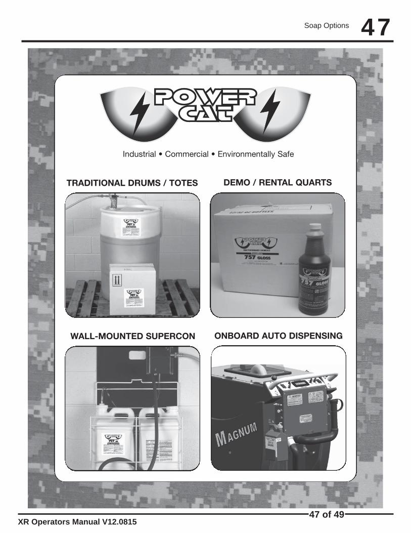
TRADITIONAL DRUMS / TOTES
WALL-MOUNTED SUPERCON
DEMO / RENTAL QUARTS
ONBOARD AUTO DISPENSING
Industrial • Commercial • Environmentally Safe
Soap Options

XR Operators Manual V12.0815
48
48 of 49
PowerCatP.O. Box 503Racine, WI 53404-0503Phone: 414-745-9337Fax: 262-632-1630www.powercatsolutions.com
Distributed by:
PowerCat, LLC, 2008.
An environmentally cleaner that works! It is a solvent freedegreaser that works on oil, carbon, even rubber marks.Incorporates the latest technology in “Green Cleaning”.
Safe on most surfaces not harmed by water alone. Low scale formula to prevent alkali buildup in cleaning equipment, while offer detergent to emulsify oil.
Ideal solvent fortified degreaser. This butyl based detergent is penetrating, fast acting, and deep cleaningwith built-in corrosion inhibitors. It is our most effectivedegreaser.
A high gloss detergent designed to dry to a bright shine.It is ideal for use on finished surfaces, tile, epoxy, orenamel. The special formula removes salt residue, scuffmarks and dirt, while leaving no residue behind. The resultis a clean, non-slip surface, ready for immediate use.
The Heavy Duty concentrate is a Super alkaline detergent, formulated for heavy soil, grease, and thickbuildup. Popular in machine shops, auto and truck repair, and other facilities with oil, hydraulic fluids and cutting oils.
Designed to quickly remove tire marks, oil stains andbuildup that has accumulated. This pretreat uses thepowerful cleaning of natural citrus extract and is intendedto be used directly on the floor at 100% concentrate.
Ideal for applications with Hard Water problems. It is safeto use in pressure washers and automatic scrubbers. Theformulation enhances soil suspension, digests oil andgrease, while supporting extra water conditioner.
**Below Sold in bulk concentrate only. Not available as a SuperCon, PowerDose or SUDS product.
SUDS
Approved
707 Citrus Green
733 Low pH
755 High Power
757 Gloss
797 HD
FORMULASOnboard Availability
727 Pretreat**
744 Tough Stuff**
SUDS
Approved
SUDS
Approved
SUDS
Approved
SUDS
Approved
Soap Options
