version 2, 2017 - · pdf filethe sizing and placement of rock is not an exact science. in...
TRANSCRIPT

Version 2, 2017

© Catchments & Creeks Pty Ltd V2 – July 2017 Page 2
Use of Rock in Waterway Engineering
Version 2, July 2017 Prepared by: Grant Witheridge, Catchments and Creeks Pty Ltd
Published by: Catchments and Creeks Pty Ltd
Diagrams by: Grant Witheridge, Catchments and Creeks Pty Ltd
Photos by: Catchments and Creeks Pty Ltd, and Ross Coventry Except as permitted under copyright laws, no part of this publication may be reproduced within another publication without the prior written permission of the publisher.
Permission, however, is granted for users to: · store the complete document on a database, but not isolated parts of the document · print all or part of the document, and distribute such printed material to a third party · distribute the complete document in electronic form to a third party, but not isolated parts of
the document. All diagrams are supplied courtesy of Catchments and Creeks Pty. Ltd. and remain the ownership of Catchments & Creeks Pty. Ltd. No diagram or photograph maybe reproduced within another publication without the prior written permission of the Director of Catchments and Creeks Pty. Ltd.
This document should be referenced as:
Witheridge 2017, Use of rock in waterway engineering. Catchments and Creeks Pty Ltd., Brisbane, Queensland
Key words: rock stabilisation, rock placement, rock pads, rock beaching, bank stabilisation, rock-lined channels
Copies of this document may be downloaded from: www.catchmentsandcreeks.com.au
© Catchments & Creeks Pty Ltd, 2017 Disclaimer Significant effort has been taken to ensure that this document is representative of current best practice with regards to the sizing and placement of rock within stormwater and waterway engineering. However, the author cannot and does not claim that the document is without error, or that the recommendations presented within this document will not be subject to future amendment.
The sizing and placement of rock is not an exact science. In general, the use of rock in waterway engineering produces more ‘natural’ outcomes; however, these outcomes are also likely to be more susceptible to hydraulic failure.
As such, no warranty or guarantee, express, implied, or statutory is made as to the accuracy, reliability, suitability, or results of the methods or recommendations.
The author shall have no liability or responsibility to the user or any other person or entity with respect to any liability, loss, or damage caused, or alleged to be caused, directly or indirectly, by the adoption and use of any part of the document, including, but not limited to, any interruption of service, loss of business or anticipatory profits, or consequential damages resulting from the use of the document.
Specifically, adoption of the recommendations and procedures presented within this field guide will not guarantee:
· compliance with any statutory obligations · avoidance of environmental harm or nuisance · the design of engineering structures that will be stable in all flow conditions.

© Catchments & Creeks Pty Ltd V2 – July 2017 Page 3
Contents Page Purpose of field guide 4 About the author 4 Introduction 4
Use of rock in waterway channels 6 Background to the rock sizing equations 7 Critical design issues 8 Alignment of the weir crest 10 Use of filter layers and filter cloth 12 Identification of dispersive and slaking soils 13 The placement of rock over dispersive soils 14 Manning’s roughness of rock-lined surfaces 15 Maximum bank gradient 16 Typical properties of rock 17 Thickness and height of rock layer 17
1. Bank Stabilisation Introduction 19 Attributes of rock stabilised waterway banks 20 Critical design issues 22 Sizing of rock placement within low-gradient waterways 24 Toe stabilisation of waterway banks 25 Rock placement on banks 26 Vegetated bank stabilisation works 28 Stacked boulder walls 29 Common problems associated with rock stabilisation of waterways 30
2. Culvert Bed Roughness Introduction 33 Rock placement 34 Hydraulic properties of pipe culverts containing artificial bed roughness 35 Hydraulic properties of box culverts containing artificial bed roughness 35
3. Culvert Outlet Structures Introduction 39 Hydraulics of culvert outlets 40 Sizing rock downstream of culvert outlets 41 Selecting the appropriate length of rock protection 42 Common construction problems 45
4. Waterway and Gully Chutes Introduction 47 Key design considerations 48 Design features 49 Sizing rock for the face of waterway and gully chutes 50 Thickness and height of rock layer 51 Rock type and grading 52 Backing material or filter layer 52 Placement of vegetation over the rock cover 52 Grouted boulder waterway structures 56 Common construction problems 57
5. Waterway Riffles Introduction 59 Rock riffles, chutes, ramps and weirs 60 Sizing rock for low-flow conditions 61 Sizing rock for high-flow conditions 62 Specification of rock for constructed riffles 62
References 63

© Catchments & Creeks Pty Ltd V2 – July 2017 Page 4
Purpose of field guide This field guide has been prepared specifically to:
· provide a general overview of engineering practices associated with the sizing and placement of rock within waterways and constructed channels
· assist engineers in understanding how the sizing of rock for may vary from structure type to structure type
· assist engineers in understanding the most common failure modes of rock-lined engineering structures.
The photos presented within this document are intended to represent the current topic being discussed. These photos are presented for the purpose of depicting either a preferred or discouraged outcome (as the case may be). In some cases the photos may not represent current best practice, but are simply the best photos available to the author at the time of publication.
The caption and/or associated discussion should not imply that the actual site shown within the photograph represents either good or bad stormwater practice. The actual circumstances, site conditions and history of each site are not known in each case, and may not be directly relevant to the current discussion. This means that there may be a valid, site-specific reason why the designer chose the design or layout depicted in the photo.
About the author Grant Witheridge is a civil engineer with both Bachelor and Masters degrees from the University of NSW (UNSW). He has over 30 years experience in the fields of hydraulics, stormwater management, creek engineering and erosion & sediment control, during which time he has worked for a variety of federal, state and local governments, and private organisations.
Grant commenced his career at the UNSW Water Research Laboratory constructing and operating physical flood models of river floodplains. He later worked for Brisbane City Council on creek engineering and stormwater management issues. He currently works through his own company Catchments & Creeks Pty Ltd.
Grant is the principal author of the revised Queensland Urban Drainage Manual (2007 & 2013), Brisbane City Council’s Natural Channel Design and Creek Erosion guidelines; the IECA (2008) Best Practice Erosion & Sediment Control documents, and the 2002 engineering guidelines on the Fish Passage Requirements for Waterway Crossings.
Introduction Rock is a natural substance, however, this does not mean that the placement of rock within waterways will always be deemed ‘natural’. At best, engineers should aim to ensure the use of rock within waterways is done in a manner that demonstrates natural aesthetics and attributes, but with a degree of structural stability that is considered acceptable.
When used in an appropriate manner, rock can greatly enhance the ‘natural’ beauty of an engineered structure; however, the price engineers pay for such natural attributes is the enhanced risk of structural failure. Rock-lined stormwater and waterway structures are highly susceptible to structural failure, especially during the first few years following their installation.
In general, rock-lined structures age well. The filling of all voids with soil and the establishment of plants over the rocks generally helps to increase the structural stability of these systems.
Care and attention in rock placement can result in very good outcomes, while poor attention to what may appear to be just a minor design detail can ultimately lead to total structural failure.
Successful outcomes largely depend on: · the experience of those engineers applying the various rock-sizing equations · the experience of those placing (constructing) the rock-lined structure · the weather and flows conditions experienced during the vegetation establishment phase.
Possibly more than most other areas of waterway engineering, the appropriate use of rock depends on the local site conditions.

© Catchments & Creeks Pty Ltd V2 – July 2017 Page 5
Introduction
Fact Sheet: Rock sizing equations · A report on the development of the rock
sizing equations found within this document can be found on the ‘Catchments and Creeks’ web site.
· http://www.catchmentsandcreeks.com.au/fact-sheets/esc_rock_sizing.html
Background to rock sizing equations
Fact Sheet: Rock roughness equation · A report on the development of the rock
roughness equations found within this document can be found on the ‘Catchments and Creeks’ web site.
· This reference document details the development of a new equation applicable to the shallow water conditions typically found in waterways during periods of low flow.
· http://www.catchmentsandcreeks.com.au/fact-sheets/esc_rock_sizing.html
Background to rock roughness equation
Design and Construction of Urban Stormwater Management Systems · ASCE (1992) Manuals and Reports of
Engineering Practice No. 77, and Water Environment Federation Manual of Practice FD-20, American Society of Civil Engineers, New York
ASCE (1992)
Riprap Design and Construction Guide · Public Safety Section, Water management
branch, Province of British Columbia, Ministry of Environment, Lands and Parks
Riprap Design and Construction Guide

© Catchments & Creeks Pty Ltd V2 – July 2017 Page 6
Use of rock in waterway channels
Channel bank stabilisation · Rock stabilisation has been one of the
most widely adopted techniques for the control of waterway bank erosion.
· Historically this technique consisted of loosely placed rock with open voids.
· However, modern practice has seen a greater use of fully planted rock placement where all voids are filled with soil and pocket planted.
Rock-lined bank stabilisation
Culvert outlets and bed roughness · Similar hydraulic forces exist at the outlets
of multi-cell culverts and multi-pipe drainage systems, consequently the rock sizing charts use in culvert design are similar to those for multi-pipe outlets.
· To enhance fish passage conditions through culverts it becoming common for rock to be placed, either loose or grouted, to the culvert bed to mimic natural bed conditions within the nominated ‘wet’ cells.
Culvert outlet scour control
Waterway and gully chutes · A ‘waterway chute’ is a stabilised section
of a waterway bed used to control bed erosion while maintaining desirable fish passage conditions in a manner similar to a natural riffle.
· A ‘gully chute’ is a steep drainage chute, typically of uniform cross-section, used to stabilise head-cut erosion and/or flow into, or out of, a drainage gully.
· In effect, gully chutes are just larger versions of a drainage batter chute.
Waterway chute
Waterway riffles · A riffle is an isolated section of channel
bed where the steepness of the bed allows for a local acceleration of flows and the possible exposure of the bed rocks during periods of low flow.
· In pure hydraulic terms, riffles are the same as rock chutes and rock ramps; however, their small size and low gradient means the design procedures used for sizing the rock are different from those used in the design of some drainage chutes such as batter chutes.
Waterway riffle

© Catchments & Creeks Pty Ltd V2 – July 2017 Page 7
Background to the rock sizing equations
Use of ‘average’, ‘depth-average’ and ‘local’ flow velocity in sizing rock · Rock displacement occurs as a result of
local forces, local shear stresses, and local velocities.
· Logic would therefore suggest that rock size is best determined through use of the ‘local’ flow velocity or shear stress.
· However, the practicalities of fluid dynamics means that it is the average flow conditions measured over a vertical plain above the rock (i.e. the ‘depth-average’ value) that must be used.
Depth-average flow velocity above rocks
Use of unit flow rate (q) as the preferred equation variable · Using flow velocity or the depth-average
velocity in the determination of rock size introduces unnecessary ‘errors’ into the design procedure due to the problems of determining the Manning’s roughness of the rock-lined surface.
· Units of ‘q’ are m3/s/m
q = (1/n) . Y 5/3 . S 1/2
· where Y = water depth at given location, and S = hydraulic gradient of flow.
Unit flow rate within an irregular channel
Problems associated with the use of shear stress and the Shields Equation in determining rock size · Traditionally, rock sizing equations have
used shear stress as the primary variable, which resulted in the development of the Shields Equation.
· However, the Shields Equation does not take into account the additional restraining forces associated with the weight of the upper rocks sitting on the lower rocks, which is a critical factor when rocks are placed on steep slopes.
Rocks placed on a steep slope
The effects of air entrainment and whitewater flow conditions · Air entrainment into the water causes a
reduction in the density of the water passing over the rocks.
· As a result, the effective flow depth increases and the forces exerted on the rocks by the water decrease.
· In addition, rock stability can increase due to the reduced effects of buoyancy on the submerged rocks (lower water density).
· Thus the adopted rock-sizing equations can over-estimate the required rock size. Whitewater flow conditions

© Catchments & Creeks Pty Ltd V2 – July 2017 Page 8
Critical design issues
Safety factor (SF) · For low risk structures, a safety factor (SF)
of 1.2 is recommended. · Examples of low-risk structures include:
- structures that are likely to become further stabilised by sediment deposition and vegetation growth
- some waterway and gully chutes. · For high risk structures, such as some bed
stabilisation structures, a safety factor of 1.5 is recommended.
Low-risk batter chute
Effects of rock shape (K1) · Crushed rock is generally more stable
than natural rounded rock. · Most rock sizing equations, including
those presented within this publication, are primarily based on the use of angular fractured rock.
· A correction factor (K1 = 1.36) must be applied if rounded rock is used.
Fractured rock
Use of rounded natural stone · Rounded rock has a more ‘natural’
appearance, but in many cases the appearance/colour of the rock becomes irrelevant because vegetation eventually hides the rock.
· In waterway environments, introduced rock should not dominate the landscape, rather the rock should integrate (disappear) into the landscape.
Rock weir made from round natural stone
Effects of rock placement on rock stability · Rock-lined surfaces formed by the
individual placement (stacking) of rocks are generally more stable than rock-lined surfaces produced by simply dumping the rock.
· Also, rocks dumped from a height, such as being dumped from a truck, will fall to a lower bank slope (angle of repose) than that which can be achieved through the gradual placement of the rocks.
Individual placement of rocks

© Catchments & Creeks Pty Ltd V2 – July 2017 Page 9
Critical design issues
Effects of surface slope on rock stability · The stability of rock-lined surfaces
naturally decreases with the increasing slope of the rock-lined surface.
· However, these surfaces are more stable than would be suggested by the Shields Equation due to the increased friction between the rocks resulting from the upper rocks resting on the lower rocks.
· As previously discussed, the individual placement of rocks can also increase the effective stability of the rock-lined surface.
Rocks placed on a steep surface
Assessment of complex bank slopes · The ‘effective’ slope of the banks of a
steep rock-lined chute relative to a horizontal plain can be significantly greater than the bank slope measured relative to the chute’s cross-section.
· The gradient of this complex slope (β) is determined by the following equation.
tan2(β) = tan2(α) + tan2(θ) (1)
β = bank slope relative to the horizontal α = bank slope relative to channel X-section θ = slope of channel bed [degrees] Steep rock chute with steep banks
The aging of rock-lined surfaces · The interflow of water through the open
voids of rock-lined surfaces can play a significant role in the potential destabilisation of the rock.
· Observations by the author indicate that the majority of rock chute failures occur within the first few years following their installation, i.e. the period during which these voids typically remain open.
· Once the voids become blocked with sediment and stabilised with vegetation, the stability of the structure increases.
Well vegetated rock chute
Incorporation of vegetation over the rock · Weed management can often be achieved
through the promotion of the preferred plant species immediately after rock placement.
· Vegetating rock-lined structures can significantly increase the stability of these structures, but can also reduce their hydraulic capacity.
· Obtaining experienced, expert advice is always recommended before establishing vegetation within waterways, especially in flood risk areas. Vegetated rock stabilisation

© Catchments & Creeks Pty Ltd V2 – July 2017 Page 10
Alignment of the weir crest
Importance of weir crest geometry · The design and alignment of the weir crest
is critical in many hydraulic structures. · The ‘crest’ of a weir or chute is the upper
ridge of the inclined surface over which the water spills.
· Weir crests typically exist within the following hydraulic structures: - batter chutes - dam spillways - waterway and gully chutes - waterway riffles and rock weirs.
Dam spillway weir crest
Rectangular weir with straight crest Grade control structure with curved crest
Use of ‘straight’ (rectangular) weir crests · The weir crest should be straight and flat if
it is desirable to achieve uniform flow across the full width of the chute, and energy dissipation is primarily achieved through the formation of a hydraulic jump.
· The weir crest must be perpendicular to the alignment of the chute.
· Straight flat crests are commonly used on: - most waterway and gully chute - most fish-friendly, low-gradient chutes - most grade control structures.
Straight, flat weir crest
Looking upstream to crest of rock chute Dam spillway with flat, straight weir crest

© Catchments & Creeks Pty Ltd V2 – July 2017 Page 11
Alignment of the weir crest
Use of ‘curved’ weir crests · The weir crest should be curved in both
the horizontal and vertical plains if the chute length is short and energy dissipation is primarily achieved through the water spilling into a central energy dissipation pool.
· Curved weir crests are commonly used on: - small pool/riffle systems - rock weirs - some grade control (drop) structures.
Curved rock weir and plunge pool
Curved weir crest on a drop structure Flow conditions for curved weir crest
Undesirable weir flow conditions · If the weir crest is curved and ‘pointing
downstream’, then the curved weir crest will cause low flows to spill towards the creek banks, rather than directing the flow towards the centre of the channel.
· In extreme cases this can cause bank erosion, which can ‘eat’ around the ends of the weir ultimately causing weir failure.
· In the example below (both left and right) the uneven rock weir crest is the primary cause of the downstream bank erosion.
Problems caused by reverse crest shape
Flows spill unevenly over the rock weir Bank erosion produced from weir (left)
© Catchments & Creeks Pty Ltd V2 – July 2017 Page 12
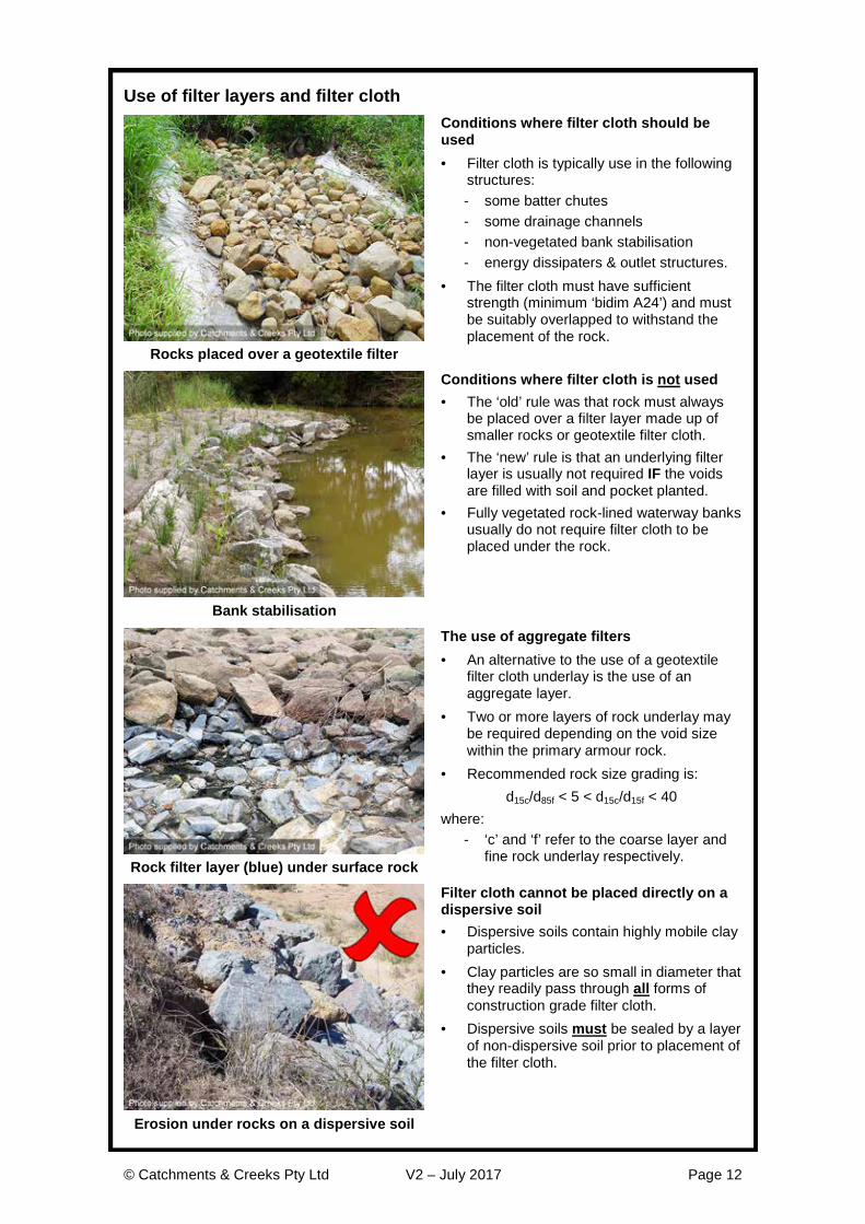
Use of filter layers and filter cloth
Conditions where filter cloth should be used · Filter cloth is typically use in the following
structures: - some batter chutes - some drainage channels - non-vegetated bank stabilisation - energy dissipaters & outlet structures.
· The filter cloth must have sufficient strength (minimum ‘bidim A24’) and must be suitably overlapped to withstand the placement of the rock.
Rocks placed over a geotextile filter
Conditions where filter cloth is not used · The ‘old’ rule was that rock must always
be placed over a filter layer made up of smaller rocks or geotextile filter cloth.
· The ‘new’ rule is that an underlying filter layer is usually not required IF the voids are filled with soil and pocket planted.
· Fully vegetated rock-lined waterway banks usually do not require filter cloth to be placed under the rock.
Bank stabilisation
The use of aggregate filters · An alternative to the use of a geotextile
filter cloth underlay is the use of an aggregate layer.
· Two or more layers of rock underlay may be required depending on the void size within the primary armour rock.
· Recommended rock size grading is: d15c/d85f < 5 < d15c/d15f < 40
where: - ‘c’ and ‘f’ refer to the coarse layer and
fine rock underlay respectively. Rock filter layer (blue) under surface rock
Filter cloth cannot be placed directly on a dispersive soil · Dispersive soils contain highly mobile clay
particles. · Clay particles are so small in diameter that
they readily pass through all forms of construction grade filter cloth.
· Dispersive soils must be sealed by a layer of non-dispersive soil prior to placement of the filter cloth.
Erosion under rocks on a dispersive soil

© Catchments & Creeks Pty Ltd V2 – July 2017 Page 13
Identification of dispersive and slaking soils
Dispersive and slaking soils · Dispersive soils are structurally unstable
when immersed in water, breaking down into their constituent particles (sand, silt and clay) thus allowing the dispersive clay fraction to disperse and cloud the water.
· ‘Slaking’ is the natural collapse of a soil aggregate in water when its mechanical strength is insufficient to withstand the swelling of clay and the expulsion of air from pore spaces—it does not include the effects of soil dispersion.
Collapse of a slaking soil in water
Identification of dispersive soils · Ideally, dispersive and slaking soils should
be identified through appropriate pre-construction soil testing, such as: - exchangeable sodium percentage > 6% - Emerson aggregate classes 1 to 5, note
classes 3(2), 3(1) and 5 also have a slight risk of dispersive problems.
· The ‘Aggregate Immersion Test’ is an on-site indicator of the soil properties.
· Dispersive soils may also be identified by their distinctive erosion patterns (left).
Fluting erosion in a dispersive soil
Aggregate immersion test · At best, soil tests conducted on-site can
only ‘indicate’ the existence of a potential soil problem.
· Such field tests are not a substitute for official soil sampling and testing.
· An aggregate immersion test (left) can be used as an indicator of potentially dispersive or slaking soils.
· Slaking soils (soils that readily collapse in water, but do not necessarily cloud the water) can be just as problematic.
Dispersion of a dispersive soil
Stabilisation of dispersive soils · Dispersive soils are highly susceptible to
deep, narrow rilling (fluting) on slopes and along the invert of drains.
· Dispersive soils must be treated (with gypsum or the like), or buried under a minimum 100 mm layer of non-dispersive soil before placing any vegetation or erosion control measures.
· Thicker (200–300 mm) capping with non-dispersive soil may be required on steep slopes and on the banks of waterways.
Fluting erosion in a dispersive soil

© Catchments & Creeks Pty Ltd V2 – July 2017 Page 14
The placement of rock over dispersive soils
Rock placed on dispersive or slaking soils · Rocks should not be placed directly onto
a dispersive (sodic) or slaking soil. · If the subsoils are dispersive/slaking, then
the work area (e.g. a batter chute) should be over-excavated, then topped with a 100 to 300 mm (min) layer of non-dispersive soil and covered with filter cloth prior to placement of the amour rock.
· The thickness of the non-dispersive soil layer depends on the likelihood of future bank disturbance.
Batter chute placed on a dispersive soil
Placement of rock on dispersive soils · Even ‘temporary’ batter chutes placed
directly on dispersive soils, such as this example, can experience significant damage during their short service life.
Failure of rock-lined batter chute
Grass-lined dam spillways · Erosion in dispersive soils typically results
in the formation of deep, steep-sided gullies that are usually deeper than they are wide.
· Dispersive soils often cause the total failure of farm dam spillways because landowners trust that the grass of rock lining will control the soil scour.
· If the soils directly below the grass or rock are dispersive, then tunnel and rill erosion is likely to occur.
Incised spillway in dispersive soil
Placement of grouted rock over dispersive soils · If loose or grouted rock is to be placed on
a dispersive (e.g. sodic) soil, then prior to placing the filter cloth, the exposed soil must first be covered with a layer of non-dispersive soil.
· It is noted that filter cloth, no matter how thick, cannot seal a dispersive soil, and thus should not be relied upon as the sole underlay for rock placed on a dispersive soil.
Grouted rock placed on dispersive soil

© Catchments & Creeks Pty Ltd V2 – July 2017 Page 15
Manning’s roughness of rock-lined surfaces
Manning’s equation · The average channel flow velocity may be
calculated using Manning’s equation:
V = (1/n) . R 2/3 . S ½ (2) where:
V = average flow velocity (m/s) n = Manning’s roughness coefficient R = hydraulic radius (m) = A/P A = effective flow area of channel (m 2) P = wetted perimeter of flow (m) S = channel slope (m/m)
Channel geometry and flow conditions
Factors affecting the hydraulic roughness of rock-lined surfaces · The effective Manning’s roughness of
rock-lined surfaces depends on: - average rock size (d50) - the distribution of rock sizes, defined in
this case by a ratio: d50/d90 - the depth of water flow, usually defined
by the hydraulic radius of flow (R) - the existence of vegetation - the occurrence of aerated ‘whitewater’
(not directly considered here). Gravel-based alluvial waterway
Manning’s roughness in deepwater · The Strickler formula for deepwater may
be presented in the modified form: n = ((d50)1/6 )/21.1 (3) · An alternative equation was developed by
Meyer-Peter & Muller: n = ((d90)1/6 )/26.0 (4)
- d50 = rock size for which 50% of rocks are smaller [m]
- d90 = rock size for which 90% of rocks are smaller [m]
Deepwater flow conditions
Manning’s roughness in shallow water · The Manning’s roughness (n) of rock-lined
surfaces in both shallow-water and deep-water flow conditions is provided below.
1/6
90m
dn26(1 0.3593 )
=-
(5)
- m = [(R/d90)(d50/d90)] 0.7 - R = hydraulic radius of flow [m]
· The relative roughness (d50/d90) of rock extracted from streambeds is typically in the range 0.2 to 0.5; while quarried rock is commonly in the range 0.5 to 0.8. Shallow water flow conditions

© Catchments & Creeks Pty Ltd V2 – July 2017 Page 16
Manning’s roughness of rock-lined surfaces The Manning’s (n) roughness for rock-lined surfaces can be determined from Table 1 or equation 5.
Table 1 – Manning’s (n) roughness of rock-lined surfaces
d50/d90 = 0.5 d50/d90 = 0.8
d50 = 200mm 300mm 400mm 500mm 200mm 300mm 400mm 500mm
R (m) Manning’s roughness (n) Manning’s roughness (n) 0.2 0.10 0.14 0.17 0.21 0.06 0.08 0.09 0.11 0.3 0.08 0.11 0.14 0.16 0.05 0.06 0.08 0.09 0.4 0.07 0.09 0.12 0.14 0.04 0.05 0.07 0.08 0.5 0.06 0.08 0.10 0.12 0.04 0.05 0.06 0.07 0.6 0.06 0.08 0.09 0.11 0.04 0.05 0.05 0.06 0.8 0.05 0.07 0.08 0.09 0.04 0.04 0.05 0.06 1.0 0.04 0.06 0.07 0.08 0.03 0.04 0.05 0.05
Equation 5 is considered to produce significantly better estimates of the Manning’s roughness of rock-lined surfaces in shallow water flow compared to the use of traditional deepwater equations such as the Strickler, Meyer-Peter & Muller or Limerinos equations.
Given the high variability of Manning’s n and the wide range of variables that are believed to influence the hydraulic roughness of a rock-lined channel, equation 5 is considered well within the limits of accuracy expected for Manning’s n selection.
Data analysis during the development of equation 5 indicated that the Meyer-Peter & Muller equation (eqn 4) produced more reliable estimates of the deepwater Manning's roughness values than the Strickler equation (eqn 3). Possibly the choice between the two equations would come down to how reliable the determination of the d50 and d90 values were. If the estimate of d90 is not reliable, then it would be more appropriate to rely on the Strickler equation for the determination of the deepwater Manning's n value, and visa versa.
Table 2 provides the range of data values used in the development of equation 5. This table also contains the data range for the selected variables for which the calculated Manning’s n value using equation 5 fall within +/-10% of the observed Manning’s n.
Table 2 – Data range used in determination of equation 5
d50 (mm) d90 (mm) R/d50 R/d90 no/n d50/d90 Min (+/-10%) 16 90 2.31 0.73 0.284 0.080 Max (+/-10%) 112 350 55.6 12.0 1.080 0.661 Min (All data) 16 90 1.17 0.31 0.097 0.080 Max (All data) 397 1080 66.9 12.9 1.120 0.661
Maximum bank gradient The recommended maximum desirable side slope of a large rock-lined chute is 1:2 (V:H); however, side slopes as steep as 1:1.5 can be stable if the rock is individually placed rather than bumped. Typical angles of repose for dumped rock are provided in Table 3.
Table 3 – Typical angle of repose for rock
Rock shape Angle of repose (degrees) Rock size > 100 mm Rock size > 500 mm
Very angular rock 41o 42o
Slightly angular rock 40o 41o
Moderately rounded rock 39o 40o

© Catchments & Creeks Pty Ltd V2 – July 2017 Page 17
Typical properties of rock Crushed rock is generally more stable than natural rounded rock; however, rounded rock has a more ‘natural’ appearance. A 36% increase in rock size is recommended if rounded rock is used (i.e. K1 = 1.36).
The rock should be durable and resistant to weathering, and should be proportioned so that neither the breadth nor the thickness of a single rock is less than one-third of its length.
Maximum rock size generally should not exceed twice the nominal (d50) rock size, but in some cases a maximum rock size of 1.5 times the average rock size may be specified.
Typical rock densities (sr) are presented in Table 4.
Table 4 – Relative density (specific gravity) of rock
Rock type Relative density (sr) Sandstone 2.1 to 2.4
Granite 2.5 to 3.1 (commonly 2.6) Limestone 2.6
Basalt 2.7 to 3.2 Table 5 provides a suggested distribution of rock sizes for waterway chutes. The distribution of rock size can also be described by the coefficient of uniformity, Cu = d60/d10, which usually falls in the range 1.1 to 2.70, but typically around 2.1. Witter & Abt (1990) reported that poorly graded rock (Cu = 1.1) has a critical discharge 8% greater than well-graded rock (Cu = 2.2).
Table 5 – Typical distribution of rock size for fish friendly structures (guide only)
Rock size ratio Assumed distribution value d100/d50 2.0 d90/d50 1.8 d75/d50 1.5 d65/d50 1.3 d40/d50 0.65 d33/d50 0.50 d10/d50 0.20
Thickness and height of rock layer The thickness of the armour layer should be sufficient to allow at least two overlapping layers of the nominal rock size. The thickness of rock protection must also be sufficient to accommodate the largest rock size. It is noted that increasing the thickness of the rock placement will not compensate for the use of undersized rock.
In order to allow at least two layers of rock, the minimum thickness of rock protection (T) can be approximated by the values presented in Table 6.
Table 6 – Minimum thickness (T) of rock lining
Min. thickness (T) Size distribution (d50/d90) Description 1.4 d50 1.0 Highly uniform rock size 1.6 d50 0.8 Typical upper limit of quarry rock 1.8 d50 0.67 Recommended lower limit of distribution 2.1 d50 0.5 Typical lower limit of quarry rock

© Catchments & Creeks Pty Ltd V2 – July 2017 Page 18
1. Bank Stabilisation

© Catchments & Creeks Pty Ltd V2 – July 2017 Page 19
Introduction
Introduction · Rock stabilisation has been one of the
most widely adopted techniques for the control of waterway bank erosion.
· To date its application has primarily been in the form of loosely dumped rock with voids left open; however, the practice of filling the voids with soil and pocket planting is becoming more common.
· Relevant fact sheet: http://www.catchmentsandcreeks.com.au/fact-sheets/esc_rock_sizing.html
Waterway bank stabilisation fact sheet
Factors affects rock size · The critical factors affecting rock size and
rock selection include: - flow velocity - degree of flow turbulence - bank slope - rock shape (round or angular) - rock density - void condition (open or filled) - degree and type of vegetation cover.
Bankful flow conditions
Short-term stability of rock-lined banks · Compared to most vegetated solutions,
rock stabilisation provides the benefit of instantaneous scour protection.
· However, in some circumstances it is desirable for vegetation to be established over the rocks; for example, when rock is placed on the outside of channel bends.
· This means, that during the initial years when the vegetation is not established over the rocks, some bank erosion problems can be expected immediately downstream of rock-stabilised area.
Bank erosion d/s of rock-stabilised bank
Long-term stability of rock-lined banks · Rock-protected waterway banks generally
exhibit good long-term stability, especially if suitable deep-rooted vegetation is established over the rocks.
· In dynamic waterways (i.e. waterways subject to active channel expansion or migration) rock stabilisation measures regularly fail over the long-term.
· Extra protection of the toe may be required if long-term bed lowering (bed erosion) is expected, especially on the outside of channel bends. Vegetated rock work

© Catchments & Creeks Pty Ltd V2 – July 2017 Page 20
Attributes of rock stabilised waterway banks
Aesthetics · Exposed rock can be unsightly. · Weed invasion of rock-protected surfaces
can also appear unsightly. · Better long-term aesthetics are usually
obtained when the rock-lined surface is fully vegetated with native plants.
· The use of broken concrete and building rubble for bank protection can be extremely unsightly, and is generally not recommended, especially in publicly accessible areas.
Poor aesthetics without vegetation cover
In-stream ecology · The battering of eroded banks for the
purpose of rock placement may result in the formation of an open-canopy, which may adversely affect water temperatures.
· The establishment of leafy vegetation along the water’s edge can be critical for aquatic fauna.
· Cavities around those rocks placed below the permanent water level can provide desirable aquatic habitat and shelter, especially if rocks smaller than 200 mm are removed from the rock mix.
Open voids below permanent waterline
Riparian habitat · Non-vegetated rock protection may create
surfaces with poor habitat diversity. · Establishing suitable vegetation over the
rock stabilisation can greatly improve the riparian habitat values.
· Rock protection can cause significant problems to burrowing fauna such as platypus—expert advice should be sought on such matters.
· Open voids above the water line can encourage vermin.
Bank stabilisation without revegetation
Importance of ‘habitat’ rock in waterways · Rock-lined surfaces can incorporate the
occasional feature rock or rock outcrop that provides habitat diversity and habitat attributes such as: - sunbaking/roosting for reptiles - protection of wildlife from predators - protection of wildlife from floods and
bushfire. · The occasional exposed rock surface can
also increase the effective channel roughness.
Lizard basking on exposed rock

© Catchments & Creeks Pty Ltd V2 – July 2017 Page 21
Attributes of rock stabilised waterway banks
Establishment of vegetation over rocks · The active establishment of a vegetative
cover over the rocks provides many benefits including: - increased stabilisation of the rocks - improved terrestrial habitat - improved aquatic habitat - improved fish passage conditions
during periods of high flow - improved aesthetics.
· Vegetated rock-lined banks can be viewed as a form of ‘soft engineering’.
Vegetated rock stabilisation works
Impact on waterway hydraulics · Non-vegetated rock stabilisation can
significantly reduce the hydraulic resistance of the watercourse potentially resulting in increased channel velocities and bed scour, but with the possible benefit of reduced flood levels.
· The hydraulic roughness of rock-lined waterways very much depends on the degree of vegetation cover.
· The inevitable establishment of vegetation over rock-lined surfaces can reduce the channel’s flow capacity.
Low-roughness rock-lined waterway
Waterway maintenance · Maintenance costs are usually related to
the desired long-term aesthetics of the waterway.
· The control of weed growth can be an expensive, labour-intensive exercise.
· Long-term maintenance is best controlled through the development of a canopy cover over the waterway to reduce weeds.
· Appropriate plant selection is the key to reducing maintenance costs, which requires the guidance of experts.
Waterway maintenance
Construction issues · Most structural bank failures result from
inappropriate placement of the rock, normally as a result of inadequate design detailing, inappropriate rock selection, or poor construction supervision.
· Rock-lined waterway structures are usually most susceptible to failure during the first two years of their operation, that is before sediment and vegetation have begun to stabilise the rocks.
Rock placement

© Catchments & Creeks Pty Ltd V2 – July 2017 Page 22
Critical design issues
Design velocity (Vdesign) adjacent banks · In grass-lined channels with a uniform
cross-section, adopt a design velocity equal to the calculated average flow velocity (Vdesign = Vaverage).
· In irregular, natural, woody/scrubby waterways, adopt a design velocity of two-thirds (67%) the average flow velocity.
· In all cases, on the outside of significant channel bends, adopt a design velocity adjacent to the outer bank of 133% of the average flow velocity (1.33 Vaverage).
Placement of rock on channel bends
Rock type and grading · Crushed rock is generally more stable
than natural rounded stone. · A 36% increase (i.e. K1 = 1.36) in rock
size is recommended for rounded rock. · Durable and resistant to weathering. · Neither the breadth nor the thickness of a
given rock less than one-third its length. · In most situations the nominal rock size is
usually between 200 mm to 600 mm. · Preferred grading provided on page 17.
Partial vegetated bank stabilisation
Recessing rock below the toe of bank · Extra rock may need to be placed below
bed level to: - prevent slippage of the upper rock - increase toe stability during floods
when short-term bed movement or bed lowing occurs during the flood peak
- allow the bank to adjust to long-term variations in bed level.
· If the above conditions do not exist, then the rock can rest of the channel bed (also see discussion on page 25).
Typical rock placement at toe of bank
Elevation of rock placement on banks · Rock placement often does not need to
extent to the top of the bank—refer to diagram above.
· A simple guide to rock placement: - straight reaches: 1/3 to 1/2 bank height - channel bends: 2/3 lowest bank height
on the outside of bends; and 1/3 the lowest bank height on inside of bends.
· In most cases, the upper bank area only needs to be stabilised with suitable vegetation.
Rock stabilisation on channel bend

© Catchments & Creeks Pty Ltd V2 – July 2017 Page 23
Critical design issues
Thickness of rock protection · The thickness of the armour layer should
be sufficient to allow at least two overlapping layers of the nominal rock size (refer to Table 6, page 17).
· The thickness of rock protection must also be sufficient to accommodate the largest rock size.
· It is noted that additional thickness will not compensate for the use of undersized rock.
Larger rocks forming toe protection
Backing material or filter layer · Non-vegetated armour rock must be
placed over a layer of suitably graded filter rock, or geotextile filter cloth.
· The geotextile filter cloth must have sufficient strength, and must be suitably overlapped, to withstand the placement of the rock (which normally results in movement of the fabric).
· Armour rock, that is intended to be vegetated by appropriately filling all voids with soil and pocket planting, will generally not require an underlying filter layer. Rock placement over filter cloth
Maximum bank slope · Maximum batter slope is typically 1:2
(V:H) for non-vegetated, and 1:2.5 (V:H) if vegetated—the flatter slope being desirable (but not essential) to provide safe conditions for planting operations.
· Steeper banks can be achieved with the use of slacked boulders, but the rocks must sit on a stable bed.
· Steep high banks can represent a safety hazard to revegetation teams—seek advice from revegetation contractors.
Stacked boulder wall
Establishment of vegetation · The establishment of vegetation over rock-
lined surfaces is generally encouraged. · Common revegetation problems that may
need to be addressed during the design phase include: - poor aesthetics due to poor plant
selection or weed invasion - steep banks that can be difficult to
maintain and weed - reduce hydraulic capacity of waterway if
woody species are establish within critical hydraulic areas. Vegetated rock stabilisation of bank

© Catchments & Creeks Pty Ltd V2 – July 2017 Page 24
Sizing of rock placement within low-gradient waterways
Equation 1.1 can be used to size rock placed on the bed of waterway channels. The same equation can be used for rock placed on waterway banks with slopes equal to or less than 1:2 (V:H), but a 25% increase in rock size should be applied for bank slopes of 1:1.5.
A 36% increase in rock size is recommended for rounded rock (i.e. K1 = 1.36). Application of Equation 1.1
· Simplified velocity-based equation suitable for uniform and non-uniform flow conditions [1]
· Low channel gradients, So < 5%
Equation 1.1
d K Vg K sr
501
2
22 1=
-.
. . ( ) (1.1)
K = 1.1 for low-turbulent deepwater flow K = 1.0 for low-turbulent shallow water flow K = 0.86 for highly turbulent flow (Table 1.1)
Note: Equation 1.1 represents a modification of the equation originally presented by Isbash (1936). The ‘K’ variable takes into account the degree of flow turbulence. Table 1.1 provides the recommended K-values for various uniform channel gradients (i.e. straight, uniform cross-sectional channels where a constant flow velocity is achieved). In non-uniform flow a K-value of 1.1 should be used for low-turbulent deepwater flow, 1.0 for low-turbulent shallow water flow, and 0.86 for highly turbulent and/or supercritical flow.
Table 1.1 – Suggested values of ‘K’ for uniform flow conditions
Bed slope (%) 1.0 2.0 3.0 4.0 5.0 6.0 8.0 10.0
K = 1.09 1.01 0.96 0.92 0.89 0.86 0.83 0.80
Flow conditions Low turbulence Ô Ô Ô Ô Ô Ô Ô Ô Ô Highly turbulent (whitewater) Note: Tabulated results are applicable to uniform flow conditions, and Manning’s n based on equation 5 (page 15). where:
d50 = nominal rock size (diameter) of which 50% of the rocks are smaller [m]
g = acceleration due to gravity [m/s2]
K = equation constant based on flow conditions
= 1.1 for low-turbulent deepwater flow, 1.0 for low-turbulent shallow water flow, and 0.86 for highly turbulent and/or supercritical flow (also refer to Table 1.1)
K1 = correction factor for rock shape
= 1.0 for angular (fractured) rock, 1.36 for rounded rock (i.e. smooth, spherical rock)
So = channel slope [m/m]
sr = specific gravity of rock (e.g. sandstone 2.1–2.4; granite 2.5–3.1, typically 2.6; limestone 2.6; basalt 2.7–3.2)
V = depth-averaged flow velocity at location of rock [m/s] Equation 1.1 reduces to the commonly used design equation (equation 1.2) for angular rock based on a rock specific gravity, sr = 2.6
d50 = 0.04 V 2 (1.2)

© Catchments & Creeks Pty Ltd V2 – July 2017 Page 25
Toe stabilisation of waterway banks
Toe erosion on channel banks · Toe erosion is common on constructed
channel banks if high flows occur during the plant establishment phase.
· Rock protection along the toe of newly formed or disturbed channel banks is usually necessary to provide short-term bank stabilisation during plant establishment.
· Without such rock protection, elevated stream flows can cause bank erosion before the plants are established.
Erosion along toe of bank
Toe stabilisation using rock · If flow velocities are low enough to allow
the use of vegetated banks, then the rock stabilisation of the toe usually only needs to extend about 0.5 to 1.0 m above the bed within ephemeral streams.
· The toe rock should integrate well into the bank soil and toe vegetation.
· The rock should not sit on the bank, but within the bank.
Rock stabilisation of bank toe
Recessing rock below the toe of bank · In most cases, rock stabilisation only
needs to extend below the bed level if: - the rock is placed on a steep bank, and
there is a risk of the rocks ‘slipping’ down the bank during floods
- deep movement of bed material (substrate) is likely during floods, or
- long-term lowering of the bed level (bed erosion) is likely to occur.
· Otherwise, the toe protection can rest on the channel bed.
Rock recessed below the channel bed
Alternative toe stabilisation measures · Coir or jute ‘geo logs’ can be used as an
alternative to rock stabilisation of the toe. · These geo logs typically provide only
temporary (less than 2-years) protection of the toe.
· These temporary protection measures are only successful if suitable vegetation is incorporated into, or around, the logs.
· It is important to ensure that bank erosion does not occur behind the logs during overtopping stream flows.
Coir ‘geo-log’ temporary toe protection

© Catchments & Creeks Pty Ltd V2 – July 2017 Page 26
Rock placement on banks
Advantages: Reduced quantity of rock.
Disadvantages: Problems can occur with lateral inflows (i.e. local stormwater runoff) entering into, or passing under, the rock. Can result in reduced aquatic habitat values in absence of vegetation.
Use: Ideally, the use of this rock placement method should be limited. Used on the inside face of fully shaded, high velocity channel bends. Rock placement with open voids
Advantages: Improved aquatic habitat values. Retention of riparian values.
Disadvantages: Care must be taken to ensure all voids are filled with soil to prevent loss (seepage) of upper bank soil into the rock layer.
Use: Toe protection of channel banks in regions of high flow velocity, or areas where the channel bed may experience scour. Generally the preferred method of rock placement within waterways.
Rock placement with soil-filled voids
Advantages: Very high scour protection once vegetation is established. Retention of aquatic habitat values. Retention of riparian values. Banks can be steeper than vegetated banks that do not contain rock protection.
Disadvantages: High installation cost.
Use: Outside face of high velocity or sharp channel bends. Also, areas where both the channel velocity and over-bank flow velocities are likely to be very high and thus erosive.
Full-height rock placement

© Catchments & Creeks Pty Ltd V2 – July 2017 Page 27
Rock placement on banks
Advantages: Cheaper installation cost compared to vegetated rock protection.
Disadvantages: Poor aesthetics. Poor aquatic habitat and fish passage. High risk of weed invasion unless fully shaded.
Use: Heavily shaded, high velocity areas. Outside face of fully shaded channel bends. Very high velocity regions where vegetation is not expected to survive. Full-height with open voids
Advantages: Long-term protection of highly erodible soils.
Disadvantages: Poor aesthetics. Poor aquatic habitat and fish passage. High risk of weed invasion unless fully shaded.
Use: Heavily shaded areas containing dispersive soils. Outside face of fully shaded channel bends. Very high velocity regions where vegetation is not expected to survive. Rock placement over dispersive soils
Advantages: Retention of aquatic habitat values. Long-term protection of highly erodible soils. Reduced maintenance costs.
Disadvantages: Higher installation cost compared to non-vegetated rock protection.
Use: Outside face of high velocity or sharp channel bends in dispersive soil regions. Dispersive soil areas where both the channel velocity and over-bank flow velocities are likely to be very high and therefore erosive.
Vegetated rock placement over poor soils

© Catchments & Creeks Pty Ltd V2 – July 2017 Page 28
Vegetated bank stabilisation works
Introduction · Wherever practical, rock protected areas
should be lightly covered with soil (to fill all voids) and pocket planted to encourage the preferred plant growth across the bank and along the water’s edge.
· In areas where revegetation is not desired (i.e. when hydraulically efficient channels are required for flood control) then the establishment or retention of an effective canopy cover (i.e. shade trees) is generally the preferred means of controlling weed growth.
Planted rock-stabilised creek bank
Infill soil · Experience has shown that minimal soil is
lost from the rock voids during flood events.
· The image presented left shows a recently planted bank that experienced a bankful flow just weeks after planting—all plants were lost from the bank, but most of the soil remained.
· Important: In order to allow proper plant growth, the infill soil needs to be placed progressively as the layers of rock are added to the bank.
Voids filled with soil ready for planting
Planting along the water’s edge · Wherever practical, vegetation should
extend to the water’s edge to increase the value and linkage of aquatic and terrestrial habitats.
· Plants that branch over the water’s edge can provide essential shading of the water to provide pockets of cool water for aquatic life.
· Edge plants also assist aquatic life to shelter from predators.
Planting along the water’s edge
Use of erosion control mats · During plant establishment it may be
necessary to mulch around newly placed plants to control soil moisture loss.
· Covering such areas with a jute or coir mesh can help to reduce the loss of mulch by wind and minor flows.
· However, it is noted that the compete loss of the matting during high flows can cause damage to, or the total loss of, any recently established plants.
Planted rock covered with jute mesh

© Catchments & Creeks Pty Ltd V2 – July 2017 Page 29
Stacked boulder walls
Stacked bounders · As the slope of a boulder wall increases,
an increasing proportion of the boulder weight rests on the lower boulders and ultimately the channel bed rather than on the channel bank.
· This means that if there is a significant flood and the creek bed erodes or weakens, then there is the risk that the entire boulder wall will slide down the face of the bank into the waterway.
Stacked boulder wall
Use of boulder walls · Stacked boulder walls can be used to:
- form steep banks that can allow the construction of, or protection of structural assets such as roads and pathways
- increase the stability of rock of a given size by increasing the vertical force placed on the rock as a result of the weight of the upper rock bearing down on the lower rocks.
Stacked small river gravel
Problems commonly associated with stacked boulder walls · In the absence of vegetation,
‘hydraulically’ smooth boulder walls can induce high flow velocities to occur adjacent the surface of the boulders.
· These same high velocities will also exist adjacent the creek bed, possibly causing bed scour.
· Toe erosion at the base of the boulder wall can caused the rocks to slide down the face of the bank into the waterway.
Stacked boulder wall
Importance of stable subsoil conditions · Unstable and/or dispersive subsoils can
cause the failure of staked boulder walls. · The stability of boulder walls can be
increased by incorporating earth reinforcing mesh into the wall and extending this mesh into the backfill.
Failed boulder wall

© Catchments & Creeks Pty Ltd V2 – July 2017 Page 30
Common problems associated with rock stabilisation of waterways
Failure to introduce suitable vegetation cover · The placement of loose rock on waterway
banks may initially appear as a ‘cheap’ option, but weed infestation can lead to ongoing maintenance costs.
· Wherever practical, rock-lined surfaces should be lightly covered with soil and appropriately planted with native species.
Rock placement without planting
Rock placement without planting Same location (left) after weed infestation
Placement of rock on sandy bed waterways · Sand-based waterways often contain a
deep bed of sand, which can liquefy during floods and move (flow) down the waterway like a viscous liquid.
· If heavy rocks are placed on the bed of a sand-based waterway, then these rocks may simply sink into the sand during flood events.
· The risk of the rocks displacing during floods depends on the depth of sand and its likely movement during floods.
Weak sandy bed structure after a flood
Rocks slipping down smooth filter cloth · In certain conditions, filter cloth effectively
acts as a low-friction surface, which can cause rocks to slowly slide down the face of a slope.
· If rocks need to be placed on steep slopes, then the rocks should be ‘keyed’ into the bank.
· Keying can be done by ‘stair-stepping’ the bank prior to placing the filter cloth.
Rocks displaced down filter cloth

© Catchments & Creeks Pty Ltd V2 – July 2017 Page 31
Common problems associated with rock stabilisation of waterways
Bank erosion at downstream end of rock-lined banks · In the absence of a vegetative cover, rock-
lined surfaces can act as ‘hydraulically’ smooth surfaces that can induce high flow velocities to exist adjacent the surface.
· These same high velocities can cause erosion on the unprotected waterway bank immediately downstream of the rock-lined surface.
· Erosion along the toe of the rock is also common.
Bank erosion at d/s end of rock work
Rock placed on dispersive or slaking soils · Rocks should not be placed directly onto
a dispersive, sodic, or slaking soil. · Tunnel erosion is a common occurrence
when rocks are placed directly on dispersive soils.
Tunnel erosion under rocks
Placement of rock over dispersive soils · If the rock is placed on a dispersive (e.g.
sodic) soil, then prior to placing the filter cloth, the exposed soil must first be covered with a layer of non-dispersive soil, typically minimum 200imm thickness, but preferably 300 mm.
· It is noted that filter cloth, no matter how thick, cannot seal a dispersive soil, and thus should not be relied upon as the sole underlay for rock placed on dispersive soil.
Collapsed dispersive soil bank
Rock not integrated into the bank · Rocks should not be placed on a creek
bank in a manner that detracts from the natural aesthetics of the waterway.
· Wherever possible, the rocks should be recessed into the soil, and appropriate native vegetation should be established over the rocks.
· The exception being when the establishment of vegetation would adversely affect local flood levels.
Poorly placed rocks on creek bank

© Catchments & Creeks Pty Ltd V2 – July 2017 Page 32
2. Culvert Bed Roughness
© Catchments & Creeks Pty Ltd V2 – July 2017 Page 33
Introduction
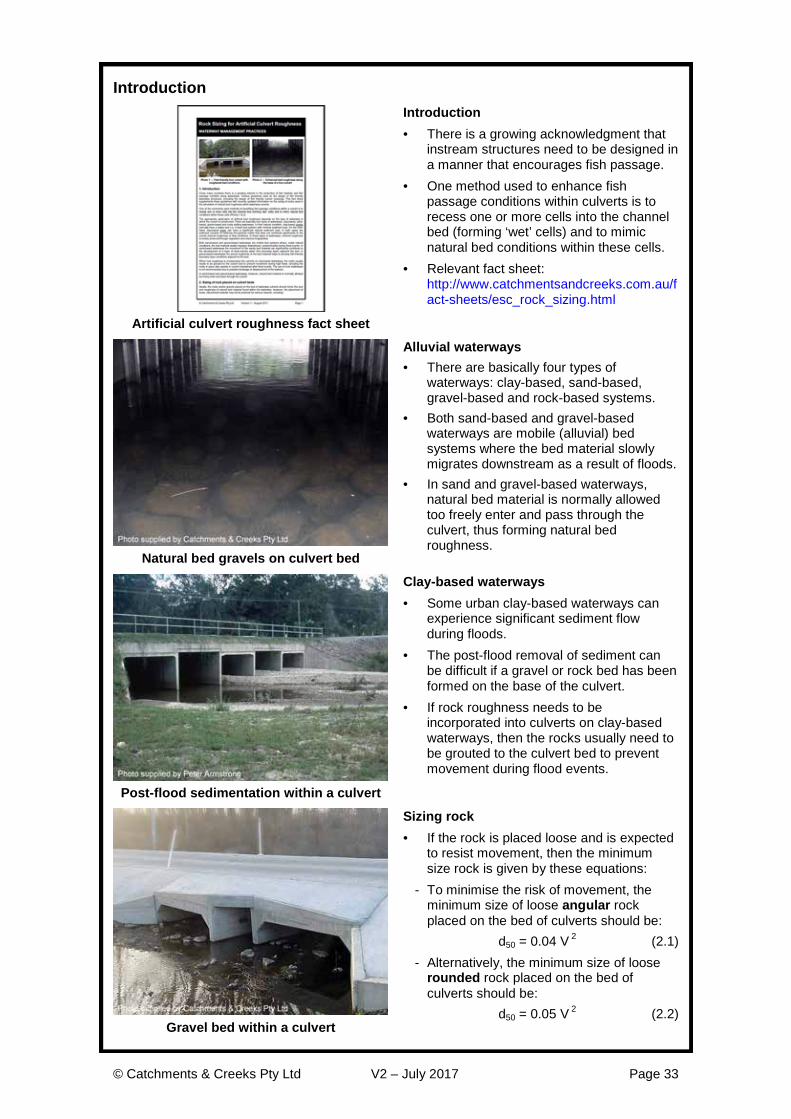
Introduction · There is a growing acknowledgment that
instream structures need to be designed in a manner that encourages fish passage.
· One method used to enhance fish passage conditions within culverts is to recess one or more cells into the channel bed (forming ‘wet’ cells) and to mimic natural bed conditions within these cells.
· Relevant fact sheet: http://www.catchmentsandcreeks.com.au/fact-sheets/esc_rock_sizing.html
Artificial culvert roughness fact sheet
Alluvial waterways · There are basically four types of
waterways: clay-based, sand-based, gravel-based and rock-based systems.
· Both sand-based and gravel-based waterways are mobile (alluvial) bed systems where the bed material slowly migrates downstream as a result of floods.
· In sand and gravel-based waterways, natural bed material is normally allowed too freely enter and pass through the culvert, thus forming natural bed roughness.
Natural bed gravels on culvert bed
Clay-based waterways · Some urban clay-based waterways can
experience significant sediment flow during floods.
· The post-flood removal of sediment can be difficult if a gravel or rock bed has been formed on the base of the culvert.
· If rock roughness needs to be incorporated into culverts on clay-based waterways, then the rocks usually need to be grouted to the culvert bed to prevent movement during flood events.
Post-flood sedimentation within a culvert
Sizing rock · If the rock is placed loose and is expected
to resist movement, then the minimum size rock is given by these equations:
- To minimise the risk of movement, the minimum size of loose angular rock placed on the bed of culverts should be:
d50 = 0.04 V 2 (2.1) - Alternatively, the minimum size of loose
rounded rock placed on the bed of culverts should be:
d50 = 0.05 V 2 (2.2) Gravel bed within a culvert

© Catchments & Creeks Pty Ltd V2 – July 2017 Page 34
Rock placement
Pipe culverts · Wet cell pipe culverts are typically
recessed 20% of their diameter. · Recessing the culvert cells will reduce the
effective flow area (A), wetted perimeter (P), hydraulic radius (R) and pipe roughness (n).
· Hydraulic parameters for a pipe culverts flowing full and recessed 20% into the channel bed are provided in tables 2.1 to 2.4 for various rock size distributions (d50/d90).
Natural bed material in a pipe culvert
Box culverts · Wet cell box culverts are typically
recessed 20% of the cell height or at least 300 mm.
· Hydraulic parameters for a box culverts flowing full and recessed 20% into the channel bed are provided in tables 2.5 and 2.6 for various rock size distributions.
· If grouted rocks are used, then the installation costs may be reduced by grouting the rock onto the bed prior to placement of the box units.
Rocks grouted to bed of box culvert
Post flood de-silting of culverts · Some culverts regularly require the
removal of sediments deposited during flood events.
· The removal of sediment from culverts can cause the disturbance or total removal of any introduced rock roughness.
· If the culvert and the raised benching is appropriately sized, then ‘bobcats’ can used to facilitate the removal of excessive sediment deposits and the general maintenance of the culvert.
Post-flood sediment removal from culvert
Use of rock mattresses · The use of ‘rock mattresses’ as a form of
bed roughness is not recommended due to possible breakage or displacement of the baskets.
· These mattresses have been known to move and block culverts during flood events.
Rock mattress placed on culvert bed

© Catchments & Creeks Pty Ltd V2 – July 2017 Page 35
Hydraulic properties of pipe culverts containing artificial bed roughness The placement of rocks and gravels on the bed of pipe culverts will alter the overall hydraulic roughness of the conduit. Tables 2.1 to 2.4 provide the hydraulic parameters for various pipe culvert conditions. These tables are based on an assumed smooth wall Manning’s roughness (n) of 0.013.
Hydraulic properties of box culverts containing artificial bed roughness Tables 2.5 and 2.6 provide the hydraulic parameters for various box culvert conditions. These tables are based on an assumed smooth wall Manning’s roughness, n = 0.013.
The placement of loose rock is most appropriate in gravel-based waterways that experience a regular movement of similar sized rocks down the stream. Loose rock can also be used in clay-based streams (if sediment flow down the stream is negligible) however, grouted rock may be required to avoid loss of the rocks during flood events.
If grouted rocks are used, then the cost of their installation may be reduced by grouting the rocks onto the base slab prior to installation of the pre-cast units. Grouted rocks are likely to have a slightly lower Manning’s roughness to that of loosely placed rocks.
If loosely placed rocks are used, then consideration should be given to the placement of a raised sill at the downstream end of the culvert to help retain the rocks during high flows.
Benching is normally only used in single cell box culverts when it is necessary to provide both wet (aquatic) passage and dry (terrestrial) passage. If it is desirable for natural bed material to form across the bed of the culvert, then the height of the benching must be sufficient to allow a dry path to exist during normal base flow conditions.
If the culvert and the raised benching is appropriately sized, then ‘bobcats’ can travel along the raised benching to facilitate the removal of excessive sediment deposits, and the general maintenance of the culvert.
Table 2.1 – Pipe full hydraulic parameters for a pipe culvert recessed 20% into the
channel bed with a loose or grouted rock bed and d50/d90 = 0.2
Mean bed rock size d50 = 50 mm 100 mm 200 mm 300 mm 400 mm
D (mm) A (m2) P (m) R (m) Pipe full Manning’s roughness (n)
450 0.136 1.356 0.101 0.06
525 0.192 1.610 0.119 0.05 0.09
600 0.251 1.839 0.136 0.05 0.08
750 0.391 2.297 0.170 0.05 0.07
825 0.473 2.526 0.187 0.04 0.07
900 0.564 2.758 0.204 0.04 0.07
1050 0.765 3.213 0.238 0.04 0.06 0.10
1200 1.001 3.674 0.272 0.04 0.06 0.09
1350 1.268 4.136 0.307 0.04 0.05 0.09
1500 1.564 4.594 0.341 0.034 0.05 0.08 0.11
1650 1.892 5.052 0.375 0.032 0.05 0.08 0.10
1800 2.251 5.510 0.408 0.031 0.05 0.07 0.10
2100 3.143 6.511 0.483 0.029 0.04 0.07 0.09 0.11

© Catchments & Creeks Pty Ltd V2 – July 2017 Page 36
Table 2.2 – Pipe full hydraulic parameters for a pipe culvert recessed 20% into the
channel bed with a loose or grouted rock bed and d50/d90 = 0.3
Mean bed rock size d50 = 50 mm 100 mm 200 mm 300 mm 400 mm
D (mm) A (m2) P (m) R (m) Pipe full Manning’s roughness (n) 450 0.136 1.356 0.101 0.038 525 0.192 1.610 0.119 0.035 0.05 600 0.251 1.839 0.136 0.033 0.05 750 0.391 2.297 0.170 0.031 0.04 825 0.473 2.526 0.187 0.029 0.04 900 0.564 2.758 0.204 0.029 0.04
1050 0.765 3.213 0.238 0.027 0.04 0.06 1200 1.001 3.674 0.272 0.026 0.04 0.06 1350 1.268 4.136 0.307 0.025 0.035 0.05 1500 1.564 4.594 0.341 0.024 0.033 0.05 0.06 1650 1.892 5.052 0.375 0.024 0.032 0.05 0.06 1800 2.251 5.510 0.408 0.023 0.031 0.05 0.06 2100 3.143 6.511 0.483 0.022 0.029 0.04 0.05 0.06
Table 2.3 – Pipe full hydraulic parameters for a pipe culvert recessed 20% into the
channel bed with a loose or grouted rock bed and d50/d90 = 0.5
Mean bed rock size d50 = 50 mm 100 mm 200 mm 300 mm 400 mm
D (mm) A (m2) P (m) R (m) Pipe full Manning’s roughness (n) 450 0.136 1.356 0.101 0.024 525 0.192 1.610 0.119 0.023 0.032 600 0.251 1.839 0.136 0.022 0.030 750 0.391 2.297 0.170 0.021 0.028 825 0.473 2.526 0.187 0.021 0.027 900 0.564 2.758 0.204 0.020 0.026
1050 0.765 3.213 0.238 0.020 0.025 0.034 1200 1.001 3.674 0.272 0.019 0.024 0.032 1350 1.268 4.136 0.307 0.019 0.023 0.031 1500 1.564 4.594 0.341 0.019 0.023 0.030 0.037 1650 1.892 5.052 0.375 0.018 0.022 0.029 0.035 1800 2.251 5.510 0.408 0.018 0.022 0.028 0.034 2100 3.143 6.511 0.483 0.018 0.021 0.027 0.032 0.037
Table 2.4 – Pipe full hydraulic parameters for a pipe culvert recessed 20% into the
channel bed with a loose or grouted rock bed and d50/d90 = 0.8
Mean bed rock size d50 = 50 mm 100 mm 200 mm 300 mm 400 mm
D (mm) A (m2) P (m) R (m) Pipe full Manning’s roughness (n) 450 0.136 1.356 0.101 0.019 525 0.192 1.610 0.119 0.018 0.022 600 0.251 1.839 0.136 0.018 0.021 750 0.391 2.297 0.170 0.017 0.020 825 0.473 2.526 0.187 0.017 0.020 900 0.564 2.758 0.204 0.017 0.020
1050 0.765 3.213 0.238 0.017 0.019 0.024 1200 1.001 3.674 0.272 0.017 0.019 0.023 1350 1.268 4.136 0.307 0.016 0.019 0.022 1500 1.564 4.594 0.341 0.016 0.018 0.022 0.025 1650 1.892 5.052 0.375 0.016 0.018 0.021 0.024 1800 2.251 5.510 0.408 0.016 0.018 0.021 0.024 2100 3.143 6.511 0.483 0.016 0.018 0.020 0.023 0.025

© Catchments & Creeks Pty Ltd V2 – July 2017 Page 37
Table 2.5 – Manning’s roughness for rock lined channels in shallow water
d50/d90 d50/d90 = 0.2 d50/d90 = 0.3
d50 (mm)
50 100 200 300 400 50 100 200 300 400
R (mm) Channel bed Manning’s roughness (n) Channel bed Manning’s roughness (n)
200 0.12 0.21 0.38 0.53 0.67 0.07 0.12 0.21 0.37 0.37
300 0.10 0.17 0.30 0.40 0.51 0.06 0.10 0.16 0.28 0.28
400 0.08 0.14 0.24 0.33 0.42 0.05 0.08 0.14 0.23 0.23
500 0.07 0.12 0.21 0.29 0.37 0.05 0.07 0.12 0.20 0.20
600 0.07 0.11 0.19 0.26 0.32 0.04 0.07 0.11 0.18 0.18
700 0.06 0.10 0.17 0.23 0.29 0.04 0.06 0.10 0.17 0.17
800 0.06 0.09 0.16 0.21 0.27 0.04 0.06 0.09 0.15 0.15
900 0.06 0.09 0.15 0.20 0.25 0.04 0.06 0.09 0.14 0.14
1000 0.05 0.08 0.14 0.19 0.23 0.04 0.05 0.08 0.13 0.13
1200 0.05 0.08 0.12 0.17 0.21 0.03 0.05 0.07 0.12 0.12
1400 0.05 0.07 0.11 0.15 0.19 0.03 0.05 0.07 0.11 0.11
1600 0.04 0.07 0.10 0.14 0.18 0.03 0.04 0.06 0.10 0.10
1800 0.04 0.06 0.10 0.13 0.16 0.03 0.04 0.06 0.10 0.10
2000 0.04 0.06 0.09 0.12 0.15 0.03 0.04 0.06 0.09 0.09
Table 2.6 – Manning’s roughness for rock lined channels in shallow water
d50/d90 d50/d90 = 0.5 d50/d90 = 0.8
d50 (mm)
50 100 200 300 400 50 100 200 300 400
R (mm) Channel bed Manning’s roughness (n) Channel bed Manning’s roughness (n)
200 0.04 0.06 0.10 0.14 0.17 0.03 0.04 0.06 0.08 0.09
300 0.04 0.05 0.08 0.11 0.14 0.03 0.03 0.05 0.06 0.08
400 0.03 0.05 0.07 0.09 0.12 0.03 0.03 0.04 0.05 0.07
500 0.03 0.04 0.06 0.08 0.10 0.03 0.03 0.04 0.05 0.06
600 0.03 0.04 0.06 0.08 0.09 0.03 0.03 0.04 0.05 0.05
700 0.03 0.04 0.05 0.07 0.09 0.03 0.03 0.04 0.04 0.05
800 0.03 0.04 0.05 0.07 0.08 0.03 0.03 0.04 0.04 0.05
900 0.03 0.04 0.05 0.06 0.08 0.03 0.03 0.04 0.04 0.05
1000 0.03 0.03 0.05 0.06 0.07 0.03 0.03 0.03 0.04 0.05
1200 0.03 0.03 0.04 0.06 0.07 0.03 0.03 0.03 0.04 0.04
1400 0.03 0.03 0.04 0.05 0.06 0.03 0.03 0.03 0.04 0.04
1600 0.03 0.03 0.04 0.05 0.06 0.03 0.03 0.03 0.04 0.04
1800 0.03 0.03 0.04 0.05 0.06 0.03 0.03 0.03 0.04 0.04
2000 0.03 0.03 0.04 0.05 0.05 0.03 0.03 0.03 0.04 0.04

© Catchments & Creeks Pty Ltd V2 – July 2017 Page 38
3. Culvert Outlet Structures

© Catchments & Creeks Pty Ltd V2 – July 2017 Page 39
Introduction
Introduction · Similar hydraulic forces exist at the outlets
of multi-cell culverts and multi-pipe drainage systems.
· The hydraulic forces generated by multiple cell outlets are generally higher than those expected at single cell outlets.
· Consequently the rock sizing charts are different for multi and single cell outlets.
· Relevant fact sheet: http://www.catchmentsandcreeks.com.au/fact-sheets/esc_rock_sizing.html
Multi-pipe and culvert outlet fact sheet
Critical design parameters · The critical design parameters for multi-
cell outlet structures are the mean rock size (d50) and length of rock protection (L).
· The primary performance objectives are to: - minimise the risk of soil erosion
downstream of the outlet, and - prevent soil erosion adjacent the outlet
that could potentially undermine the culvert.
Culvert outlet scour protection
Length of the rock pad · The specified minimum pad length (L) is
based on practicality issues and will not necessarily prevent all bed scour.
· During high tailwater conditions, or when the culvert is operating under ‘outlet control’ conditions, bed and bank erosion can occur well downstream of the outlet.
· When the outlet is fully or partially drowned (i.e. high tailwater) then ‘jetting’ from the outlet can transfer energy well downstream of the rock pad.
Multi-cell box culvert outlet
Ongoing movement of rock · The rock sizing design charts and tables
presented in this section are based on the acceptance that some degree of rock movement (rearrangement) will likely occur during the first few years following installation.
· Also, some degree of bed scour may also occur downstream of the rock pad during major discharges.
Movement of rocks within rock pad

© Catchments & Creeks Pty Ltd V2 – July 2017 Page 40
Hydraulics of culvert outlets
Outlet flow conditions · The hydraulics of culvert outlets change
with changing tailwater conditions. · Some design guidelines provide different
rock pad outlet dimensions for low tailwater conditions and high tailwater conditions.
· The different hydraulic conditions of low and high tailwater are discussed below.
Culvert discharge with very low tailwater
Low tailwater flow conditions · During low tailwater conditions, discharges
tend to ‘spill’ from the culvert cells spreading the flow energy over a wider pathway than during high tailwater.
· Energy dissipation is much more efficient and the required length of the rock pad is smaller than is required during high tailwater conditions.
· The rock pad lengths (L) presented within the following pages typically reflect this low tailwater condition.
Culvert discharge with low tailwater
High tailwater flow conditions · During high tailwater conditions,
discharges from the cells tend to ‘float’ along the surface of the water.
· During these conditions it is common for high velocity outlet jets to travel a distance of between 10 and 15 times the jet depth (i.e. approx twice the nominal rock pad length, L) before there is a significant reduction in the central core flow velocity.
· The existence of a rock pad may not necessarily enhance energy dissipation.
Outlet jetting during high tailwater
Purpose of head walls on culvert outlets · Head walls can provide the following
benefits: - reduce the risk of erosion undermining
the outlet (if a cut-off wall is included) - reduce the risk of rock displacement
within outlet structures - reduce the risk of ‘entrained vortices’
eroding the channel banks adjacent the outlet.
Example of entrained outlet vortices

© Catchments & Creeks Pty Ltd V2 – July 2017 Page 41
Sizing rock downstream of culvert outlets Recommended mean (d50) rock sizes are presented in tables 3.2 and 3.3. These values have been rounded up to the next 100 mm increment in consideration of the limited availability of rock sizes and the high variability of expected outcomes.
Mean rock sizes are also presented graphically in Figure 3.1. Some minor variations should be expected between Figure 3.1 and the tabulated values.
A 36% increase in rock size is recommended if rounded rocks are used instead of angular rock.
The recommended minimum length of rock protection (L) is presented in tables 3.4 and 3.5. A typical layout of the rock pad is shown in Figure 3.2. The rock pad should be straight and aligned with the direction of outflow.
The recommended minimum width of the rock pad, W = B + 0.6 (Figure 3.2) is presented as a guide only. In most cases the width of rock protection is likely to be limited by the width of the receiving channel.
In circumstance where the width of the rock pad is governed by the width of the receiving channel, then the rock protection may need to extend partially up the banks of the channel if suitable vegetation cannot be established on the channel banks.
Figure 3.1 – Sizing of rock pad outlet structures for multi-pipe and box culvert outlets
The thickness of the rock pad should be based on at least two layers of rock. This typically results in an overall pad thickness as presented in Table 3.1.
Table 3.1 – Minimum thickness (T) of rock pad
Min. thickness (T) Size distribution (d50/d90) Description 1.4 d50 1.0 Highly uniform rock size 1.6 d50 0.8 Typical upper limit of quarry rock 1.8 d50 0.67 Recommended lower limit of distribution 2.1 d50 0.5 Typical lower limit of quarry rock
Note: dX = nominal rock size (diameter) of which X% of the rocks are smaller.

© Catchments & Creeks Pty Ltd V2 – July 2017 Page 42
Figure 3.2 – Typical layout of a rock pad for multiple pipe and box culverts (plan view)
The surface elevation of the downstream end of the rock pad should be level with the invert of the receiving channel, i.e. the rocks should be recessed into the outlet channel (Figure 3.3) to minimise the risk of erosion around the outer edges of the rock pad.
The placement of filter cloth under the rock pad is generally considered mandatory for all permanent structures; however, if heavy sedimentation is expected within the rock voids, then the ‘need’ for the filter cloth is reduced. The placement of filter cloth is essential in circumstances where it is only practical to place a single layer of rock.
Selecting the appropriate length of rock protection In circumstances where it is essential to minimise the risk of bed scour downstream of the culvert, then the length of the rock pad should be twice that presented in tables 3.4 and 3.5; however, little value is gained from extending the rock protection any further.
When the outlet is submerged (TW > H) a floating outlet ‘jet’ can pass over the rock pad with minimal energy loss. In such cases the rock pad still provides essential scour protection adjacent the culvert, but extending the rock protection beyond the nominated minimum length may not necessarily provide any significant increase in energy dissipation or scour protection.
High velocity outlet jets can cause bank erosion problems if the outlet is aimed at a downstream embankment. Typically, such problems only occur if an unprotected embankment is less than 13 times the pipe diameter or cell depth away from the multi-cell outlet.
Figure 3.3 – Rock pad recessed into the receiving channel

© Catchments & Creeks Pty Ltd V2 – July 2017 Page 43
Table 3.2 – Mean rock size, d50 (mm) for culvert outlet scour protection
Outflow velocity
(m/s)
Culvert height or pipe diameter (mm)
300 375 450 525 600 750 900
0.50 100 100 100 100 100 100 100 1.00 100 100 100 100 100 100 100 1.50 100 100 100 100 100 200 200 2.00 200 200 200 200 200 200 200 2.50 200 200 200 200 200 200 200 3.00 300 300 300 300 300 300 300 3.50 300 400 400 400 400 400 400 3.75 300 400 400 400 400 400 400 4.00 300 400 500 500 500 500 500 4.25 300 400 500 500 500 500 500 4.50 300 400 500 600 600 600 600 4.75 300 400 500 600 600 600 600 5.00 300 400 500 600 600 700 700 5.25 300 400 500 600 600 800 800 5.50 300 400 500 600 600 800 800 5.75 300 400 500 600 600 800 871 6.00 300 400 500 600 600 800 900
Table 3.3 – Mean rock size, d50 (mm) for culvert outlet scour protection
Outflow velocity
(m/s)
Culvert height or pipe diameter (mm)
1050 1200 1350 1500 1800 2100 2400
0.50 100 100 100 100 100 100 100 1.00 100 100 200 200 200 200 200 1.50 200 200 200 200 200 300 300 2.00 200 200 200 200 300 300 300 2.50 200 300 300 300 300 400 400 3.00 300 300 300 300 400 500 500 3.50 400 400 400 400 500 500 500 3.75 400 400 400 400 500 500 600 4.00 500 500 500 500 500 600 600 4.25 500 500 500 500 600 600 600 4.50 600 600 600 600 600 600 600 4.75 600 600 600 600 600 600 700 5.00 700 700 700 700 700 700 700 5.25 900 900 900 900 900 900 900 5.50 900 900 900 900 900 900 900 5.75 900 900 900 900 900 900 900 6.00 1000 1000 1000 1000 1000 1000 1000

© Catchments & Creeks Pty Ltd V2 – July 2017 Page 44
Table 3.4 – Minimum length (L) of rock pad relative to cell height (H) for culvert outlet protection [1,2]
Outflow velocity
(m/s)
Culvert height or pipe diameter (mm)
300 375 450 525 600 750 900 0.50 3 3 3 3 3 3 3 1.00 3 3 3 3 3 3 3 1.50 3 3 3 3 3 3 3 2.00 3 3 3 3 3 3 3 2.50 3 3 3 3 3 3 3 3.00 3 3 3 3 3 3 3 3.50 3 3 3 3 3 4 4 3.75 3 3 3 3 4 4 4 4.00 3 3 3 4 4 4 4 4.25 3 3 4 4 4 4 4 4.50 3 4 4 4 4 4 4 4.75 3 4 4 4 4 4 5 5.00 4 4 4 4 4 4 5 5.25 4 4 4 4 4 5 5 5.50 4 4 4 6 6 6 6 5.75 4 4 6 6 6 6 6 6.00 4 6 6 6 6 6 6
Table 3.5 – Minimum length (L) of rock pad relative to cell height (H) for culvert outlet protection [1,2]
Outflow velocity
(m/s)
Culvert height or pipe diameter (mm)
1050 1200 1350 1500 1800 2100 2400 0.50 3 3 3 3 3 3 3 1.00 3 3 3 3 3 3 4 1.50 3 3 3 3 3 4 4 2.00 3 3 3 3 4 4 4 2.50 3 4 4 4 4 4 4 3.00 4 4 4 4 4 4 4 3.50 4 4 4 4 5 5 5 3.75 4 4 4 4 5 5 5 4.00 4 4 5 5 5 5 5 4.25 4 5 5 5 5 5 5 4.50 5 5 5 5 5 5 5 4.75 5 5 5 5 5 5 5 5.00 5 5 5 5 6 6 5.25 6 6 6 6 6 6 5.50 6 6 6 6 6 5.75 6 6 6 6 6 6.00 6 6 6 6 6
[1] Values represent the recommended minimum length of rock protection to prevent significant scour; however, some degree of soil erosion should be expected downstream of the rock protection.
[2] Under high tailwater conditions (TW > D/2) outlet jetting may extend beyond the rock protection during high tailwater conditions resulting in bed and/or bank erosion downstream of the rock protection. Extending the length of the rock protection will not necessarily reduce the risk of downstream bank erosion under high tailwater conditions.

© Catchments & Creeks Pty Ltd V2 – July 2017 Page 45
Common construction problems
Inadequate rock size · Rock of inadequate size can readily be
displaced downstream of the culvert causing erosion to threaten the culvert.
Placement on dispersive soils (below) · Outlet scour protection often fails when
placed directly on a dispersive soil. · The formation of a cut-off wall at the
downstream end of the concrete apron can reduce the risk of structural failure, especially if placed on dispersive soils.
Displacement of rock pad
Undermining of culvert Same culvert outlet eight years later
Poor placement of rock · If the rock sits above the invert of the
culvert, then: - sediment is likely to collect within the
culvert, and - the outlet ‘jet’ can be deflected towards
the creek banks by the rocks. · The rocks need to be recessed such that
the upper surface of the rocks is level with the concrete apron.
Inappropriate rock placement
Outlet jetting · During periods of high tailwater, or when
the culverts is operating under ‘outlet control’ conditions, the outlet jet can float along the water surface within minimal energy dissipation.
· Floating outlet jets can travel at speed around 10 to 15 times their diameter (pipe culverts) or effective flow depth (box culverts) depending on the exit velocity and the spacing between the culvert cells.
Bank erosion well downstream of culvert

© Catchments & Creeks Pty Ltd V2 – July 2017 Page 46
4. Waterway and Gully Chutes

© Catchments & Creeks Pty Ltd V2 – July 2017 Page 47
Introduction
Reference document · In waterways, the terms ‘chutes’ and
‘ramps are generally interchangeable. · The term ‘chute’ is more commonly used
by hydraulic engineers, while the term ‘ramp’ is more commonly used by fishery officers.
· Relevant fact sheet: http://www.catchmentsandcreeks.com.au/fact-sheets/esc_rock_sizing.html
Waterway and gully chute fact sheet
Waterway chutes · A ‘waterway chute’ is a stabilised section
of waterway used to control bed erosion while maintaining desirable fish passage conditions in a manner similar to a natural riffle.
· These structures may also be referred to as ‘Grade Control Structures’ or ‘Rock Ramps’.
· A ‘ridge rock fishway’ is similar to a rock ramp; however, the sizing and placement of the rock is different.
Waterway chute
Gully chutes · A ‘gully chute’ is a steep drainage
channel, typically of uniform cross-section, used to stabilise the head of a gully, or to control flow into, or out of, a gully.
· The main design different between waterway chutes and gully chutes is that gully chutes rarely need to be fish-friendly because these ‘dry’ gullies are rarely recognised as viable fish habitats.
· In effect, gully chutes are just large versions of a drainage batter chute.
Gully chute
High failure risk · Rock-lined chutes are considered high-risk
waterway structures because they have a relatively high structural failure rate, especially within the first few years after construction.
· Structural failure can occur either through the direct displacement of the rocks by water flow, or the undermining of the structure as a result of downstream erosion or flows bypassing either under or around the rocks.
Failed gully chute

© Catchments & Creeks Pty Ltd V2 – July 2017 Page 48
Key design considerations
Critical design issues · Critical design components of a chute are:
- flow entry into the chute - the maximum allowable flow velocity
down the face of the chute - energy dissipation at base of chute.
· Most chutes fail as a result of rock displacement; therefore, it is critical to size the rocks using rock properties (e.g. rock density, size distribution and shape) that are representative of the rocks actually used within the structure.
Waterway/gully chute hydraulics
Design of chute inlet · Flow conditions upstream of the chute
may be determined using an appropriate weir equation.
· It is important to ensure that the water level upstream of the chute does not cause undesirable flooding (of adjacent land) or flow bypassing around the edges of the rock-lined chute.
Trapezoidal weir geometry
Design of the face of the chute · Determination of the mean rock size for
use on the face of the chute can be based on either the unit flow rate (equations 4.1 & 4.2) or the estimated flow velocity (equations 4.3 & 4.4) down the chute.
· To the maximum degree practicable, the crest and face of the chute should be designed to achieve near-uniform flow conditions across the width of the chute, thus minimising 3-dimensional flow patterns.
Defining the unit flow rate (q)
Design of the chute outlet and energy dissipation · Suitable energy dissipation is required at
the base of the chute. · The design of energy dissipaters must be
assessed on a case-by-case basis. · The type and extent of scour control within
the energy dissipater depends on: - the fall height of the chute - the expected tailwater conditions, and - whether or not the energy dissipation
basin can be recessed into the bed. Energy dissipation basin for a chute

© Catchments & Creeks Pty Ltd V2 – July 2017 Page 49
Design features
Fish passage · Studies of natural riffles indicate that the
desirable maximum fall of a fish-friendly chute or rock ramp is around 500 mm.
· It is noted that constructing fish-friendly chutes from large rocks (> 500 mm) can be problematic.
· The maximum recommended rock size (d50) is 600 mm due to the difficulties of both obtaining larger rock, and the difficulties of placing such rock within natural waterways.
Looking ‘down’ a rock ramp fishway
Chute fall and gradient · Chute gradients flatter than 1 in 6 are
inherently much more stable, safer and fish friendly in comparison to steeper bed slopes.
· If the chute is required to be fish friendly, then a gradient of between 1 in 20 and 1 in 30 is normally specified.
· For reasons of stability, the fall height should be limited to 1200 mm; however, fish passage requirements generally limit the fall of individual chutes to 500 mm.
Constructed waterway riffle
Use of low-flow channels · The placement of a low-flow channel
through a rock chute should be avoided. · In most cases, trickle flows simply pass
between the voids of the larger rocks, thus negating the need for a formal low-flow channel.
· The problem caused by the existence of a low-flow channel is that it can significantly increase the required rock size due to increased shear stress, often requiring the rocks to be grouted in place.
Low-flow channel set in grouted rock
Formation of a low-flow channel through the weir crest · If a low-flow channel must pass through
the structure, then the depth of this channel should be minimised, especially at the crest of the chute.
· Typically the rocks around a low-flow channel need to be grouted in place to obtain the necessary stability and desirable flow conditions.
· The use of grouted rock within natural waterways should be avoided wherever possible. Low-flow channel set in grouted rock

© Catchments & Creeks Pty Ltd V2 – July 2017 Page 50
Sizing rock for the face of waterway and gully chutes
Application of equation 4.1
· Preferred design equation
· Applicable for uniform flow conditions only, Se = So
· Batter slopes (So) less than 50% (1 in 2)
Equation 4.1:
d SF K K S q ys
o
r50
1 20 5 0 5 0 25127
1=
-. . . . . . .
( )
. . .
Application of equation 4.2
· A simplified equation independent of flow depth
· Applicable for uniform flow conditions only, Se = So
· Batter slopes (So) less than 50% (1 in 2)
Equation 4.2:
d SF K K S qs
o
r50
1 20 47 0 64
1=
-. . . .
( )
. .
Application of equation 4.3
· A simplified, velocity-based equation
· Applicable for uniform flow conditions only, Se = So
· Batter slopes (So) less than 33% (1 in 3)
Equation 4.3:
d SF K K VA B S so r
501 2
2
1=
- -. . .
( .ln( )).( )
For SF = 1.2: A = 3.95, B = 4.97
For SF = 1.5: A = 2.44, B = 4.60
Application of equation 4.4
· Suitable for use in the design of partially drowned waterway chutes
· Applicable for steep gradient, non-uniform flow conditions, Se ≠ So
· Batter slopes (So) less than 50% (1 in 2)
Equation 4.4:
d SF K K S V yV s
o
o r50
1 20 5 2 5 0 75
2 0127
1=
-. . . . . . .
( )
. . .
.
where: dX = nominal rock size (diameter) of which X% of the rocks are smaller [m] A & B = equation constants K = equation constant based on flow conditions = 1.1 for low-turbulent deepwater flow, 1.0 for low-turbulent shallow water flow, and
0.86 for highly turbulent and/or supercritical flow K1 = correction factor for rock shape = 1.0 for angular (fractured) rock, 1.36 for rounded rock (i.e. smooth, spherical rock) K2 = correction factor for rock grading = 0.95 for poorly graded rock (Cu = d60/d10 < 1.5), 1.05 for well graded rock (Cu > 2.5),
otherwise K2 = 1.0 (1.5 < Cu < 2.5) q = flow per unit width down the embankment [m3/s/m] sr = specific gravity of rock (e.g. sandstone 2.1–2.4; granite 2.5–3.1, typically 2.6;
limestone 2.6; basalt 2.7–3.2) Se = slope of energy line [m/m] So = bed slope = tan(θ) [m/m] SF = factor of safety V = actual depth-average flow velocity at location of rock [m/s] Vo = depth-average flow velocity based on uniform flow down a slope, So [m/s] y = depth of flow at a given location [m] θ = slope of channel bed [degrees]

© Catchments & Creeks Pty Ltd V2 – July 2017 Page 51
Table 4.1 provides suggested safety factor values. Tables 4.5 to 4.8 provide mean rock size (rounded up to the next 0.1 m unit) for angular rock, for a factor of safety of both 1.2 and 1.5. These tables are based on equation 4.1, and are best used in the design of long chutes. Use of the ‘unit flow rate’ (q) as the primary design variable is preferred to the use of flow velocity (V) because it avoids errors associated with the selection of Manning’s roughness. Alternatively, tables 4.9 and 4.10 provide mean rock size for angular rock and a safety factor of 1.2 and 1.5, based on equation 4.1 but with flow velocity presented as the primary variable. These tables are best used in the design of waterway chutes where uniform flow conditions are unlikely to be achieved down the face of the chute.
Table 4.1 – Recommended safety factor for use in determining rock size
Safety factor (SF) Recommended usage Example site conditions
1.2 · Low risk structures. · Failure of structure is most
unlikely to cause loss of life or irreversible property damage.
· Permanent rock chutes with all voids filled with soil and pocket planted.
· Waterway chutes where failure of the structure is likely to result in easily repairable soil erosion.
· Waterway chutes that are likely to experience significant sedimentation and vegetation growth before experiencing the high flows.
· Temporary (< 2 yrs) gully chutes with a design storm of 1 in 10 years of greater.
1.5 · High risk structures. · Failure of structure may cause
loss of life or irreversible property damage.
· Temporary structures that have a high risk of experiencing the design discharge while the voids remain open (i.e. prior to sediment settling within and stabilising the voids between individual rocks).
· Gully chutes where failure of the structure may cause severe gully erosion.
· Waterway chutes where failure of the structure may cause severe gully erosion or damage to important infrastructure.
Thickness and height of rock layer The thickness of the armour layer should be sufficient to allow at least two overlapping layers of the nominal rock size. The thickness of rock protection must also be sufficient to accommodate the largest rock size. It is noted that additional thickness will not compensate for the use of undersized rock.
Generally, the minimum height of the rock protection placed on the banks should be equal to the critical flow depth (at the crest) plus 0.3 m.
In order to allow at least two layers of rock, the minimum thickness of rock protection (T) can be approximated by the values presented in Table 4.2.
Table 4.2 – Minimum thickness (T) of rock lining
Min. thickness (T) Size distribution (d50/d90) Description 1.4 d50 1.0 Highly uniform rock size 1.6 d50 0.8 Typical upper limit of quarry rock 1.8 d50 0.67 Recommended lower limit of distribution 2.1 d50 0.5 Typical lower limit of quarry rock

© Catchments & Creeks Pty Ltd V2 – July 2017 Page 52
Rock type and grading Crushed rock is generally more stable than natural rounded rock; however, rounded rock has a more ‘natural’ appearance. A 36% increase in rock size is recommended for rounded rock (i.e. K1 = 1.36).
The rock should be durable and resistant to weathering, and should be proportioned so that neither the breadth nor the thickness of a single rock is less than one-third of its length.
Broken concrete and building rubble should not be used.
Typical rock densities (sr) are presented in Table 4.3.
Table 4.3 – Relative density (specific gravity) of rock
Rock type Relative density (sr) Sandstone 2.1 to 2.4
Granite 2.5 to 3.1 (commonly 2.6) Limestone 2.6
Basalt 2.7 to 3.2
In most situations the nominal rock size is usually between 300 mm to 600 mm.
Maximum rock size generally should not exceed twice the nominal (d50) rock size. On very steep grades, the maximum rock size should not exceed 1.25 d50.
Table 4.4 provides a suggested distribution of rock sizes for waterway chutes. The distribution of rock size can also be described by the coefficient of uniformity, Cu = d60/d10, which usually falls in the range 1.1 to 2.70, but typically around 2.1. Witter & Abt (1990) reported that poorly graded rock (Cu = 1.1) has a critical discharge 8% greater than well-graded rock (Cu = 2.2).
Table 4.4 – Typical distribution of rock size for ‘fish friendly’ structures (guide only)
Rock size ratio Assumed distribution value d100/d50 2.0 d90/d50 1.8 d75/d50 1.5 d65/d50 1.3 d40/d50 0.65 d33/d50 0.50 d10/d50 0.20
Backing material or filter layer Rock placed in gully chutes must be placed over a layer of suitably graded filter rock or geotextile filter cloth (minimum ‘bidim A24’ or the equivalent). The geotextile filter cloth must have sufficient strength and must be suitably overlapped to withstand the placement of the rock.
Use of a geotextile filter is unlikely to be required in the construction of waterway chutes.
If the rock is placed on a dispersive (e.g. sodic) soil (a condition not recommended), then prior to placement of filter cloth, the exposed bank must first be covered with a layer of non-dispersive soil, typically minimum 200 mm thickness, but preferably 300 mm.
Placement of vegetation over the rock cover Vegetating rock-lined gully chutes can significantly increase the stability of these structures, but can also reduce their hydraulic capacity. Obtaining experienced, expert advice is always recommended before establishing vegetation on waterway structures.

© Catchments & Creeks Pty Ltd V2 – July 2017 Page 53
Table 4.5 – Uniform flow depth [1], y (m) and mean rock size, d50 (m) for SF = 1.2
Safety factor, SF = 1.2 Specific gravity, sr = 2.4 Size distribution, d50/d90 = 0.5 Unit flow
rate (m3/s/m)
Bed slope = 1:2 Bed slope = 1:3 Bed slope = 1:4 Bed slope = 1:6
y (m) d50 y (m) d50 y (m) d50 y (m) d50
0.1 0.09 0.20 0.09 0.20 0.09 0.10 0.09 0.10 0.2 0.14 0.30 0.14 0.20 0.14 0.20 0.15 0.20 0.3 0.18 0.30 0.19 0.30 0.19 0.20 0.20 0.20 0.4 0.22 0.40 0.23 0.30 0.23 0.30 0.24 0.20 0.5 0.26 0.40 0.26 0.40 0.27 0.30 0.27 0.30 0.6 0.29 0.50 0.30 0.40 0.30 0.40 0.31 0.30 0.8 0.35 0.60 0.36 0.50 0.37 0.40 0.37 0.40 1.0 0.41 0.70 0.42 0.60 0.42 0.50 0.44 0.40 1.2 0.46 0.70 0.47 0.60 0.48 0.50 0.49 0.50 1.4 0.51 0.80 0.52 0.70 0.53 0.60 0.54 0.50 1.6 0.56 0.90 0.57 0.70 0.58 0.70 0.60 0.50 1.8 0.60 1.00 0.62 0.80 0.63 0.70 0.64 0.60 2.0 0.65 1.00 0.66 0.90 0.67 0.70 0.69 0.60 3.0 0.85 1.30 0.87 1.10 0.88 1.00 0.90 0.80 4.0 1.02 1.60 1.05 1.30 1.07 1.20 1.10 1.00 5.0 1.19 1.80 1.22 1.50 1.24 1.30 1.27 1.10
[1] Flow depth is expected to be highly variable due to whitewater (turbulent) flow conditions.
Table 4.6 – Uniform flow depth [1], y (m) and mean rock size, d50 (m) for SF = 1.2
Safety factor, SF = 1.5 Specific gravity, sr = 2.4 Size distribution, d50/d90 = 0.5 Unit flow
rate (m3/s/m)
Bed slope = 1:10 Bed slope = 1:15 Bed slope = 1:20 Bed slope = 1:30
y (m) d50 y (m) d50 y (m) d50 y (m) d50
0.1 0.10 0.10 0.10 0.10 0.10 0.05 0.11 0.05 0.2 0.15 0.10 0.16 0.10 0.16 0.10 0.17 0.10 0.3 0.20 0.20 0.21 0.20 0.21 0.10 0.22 0.10 0.4 0.25 0.20 0.25 0.20 0.26 0.20 0.27 0.10 0.5 0.28 0.20 0.29 0.20 0.30 0.20 0.31 0.20 0.6 0.32 0.30 0.33 0.20 0.34 0.20 0.35 0.20 0.8 0.39 0.30 0.40 0.30 0.41 0.20 0.43 0.20 1.0 0.45 0.30 0.47 0.30 0.48 0.30 0.50 0.20 1.2 0.51 0.40 0.53 0.30 0.54 0.30 0.56 0.20 1.4 0.56 0.40 0.58 0.30 0.60 0.30 0.62 0.30 1.6 0.62 0.40 0.64 0.40 0.65 0.30 0.68 0.30 1.8 0.67 0.50 0.69 0.40 0.71 0.30 0.73 0.30 2.0 0.72 0.50 0.74 0.40 0.76 0.40 0.79 0.30 3.0 0.94 0.60 0.97 0.50 0.99 0.50 1.03 0.40 4.0 1.14 0.80 1.17 0.60 1.20 0.60 1.25 0.50 5.0 1.32 0.90 1.36 0.70 1.40 0.60 1.45 0.50
[1] Flow depth is expected to be highly variable due to whitewater (turbulent) flow conditions.

© Catchments & Creeks Pty Ltd V2 – July 2017 Page 54
Table 4.7 – Uniform flow depth [1], y (m) and mean rock size, d50 (m) for SF = 1.5
Safety factor, SF = 1.2 Specific gravity, sr = 2.4 Size distribution, d50/d90 = 0.5 Unit flow
rate (m3/s/m)
Bed slope = 1:1 Bed slope = 1:3 Bed slope = 1:4 Bed slope = 1:6
y (m) d50 y (m) d50 y (m) d50 y (m) d50
0.1 0.10 0.20 0.10 0.20 0.10 0.20 0.10 0.10 0.2 0.15 0.30 0.15 0.30 0.16 0.20 0.16 0.20 0.3 0.20 0.40 0.20 0.30 0.21 0.30 0.21 0.30 0.4 0.24 0.50 0.25 0.40 0.25 0.40 0.26 0.30 0.5 0.28 0.50 0.28 0.50 0.29 0.40 0.30 0.30 0.6 0.31 0.60 0.32 0.50 0.33 0.40 0.34 0.40 0.8 0.38 0.70 0.39 0.60 0.40 0.50 0.41 0.40 1.0 0.44 0.80 0.45 0.70 0.46 0.60 0.47 0.50 1.2 0.50 0.90 0.51 0.80 0.52 0.70 0.53 0.60 1.4 0.55 1.00 0.57 0.90 0.58 0.80 0.59 0.60 1.6 0.60 1.10 0.62 0.90 0.63 0.80 0.64 0.70 1.8 0.65 1.20 0.67 1.00 0.68 0.90 0.70 0.70 2.0 0.70 1.30 0.72 1.10 0.73 0.90 0.75 0.80 3.0 0.92 1.70 0.94 1.40 0.96 1.20 0.98 1.00 4.0 1.11 2.00 1.14 1.70 1.16 1.50 1.19 1.20 5.0 1.29 2.30 1.32 1.90 1.34 1.70 1.38 1.40
[1] Flow depth is expected to be highly variable due to whitewater (turbulent) flow conditions.
Table 4.8 – Uniform flow depth [1], y (m) and mean rock size, d50 (m) for SF = 1.5
Safety factor, SF = 1.5 Specific gravity, sr = 2.4 Size distribution, d50/d90 = 0.5 Unit flow
rate (m3/s/m)
Bed slope = 1:10 Bed slope = 1:15 Bed slope = 1:20 Bed slope = 1:30
y (m) d50 y (m) d50 y (m) d50 y (m) d50
0.1 0.11 0.10 0.11 0.10 0.11 0.10 0.11 0.05 0.2 0.17 0.20 0.17 0.20 0.18 0.10 0.18 0.10 0.3 0.22 0.20 0.23 0.20 0.23 0.20 0.24 0.10 0.4 0.26 0.20 0.27 0.20 0.28 0.20 0.29 0.20 0.5 0.31 0.30 0.32 0.20 0.32 0.20 0.34 0.20 0.6 0.35 0.30 0.36 0.30 0.37 0.20 0.38 0.20 0.8 0.42 0.40 0.43 0.30 0.44 0.30 0.46 0.20 1.0 0.49 0.40 0.50 0.30 0.51 0.30 0.53 0.30 1.2 0.55 0.50 0.57 0.40 0.58 0.30 0.60 0.30 1.4 0.61 0.50 0.63 0.40 0.64 0.40 0.67 0.30 1.6 0.67 0.50 0.69 0.50 0.70 0.40 0.73 0.30 1.8 0.72 0.60 0.74 0.50 0.76 0.40 0.79 0.40 2.0 0.77 0.60 0.80 0.50 0.82 0.50 0.85 0.40 3.0 1.01 0.80 1.04 0.70 1.07 0.60 1.11 0.50 4.0 1.23 1.00 1.27 0.80 1.30 0.70 1.34 0.60 5.0 1.43 1.10 1.47 0.90 1.50 0.80 1.56 0.70
[1] Flow depth is expected to be highly variable due to whitewater (turbulent) flow conditions.

© Catchments & Creeks Pty Ltd V2 – July 2017 Page 55
Table 4.9 – Velocity-based design table for mean rock size, d50 (m) for SF = 1.2
Safety factor, SF = 1.2 Specific gravity, sr = 2.4 Size distribution, d50/d90 = 0.5 Local
velocity (m/s)
Bed slope (V:H)
1:2 1:3 1:4 1:6 1:10 1:15 1:20 1:30
0.5 0.05 0.05 0.05 0.05 0.05 0.05 0.05 0.05 0.8 0.10 0.10 0.05 0.05 0.05 0.05 0.05 0.05 1.0 0.20 0.10 0.10 0.10 0.10 0.10 0.05 0.05 1.3 0.20 0.20 0.20 0.20 0.10 0.10 0.10 0.10 1.5 0.30 0.30 0.20 0.20 0.20 0.20 0.20 0.10 1.8 0.40 0.30 0.30 0.30 0.20 0.20 0.20 0.20 2.0 0.50 0.40 0.40 0.30 0.30 0.30 0.20 0.20 2.3 0.60 0.50 0.50 0.40 0.30 0.30 0.30 0.30 2.5 0.70 0.60 0.60 0.50 0.40 0.40 0.30 0.30 2.8 0.80 0.70 0.70 0.60 0.50 0.40 0.40 0.40 3.0 1.00 0.90 0.80 0.70 0.60 0.50 0.50 0.40 3.5 1.30 1.10 1.00 0.90 0.80 0.70 0.60 0.60 4.0 1.70 1.50 1.30 1.20 1.00 0.90 0.80 0.70 4.5 2.10 1.90 1.70 1.50 1.20 1.10 1.00 0.90 5.0 1.80 1.50 1.30 1.20 1.10 6.0 1.90 1.70 1.60
[1] Based on uniform flow conditions, safety factor = 1.2, rock specific gravity of 2.4, and a rock size distribution such that the largest rock is approximately twice the size of the mean rock size.
Table 4.10 – Velocity-based design table for mean rock size, d50 (m) for SF = 1.5
Safety factor, SF = 1.5 Specific gravity, sr = 2.4 Size distribution, d50/d90 = 0.5 Local
velocity (m/s)
Bed slope (V:H)
1:2 1:3 1:4 1:6 1:10 1:15 1:20 1:30
0.5 0.05 0.05 0.05 0.05 0.05 0.05 0.05 0.05 0.8 0.10 0.10 0.10 0.10 0.05 0.05 0.05 0.05 1.0 0.20 0.20 0.20 0.20 0.10 0.10 0.10 0.10 1.3 0.30 0.30 0.20 0.20 0.20 0.20 0.20 0.10 1.5 0.40 0.30 0.30 0.30 0.20 0.20 0.20 0.20 1.8 0.50 0.50 0.40 0.40 0.30 0.30 0.30 0.20 2.0 0.70 0.60 0.50 0.50 0.40 0.40 0.30 0.30 2.3 0.80 0.70 0.60 0.60 0.50 0.40 0.40 0.40 2.5 1.00 0.90 0.80 0.70 0.60 0.50 0.50 0.40 2.8 1.20 1.00 0.90 0.80 0.70 0.60 0.60 0.50 3.0 1.40 1.20 1.10 1.00 0.80 0.70 0.70 0.60 3.5 1.90 1.70 1.50 1.30 1.10 1.00 0.90 0.80 4.0 1.90 1.70 1.40 1.30 1.10 1.00 4.5 1.80 1.60 1.40 1.30 5.0 1.90 1.80 1.60 6.0 2.20
[1] Based on uniform flow conditions, safety factor = 1.5, rock specific gravity of 2.4, and a rock size distribution such that the largest rock is approximately twice the size of the mean rock size.

© Catchments & Creeks Pty Ltd V2 – July 2017 Page 56
Grouted boulder waterway structures
Use of grouted boulder structures · Grouted rock has been used for centuries
in the form of stone pitching, which has often been used to stabilise bridge abutments.
· Grouted boulder construction is used as an alternative to loose rock placement in circumstances where the rock size required for loose rock placement is larger than that which is commercially available within a given area.
Grouted rock drop structure
The need for stable foundations and subsoil conditions · Grouted boulder structures require very
stable foundation (i.e. good subsoil) otherwise excessive cracking of the grout can occur leading to movement of the boulders, or total failure of the structure.
· The grouted boulder drop structure shown left continues to experience the loss of rocks as head-cut erosion slowly migrates up the chute initiated from a downstream disturbance.
Grouted rock gully chute
Incorporation of vegetation · The incorporation of vegetation into
grouted boulder structures is a bit of a ‘hit or miss’ exercise.
· The long-term success of vegetation greatly depends on the care and experience of the revegetation contractor.
Grouted rock gully chute
Retention natural appearance · It is essential for the grout to be placed
with great care, otherwise the rock surface can appear as just other form of stone pitching.
· The grout should not extend above 70% of the rock size such that minimal grout is visible on the finished surface.
Grouted rock wetland outflow weir

© Catchments & Creeks Pty Ltd V2 – July 2017 Page 57
Common construction problems
Insufficient rock size · The stability of waterway and gully chutes
is highly dependent on the size of the rock.
· In circumstances where only small rock can be obtained, then the rocks need to be covered with grassy plants as soon as possible to increase the effective scour resistant of the rock.
· However, the preferred option should always be to obtain the specified rock size.
Gully chute formed from small rocks
Inappropriate placement of rocks on dispersive or slaking soils · Waterway and gully chutes can
experience catastrophic failure if the rocks are placed directly onto a dispersive soil.
· The successful placement of rocks on dispersive soils requires special care and attention to small details, especially the sealing of these highly erodible soils with a layer of non dispersive soil prior to placement of the rock.
· A soil scientist can supply expert advice.
Gully chute formed on a dispersive soil
Insufficient fine rock to control seepage flows through the voids · In most cases, waterway chutes, riffles
and rock weirs are required to be fish friendly.
· In order for fish to migrate over the rocks during periods of low flow it is essential that the low flows pass over the rocks and not through the open voids.
· Fish friendly structures require sufficient fines (smaller rocks) to fill the voids between the larger rocks (see Table 5).
Non fish friendly rock chute
Use of unstable round rock · The rock sizing equations presented within
this publication are based on the use of fractured, angular, quarry rock.
· Rounded river stone is less stable than angular rock, and therefore is generally not suitable for most gully chutes, which typically formed with a steeper gradient.
· Rounded river stone is however, often preferred in the formation of fish friendly waterway chutes and riffles.
Gully chute formed from round rocks

© Catchments & Creeks Pty Ltd V2 – July 2017 Page 58
5. Waterway Riffles

© Catchments & Creeks Pty Ltd V2 – July 2017 Page 59
Introduction
Reference document · The following section summarises the
design data provided in the fact sheet: ‘Rock sizing for waterway riffles’.
· Relevant fact sheet: http://www.catchmentsandcreeks.com.au/fact-sheets/esc_rock_sizing.html
Rock sizing fact sheet for waterway riffles
Waterway riffles · A riffle is an isolated section of channel
bed where the steepness of the bed allows for a local acceleration of flows and the possible exposure of the bed rocks during periods of low flow.
· In pure hydraulic terms, riffles are the same as rock chutes and ramps; however, their small size and low gradient means the design procedures used for sizing the rock are different from those used in the design of drainage structures such as batter chutes and dam spillways.
Accelerated flow over a natural riffle
Critical design issues · The size of the rock is generally governed
by the following hydraulic factors: - the maximum flow velocity during which
the rock is required to be stable - the degree of exposure of the rock to
direct river flow (i.e. does the rock sit flush with the adjacent rock, or does part of the rock extend into the flow)
- the degree of turbulence within the water flow—this usually varies with water depth and flow velocity.
Rock sitting high with exposed edges
Design flow conditions · The stability of the rocks used in
constructed riffles usually needs to be checked for both low-flow (shallow flow) and high-flow (deepwater) conditions.
· During low-flow conditions the flow down the riffle is normally supercritical and flow velocity is governed by the riffle slope.
· During high-flows, the flow conditions over the riffle may be governed by the overall channel slope (i.e. the riffles becomes part of the overall bed roughness and riffle slope is not a critical hydraulic factor). Design flow conditions

© Catchments & Creeks Pty Ltd V2 – July 2017 Page 60
Rock riffles, chutes, ramps and weirs
Natural waterway riffles · Natural riffles are usually formed from
natural bed gravels that migrate down the stream during periods of high flow.
· During major floods the whole riffle may be relocated, or simply reformed in its pre-flood location, but with new bed gravel.
· Riffles (rapids) can also be formed by the exposure of natural bed rock that is fixed and stable even during severe flooding.
Unstable natural bed riffle
Constructed waterway riffles · Unlike natural riffle systems, most
constructed riffles, rock chutes, fishway ramps, ridge rock fishways and rock weirs, are required to be stable during a wide variety of stream flows.
· Constructed riffles usually need to contain rocks that are substantially larger than those found in natural riffles.
· This means their performance, especially with regards to fish passage, can vary substantially from natural riffles.
Constructed riffle
Rock chutes · One of the biggest differences between
the rock used in the construction of rock chutes (which are normally used in the stabilisation of gullies) and the rocks used in the construction of fishways and riffles, is the required distribution of rock sizes (i.e. a larger percentage of small rocks).
· Rock chutes placed in gullies are normally constructed from rocks of a near uniform size, with special interest being paid to the larger rocks (d90) relative to the mean rock size (d50).
Rock chute stabilising gully erosion
Rock weirs · Rock weirs are often used in medium-
gradient streams to provide bed stability while also allowing for fish passage.
· These rocks typically sit above the normal bed level, thus increasing their exposure to direct hydraulic forces and impact by flood debris.
· It can be difficult to make these structure fish-friendly because the weirs are often constructed without sufficient fines to prevent excessive inter-void flow.
Rock weir
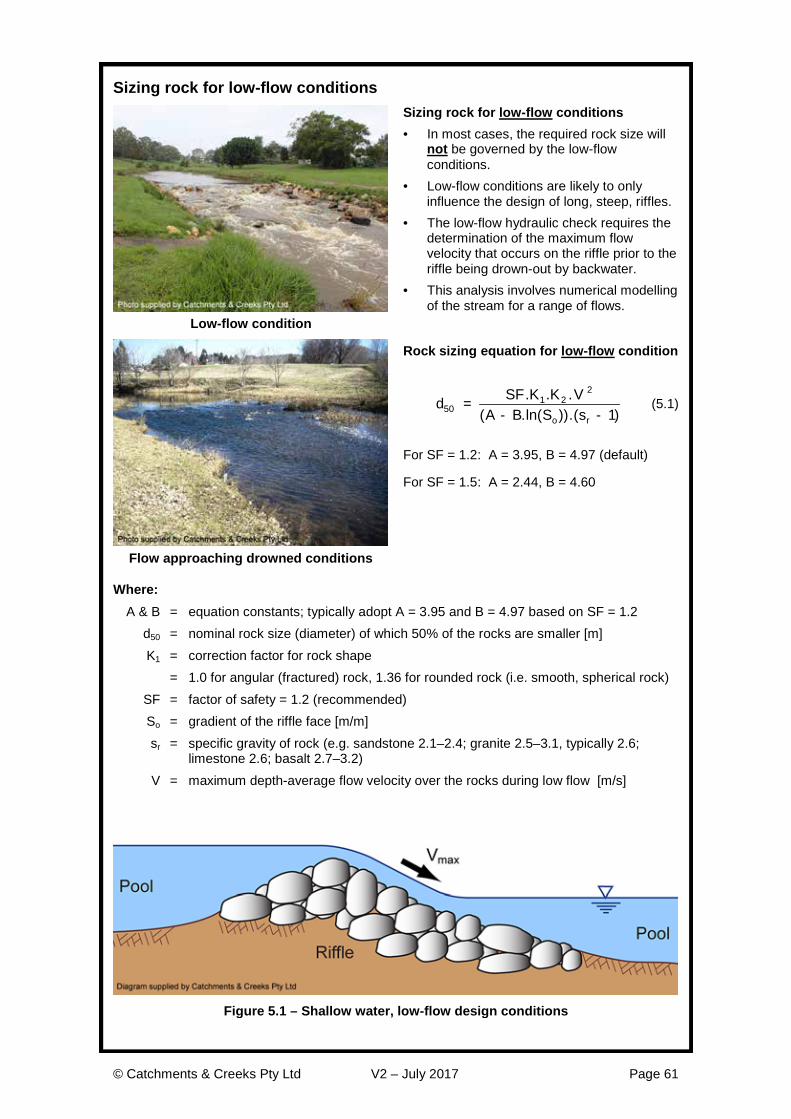
© Catchments & Creeks Pty Ltd V2 – July 2017 Page 61
Sizing rock for low-flow conditions
Sizing rock for low-flow conditions · In most cases, the required rock size will
not be governed by the low-flow conditions.
· Low-flow conditions are likely to only influence the design of long, steep, riffles.
· The low-flow hydraulic check requires the determination of the maximum flow velocity that occurs on the riffle prior to the riffle being drown-out by backwater.
· This analysis involves numerical modelling of the stream for a range of flows.
Low-flow condition
Rock sizing equation for low-flow condition
d SF K K VA B S so r
501 2
2
1=
- -. . .
( .ln( )).( ) (5.1)
For SF = 1.2: A = 3.95, B = 4.97 (default)
For SF = 1.5: A = 2.44, B = 4.60
Flow approaching drowned conditions
Where: A & B = equation constants; typically adopt A = 3.95 and B = 4.97 based on SF = 1.2 d50 = nominal rock size (diameter) of which 50% of the rocks are smaller [m] K1 = correction factor for rock shape = 1.0 for angular (fractured) rock, 1.36 for rounded rock (i.e. smooth, spherical rock) SF = factor of safety = 1.2 (recommended) So = gradient of the riffle face [m/m] sr = specific gravity of rock (e.g. sandstone 2.1–2.4; granite 2.5–3.1, typically 2.6;
limestone 2.6; basalt 2.7–3.2) V = maximum depth-average flow velocity over the rocks during low flow [m/s]
Figure 5.1 – Shallow water, low-flow design conditions
© Catchments & Creeks Pty Ltd V2 – July 2017 Page 62
Sizing rock for high-flow conditions The ‘high-flow’ hydraulic check requires the nomination of the maximum stream flow during which the riffle rock is required to be stable, e.g. the 1 in 10 year (10% AEP) or 1 in 50 year (2% AEP) discharge. This flow condition is then modelled to determine the maximum depth-average flow velocity passing over the riffle.
It is important that the calculated ‘depth-average velocity’ is representative of the actual flow velocities above the riffle, not the flow velocity averaged across the full cross-section.
Minimum, mean rock size for these high flow conditions may be determined from equation 5.2.
d K Vg K sr
501
2
22 1=
-.
. . ( ) (5.2)
where: K = equation constant based on flow conditions = 1.1 for low-turbulent deepwater flow or 0.86 for highly turbulent flow; otherwise,
refer to Table 1 for suggested vales of ‘K’ based on the flood gradient V = nominated design, deepwater, flow velocity over the rocks [m/s] g = acceleration due to gravity [m/s2]
Table 5.1 – Suggested values of ‘K’ for various flood gradients
Flood gradient (%) 1.0 2.0 3.0 4.0 5.0 6.0 8.0 10.0
K = 1.09 1.01 0.96 0.92 0.89 0.86 0.83 0.80
Flow conditions Low turbulence Ô Ô Ô Ô Ô Ô Ô Ô Highly turbulent (whitewater)
Specification of rock for constructed riffles In circumstances where the constructed riffle is required to simulate ‘natural’ bed conditions, and the riffle is located in a waterway that contains natural pool–riffle systems, then the rocks used in construction of the riffle should match the size distribution of the natural riffle systems. For constructed riffles that are required to be stable during major flood flows, then the following rock specifications should be considered.
Crushed rock is generally more stable than natural rounded rock; however, rounded rock has a more ‘natural’ appearance and is considered more fish friendly. A 36% increase in rock size is recommended for rounded rock (i.e. K1 = 1.36).
Broken concrete and building rubble should not be used.
The rock should be durable and resistant to weathering, and should be proportioned so that neither the breadth nor the thickness of a single rock is less than one-third its length.
The maximum rock size generally should not exceed twice the mean (d50) rock size.
Table 5.2 provides a suggested distribution rock sizes for constructed riffles.
Table 5.2 – Recommended distribution of rock size for constructed riffles
Rock size ratio Assumed distribution value d100/d50 2.0 d90/d50 1.8 d75/d50 1.5 d65/d50 1.3 d40/d50 0.65 d33/d50 0.50 d25/d50 0.45 d10/d50 0.20

© Catchments & Creeks Pty Ltd V2 – July 2017 Page 63
References ASCE 1992, Design and construction of urban stormwater management systems. ASCE Manuals and Reports of Engineering Practice No. 77, and Water Environment Federation Manual of Practice FD-20, American Society of Civil Engineers, New York.
Bohan, J.P., 1970, Erosion and riprap requirements at culvert and storm-drain outlets. Research Report H-70-2, U.S. Army Engineer Waterway Experiment Station, Vicksburg, Mississippi, USA
Bos, M.G., Reploge, J.A. and Clemmens, A.J. 1984, Flow measuring flumes for open channel systems, John Wiley & Sons, New York.
Isbash, S.V. 1936, Construction of dams by depositing rock in running water, Transactions, Second Congress on Large Dams, Washington, D.C. USA.
Orange County, 1989, Soil Erosion and Sediment Control Manual. Orange County Planning Department, Hillsborough, North Carolina, USA
Peterka, A.J. 1984, Hydraulic Design of stilling basins and bucket energy dissipators. USBR Engineering Monograph 25, U.S. Department of the interior, Bureau of Reclamation, Denver.
Witter, R.J. & Abt, S.R. 1990, The influence of uniformity on riprap stability. Proceedings of the 1990 National Conference – Hydraulic Engineering, San Diego, California, July-Aug 1990. Hydraulics Division of the American Society of Civil Engineers, New York, USA.

© Catchments & Creeks Pty Ltd V2 – July 2017 Page 64