version final 442 main south road,...
TRANSCRIPT

Denton Oval BU 0770-003 EQ2
Detailed Engineering Evaluation Quantitative Report
Version FINAL
442 Main South Road, Hornby

Denton Oval BU 0770-003 EQ2
Detailed Engineering Evaluation Quantitative Report
Version FINAL
442 Main South Road, Hornby
Christchurch City Council
Prepared By Jay Zeus B. Rivera
Reviewed By Stephen Lee
Date
07/03/13

iii
51/30596/04/
Detailed Engineering Evaluations Denton Oval
Contents
Quantitative Report Summary 1
1. Background 3
2. Compliance 4
2.1 Canterbury Earthquake Recovery Authority (CERA) 4
2.2 Building Act 4
2.3 Christchurch City Council Policy 6
2.4 Building Code 6
3. Earthquake Resistance Standards 7
4. Building Description 9
4.1 General 9
4.2 Gravity Load Resisting System 15
4.3 Lateral Load Resisting System 15
5. Assessment 17
5.1 Site Inspection 17
5.2 Investigation & Opening Up Work 17
5.3 Analysis and Modelling Methodology 17
5.4 Calculations 19
6. Damage Assessment 20
6.1 Surrounding Buildings 20
6.2 Residual Displacements and General Observations 20
6.3 Ground Damage 20
7. Analysis 21
7.1 Seismic Parameters 21
7.2 Wind Parameters 21
7.3 Structural Ductility Factor 22
8. Geotechnical Consideration 23
8.1.1 Published Information on Ground Conditions 23
8.1.2 Seismicity 25
8.1.3 Field Investigations 26

iv
51/30596/04/
Detailed Engineering Evaluations Denton Oval
8.1.4 Ground Conditions Encountered 27
8.1.5 Interpretation of Ground Conditions 27
9. Results 28
9.1 %NBS 28
9.2 Lateral Seismic Drift 31
9.3 Discussion of Results 31
10. Conclusions 32
10.1 Building Capacity Assessment 32
11. Recommendations 33
12. Limitations 34
12.1 General 34
12.2 Geotechnical Limitations 34
13. References 36
Table Index
Table 1 %NBS compared to relative risk of failure 8
Table 2 ECan Bore Log Summary Table 23
Table 3 Summary of Active Known Faults 235
Table 4 Coordinates of Investigation Locations 26
Table 5 Summary of CPT-Inferred Lithology 27
Figure Index
Figure 1 NZSEE Risk Classifications Extracted from Table
2.2 of the NZSEE 2006 AISPBE 7
Figure 2 Aerial photograph of Denton Oval 10
Figure 3 Framing plan of the grandstand 11
Figure 4 Roof framing plan of the grandstand 12
Figure 5 Typical frame elevation 13
Figure 6 Masonry wall layout for Amenity Building 14
Figure 7 3D Mathematical Model of Denton Oval's
Grandstand in Etabs 18
Figure 8 Post February 2011 Earthquake Aerial
Photography 25
v
51/30596/04/
Detailed Engineering Evaluations Denton Oval
Appendices
A Geotechnical Investigation Reports and Analysis
B Photographs
C Existing Drawings
D CERA Report Forms

1
51/30596/04/
Detailed Engineering Evaluations Denton Oval
Quantitative Report Summary
Denton Oval
BU 0770-003 EQ2
Detailed Engineering Evaluation
Quantitative Report - SUMMARY
Version FINAL
442 Main South Road, Hornby
Background
This is a summary of the Quantitative report for the structures of the buildings at Denton Oval, and is
based in general on the Detailed Engineering Evaluation Procedure document (draft) issued by the
Structural Advisory Group on 19 July 2011 and visual inspections on 18th May 2012.
Building Description
The buildings at Denton Oval consist of a steel and reinforced concrete grandstand structure with a
one(1) storey unreinforced masonry amenity building beneath it and a two (2) storey masonry Hornby
Cycling Clubrooms building. The grandstand and the Hornby cycling clubroom building were separated
by a seismic gap. This report focusses on the assessment of the grandstand and the amenity building
only.
Building Capacity Assessment
For the purpose of seismic assessment, the grandstand and the amenity building have been analysed
separately. This is due to the lack of connection between the walls of the amenity building and the
concrete frame of the grandstand. The grandstand is composed of steel frame atop of the concrete
frame while the amenity building is composed mainly of unreinforced masonry block wall. The amenity
building is then classified into two blocks, Block A serves as an office and changing room for players and
officials while Block B is for Men’s and Women’s toilet.
The grandstand achieved a rating of 35% NBS while the amenity building scored 22% NBS. The rating
of the changing area is greatly affected by the unreinforced masonry block walls that support the
lightweight roof. The walls do not have sufficient strength to resist lateral loads that are transferred to it
by the roof. Therefore the building is considered “Earthquake Prone”.
However it should be noted that considering the size and location of the amenity building (the weakest
part of the building), it does not pose significant risk to the grandstand even if it collapses.
2
51/30596/04/
Detailed Engineering Evaluations Denton Oval
Key Damage Observed
Key damage observed:
Minor cracking in concrete masonry walls in the changing room areas of the amenity building.
Recommendations
GHD recommend that further work is undertaken in order to develop a strengthening and repair scheme.
This work should involve:
Developing a strengthening works scheme to increase the seismic capacity of the grandstand and
the amenity building to as near as practicable to 100% NBS, or at least 67% NBS.
The structure should remain unoccupied until such time that strengthening works are completed.

3
51/30596/04/
Detailed Engineering Evaluations Denton Oval
1. Background
GHD has been engaged by the Christchurch City Council (CCC) to undertake a detailed engineering
evaluation of Denton Oval.
This report is a Quantitative Assessment of the building structure, and is based in general on the
Detailed Engineering Evaluation Procedure document (draft) issued by the Structural Advisory Group on
19 July 2011.
A quantitative assessment involves analysis and checking of all structural members that forms part of
the structure that contributes in resisting of horizontal and vertical forces that are subjected to it.
Furthermore, it is also used to evaluate the existing conditions of the structure with respect to our
prevailing industry codes and standards.
The main purpose of this procedure is to assess how the structure will respond upon application of
external forces and to what extend will the damage may be with respect to its existing condition.
Evaluating the capacity of the structure versus the applied loads, we can determine the structure’s rating
in terms of percentage of New Building Standards (%NBS) as per NZSEE requirements.

4
51/30596/04/
Detailed Engineering Evaluations Denton Oval
2. Compliance
This section contains a brief summary of the requirements of the various statutes and authorities that
control activities in relation to buildings in Christchurch at present.
2.1 Canterbury Earthquake Recovery Authority (CERA)
CERA was established on 28 March 2011 to take control of the recovery of Christchurch using powers
established by the Canterbury Earthquake Recovery Act enacted on 18 April 2011. This act gives the
Chief Executive Officer of CERA wide powers in relation to building safety, demolition and repair. Two
relevant sections are:
Section 38 – Works
This section outlines a process in which the chief executive can give notice that a building is to be
demolished and if the owner does not carry out the demolition, the chief executive can commission the
demolition and recover the costs from the owner or by placing a charge on the owners’ land.
Section 51 – Requiring Structural Survey
This section enables the chief executive to require a building owner, insurer or mortgagee carry out a full
structural survey before the building is re-occupied.
CERA now requires a detailed engineering evaluation to be carried out for all buildings (other than those
exempt from the Earthquake Prone Building definition in the Building Act). The Detailed Engineering
Evaluation Procedure document (draft) issued by the Structural Advisory Group on 19 July 2011 has
been adopted by CERA for evaluations. This document sets out a methodology for both qualitative and
quantitative assessments.
The qualitative assessment is a desk-top and site inspection assessment. It is based on a thorough
visual inspection of the building coupled with a review of available documentation such as drawings and
specifications. The quantitative assessment involves analytical calculation of the buildings strength and
may require non-destructive or destructive material testing, geotechnical testing and intrusive
investigation.
Factors determining the extent of evaluation and strengthening level required will include:
The importance level and occupancy of the building
The placard status and amount of damage
The age and structural type of the building
Consideration of any critical structural weaknesses
The extent of any earthquake damage
2.2 Building Act
Several sections of the Building Act are relevant when considering structural requirements:
Section 112 – Alterations

5
51/30596/04/
Detailed Engineering Evaluations Denton Oval
This section requires that an existing building complies with the relevant sections of the Building Code to
at least the extent that it did prior to any alteration. This effectively means that a building cannot be
weakened as a result of an alteration (including partial demolition).
Section 115 – Change of Use
This section requires that the territorial authority (in this case Christchurch City Council (CCC)) be
satisfied that the building with a new use complies with the relevant sections of the Building Code ‘as
near as is reasonably practicable’. Regarding seismic capacity ‘as near as reasonably practicable’ has
previously been interpreted by CCC as achieving a minimum of 67% NBS however where practical
achieving 100% NBS is desirable. The New Zealand Society for Earthquake Engineering (NZSEE)
recommend a minimum of 67% NBS.
2.2.1 Section 121 – Dangerous Buildings
The definition of dangerous building in the Act was extended by the Canterbury Earthquake (Building
Act) Order 2010, and it now defines a building as dangerous if:
In the ordinary course of events (excluding the occurrence of an earthquake), the building is likely
to cause injury or death or damage to other property; or
In the event of fire, injury or death to any persons in the building or on other property is likely
because of fire hazard or the occupancy of the building; or
There is a risk that the building could collapse or otherwise cause injury or death as a result of
earthquake shaking that is less than a ‘moderate earthquake’ (refer to Section 122 below); or
There is a risk that that other property could collapse or otherwise cause injury or death; or
A territorial authority has not been able to undertake an inspection to determine whether the
building is dangerous.
Section 122 – Earthquake Prone Buildings
This section defines a building as earthquake prone if its ultimate capacity would be exceeded in a
‘moderate earthquake’ and it would be likely to collapse causing injury or death, or damage to other
property. A moderate earthquake is defined by the building regulations as one that would generate
ground shaking 33% of the shaking used to design an equivalent new building.
Section 124 – Powers of Territorial Authorities
This section gives the territorial authority the power to require strengthening work within specified
timeframes or to close and prevent occupancy to any building defined as dangerous or earthquake
prone.
Section 131 – Earthquake Prone Building Policy
This section requires the territorial authority to adopt a specific policy for earthquake prone, dangerous
and insanitary buildings.

6
51/30596/04/
Detailed Engineering Evaluations Denton Oval
2.3 Christchurch City Council Policy
Christchurch City Council adopted their Earthquake Prone, Dangerous and Insanitary Building Policy in
2006. This policy was amended immediately following the Darfield Earthquake of the 4th September
2010.
The 2010 amendment includes the following:
A process for identifying, categorising and prioritising Earthquake Prone Buildings, commencing on
1 July 2012;
A strengthening target level of 67% of a new building for buildings that are Earthquake Prone;
A timeframe of 15-30 years for Earthquake Prone Buildings to be strengthened; and,
Repair works for buildings damaged by earthquakes will be required to comply with the above.
The council has stated their willingness to consider retrofit proposals on a case by case basis,
considering the economic impact of such a retrofit.
We anticipate that any building with a capacity of less than 33% NBS (including consideration of critical
structural weaknesses) will need to be strengthened to a target of 67% NBS of new building standard as
recommended by the Policy.
If strengthening works are undertaken, a building consent will be required. A requirement of the consent
will require upgrade of the building to comply ‘as near as is reasonably practicable’ with:
The accessibility requirements of the Building Code.
The fire requirements of the Building Code. This is likely to require a fire report to be submitted with
the building consent application.
2.4 Building Code
The building code outlines performance standards for buildings and the Building Act requires that all
new buildings comply with this code. Compliance Documents published by The Department of Building
and Housing can be used to demonstrate compliance with the Building Code.
After the February Earthquake, on 19 May 2011, Compliance Document B1: Structure was amended to
include increased seismic design requirements for Canterbury as follows:
Hazard Factor increased from 0.22 to 0.3 (36% increase in the basic seismic design load)
Serviceability Return Period Factor increased from 0.25 to 0.33 (80% increase in the serviceability
design loads when combined with the Hazard Factor increase)
The increase in the above factors has resulted in a reduction in the level of compliance of an existing
building relative to a new building despite the capacity of the existing building not changing.

7
51/30596/04/
Detailed Engineering Evaluations Denton Oval
3. Earthquake Resistance Standards
For this assessment, the building’s earthquake resistance is compared with the current New Zealand
Building Code requirements for a new building constructed on the site. This is expressed as a
percentage of new building standard (%NBS). The new building standard load requirements have been
determined in accordance with the current earthquake loading standard (NZS 1170.5:2004 Structural
design actions - Earthquake actions - New Zealand).
The likely capacity of this building has been derived in accordance with the New Zealand Society for
Earthquake Engineering (NZSEE) guidelines ‘Assessment and Improvement of the Structural
Performance of Buildings in Earthquakes’ (AISPBE), 2006. These guidelines provide an Initial
Evaluation Procedure that assesses a buildings capacity based on a comparison of loading codes from
when the building was designed and currently. It is a quick high-level procedure that can be used when
undertaking a Qualitative analysis of a building. The guidelines also provide guidance on calculating a
modified Ultimate Limit State capacity of the building which is much more accurate and can be used
when undertaking a Quantitative analysis.
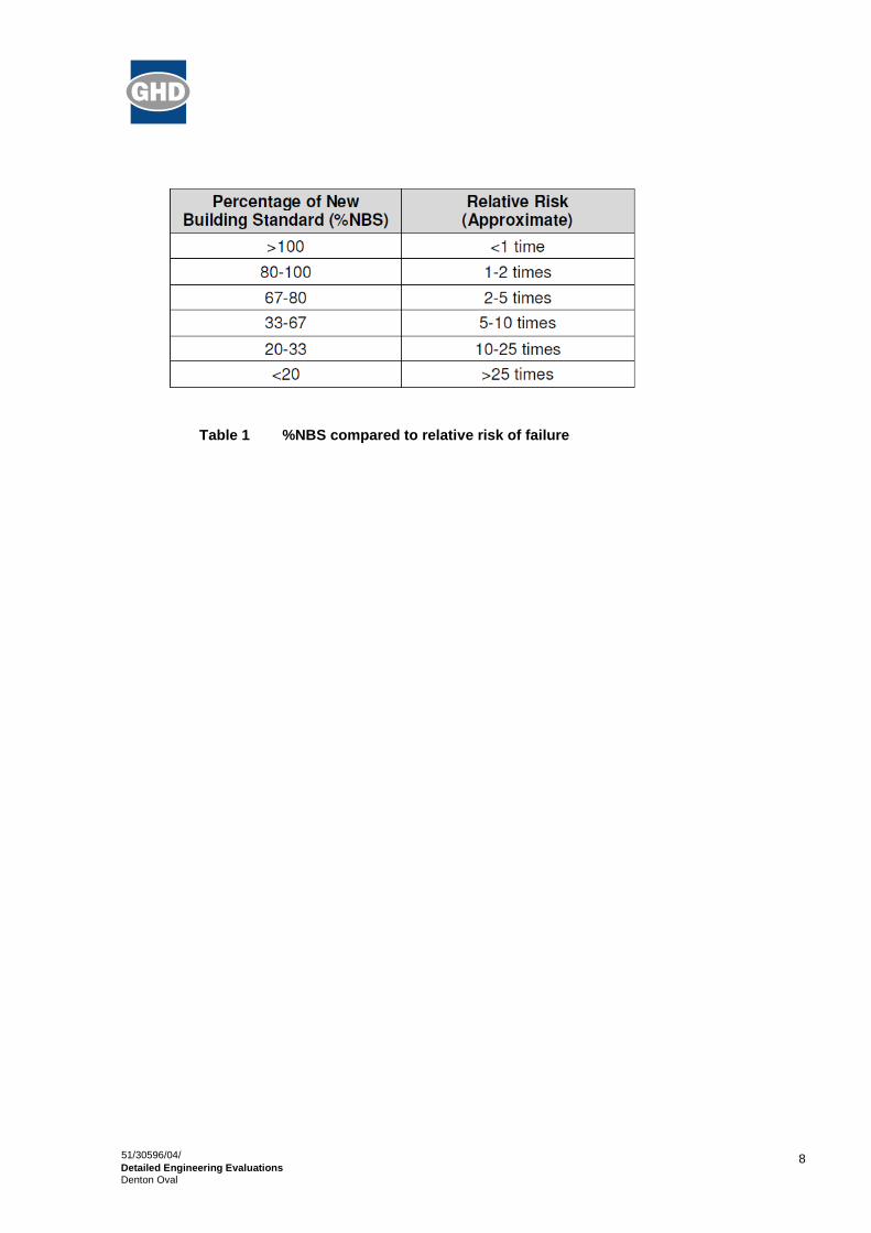
The New Zealand Society for Earthquake Engineering has proposed a way for classifying earthquake
risk for existing buildings in terms of %NBS and this is shown in Figure 1 below.
Figure 1 NZSEE Risk Classifications Extracted from Table 2.2 of the NZSEE 2006 AISPBE
Table 1 compares the percentage NBS to the relative risk of the building failing in a seismic event with a
10% risk of exceedance in 50 years (i.e. 0.2% in the next year). It is noted that the current seismic risk in
Christchurch results in a 6% risk of exceedance in the next year.
8
51/30596/04/
Detailed Engineering Evaluations Denton Oval
Table 1 %NBS compared to relative risk of failure

9
51/30596/04/
Detailed Engineering Evaluations Denton Oval
4. Building Description
4.1 General
Denton Oval is located in 442 Main South Road, Hornby Christchurch and can be accessed thru
Chalmers Road. The site is consisting of a 400 m length concrete velodrome, a rugby playing field, a
reinforced concrete grandstand with an amenity building underneath and a two storey concrete masonry
Hornby cycling clubrooms building. The stadium was built in 1974 for the Commonwealth games. In
1990, the Hornby cycling clubrooms were constructed at the right side of the grandstand. A seismic gap
was created in order to have a separation between the existing grandstand and the new Hornby cycling
clubrooms building.
The main structure is composed of a grandstand and the amenity building. For the purpose of analysis,
the two (2) are separately assessed and checked.
The grandstand is divided into two major components which are the steel frame and the concrete frame
assembly. The grandstand has a base dimension of 11.80 m x 41.40 m and a height of approximately
9.30 m from ground to roof apex. It has a capacity of approximately 2000 people and offers a full view of
the whole velodrome and the playing field.
The steel frame assembly serves as the support for the roof of the structure. The roof consists of
lightweight metal roof sheeting on light gauge metal purlins supported by a series of 250UB rafters
spanning from the back of the structure up to the front. These rafters are then supported by a 460UB
longitudinal beam at the front and a series of 250UB columns at the back of the structure. The 460UB
longitudinal beam is supported by 4-150x150x6 SHS columns spaced at every 13.80 m. Three (3) layers
of 125x75x6 RHS horizontal girt beams are seen at the back of the structure in between 250UB
columns. These girt beams are equally spaced up the height of the column and give lateral support to
the columns and also supports the cladding for the grandstand. All the columns, both the 250UB and the
150x150x6 SHS, are pinned connected to the concrete frame structure below it.
The concrete frame assembly serves as the support for the steel frame and the bleacher seats. It is
composed of a series of 450 mm x 450 mm R.C. columns supporting the 300 mm x 1000 mm pre-
stressed concrete raking beams. These raking beams are inclined from the ground by 27°. A series of
225 mm x 550 mm longitudinal beams laterally support the columns in the longitudinal direction. Double
T precast concrete units serve as the flooring for the grandstand and are supported by the raking
beams. The concrete columns sit on reinforced concrete pad footings that are tied together by R.C.
footing tie beams.
The amenity building is located underneath the grandstand. It is divided into two (2) blocks, namely
Block A and B. Block A has a base dimension of 9.00 m x 22.90 m and Block B has 5.40 m x 13.80 m.
Roof height for both Block A and B is 3.45 m from finished floor level. Block A serves as a changing
room and office while Block B is the toilet block. A portion of Block A is under the grandstand while the
rest is extended outward. Block B has its back wall at the face of the grandstand columns and extends
outward from the grandstand. The roof is made of lightweight metal sheet on 75 mm x 50 mm timber
purlins supported by 250 mm x 50 mm timber rafters. The walls are made up of 190 mm thick concrete
masonry block. A 100 mm thick concrete ground slab serves as the floor for both Blocks A and B. The
masonry block walls are only reinforced horizontally in bond beams at the top of the walls and vertically

10
51/30596/04/
Detailed Engineering Evaluations Denton Oval
at corners and edges of openings. The masonry block walls are just butted against the grandstand
columns without any structural connection. The block walls sit on reinforced concrete strip footings.
Refer to Figure 3 to 6 for steel, concrete and masonry plans and a typical frame elevation of the
structure.
Figure 2 Aerial photograph of Denton Oval

11
51/30596/04/
Detailed Engineering Evaluations
Denton Oval
Note:
B1 – 250mm x 550mm R.C. Beam C1 – 450mm x 450mm R.C. Column
B2 – 250mm x 550mm R.C. Beam SC1 – 150x150x6 SHS
PB1 – 300mm x 1000mm Pre-stress Concrete Beam SC2 – 250UB
Figure 3 Framing plan of the grandstand

12
51/30596/04/
Detailed Engineering Evaluations
Denton Oval
Note:
SB1 – 460UB
SB2(a-c) – 125x75x6 RHS
R1 – 250UB
Figure 4 Roof framing plan of the grandstand

13
51/30596/04/
Detailed Engineering Evaluations
Denton Oval
Note:
FTB1 – 300mm x 300mm R.C. Beam
Figure 5 Typical frame elevation

14
51/30596/04/
Detailed Engineering Evaluations
Denton Oval
Figure 6 Masonry wall layout for Amenity Building

15
51/30596/04/
Detailed Engineering Evaluations Denton Oval
4.2 Gravity Load Resisting System
4.2.1 Grandstand
The gravity loads for this structure are resisted by the steel frame and concrete frame system.
The roof structure of the grandstand consists of lightweight metal roofing on light gauge metal purlins
supported by a series of 250UB steel rafters. These steel rafters are supported by a 460UB longitudinal
steel beam along Gridline B and series of 250UB steel columns along Gridline D. The longitudinal steel
beam is then supported by 4-150x150x6SHS steel columns. These SHS columns are located along
Gridline 1, 4, 7 and 10. Then this steel frame transfer the gravity loads to the pre-stressed concrete
beam in which forms part of the concrete frame structure below.
The floor of the grandstand is composed of precast double tee units which are bolted and grouted to the
pre-stressed concrete raking beams. These precast double tee units support the wood benches for the
spectators. The raking beams then transferred the gravity forces to the R.C. columns along Gridline A
and C. These columns then transfer the gravity load to the foundations.
4.2.2 Amenity Building
The gravity loads in the amenity building for both Block A and B are resisted by the unreinforced
masonry walls. These gravity loads are transferred by the roof consisting of lightweight metal sheeting
on timber purlins supported by timber rafters to the unreinforced concrete masonry walls.
4.3 Lateral Load Resisting System
4.3.1 Grandstand
Lateral loads acting on the structure are resisted by the steel frame and concrete frame system.
The steel frame resists the lateral load for the upper portion of the grandstand. The roof cladding on
steel purlins acts as a diaphragm that transfers lateral load to the steel rafters that are supported by
steel columns. Lateral loads in longitudinal direction along Gridline D are resisted by series of 250UB
columns and RHS girt beams while on Gridline B, the 4-SHS columns and the 460UB beam act together
to provide a frame. For the transverse direction, steel frames consisting of a steel rafter and columns
resist lateral loads.
The concrete frame resists the lateral load for the lower part of the structure. With the help of the precast
concrete double tee units, which acts as diaphragms and as flooring as well for the grandstand, lateral
loads are transferred to the pre-stressed raking beams. Lateral loads in longitudinal direction are
resisted by reinforced concrete frame consisting of concrete columns and beams. Lateral loads in the
transverse direction are resisted by the combination of reinforced concrete columns and pre-stressed
concrete raking beams.
4.3.2 Amenity Building
In the changing room areas, lateral loads are resisted by concrete masonry walls in both the long and
short directions of the building.

16
51/30596/04/
Detailed Engineering Evaluations Denton Oval
The lateral loads in the amenity building are resisted by the unreinforced masonry walls. The lightweight
roof acts as a diaphragm and transfers lateral loads to the walls in plane. Also, the timber rafters act as
out-of-plane braces for these walls.

17
51/30596/04/
Detailed Engineering Evaluations Denton Oval
5. Assessment
5.1 Site Inspection
An inspection of the building was undertaken on the 18th of January 2012. Both the interior and exterior
of the building were inspected. The building was observed to have a green placard in place. The main
structural components of the building were all able to be viewed due to the exposed nature of the
structure. The underside of the grandstand is open and the concrete masonry changing rooms and the
two storey addition are unlined. No inspection of the foundations of the structure was able to be
undertaken.
The inspection consisted of observing the building to determine the structural systems and likely
behaviour of the building during an earthquake. The site was assessed for damage, including observing
the ground conditions, checking for damage in areas where damage would be expected for the structure
and noting damage observed throughout the building in both structural and non-structural elements.
5.2 Investigation & Opening Up Work
Further inspections were carried out on the 17th and 18
th of May 2012. The work included drafting of an
as-built plan of the structure because there are no available drawings/plans, taking of measurements
and dimensions of the structure as well as the key structural elements (i.e. columns, beams and walls).
Reinforcement scanning using a Hilti PS200 Ferroscan was also performed. A series of photographs of
key structural elements and connections were also taken.
5.3 Analysis and Modelling Methodology
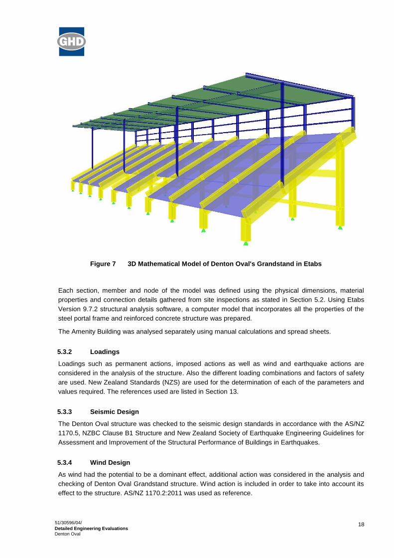
5.3.1 Mathematical Modelling
The three-dimensional frame modelling of the Denton Oval Grandstand structure was performed to
realistically simulate the effects of the applied loads on the structure under different conditions such as
normal operation, wind, earthquake and combinations thereof.
This modelling approach determines the adequacy of members or sections for the structure under
various loading conditions.
18
51/30596/04/
Detailed Engineering Evaluations Denton Oval
Figure 7 3D Mathematical Model of Denton Oval's Grandstand in Etabs
Each section, member and node of the model was defined using the physical dimensions, material
properties and connection details gathered from site inspections as stated in Section 5.2. Using Etabs
Version 9.7.2 structural analysis software, a computer model that incorporates all the properties of the
steel portal frame and reinforced concrete structure was prepared.
The Amenity Building was analysed separately using manual calculations and spread sheets.
5.3.2 Loadings
Loadings such as permanent actions, imposed actions as well as wind and earthquake actions are
considered in the analysis of the structure. Also the different loading combinations and factors of safety
are used. New Zealand Standards (NZS) are used for the determination of each of the parameters and
values required. The references used are listed in Section 13.
5.3.3 Seismic Design
The Denton Oval structure was checked to the seismic design standards in accordance with the AS/NZ
1170.5, NZBC Clause B1 Structure and New Zealand Society of Earthquake Engineering Guidelines for
Assessment and Improvement of the Structural Performance of Buildings in Earthquakes.
5.3.4 Wind Design
As wind had the potential to be a dominant effect, additional action was considered in the analysis and
checking of Denton Oval Grandstand structure. Wind action is included in order to take into account its
effect to the structure. AS/NZ 1170.2:2011 was used as reference.
19
51/30596/04/
Detailed Engineering Evaluations Denton Oval
5.4 Calculations
5.4.1 Determination of %NBS
After analysing the structure with the use of the mathematical model and spread sheets, all the structural
elements that form part for the structure were checked and individual demand capacity ratios were
computed. From there the %NBS of each element was determined.
20
51/30596/04/
Detailed Engineering Evaluations Denton Oval
6. Damage Assessment
6.1 Surrounding Buildings
No damage to surrounding buildings was observed during our inspection of the site.
6.2 Residual Displacements and General Observations
No residual displacements of the structure were noticed during our inspection of the building.
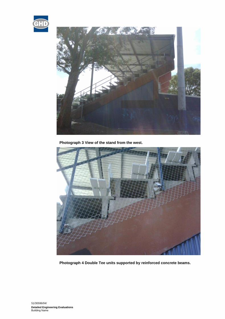
Minor cracking was noted in the concrete masonry partition wall that was built around one of the beams
supporting the stand seating as can be seen in Photograph 6.
Minor cracking was also noted in a number of the concrete masonry walls of the changing room areas.
These cracks have typically occurred around the doorways and in the corners of the rooms as can be
seen in Photograph 7.
6.3 Ground Damage
No ground damage was observed during our inspection of the site.

21
51/30596/04/
Detailed Engineering Evaluations Denton Oval
7. Analysis
7.1 Seismic Parameters
The seismic design parameters based on current design requirements from NZS1170.5:2002, NZS
3604:2011 and the NZBC clause B1 for this building are:
Location : Christchurch
Importance Level : 3
Site Classification : D
Seismic Zone Factor : 0.30
(Table 3.3, NZS 1170.5:2004)
Annual Probability of Exceedance : 1/1000 (ULS)
(Table 3.3, NZS 1170.0:2002)
Annual Probability of Exceedance : 1/25 (SLS)
(Table 3.3, NZS 1170.0:2002)
Return Period Factor (Ru) : 1.30 (ULS)
(Table 3.5, NZS 1170.5:2004)
Return Period Factor (Ru) : 0.33 (SLS)
(Table 3.5, NZS 1170.5:2004)
Ductility Factor,
Concrete Structure, (µc) : 1.25
Steel Structure, (µs) : 2.00
Masonry Wall, (µw) : 1.25
Performance Factor (Sp) : 0.925
Gravitational Constant (g) : 9.81 m/sec^2
Liquefaction Potential : Low
7.2 Wind Parameters
The wind design parameters based on current design requirements from NZS1170.2:2011 are:
Location : Christchurch
Importance Level : 3
Terrain Category Definition : Category 2
Region Classification : A7
Annual Probability of Exceedance : 1/1000 (ULS)

22
51/30596/04/
Detailed Engineering Evaluations Denton Oval
(Table 3.3, NZS 1170.0:2002)
Annual Probability of Exceedance : 1/25 (SLS)
(Table 3.3, NZS 1170.0:2002)
Wind Direction Multiplier (Md) : 1.00
Shielding Multiplier (Ms) : 1.00
Topographic Multiplier (Mt) : 1.00
Density of Air : 1.20 kg/m^3
7.3 Structural Ductility Factor
A structural ductility factor of 1.25 has been assumed for the reinforced concrete frame while 2.00 for the
steel frame. With this, a structural ductility factor of 1.25 was adopted for the whole structure because
the frames are connected to each other.
For the unreinforced masonry wall, a structural ductility factor of 1.25 has been assumed.

23
51/30596/04/
Detailed Engineering Evaluations Denton Oval
8. Geotechnical Consideration
The site is situated within a recreational reserve, within the suburb of Hornby in western Christchurch. It
is relatively flat at approximately 30m above mean sea level. It is approximately 2.5km west of the
Heathcote River, and 15km west of the coast (Pegasus Bay) at New Brighton.
The park is located between the Main South Railway line to the north and Main South Road (SH1) to the
south. It is bound to the east by commercial properties and west by residential properties. The property
is owned and maintained by the Christchurch City Council.
8.1.1 Published Information on Ground Conditions
8.1.1.1 Published Geology
The geological map of the area1 indicates that the site is underlain by:
Holocene alluvial soils of the Yaldhurst Member, sub-group of the Springston Formation,
which contains alluvial gravel, sand and silt of historic river flood channels.
8.1.1.2 Environment Canterbury Logs
Information from Environment Canterbury (ECan) indicates eight boreholes are located within a 200m
radius of the site. Of these boreholes, six of them had lithographic logs of which four are considered for
this report. The site geology described in these logs shows the area is predominantly sandy gravels with
varying amounts of silt and clay.
Table 2 ECan Bore Log Summary Table
Bore Name Depth (m bgl) Log Summary
M35/1865
(110m SE of site)
0 – 1
1 – 21
21 – 49
49 – 52
52 – 79
79 – 86
86 – 88
88 – 94
94 – 102
Hardfill
Fine to coarse GRAVEL and SAND
Medium dense to dense GRAVEL, with some sand and clay
Dense GRAVEL, with sand and clay
Fine to medium GRAVEL, with traces of clay
Sandy medium GRAVEL
PEAT
Dense GRAVEL, and stiff CLAY
Dense Sandy GRAVEL, with some yellow clay
M35/3546 0 – 0.3
0.3 – 3.9
Filling Material
SILT
1 Brown, L. J. and Weeber J.H. 1992: Geology of the Christchurch Urban Area. Institute of Geological and Nuclear Sciences 1:25,000 Geological Map 1. Lower Hutt. Institute of Geological and Nuclear Sciences Limited.

24
51/30596/04/
Detailed Engineering Evaluations Denton Oval
Bore Name Depth (m bgl) Log Summary
3.9 – 40.5
40.5 – 49.5
49.5 – 52
52 – 95.8
Sandy GRAVEL, with some clay
CLAY, with some gravel and peat
Dense GRAVEL, with some clay
Layers of CLAY, SAND and GRAVEL
M35/7739 0 – 6
6 – 23.5
23.5 – 29.5
Gravelly SAND
Sandy GRAVEL, with traces of silt and clay
Sandy GRAVEL
M35/7743 0 – 1
1 – 9
9 – 10.8
10.8 – 12.5
12.5 – 20.7
Clayey GRAVEL
Sandy GRAVEL, with some clay and silt
Sandy GRAVEL
Slightly clayey, fine SAND
Clayey GRAVEL and sandy GRAVEL
It should be noted the quality of soil logging descriptions included on the boreholes is unknown and were
likely written by the well driller and not a geotechnical professional or to a recognised geotechnical
standard. In addition strength data is not recorded.
8.1.1.3 EQC Geotechnical Investigations
The Earthquake Commission has not undertaken geotechnical testing in the area of the site.
8.1.1.4 Land Zoning
Canterbury Earthquake Recovery Authority (CERA) has zoned the site as Green, indicating repair and
rebuild may take place
CERA has published areas showing the Green Zone Technical Category in relation to the risk of future
liquefaction and how these areas are expected to perform in future earthquakes.
The site is classified as “not applicable”. This indicates that it is a non-residential properties in an urban
area that has not been given a Technical Category. However, nearby land has been classified as
Technical category 1 (TC1) which means that liquefaction is unlikely in a future earthquake event.
8.1.1.5 Post February Aerial Photography
Aerial photography taken following the 22 February 2011 earthquake (Figure 8) shows no signs of
liquefaction outside the building footprint or adjacent to the site.

25
51/30596/04/
Detailed Engineering Evaluations Denton Oval
Figure 8 Post February 2011 Earthquake Aerial Photography2
8.1.1.6 Summary of Ground Conditions from desk study
From the ECan borehole information the ground conditions on Main South Road comprise multiple strata
of gravel, sandy gravel and sand, with varying amounts of silt and clay.
8.1.2 Seismicity
8.1.2.1 Nearby Faults
There are many faults in the Christchurch region, however only those considered most likely to have an
adverse effect on the site are detailed below.
Table 3 Summary of Known Active Faults3,4
Known Active Fault Distance from Site (km)
Max Likely Magnitude
Avg Recurrence Interval
Alpine Fault 120 NW 8.3 ~300 years
Greendale (2010) Fault 13 W 7.1 ~15,000 years
2 Aerial Photography Supplied by Koordinates sourced from http://koordinates.com/layer/3185-christchurch-post-earthquake-aerial-
photos-24-feb-2011/
3 Stirling, M.W, McVerry, G.H, and Berryman K.R. (2002); “A New Seismic Hazard Model for New Zealand”, Bulletin of the
Seismological Society of America, Vol. 92 No. 5, pp 1878-1903, June 2002.
4 GNS Active Faults Database http://maps.gns.cri.nz/website/af/viewer

26
51/30596/04/
Detailed Engineering Evaluations Denton Oval
Known Active Fault Distance from Site (km)
Max Likely Magnitude
Avg Recurrence Interval
Hope Fault 100 N 7.2~7.5 120~200 years
Kelly Fault 100 NW 7.2 ~150 years
Porters Pass Fault 54 NW 7.0 ~1100 years
Recent earthquakes since 4 September 2010 have identified the presence of a previously unmapped
fault system underneath the Canterbury Plains including, Christchurch City and the Port Hills. Research
and published information on this system is in development and not generally available and average
recurrence intervals are yet to be estimated.
8.1.2.2 Ground Shaking Hazard
New Zealand Standard NZS 1170.5:2004 now quantifies the Seismic Hazard factor for Christchurch as
0.30, being in a moderate to high earthquake zone. This value has been provisionally upgraded recently
(from 0.22) to reflect the seismicity hazard observed in the earthquakes since 4 September 2010.
The recent seismic activity in Canterbury has produced earthquakes of Magnitude-7.1 (Sept., Darfield),
6.3 (Feb., and June, Christchurch) with peak ground accelerations (PGA) up to twice the acceleration
due to gravity (2g) in some parts of the city. This has resulted in widespread liquefaction throughout
Christchurch.
8.1.3 Field Investigations
In order to further understand the ground conditions at the site, intrusive testing comprising one
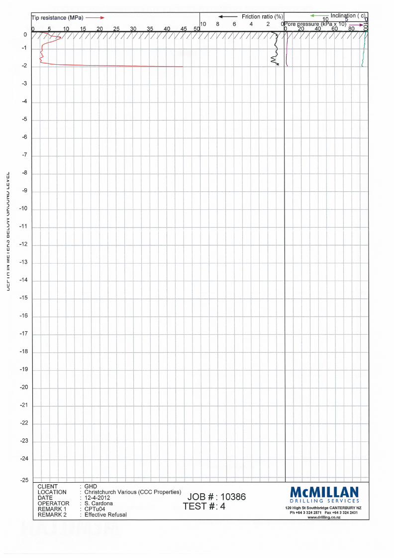
piezocone CPT investigation was conducted at the site on 12 April 2012.
The location of the test is tabulated in Table 4.
Table 4 Coordinates of Investigation Locations
Investigation Depth (m bgl) Easting (NZMG) Northing (NZMG)
CPT 001 2.0 2471263 5740467
The CPT investigation was undertaken by McMillan Drilling Service on 12 April 2012, typically to a target
depth of 20m below ground level. However, refusal was reached at depth of 2.0m due to the presence of
dense gravels. Please refer to the attached CPT results for detail (Appendix A).
Interpretation of output graphs5 from the investigation showing Cone Tip Resistance (qc), Friction Ratio
(Fr), Inferred Lithology and Inferred Liquefaction Potential are presented in Table 5.
5 McMillans Drilling CPT data plots, Appendix A.

27
51/30596/04/
Detailed Engineering Evaluations Denton Oval
8.1.4 Ground Conditions Encountered
8.1.4.1 Summary of CPT-Inferred Lithology
Table 5 Summary of CPT-Inferred Lithology
Depth (m) Lithology 1
Cone Tip Resistance
qc (MPa)
Friction Ratio
Fr (%)
0 – 2.0 Surface soil ~5 ~1
>2.0 Gravel > 20 ~0
8.1.5 Interpretation of Ground Conditions
8.1.5.1 Liquefaction Assessment
Based on an overall assessment of the following, the site is considered unlikely to be susceptible to
liquefaction confirming the CERA TC1 classification.
The identified ground conditions confirmed by CPT;
The minimal damage to ground (and building) caused by the Canterbury earthquake
sequence evidenced by aerial and visual inspection.
8.1.5.2 Slope Failure and/or Rockfall Potential
The site is located within Hornby, a flat suburb in western Christchurch. Global slope instability risk is
considered negligible. However, any localised retaining structures and/or embankments should be
further investigated to determine the site-specific slope instability potential.
8.1.5.3 Foundation Recommendations
Following the guidance provided by the Department of Housing and building6
(DBH) in Section 4 for
repairing of foundations for TC1 dwellings, the following geotechnical recommendations are provided.
A site subsoil class of D, Deep or Soft Soil, should be adopted for this sites (in accordance
with NZS 1170.5:2004)
An allowable bearing capacity of 100kPa can be used for any replacement shallow
foundations required.
If a re-build is deemed necessary a shallow investigation specific to the new building footprint
should be undertaken. Shallow ground improvement is not required.

28
51/30596/04/
Detailed Engineering Evaluations Denton Oval
9. Results
The following are the results of the structural analysis for Denton Oval structure.
9.1 %NBS
Our analysis showed that seismic effects were most critical.
9.1.1 Grandstand
Steel Rafters
Ten (10) steel rafters rated below 67% NBS and they are highlighted in red in the figure below. The
lowest rating achieved is 35% NBS.
Steel Beams
All steel beams have a rating of greater than 67% NBS.
29
51/30596/04/
Detailed Engineering Evaluations Denton Oval
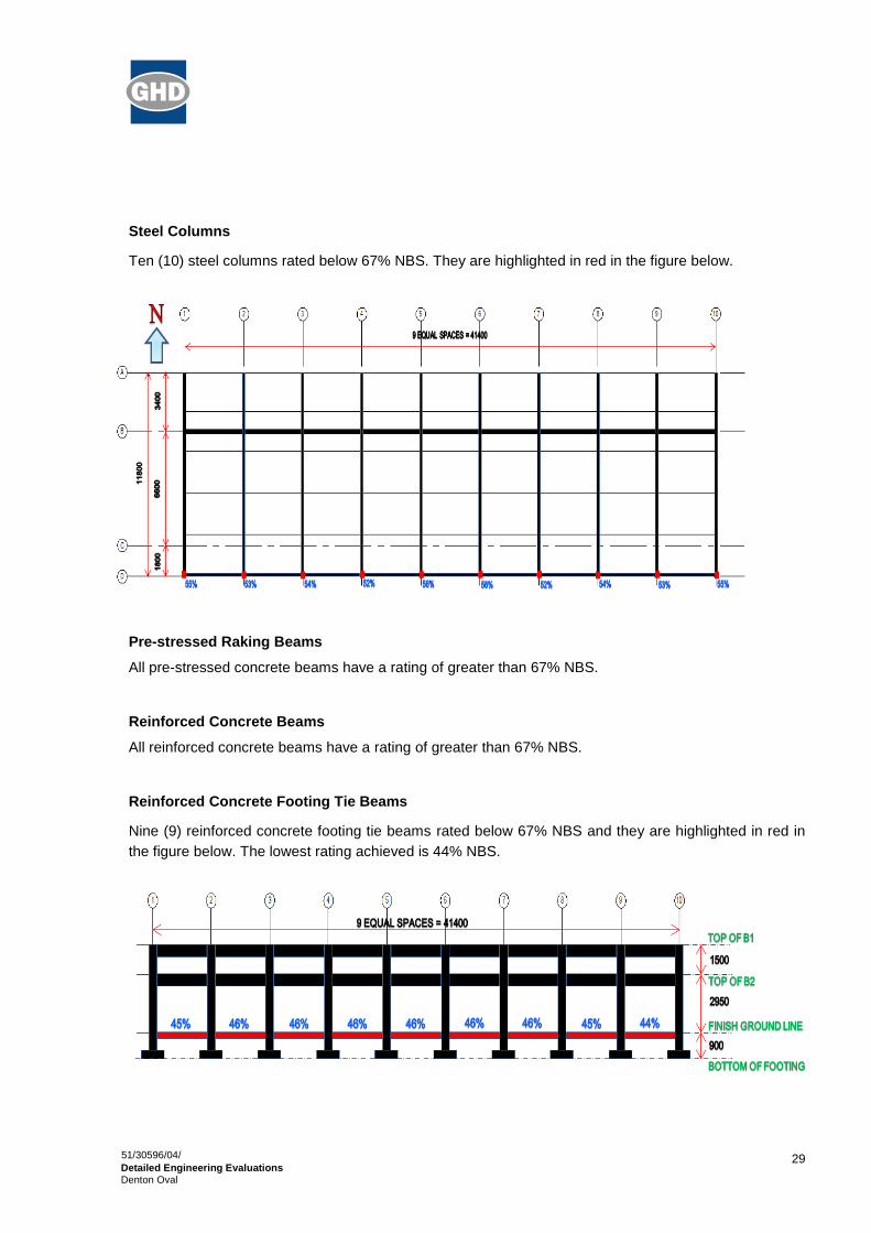
Steel Columns
Ten (10) steel columns rated below 67% NBS. They are highlighted in red in the figure below.
Pre-stressed Raking Beams
All pre-stressed concrete beams have a rating of greater than 67% NBS.
Reinforced Concrete Beams
All reinforced concrete beams have a rating of greater than 67% NBS.
Reinforced Concrete Footing Tie Beams
Nine (9) reinforced concrete footing tie beams rated below 67% NBS and they are highlighted in red in
the figure below. The lowest rating achieved is 44% NBS.

30
51/30596/04/
Detailed Engineering Evaluations Denton Oval
Reinforced Concrete Columns
Ten (10) reinforced concrete columns rated below 67% NBS and they are highlighted in red in the figure
below. The lowest rating achieved is 52% NBS.
9.1.2 Amenity Building
Unreinforced Masonry Walls
Block A - Three (3) unreinforced masonry wall rated below 34% NBS and twenty two (22) unreinforced
masonry walls rated below 67% NBS. They are highlighted in red in the figure below.
Block B - Five (5) unreinforced masonry wall rated below 34% NBS and two (2) unreinforced masonry
walls rated below 67% NBS. They are highlighted in red in the figure below.

31
51/30596/04/
Detailed Engineering Evaluations Denton Oval
Reinforced Concrete Masonry Bond Beam
All reinforced concrete masonry bond beams have a rating of greater than 67% NBS.
9.1.3 Hornby Cycling Clubrooms
This building was assessed at 65% NBS based on a qualitative assessment completed in February 2012. No further assessment has been carried out.
9.2 Lateral Seismic Drift
The computed drift of the Denton Oval is 34 mm and 60 mm in the longitudinal and transverse direction
respectively.
The existing seismic gap between the grandstand and the two (2) storey masonry horny cycling club
building is approximately 100 mm in the longitudinal direction.
9.3 Discussion of Results
Based on the quantitative analysis done for the structure, it is found that the lowest rating achieved is
22% NBS. This rating comes from the unreinforced masonry wall in Block B of Amenity building. This is
to be expected since there is virtually no vertical or horizontal reinforcement present in the walls. It
would appear that the amenity building, considering the materials used and the prevailing codes and
standards at the time it was constructed, serves only to carry gravity loads and not lateral loads.
The grandstand as a structure, considered in isolation, achieved a ratings of 35% NBS.

32
51/30596/04/
Detailed Engineering Evaluations Denton Oval
10. Conclusions
10.1 Building Capacity Assessment
Based on the quantitative assessment of the structure, it is found that the overall seismic capacity is
22% NBS. This is a result of the unreinforced masonry walls in Block B of the Amenity building under the
grandstand. Therefore, the building is classified as an ‘Earthquake Prone’ building.

33
51/30596/04/
Detailed Engineering Evaluations Denton Oval
11. Recommendations
GHD recommend that further work is undertaken in order to develop a strengthening and repair scheme.
This work should involve:
Developing a strengthening works scheme to increase the seismic capacity of the Denton Oval
grandstand and the amenity building to as near as practicable to 100% NBS, or at least 67% NBS.
This will need to consider compliance with accessibility and fire requirements.
The structure should remain unoccupied until such time that strengthening works are completed.

34
51/30596/04/
Detailed Engineering Evaluations Denton Oval
12. Limitations
12.1 General
This report has been prepared subject to the following limitations:
The only available drawing is for the amenity building with nothing for the grandstand. As a result,
the information contained in this report has been inferred from site inspection done on the
structure.
The Hornby cycling clubrooms building was not checked.
The foundations of the structure were not checked.
No level or verticality surveys have been undertaken.
No material testing has been undertaken.
It is noted that this report has been prepared at the request of Christchurch City Council and is intended
to be used for their purposes only. GHD accepts no responsibility for any other party or person who
relies on the information contained in this report.
12.2 Geotechnical Limitations
The data and advice provided herein relate only to the project and structures described herein and must
be reviewed by a competent geotechnical engineer before being used for any other purpose. GHD
Limited (GHD) accepts no responsibility for other use of the data by third parties.
Where drill hole or test pit logs, cone tests, laboratory tests, geophysical tests and similar work have
been performed and recorded by others under a separate commission, the data is included and used in
the form provided by others. The responsibility for the accuracy of such data remains with the issuing
authority, not with GHD.
The advice tendered in this report is based on information obtained from the desk study investigation
location test points and sample points. It is not warranted in respect to the conditions that may be
encountered across the site other than at these locations. It is emphasised that the actual characteristics
of the subsurface materials may vary significantly between adjacent test points, sample intervals and at
locations other than where observations, explorations and investigations have been made. Subsurface
conditions, including groundwater levels and contaminant concentrations can change in a limited time.
This should be borne in mind when assessing the data.
It should be noted that because of the inherent uncertainties in subsurface evaluations, changed or
unanticipated subsurface conditions may occur that could affect total project cost and/or execution. GHD
does not accept responsibility for the consequences of significant variances in the conditions and the
requirements for execution of the work.
The subsurface and surface earthworks, excavations and foundations should be examined by a suitably
qualified and experienced Engineer who shall judge whether the revealed conditions accord with both
the assumptions in this report and/or the design of the works. If they do not accord, the Engineer shall
modify advice in this report and/or design of the works to accord with the circumstances that are
revealed.

35
51/30596/04/
Detailed Engineering Evaluations Denton Oval
An understanding of the geotechnical site conditions depends on the integration of many pieces of
information, some regional, some site specific, some structure specific and some experienced based.
Hence this report should not be altered, amended or abbreviated, issued in part and issued incomplete
in any way without prior checking and approval by GHD. GHD accepts no responsibility for any
circumstances which arise from the issue of the report which have been modified in any way as outlined
in Section 8.

36
51/30596/04/
Detailed Engineering Evaluations Denton Oval
13. References
1. Detailed Engineering Evaluation Qualitative Report for Denton Oval, February 24, 2012, GHD Pty.
Ltd.
2. AS/NZS 1170.0:2002 Structural design actions, Part 0: General Principles, New Zealand Standards
3. AS/NZS 1170.0 Supplement 1:2002 Structural design actions - General principles - Commentary
4. AS/NZS 1170.1:2002 Structural design actions, Part 1: Permanent, imposed and other actions, New
Zealand Standards
5. AS/NZS 1170.1 Supplement 1:2002 Structural design actions – Permanent, imposed and other
actions - Commentary
6. AS/NZS 1170.2:2011 Structural design actions, Part 2: Wind actions, New Zealand Standards
7. AS/NZS 1170.2 Supplement 1:2002 Structural design actions – Wind actions - Commentary
8. NZS 1170.5:2004 Structural design actions, Part 5: Earthquake actions, New Zealand Standards
9. NZS 1170.5 Supplement 1:2004 Structural design actions –Earthquake actions – New Zealand -
Commentary
10. NZS 3101:2006 Concrete Structure Standard, Part 1-The design of concrete structures
11. NZSEE 2006, Assessment and Improvement of the Structural Performance of Buildings in
Earthquakes, New Zealand Society for earthquake Engineering
12. Compliance Document for New Zealand Building Code Clause B1: Structure, Department of Building
and Housing
13. Engineering Advisory Group, Guidance in Detailed Engineering Evaluation of Earthquake Affected
Non-residential Buildings in Canterbury, Part 2 Evaluation Procedure, Draft, issued by Engineering
Advisory Group on 19 July 2011.
14. Australian Steel Institute (ASI), Design capacity tables for structural steel, Volume 1: Open Sections
15. Australian Steel Institute (ASI), Design capacity tables for structural steel, Volume 2: Hollow
Sections
51/30596/04/
Detailed Engineering Evaluations Building Name
Appendix A
Geotechnical Investigation Reports and Analysis

CPT ANALYSIS NOTES
Soil Type
Interpretation using chart of Robertson & Campanella (1983). This is a simple but well proven interpretation using cone tip resistance (qC) and friction ratio (fR) only. No normalisation for overburden stress is applied. Cone tip resistance measured with the piezocone is corrected with measured pore pressure (uC).
sand (and gravel)
silt-sand
silt
clay-silt
clay
peat
Liquefaction Screening
The purpose of the screening is to highlight susceptible soils, that is sand and silt-sand in a relatively loose condition. This is not a full liquefaction risk assessment which requires knowledge of the particular earthquake risk at a site and additional analysis. The screening is based on the chart of Shibata and Teparaksa (1988).
high susceptibility
medium susceptibility
low susceptibility
High susceptibility is here defined as requiring a shear stress ratio of 0.2 to cause liquefaction with D50 for sands assumed to be 0.25 mm and for silty sands to be 0.05 mm.
Medium susceptibility is here defined as requiring a shear stress ratio of 0.4 to cause liquefaction with D50 for sands assumed to be 0.25 mm and for silty sands to be 0.05 mm.
Low susceptibility is all other cases.
Relative Density (DR)
Based on the method of Baldi et. al. (1986) from data on normally consolidated sand.
Undrained Shear Strength (SU)
Derived from the bearing capacity equation using SU = (qC –σVO)/15.


51/30596/04/
Detailed Engineering Evaluations Building Name
Appendix B
Photographs

51/30596/04/
Detailed Engineering Evaluations Building Name
Photograph 1 Two storey concrete masonry extension.
Photograph 2 View of the stand form the south.
51/30596/04/
Detailed Engineering Evaluations Building Name
Photograph 3 View of the stand from the west.
Photograph 4 Double Tee units supported by reinforced concrete beams.

51/30596/04/
Detailed Engineering Evaluations Building Name
Photograph 5 Bolting and grouting of Double Tee units.
Photograph 6 Cracking in concrete masonry wall where beam has moved
relative to the wall.

51/30596/04/
Detailed Engineering Evaluations Building Name
Photograph 7 Cracking in the corner between concrete masonry walls in
changing rooms.
Photograph 8 Steel girts between steel posts in the roof.

51/30596/04/
Detailed Engineering Evaluations Building Name
Photograph 9 View of the stand from the north.
Photograph 10 Connection of RHS posts to concrete beams.

51/30596/04/
Detailed Engineering Evaluations Building Name
Photograph 11 Beam-column joints in frame running along building. Note the
short column between the beams.

51/30596/04/
Detailed Engineering Evaluations Building Name
Appendix C
Existing Drawings


51/30596/04/
Detailed Engineering Evaluations Building Name
Appendix D
CERA Report Forms
Detailed Engineering Evaluation Summary Data V1.11
Location
Building Name: Denton Oval - Stand Reviewer: Stephen Lee
Unit No: Street CPEng No: 1006840
Building Address: 442 Main Road South Company: GHD
Legal Description: RS 41304 Company project number: 51/30596/04
Company phone number: 04 472 0799
Degrees Min Sec
GPS south: 43 32 31.98 Date of submission: 7/03/2013
GPS east: 172 31 14.11 Inspection Date: 18/1/12
Revision: FINAL
Building Unique Identifier (CCC): BU 0770-003 EQ2 Is there a full report with this summary? yes
Site
Site slope: flat Max retaining height (m): 0
Soil type: mixed Soil Profile (if available):
Site Class (to NZS1170.5): D
Proximity to waterway (m, if <100m): If Ground improvement on site, describe:
Proximity to clifftop (m, if < 100m):
Proximity to cliff base (m,if <100m): Approx site elevation (m): 30.00
Building
No. of storeys above ground: 1 single storey = 1 Ground floor elevation (Absolute) (m): 30.00
Ground floor split? no Ground floor elevation above ground (m): 0.00
Storeys below ground 0
Foundation type: isolated pads, no tie beams if Foundation type is other, describe: Foundations are assumed.
Building height (m): 11.00 height from ground to level of uppermost seismic mass (for IEP only) (m): 11Floor footprint area (approx): 900
Age of Building (years): 38 Date of design: 1965-1976
Strengthening present? no If so, when (year)?
And what load level (%g)?
Use (ground floor): other (specify) Brief strengthening description:
Use (upper floors): other (specify)Use notes (if required): Sports stand with changing facilities.
Importance level (to NZS1170.5): IL3
Gravity Structure
Gravity System: frame system
Roof: steel framed rafter type, purlin type and claddingFloors: precast concrete toppingless unit type and depth (mm), diaphragm
Beams: cast-insitu concrete overall depth x width (mm x mm)
Columns: cast-insitu concrete typical dimensions (mm x mm)
Walls: partially filled concrete masonry thickness (mm)
Lateral load resisting structure
Lateral system along: ductile concrete moment frame note typical bay length (m) 5.3Ductility assumed, m: 2.00
Period along: 0.54 0.54 estimate or calculation? calculated
Total deflection (ULS) (mm): estimate or calculation?
maximum interstorey deflection (ULS) (mm): estimate or calculation?
Lateral system across: ductile concrete moment frame note typical bay length (m) 12Ductility assumed, m: 2.00
Period across: 0.54 0.00 estimate or calculation? calculated
Total deflection (ULS) (mm): estimate or calculation?
maximum interstorey deflection (ULS) (mm): estimate or calculation?
from parameters in sheet
Note: Define along and across in
detailed report!
Separations:
north (mm): leave blank if not relevant
east (mm): 150
south (mm):
west (mm):
Non-structural elements
Stairs: other (specify) describe none
Wall cladding: exposed structure describe
Roof Cladding: Metal describe
Glazing: other (specify) none
Ceilings: none
Services(list):
Available documentation
Architectural none original designer name/date
Structural none original designer name/date
Mechanical none original designer name/date
Electrical none original designer name/date
Geotech report none original designer name/date
Damage
Site: Site performance: No ground damage noted. Describe damage:
(refer DEE Table 4-2)
Settlement: none observed notes (if applicable):
Differential settlement: none observed notes (if applicable):
Liquefaction: none apparent notes (if applicable):
Lateral Spread: none apparent notes (if applicable):
Differential lateral spread: none apparent notes (if applicable):
Ground cracks: none apparent notes (if applicable):
Damage to area: none apparent notes (if applicable):
Building:
Current Placard Status: green
Along Damage ratio: 3% Describe how damage ratio arrived at:
Describe (summary): Minor, non-structural cracking. Less than 5%.
Across Damage ratio: 3%
Describe (summary): Minor, non-structural cracking. Less than 5%.
Diaphragms Damage?: no Describe:
CSWs: Damage?: no Describe:
Pounding: Damage?: no Describe:
Non-structural: Damage?: no Describe:
Recommendations
Level of repair/strengthening required: significant structural and strengthening Describe: Strengthening to 67% Recommended
Building Consent required: yes Describe:
Interim occupancy recommendations: do not occupy Describe:
Along Assessed %NBS before: 35% ##### %NBS from IEP below Qunatitative Assessment
Assessed %NBS after: 35%
Across Assessed %NBS before: 35% ##### %NBS from IEP below
Assessed %NBS after: 35%
If IEP not used, please detail assessment
methodology:
)(%
))(%)((%_
beforeNBS
afterNBSbeforeNBSRatioDamage

Detailed Engineering Evaluation Summary Data V1.11
Location
Building Name: Denton Oval - Masonry Extension Reviewer: Stephen Lee
Unit No: Street CPEng No: 1006840
Building Address: 442 Main Road South Company: GHD
Legal Description: RS 41304 Company project number: 51/30596/04
Company phone number: 04 472 0799
Degrees Min Sec
GPS south: 43 32 31.98 Date of submission: 7/03/2013
GPS east: 172 31 14.11 Inspection Date: 18/1/12
Revision: FINAL
Building Unique Identifier (CCC): BU 0770-003 EQ2 Is there a full report with this summary? yes
Site
Site slope: flat Max retaining height (m): 0
Soil type: mixed Soil Profile (if available):
Site Class (to NZS1170.5): D
Proximity to waterway (m, if <100m): If Ground improvement on site, describe:
Proximity to clifftop (m, if < 100m):
Proximity to cliff base (m,if <100m): Approx site elevation (m): 30.00
Building
No. of storeys above ground: 2 single storey = 1 Ground floor elevation (Absolute) (m): 30.00
Ground floor split? no Ground floor elevation above ground (m): 0.00
Storeys below ground 0
Foundation type: strip footings if Foundation type is other, describe: Foundations are assumed.
Building height (m): 6.00 height from ground to level of uppermost seismic mass (for IEP only) (m): 6Floor footprint area (approx): 300
Age of Building (years): 25 Date of design: 1976-1992
Strengthening present? no If so, when (year)?
And what load level (%g)?
Use (ground floor): other (specify) Brief strengthening description:
Use (upper floors): other (specify)Use notes (if required): Sports stand with changing facilities.
Importance level (to NZS1170.5): IL2
Gravity Structure
Gravity System: load bearing walls
Roof: timber framed rafter type, purlin type and claddingFloors: concrete flat slab slab thickness (mm)
Beams: cast-insitu concrete overall depth x width (mm x mm)
Columns: cast-insitu concrete typical dimensions (mm x mm)
Walls: partially filled concrete masonry thickness (mm)
Lateral load resisting structure
Lateral system along: partially filled CMU note total length of wall at ground (m): 5.3Ductility assumed, m: 1.50 wall thickness (m):
Period along: 0.40 ##### estimate or calculation? estimated
Total deflection (ULS) (mm): estimate or calculation?
maximum interstorey deflection (ULS) (mm): estimate or calculation?
Lateral system across: partially filled CMU note total length of wall at ground (m): 12Ductility assumed, m: 1.50 wall thickness (m):
Period across: 0.40 ##### estimate or calculation? estimated
Total deflection (ULS) (mm): estimate or calculation?
maximum interstorey deflection (ULS) (mm): estimate or calculation?
enter height above at H31
enter height above at H31
Note: Define along and across in
detailed report!

Separations:
north (mm): leave blank if not relevant
east (mm):
south (mm):
west (mm): 150
Non-structural elements
Stairs: other (specify) describe none
Wall cladding: exposed structure describe
Roof Cladding: Metal describe
Glazing: other (specify) none
Ceilings: none
Services(list):
Available documentation
Architectural none original designer name/date
Structural none original designer name/date
Mechanical none original designer name/date
Electrical none original designer name/date
Geotech report none original designer name/date
Damage
Site: Site performance: No ground damage noted. Describe damage:
(refer DEE Table 4-2)
Settlement: none observed notes (if applicable):
Differential settlement: none observed notes (if applicable):
Liquefaction: none apparent notes (if applicable):
Lateral Spread: none apparent notes (if applicable):
Differential lateral spread: none apparent notes (if applicable):
Ground cracks: none apparent notes (if applicable):
Damage to area: none apparent notes (if applicable):
Building:
Current Placard Status: green
Along Damage ratio: 4% Describe how damage ratio arrived at:
Describe (summary): Minor cracking.
Across Damage ratio: 4%
Describe (summary): Minor cracking.
Diaphragms Damage?: no Describe:
CSWs: Damage?: no Describe:
Pounding: Damage?: no Describe:
Non-structural: Damage?: no Describe:
Recommendations
Level of repair/strengthening required: significant structural and strengthening Describe: Strengthening to 67% NBS
Building Consent required: yes Describe:
Interim occupancy recommendations: do not occupy Describe:
Along Assessed %NBS before: 22% ##### %NBS from IEP below
Assessed %NBS after: 22%
Across Assessed %NBS before: 22% ##### %NBS from IEP below
Assessed %NBS after: 22%
If IEP not used, please detail assessment
methodology:
)(%
))(%)((%_
beforeNBS
afterNBSbeforeNBSRatioDamage

51/30596/04/
Detailed Engineering Evaluations Building Name
GHD
Level 11, Guardian Trust House
15 Willeston street, Wellington 6011
T: 64 4 472 0799 F: 64 4 472 0833 E: [email protected]
© GHD Limited 2013
This document is and shall remain the property of GHD Limited. The document may only be used for the
purpose for which it was commissioned and in accordance with the Terms of Engagement for the
commission. Unauthorised use of this document in any form whatsoever is prohibited.
Document Status
Rev No. Author Reviewer Approved for Issue
Name Signature Name Signature Date
FINAL Jay Zeus Rivera
Stephen Lee Nick Waddington 07/03/2013