vertex-based formulations of irradiance from polygonal...
TRANSCRIPT

Vertex-Based Formulations ofIrradiance from Polygonal Sources
Michael M. Stark
UUCS-00-012
School of ComputingUniversity of Utah
Salt Lake City, UT 84112 USA
May 29, 2000
Abstract
Irradiance at a point on a receiver due to a uniformly emitting polygon luminaire, or equiv-alently, the differential area to polygon form factor, is of fundamental interest in computergraphics. An elegant closed-form expression attributed to Lambert, dating from the 18thcentury, is the most commonly used formula for the problem. This document provides sev-eral alternatives to Lambert’s formula, all of which are summations on the vertices of thesource polygon rather than the edges. A term in a vertex-based summation is a function ofthe vertex position and the local behavior of the incident edges. The summations may beevaluated in any order and are therefore suited to algorithms where polygon contours areconstructed incrementally.

Vertex-Based Formulations of Irradiance from Polygonal SourcesTechnical Report UUCS-00-012
Michael M. StarkDepartment of Computer Science
University of Utah
May 29, 2000
AbstractIrradiance at a point on a receiver due to a uniformly emitting polygon luminaire, or equivalently, thedifferential area to polygon form factor, is of fundamental interest in computer graphics. An elegantclosed-form expression attributed to Lambert, dating from the 18th century, is the most commonlyused formula for the problem. This document provides several alternatives to Lambert’s formula,all of which are summations on the vertices of the source polygon rather than the edges. A term ina vertex-based summation is a function of the vertex position and the local behavior of the incidentedges. The summations may be evaluated in any order and are therefore suited to algorithms wherepolygon contours are constructed incrementally.
1 Introduction
The fundamental radiometric quantity isradiance, the radiant power carried along a line [2]. Radiance ismeasured in units of W/m2/sr. A related quantity isirradiance, the incident radiant flux at a surface point.Irradiance at a receiver pointr is computed by integrating the incoming radiance against a cosine, in alldirections above the surface:
I(r) =1
Z
L(r; !) cos() d! (1)
whereL(r; !) is the incoming radiance atr in the direction! and is the angle! makes with the surfacenormal atr. Irradiance is the power per unit area atr, and thus carries the units W/m2. Note that irradianceis defined at a point on a surface where there is a tangent plane and a well-defined outward normal. Thetangent plane atr is also referred to as thereceiver plane.
Irradiance and its photometric analogilluminanceare important quantities in a variety of different areas,from biology to illumination engineering. For computer graphics, irradiance is of fundamental interestbecause it is directly proportional to the apparent brightness of a diffuse surface at a point.
1.1 Lambert’s Formula
The irradiance due to a uniformly emitting polygonP can be computed by an elegant formula attributed toLambert [9]
I(r) =M
2
nXi=1
i cos i (2)
wherei is the angle edgei makes with the receiver pointr, and i is the angle the plane containing edgeiandr makes with the receiver surface normal.M is an emission constant (in W/m2). For a real surface, it isassumed that no portion of the polygon lies below (with respect to the surface normal) the tangent plane atr, andr is off the polygon.
1

Ω
N
receiver plane
r
image plane
Figure 1:A uniformly emitting polygonal source can be projected onto an image plane or the unit spherethrough a receiver pointr. The irradiance atr does not change, and can be computed from a surfaceintegral on any of the three polygons.
Lambert’s formula may be expressed directly in terms of the vertices,v1; : : : vn of the polygon, thereceiver pointr, and the unit surface normalN at r:
I(r) = M
nXi=1
arccosvi vi+1
kvikkvi+1kvi vi+1kvi vi+1k N: (3)
wherevi = vir. In this formulation, the edge normalsvivi+1 are the outward normals of the polyhedralcone through the polygon with apex atr, hence the negative sign preceding the sum.
A drawback to Lambert’s Formula is that it is a summation over the edges of the polygon rather than thevertices. For an unoccluded polygon this is less of a consideration, but algorithms for computing partiallyoccluded irradiance often work by clipping the source polygon against all the occluding polygons [7]. Thisprocess generally produces the vertices of the clipped source before it produces the edges, so a formula forirradiance that is a summation over the vertices of the polygon rather than the edges is a useful alternative.The development of such vertex-based formulas is the purpose of this work.
1.2 Plan of this Work
An important property of uniformly emitting objects is illustrated in Figure 1. Projectively equivalent uni-formly emitting objects produce the same irradiance; that is, objects which look the same from a givenreceiver point produce the same irradiance. This follows directly from (1), which is an integral over only theincoming directions. The advantage of this property is that projecting a uniformly emitting source polygononto an image plane, or onto the hemisphere, will produce the same irradiance.
This document develops formulas for the irradiance due to a uniformly emitting polygon based on thevertex positions and the local behavior of the edges at the vertices. In Section 2, the polygon is projectedonto an image plane and a formula is developed in terms of the projected vertices and the slopes of theincident edges. Section 3 details a more direct reformulation of Lambert’s formula which works on theoriginal polygon vertices and uses edge vectors and normals for local behavior at each vertex. In Section 4a formula is developed based on a spherical projection of the polygon, and in Section 6 the image planeformula is extended to work in the real projective plane.
Whenever possible, the formulas will be developed in terms of a natural representation of the polygonin the space in which the formula is developed rather than referring to the original polygon vertices.
2

β
2v
N
β
3
β3
2
11v
v
(a)
vv
v
N3β
32
1
(b)
1
1
1
3
mv
m2
*3
3
2
2
*
*
vm
mm
m
v
(c)
1
m
1
vm
3
1
*3
3
2
2*
*
2
vm
mm
m
v
(d)
Figure 2: (a)The geometry for Lambert’s formula.(b) The anglesi depend on the edges, so if part of thepolygon is clipped by an occluder, the terms associated with the vertices of the affected edges have differentvalues. (c) Using Green’s theorem in the image plane produces a formula in terms of the local behaviorat the vertices. (d) The contributions of the existing vertices are not affected if a bite is taken out of thepolygon.
y
receiver plane
v *1
image plane
1
n
r
x
x
3
v2v1
v
v2* *
3
y
P
vP*
P*
Figure 3:To apply Green’s theorem, the polygonP is projected onto an image plane parallel to the receiverplane, one unit above. The origin of the coordinate system of the image plane lies directly above the pointof evaluationr on the receiver. The projection induces a reversal of orientation for front-facing polygons.
2 Image Plane Formula
The objective of this section is to construct a formula in terms of the vertices of a polygonP that has beenprojected throughr onto animage plane, which is the plane parallel to the surface atr and one unit above(in the direction of the outward normaln at r) as shown in Figure 3. This projection does not change theirradiance atr [2]. The behavior of the edges incident on each vertex may then be characterized by theirslopes.
Lambert’s formula shows that the irradiance is invariant under rotation about the normaln, so the orien-tation of thex andy-axes in the image plane is not important. Ifu is an arbitrary unit vector perpendicular ton, andv = n u, the projection of a vertexv of P may be computed, for example, using the homogeneoustransformation
v =
"I 0
0 0 1 0
# "u v n 0
0 0 0 1
#T "I r0T 1
# "v1
#: (4)
(In the case of a polygonal receiver,u can be a normalized edge; for a curved receiver,u could be thedirection of one of the curvilinear coordinates.) The first matrix on the left effects the projective projection,
3

the other two perform a rotation and translation, respectively, to a coordinate system in which the receiverplane is thexy-plane and the image plane is the parallel plane through(0; 0; 1), coordinates in this systemwill be calledimage plane coordinates.
In the remainder of this section we shall assumeP has been projected onto the image plane forming anew planar polygonP having verticesv1; : : : ; v
n. Each vertexvi of P will be treated as a two-dimensional
point (xi; yi) in image plane coordinates; thez-coordinate is always 1 and is omitted in this section.
2.1 Integration
The irradiance from a uniformly emitting surfaceS, which is not self-occluding as viewed from a pointron a receiver can be computed [1] from the surface integral
I(r) =M
ZS
cos S cos rd2
dS; (5)
whered is the distance fromr to a point onS, r andS are the angles made by the ray joiningr and thepoint with the receiver normal atr and the surface normal at the point, respectively. The constantM is anemission constant ofS.
For the projected polygonP , the integral of (5) has a particularly simple form; it reduces to the ordinaryplane double integral (omitting the emission constant and normalizing factor1=)
I(r) =
Z ZP
1
(1 + x2 + y2)2dx dy: (6)
This double integral may be reduced to a contour integral on the boundary ofP using Green’s theorem:I@P
F1 dx+ F2 dy =
Z ZP
@F2@x
@F1@y
dx dy: (7)
The usual convention is counter-clockwise vertex ordering with respect to the outward normal. For a“front-facing” polygon, the angle between the outward normal and the receiver surface normal is negative,so the projected polygonP will have a clockwise vertex ordering on the image plane, which means anegatively-oriented boundary contour and the sign of the left-hand side of (7) must be reversed.
TakingF2(x; y) 0 andF1(x; y) an anti-derivative of the integrand in (6) with respect toy we obtainfrom Green’s theoremZ Z
P
1
(1 + x2 + y2)2dx dy =
I@P
F1(x; y) dx =nXi=1
ZE
i
F1(x; y) dx:
The line integral over each edge can be evaluated by parameterizing the edge with the line equationy =mix+ bi and integrating over the domain of the edgeEi = vi v
i+1Z
E
i
F1(x; y) dx =
Z xi+1
xi
F1(x;mix+ bi) dx = (xi+1;mi; bi)(xi;mi; bi)
(vertical edges consequently drop out of the summation). Here is
(x;m; b) =
Z Z1
(1 + x2 + y2)2dy
!y=mx+b
dx;
mi = (yi+1 yi)=(xi+1 xi) is the slope of the segment joiningvi andvi+1, andbi is they-intercept ofthat line.
4

The irradiance integral may therefore be written as
I =nXi=1
(xi+1;mi; bi) (xi;mi; bi)
= (x2;m1; b1) (x1;m1; b1) + +(x1;mn; bn) (xn;mn; bn)
=nXi=1
(xi;mi1; bi1) (xi;mi; bi)
As bi = yi mixi andbi1 = yi mi1xi the intercept term can be eliminated by introducing a newfunctionF (x; y;m) = (x;m; y mx), and the final form of the solution thereby obtained is
I =M
2
nXi=1
F (xi; yi;mi1) F (xi; yi;mi): (8)
The functionF is
F (x; y;m) = Ax arctan(Ay) + C(y mx) arctan [C(x+my)] (9)
where
A =1p
1 + x2; C =
1p1 +m2 + (y mx)2
: (10)
Equations (8), (9) and (10) provide a formula analogous to Lambert’s formula for the irradiance due toa uniformly emitting polygon. The first term in (9) is independent ofm, and therefore appears to cancel inthe summand of (8) so it is tempting to omit it fromF . But recall that terms ofF with undefinedm areomitted outright, so in the case where only one ofmi andmi1 is undefined, there is nothing to cancel thefirst term. The terms do cancel if neither incident edge is vertical.
2.2 Remarks
There are several notable points about the result. Most importantly, the formula is a summation over afunction of the vertices and the incoming and outgoing slopesmi1 andmi, respectively, and consequentlymay be evaluated in any order. In the case of an extraneous vertex, which has the same incoming andoutgoing slope, the twoF terms cancel and there is no contribution to the sum. Although the formula forFlooks complicated, it is fairly easy to evaluate. Both the square root and arctangent functions have desirablecomputational behavior; note the radicand is bounded above 1.
The formula is valid only for a polygon which lies strictly above the plane of the receiver. As withLambert’s formula, the polygon must be clipped against the receiver plane, but unlike Lambert’s formula,the projected polygon must be bounded on the image plane. (Otherwise the foregoing computation wouldhave to be evaluated in the real projective plane, and this is the subject of Section 6.)
2.3 Error Bounds for the Image Plane
As noted above, the vertex-based formulation of the image plane integral requires a bounded projectedpolygon. If the polygon impinges the receiver plane the projection on the image plane will be unbounded.In this section we derive a simple bound on the error incurred by clipping the projected polygon on theimage plane against a disc or square centered at the origin.
As it happens, the integral of (6) becomes simpler in polar coordinates, so we start by developing abound in terms of a disc in the image plane. LetA be the complement of the open disc of radiusR, centeredat the origin. Formally
A = f(x; y) :qx2 + y2 Rg:
5

n
i
n
i i-1
i-1
r
v
v
β
n
v
i-1
β
vi+1
P
i-1e
i-1
v
ei
vi+1
ii
(a)
e
r
v
P
i
e
in
in
ivoutn
n
n
out
(b)
Figure 4: (a)The vertex, edge, and edge normal vectors associated with vertexvi. (b) WhenP is partiallyoccluded butvi remains visible, the incoming and outgoing edge vectors change only in magnitude, and the(unit) edge normals remain the same.
If all of A is emits radiance uniformly with emission constantM , the resulting irradiance is computed from
M
Z ZA
1
(1 + x2 + y2)2dx dy =
M
Z1
R
Z 2
0
r
(1 + r2)2d dr = 2M
Z1
1+R2
1
u2du =
M
1 +R2:
This value therefore bounds the irradiance of any object with emissionM which lies totally outside the discof radiusR. The exterior of the square with side-length2R satisfies this and we have proved the following:
Lemma 1 The error incurred in computing the irradiance from a uniformly emitting polygon with emissionM by clipping inside the square with side length2R centered at the origin on the image plane is boundedbyM=(1 +R2).
NoteM=(1 + R2) < M=R2, so the bound is actually slightly better than the inverse square of theclipping square. In practice it might make more sense to clip the polygon in space against the viewingfrustrum through the clipping square before projecting.
3 Vertex-Based Reformulation of Lambert’s Formula
The goal of this section is to develop a vertex-based formulation of Lambert’s formula analogous to theformula of the previous section, but based on the original polygon vertices rather than the image planeprojection. Each term of the summation must depend only on the vertex and the local behavior of theincident edges, and hence can be evaluated in any order. For this, a formalization of what is meant by the“local behavior” at each vertex is required.
Define thevertex vectorsof polygonP by vi vi r, and theedge vectorsasei vi+1 vi anddesignate theincomingandoutgoingedges at vertexvi as the vectorsei1 andei, respectively. Each non-degenerate edge is contained in a unique plane containing the edge and the receiver pointr. These edgeplanes contain the faces of the cone subtended byP from r, and therefore have an associated outwardnormal. We define the unitoutward edge normals
ni (vi r) eik(vi r) eik =
vi vi+1kvi vi+1k :
Eachni is the outward normal of facei, containing edgei, of the cone subtended byP from r, as illustratedin Figure 4(a). We shall refer toni1 andni as the incoming and outgoing edge normals at vertexvi.
If polygonP is partially occluded as viewed fromr, but some neighborhood of vertexvi remains visible,the incoming and outgoing edge vectors for the vertex corresponding tovi in the clipped polygon do notchange direction. Consequently, the incoming and outgoing outward normals are invariant, as illustrated inFigure 4(b).
6

ixθi
βi
θ
r
1,2,i
ii+1vv
(a)
ii
i+1vv
βi
xi
r
e
(b)
Figure 5: (a)The anglei can be computed by subtracting the anglesvi+1 and vi make with a referencevectorxi (in the plane of edgei). (b) A natural choice for the reference vector is the edge vectorei itself.
3.1 Arc Length as an Angular Difference
Each edge plane intersects the unit sphere centered atr in the arc of a great circle. The arc is the edgeprojected onto the sphere, and the great circle is the intersection of the sphere with the edge plane. Thelength of the arc (the measure of the angle subtended by edgei from r) is i in (2) and is what makes thesummation dependent on the edges of the polygon, as the natural way of computingi is by computing theinverse cosine of the inner productvi vi+1, as is done in (3).
The edge dependence can be avoided by expressingi as thedifferenceof the angles thatvi andvi+1make with some reference vectorxi in edge planei. A choice for the reference vector is the normalizededge vectorei itself, as shown in Figure 5(b). In symbols, set
i;1 = arccos(xvi)i;2 = arccos(xvi+1);
so thati = i;1 i;2. Then
i = arccos(vi ei) arccos(vi+1 ei) (11)
where the unit edge vectorei is
ei =eikeik =
vi+1 vikvi+1 vik :
3.2 Formula
Equation 3 can be reformulated in terms of the vertices and the local behavior of the incident edges. Substi-tuting equation (11) fori and rearranging produces
I(r) =nXi=1
[arccos(vi ei) arccos(vi+1 ei)] Nni
= arccos(v1 e1)Nn1 arccos(v2 e1)Nn1 + + arccos(vn en)Nnn arccos(v1 en)Nnn=
nXi=1
arccos(vi ei)Nni arccos(vi ei1)Nni1
7

x
z
y
χ
α
φ
(a)
αin
out
χ
χ
φ
(b)
Figure 6: (a)A directed arc on the sphere. The position of the tail of the arc has longitude, latitude,and the position angle of the direction of the edge is (measured counter-clockwise from the meridian withrespect to the inside of the sphere.)(b) A spherical polygon, viewed from the inside of the sphere. A vertex ischaracterized by its longitude and latitude[; ] and the position anglesin andout of the incoming andoutgoing edges, respectively.
Switching the terms of the summand gets rid of the negative of the sum, and thereby we arrive at the newformulation of Lambert’s formula:
I(r) =M
2
nXi=1
arccos(vi ei1)Nni1 arccos(vi ei)Nni(12)
=M
nXi=1
arccos(vi ei1)N v ei1kv ei1k arccos(vi ei)N v ei
kv eik (13)
Equation (13) has the edge normal vectors replaced by their values in terms of the incoming and outgoingunit edge vectors.
Equations (12) and (13) are summations over the vertices of the polygon rather than the edges. The edgedependence of the original formula has been removed by using the edge vectors and normals.
4 Spherical Polygons
In this section we develop a vertex-based irradiance formula for a polygon on the sphere. Loosely, a sphericalpolygon is a region on the sphere which is bounded by a collection of great-circle arcs, the edges of thepolygon. In terms of irradiance, we are only interested in spherical polygons contained in the hemisphereabove the receiver plane.
While every polygon projects to a spherical polygon, not every spherical polygon is the projection of aplanar polygon. As a trivial example, the hemisphere itself is a polygon with a single edge, consisting of anentire circle.
4.1 Spherical geometry
A brief review of spherical geometry is in order. As the basic elements of Euclidean geometry are pointsand lines in Euclidean space, the elements of spherical geometry are points and great circles on the sphere.A great circleis the intersection of the sphere and plane through the origin, thepolesof the great circle are
8

the points on the sphere which intersect the line through the center perpendicular to the plane. Informally,an orientationon a great circle is a direction for traversal; each great circle has two possible orientations.An orientation can be thought of as a choice of one of the poles, in such a way that the orientation of thegreat circle is “right-handed”. This chosen pole is in fact the intersection of theoutwardnormal to the planeof the great circle, and will hereafter be referred to as theupper poleof the great circle.
A connected portion of a great circle is agreat circle arc, or, in this context, simply anarc. A directed arcis an arc with an orientation, and can be specified by ordering the endpoints. Notice that simply specifyingtwo points on the sphere does not uniquely determine an arc, although it does determine a unique greatcircle. In fact, an oriented great circle is uniquely determined by a single pole, just as each point on thesphere is the upper pole of a unique oriented great circle.
4.2 Spherical coordinates
A coordinate system on the sphere is required. Spherical coordinates in the literature differ somewhat,depending on how they are used. We will use a system analogous to the longitude/latitude system, with lon-gitudes measured positively to the east, and latitudes measured positively to the north as shown in Figure 6.Formally, we assume the sphere is a unit sphere inR
3 placed at the origin with the north pole in the direc-tion of the positivez-axis and the prime meridian in thex-positive portion of thexz-plane. The sphericallongitude and latitude (or azimuth and altitude) are related to the rectangular coordinates according tothe equations
x = cos cos
y = sin cos
z = sin:
The intersection of the sphere with thexy-plane is theequator, and is taken to have the usual orientation,making the upper pole the point(0; 0; 1), thenorth poleof the sphere. The great semi-circles of constantlongitude are themeridians, and the meridian with zero longitude is theprime meridian. The pole of themeridian with longitude is taken as the spherical point[ =2; 0].
A more standard practice in graphics is to measure the latitude angle from the north pole rather than fromthe equator, probably because that corresponds to the angle a point, or ray, makes with a surface normal.This angle is often called thecolatitudein cartography and astronomy, and we will use for this angle, forconsistency with the normal angle, noting the relation = =2 . 1 In either case, spherical coordinatesare unique except for the north pole, and its diametric opposite thesouth pole, where longitude is undefined.
4.3 Spherical Polygons and Position Angles
A spherical polygon is the analogue of a planar polygon; the boundary instead consists of a finite collectionof great circle arcs, theedgesof the spherical polygon. An oriented spherical polygon consists of orientededges in a natural way. We assume the spherical polygon has apositiveorientation, which amounts to acounter-clockwise vertex order with respect to the center of the sphere.
In order to develop a formula for irradiance from spherical polygons in terms of local behavior, a localbehavior characterization is required. Analogous to the incoming and outgoing slope of edges on the imageplane, the formula will be in terms of incoming and outgoingposition angle, which we now define.
The angle between two great circles, or great circle arcs, is the angle made by the planes which containthem. Theposition angleof an arc at a point on the sphere is the angle the (directed) arc makes with the
1The longitude/colatitude system of spherical coordinates is the one adopted my most calculus texts, but they tend to use forthe longitude and for the colatitude—the opposite of use of the symbols commonly used in graphics.
9

(directed) meridian (Figure 6). The position angle of a directed arc is uniquely defined for any point on thearc except one of the poles, where there is no unique meridian. (In this case, the angle is usually measuredagainst the prime meridian.) Position angles are full-circle angles, in the range[0; 2), as they are anglesbetween directed arcs.
Each vertex of a spherical polygon is a point common to two edges. Thevertex angleis the angle madeby the two directed edges. The local vertex characterization, analogous to the incoming/outgoing slopeformulation in Section 2, is in terms of the vertex position in spherical coordinates, and the position anglesof the incoming and outgoing edges (Figure 6). The goal is to develop a vertex-based formula for irradiancefrom a spherical polygon in terms of vertex position and the two position angles.
For irradiance on a real surface we are only interested in polygons contained in the northern hemisphere,such as those that might arise from space polygons clipped against the receiver plane then projected onto thesphere. It is important to note, however, that not every spherical polygon contained in the northern hemi-sphere arises from such a projected space polygon. As a trivial example, the spherical polygon consisting theentire upper hemisphere cannot arise from a real (bounded) space polygon, nor can any spherical polygonwith an edge of length.
There is an important restriction on the edges of upper hemisphere polygons. Only half of the greatcircle which contains a non-equatorial edge lies above or on thexy-plane, so the maximum length of a non-equatorial edge is. The points at which the great circle intersects thexy-plane are thenodesof the greatcircle; for an oriented great circle the nodes are identified asascendinganddescending nodesin the naturalway. As we shall see, the ascending node will serve as the reference point for measuring the arc length ofan edge.
4.4 Projecting Polygons onto the Sphere
In order to develop a formula based on vertex position in spherical coordinates and position angles, we mustrelate the positions and position angles of a projected space polygon to the vertices of the space polygon.Suppose we have a space polygonP . The projection onto the unit sphere requires the rotation and transla-tion portion of the transformation of (4) which translates the receiver point to(0; 0; 0) and rotates so that thereceiver normal is along the positivez-axis. The spherical positions of the projected vertices are then ob-tained from the definition of spherical coordinates. However, computing the position angles of the projectededges is more involved.
Note that the position angle of an edge varies along the edge so it is dependent on the spherical positionon the edge. In other words, the position angle “of an edge” does not make sense unless it refers to theposition angle of the edge at a particular point. We begin by relating the normal to the plane containing aspherical edge with a point on the edge and the position angle. Edges of a spherical polygon are directed,and as such they are directed circular arcs in space. Consider an edge through a spherical point[; ] withposition angle. The edge has a unique unit normal vectorn as previously described. The edge at the pointcan be viewed as a rotation of the equator, in the positive direction, passing through the point[0; 0]. Therotation which effects this (in the natural space coordinate system described above) is the matrix
R Rz()Ry()Rx(
2 ) (14)
Using an auxiliary angle = =2 , the matrixR can be written explicitly
R =
264 cos cos cos sin sin sin cos cos sin cos + sin sin
sin cos sin sin sin + cos cos sin sin cos cos sin sin cos sin cos cos
375 (15)
10

n v
v1ξ
2ξ
i
+1i
e
(a)
i
+1vn
v
i
(b)
Figure 7:Measuring the angle subtended by a spherical arc. (a) The angle as the difference of the anglesthe vertex vectors make with the vectore pointing the toe ascending node. (b) The angle as the difference ofthe angles measured from the acme of the arc.
The unit normaln to the edge is then simply the unit normal to the positively-oriented equator, the vector(0; 0; 1), transformed by the rotation matrixR:
n = R
264 0
01
375 =
264 cos sin cos + sin sin sin sin cos cos sin
cos cos
375 =
264 cos sin sin+ sin cos sin sin sin cos cos
cos sin
375 (16)
Equation (16) is of fundamental importance in this section, because it provides the relation of the edgenormal to the position and orientation of a spherical edge at a point.
The position angle of an edge passing through a non-polar point(; ) is uniquely determined:
sin = nx sin cos ny sin sin+ nz cos (17)
cos = nx sin ny cos (18)
From thez-coordinate of (16) we also have
sin =nz
cos(19)
which is undefined for at the north pole ( = =2), but so is the position angle. (Edges through the northpole of the sphere have no contribution, because the edge normal is perpendicular to the receiver normal.)In any case, these expressions together with the definition of spherical coordinates, provide a formula forconverting the position and edge normals of each vertex of a polygonP to a spherical position and positionangles of the adjacent edges.
4.5 Lambert’s Formula on the Sphere
Lambert’s formula states that the contribution of each spherical edge is the size (arc length) of the edgetimes the cosine of the angle the plane of the edge makes with the normal. The latter is easily obtained fromthe unit normaln of the edge; it is the negative of the inner product ofn with the unitz-axis, and this issimply thez-coordinatenz from (16)
cos = nz = cos sin: (20)
The arc length is more difficult. The goal is to measure the arc lengths from each of the two vertices to afiducial pointon the edge and express the length of the edge as the difference of the two lengths.
11

Consider first the case of a non-equatorial edge. As the polygon is restricted to the upper hemisphere,the non-equatorial edge is necessarily contained in a great semi-circle which has an ascending node. Thedirection of the ascending node, in rectangular coordinates, is given by the cross product of thez-axis withthe edge normaln. In symbols
e (0; 0; 1) n =
264 sin sin cos + cos sin cos sin cos + sin sin
0
375 (21)
and the unit vector is
e =1q
sin2 cos2 + sin2
264 sin sin cos + cos sin cos sin cos + sin sin
0
375 : (22)
The angle from the ascending node to a point(; ), in rectangular coordinatesv, satisfies, with somesimplification,
cos = ve =cos sin q
sin2 cos2 + sin2 : (23)
Consequently, the angular size of the edge joining[i; i] and [i+1; i+1], with position anglesi; i+1,respectively, is the difference
i = i;2 i;1 = arccoscosi+1 sin i+1q
sin2 i+1 sin2 i+1 + sin2 i+1
arccoscosi sin iq
sin2 i sin2 i + sin2 i
: (24)
A somewhat simpler alternative formulation is also possible in terms of inverse tangents, obtainable bymeasuring from the acme of the arc (the point midway between the two nodes, as shown in Figure 7)
i = arctancosi sin i
sini arctan
cosi+1 sin i+1sini+1
(25)
= arctancositani
arctancosi+1tani+1
: (26)
In this latter formulation, the arctangent must be extended to include=2 and=2 for a zero denominatorwith a negative and positive numerator. A zero numerator and denominator is not possible for a non-equatorial edge.
The case of an equatorial edge is conceptually easier, because we havecos = 1, and the arc lengths canbe measured by subtracting longitudes. However, a problem occurs if an edge crosses the prime meridianas the difference will be off by2. It seems the only direct solution to this problem is to “cut” equatorialedges at the prime meridian by adding a correction term to the formula.
Summing the edge terms, and rearranging in the manner of the previous sections, we can write theirradiance directly in terms of the vertex positions and incident position angles
I(r) = cM +M
2
nXi=1
G(i; i; i1)G(i; i; i) (27)
where
G(; ; ) =
8>>>><>>>>:
0; if = =2; if = 0 and = =2; if = 0 and = 3=2
cos sin arctancos
tan; otherwise:
(28)
12
vi
i +1
e
v
receiver plane
r
image plane
(a)
αα
2vβ
2
1
21− β
e
1v
(b)
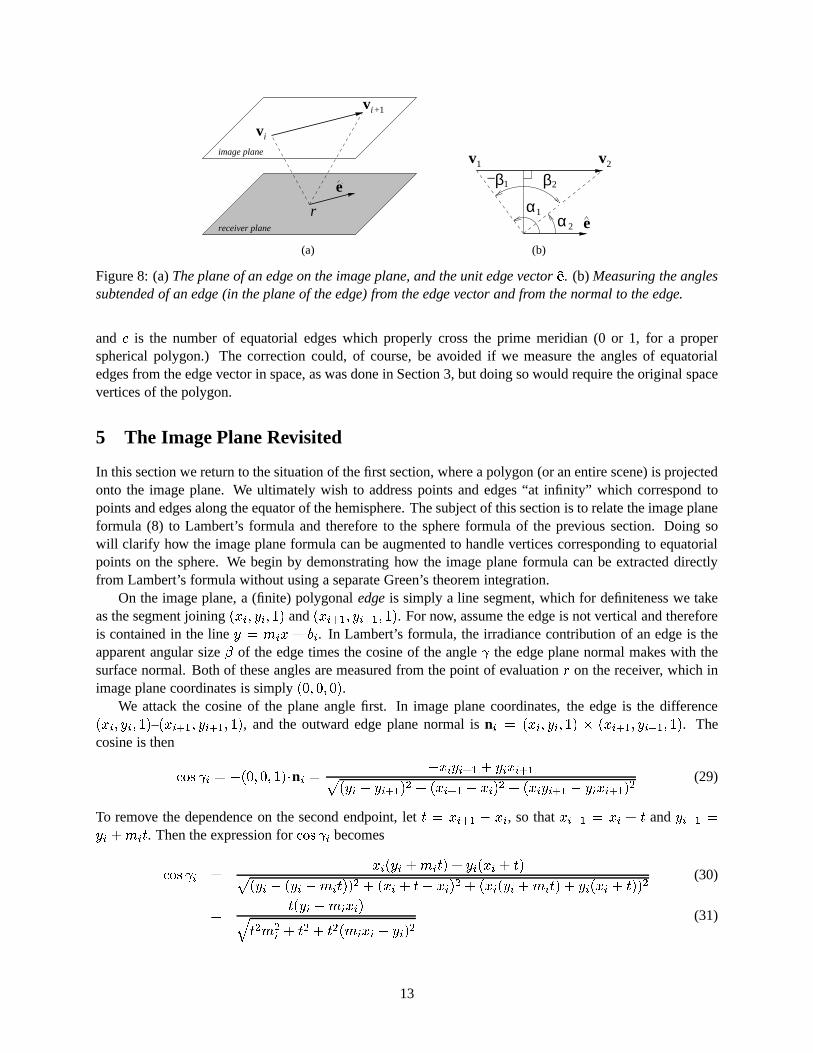
Figure 8: (a)The plane of an edge on the image plane, and the unit edge vectore. (b) Measuring the anglessubtended of an edge (in the plane of the edge) from the edge vector and from the normal to the edge.
and c is the number of equatorial edges which properly cross the prime meridian (0 or 1, for a properspherical polygon.) The correction could, of course, be avoided if we measure the angles of equatorialedges from the edge vector in space, as was done in Section 3, but doing so would require the original spacevertices of the polygon.
5 The Image Plane Revisited
In this section we return to the situation of the first section, where a polygon (or an entire scene) is projectedonto the image plane. We ultimately wish to address points and edges “at infinity” which correspond topoints and edges along the equator of the hemisphere. The subject of this section is to relate the image planeformula (8) to Lambert’s formula and therefore to the sphere formula of the previous section. Doing sowill clarify how the image plane formula can be augmented to handle vertices corresponding to equatorialpoints on the sphere. We begin by demonstrating how the image plane formula can be extracted directlyfrom Lambert’s formula without using a separate Green’s theorem integration.
On the image plane, a (finite) polygonaledgeis simply a line segment, which for definiteness we takeas the segment joining(xi; yi; 1) and(xi+1; yi+1; 1). For now, assume the edge is not vertical and thereforeis contained in the liney = mix + bi. In Lambert’s formula, the irradiance contribution of an edge is theapparent angular size of the edge times the cosine of the angle the edge plane normal makes with thesurface normal. Both of these angles are measured from the point of evaluationr on the receiver, which inimage plane coordinates is simply(0; 0; 0).
We attack the cosine of the plane angle first. In image plane coordinates, the edge is the difference(xi; yi; 1)–(xi+1; yi+1; 1), and the outward edge plane normal isni = (xi; yi; 1) (xi+1; yi+1; 1). Thecosine is then
cos i = (0; 0; 1)ni = xiyi+1 + yixi+1p(yi yi+1)2 + (xi+1 xi)2 + (xiyi+1 yixi+1)2
(29)
To remove the dependence on the second endpoint, lett = xi+1 xi, so thatxi+1 = xi + t andyi+1 =yi +mit. Then the expression forcos i becomes
cos i =xi(yi +mit) + yi(xi + t)p
(yi (yi mit))2 + (xi + t xi)2 + (xi(yi +mit) + yi(xi + t))2(30)
=t(yi mixi)q
t2m2i + t2 + t2(mixi yi)2
(31)
13

=s(yi mixi)q
1 +m2i + (mixi yi)2
; (32)
wheres = sgn(t) is the direction, of sorts, of the edge on the image plane.The same trick used to compute the angle by measuring from the edge vector (see Section 3) can be
used here. The edge vector, as illustrated in Figure 8, is
e =sq
1 +m2i
(1;mi; 0) (33)
and the vertex vectors are
v1 =(xi; yi; 1)p1 + xi + yi
; v2 =(xi+1; yi+1; 1)p1 + xi+1 + yi+1
(34)
The angle of the edge is the difference of the vertex angles measured from the edge vector. We have, forv1,
cos1 = ev1 =s(xi +miyi)q
(1 +m2i )(1 + x2i + y2i )
: (35)
However, the image plane formula involves inverse tangents rather than inverse cosines. To match theformulation, we use the following identity for first-quadrant angles
arccosa
c= arctan
pc2 a2
a=
2 arctan
apc2 a2
(36)
and thereby obtain
1 =
2 arctan
s(xi +miyi)q1 +m2
i + (yi mixi)2(37)
Using1 = =2 1, the angle ofv1 measured from the perpendicular in the edge plane (as illustrated inFigure 8, and corresponding to measuring from the acme of the arc in the previous section) the arctangentconversion remains valid if the numeratorxi + miyi becomes negative; the angle1 likewise becomesnegative, as it is measured. Then the angle of the edgei is the difference21 (2 computed analogouslyto 1) and we obtain
i = s
0@arctan
xi+1 +mi+1yi+1q1 +m2
i+1 + (yi+1 mi+1xi+1)2 arctan
xi +miyiq1 +m2
i + (yi mixi)2
1A : (38)
The term for the edge is the producti cos i in which the sign terms cancel (s2 = 1) and we have0@arctan
xi+1 +mi+1yi+1q1 +m2
i+1 + (yi+1 mi+1xi+1)2 arctan
xi +miyiq1 +m2
i + (yi mixi)2
1A (yi mixi)q
1 +m2i + (mixi yi)2
(39)which matches the formula developed from Green’s theorem—but where is the second term? Recall thedevelopment in the section thus far has assumed that the the edge on the image plane is not vertical.
14

5.1 Vertical edges
Suppose now that the edge joining(xi; yi; 1) and(xi+1; yi+1; 1) is vertical. In this case, the line equation issimplyx = xi or x = xi+1 and the expression forcos i reduces to
cos i = sxiq1 + x2i
(40)
wheres = sgn(yi+1 yi), and the edge angle becomes
i = s
0@arctan
yi+1q1 + x2i+1
arctanyiq
1 + x2i
1A : (41)
Again thes signs cancel in the product.While equation (41) matches the first term in the expression for theF in the Green’s Theorem evaluation,
there is a problem, because that summationexcludedvertical edges. Yet the previous equation shows thatvertical edges have a definite contributionvia Lambert’s summation. This can be reconciled by adding theterms
xiq1 + x2i
arctanyiq
1 + x2i
xi+1q1 + x2i+1
arctanyi+1q1 + x2i+1
(42)
to the Lambert term for each non-vertical edge. The terms telescope for adjacent non-vertical edges, so if thesummation excludes vertical edges the required terms for the vertical edges will remain in the summation.It is left to the reader to verify that this does indeed produce exactly the same formula as the one developeddirectly from Green’s Theorem.
5.2 Remarks
The results in this section show how the terms of the image plane formula correspond to the equivalent termswhich are obtained from Lambert’s formula. This correspondence will be exploited in the next section, tomerge the expressions obtained from the sphere formula to vertices and edges “at infinity” in the imageplane.
6 The Projective Plane
A restriction of the the image plane formula developed in Section 2 is that it requires the polygon to liestrictly above the receiver plane (thexy-plane), whereas Lambert’s formula allows the polygon to havevertices or edges actually on the receiver plane. A polygon having a vertex or an edge on the receiver planewill project to an unbounded polygon on the image plane, as illustrated in Figure 9. When a single vertexlies on the receiver plane, the projected polygon has a vertex “at infinity”; when an edge lies on the receiverplane, the projected polygon has an edge “at infinity”. In this section we shall augment the image planeformula to handle such unbounded polygons, by working in the real projective plane [8].
The projective plane arises naturally from the perspective projection used in Section 2. A point(x; y; z)in space withz 6= 0 projects to the point(x=z; y=z; 1) on the image plane. Points on thexy-plane do notproject to the image plane, rather they project topoints at infinity.
In fact, the image plane we have used, the plane parallel to thexy-plane one unit above, matches thehomogeneous representation of the projective plane. Points on the projective plane are eitherfinite points,represented as(x; y; 1) or points at infinity, which are represented as(a; b; 0); any nonzero multiple of apoint at infinity is the same point at infinity.
15

The projective plane is not a vector space, but a vector can be defined as the difference of any two finitepoints, thus having the form form(a; b; 0). A vector represents a direction on the finite plane in a mannersimilar to a point at infinity, with one important difference. Without giving formal definitions, a vector anda point at infinity differ in that a negative multiple of a point at infinity results in the same point, while sucha multiple reverses the direction of a vector. For this reason, we shall refer to the direction of a vector as asigned direction, and a point at infinity as aprojective direction.
6.1 Reformulation on the Finite Plane
The vertex-based formulation works on the finite projective plane (which excludes points at infinity) in thesame manner as in Section 2. However, it is more natural to replace the edge slopes with projective direc-tions. A line with slopem, regardless of its position on the finite plane, intersects the unique point at infinity(1;m; 0); a vertical line intersects(0; 1; 0). The slope of a line may therefore be generally represented bythe point at infinity(a; b; 0) where, for a line with finite slope,m = a=b and for a vertical line we usea = 0,b = 1.
For a non-vertical edge, replacingm with b=a in equation produces
ax+ bypa2 + b2 + (bx ay)2
arctanay bxp
a2 + b2 + (bx ay)2(43)
which not only becomes more symmetric, but reduces immediately to equation (41) for a vertical edge.Using projective directions rather than the slopes of the incoming and outgoing edges thus results in acleaner formulation. It is worth stating the formulation specifically:
I =M
2
nXi=1
~F (xi; yi; ai1; bi1) ~F (xi; yi; ai; bi): (44)
where~F (x; y; a; b) =
ax+ bypa2 + b2 + (bx ay)2
arctanay bxp
a2 + b2 + (bx ay)2(45)
and(ai; bi) is the projective direction of edgei. Equation (44) provides an alternative to the original imageplane formula (8) that eliminates the extra condition for vertical edges. Also the projective directions of theedges are easy to compute:(ai; bi) = (xi+1 xi; yi+1 yi), and any multiple of this direction, including anegative multiple, remains valid.
6.2 Vertices at Infinity
The primary goal is to develop a vertex-based formula which works on the polygon in the space in its naturalrepresentation without referring to the original polygon. In this case the natural representation of a projectivepolygon is it terms of projective points. At first glance, it might appear that because the projective directionof an edge going to infinity is identical to that point at infinity the formula would be simpler still, but this isnot the case. As we shall see, thesigneddirection of the edges incident on an infinite vertex are needed fora vertex at infinity.
For a concrete example, consider the term for a vertical edge
xip1 + xi
arctan
yi+1p1 + xi+1
arctanyip
1 + xi
:
The first term approaches=2 asyi+1 approaches infinity, but=2 asyi+1 approaches negative infinity.However, in both cases the vertex at infinity is represented by(0; 1) (0;1) in the projective plane, and
16

(a) (b)
(c) (d)
Figure 9: (a)A vertex that lies on the receiver plane projects to a vertex at infinity on the projective plane,resulting in an unbounded polygon with parallel edges approaching infinity.(b) The projected polygon ina disc representation of the projective plane. The edges are contained in lines which meet at diametricallyopposite points; these two points together are the single point at infinity.(c) An edge on the receiver planeprojects to an edge at infinity on the projective plane, resulting in two non-parallel edges which go to infinity.(d) The infinite edge represented in the projective plane.
if only the vertex and the incoming direction is used to represent the vertex, there is no way to distinguishthe sign of the=2 term.
The local characterization of a vertex at infinity therefore requires a signed direction(a; b; 0) (whichwithout the direction is also the point at infinity on which the vertex lies) and an arbitrary point(xin; yin; zin)and(xout; yout; zout) on each incident edge. Either point may be a point at infinity. A finite vertex requiresonly a projective (unsigned) direction, and the position of the vertex itself provides the point on the edge.
Now consider the case of an edge terminating at a vertex at infinity. The characterization of the incomingedge at the vertex requires an arbitrary (finite) point on the edge(xin; yin; 1) and a signed direction(a; b; 0).As we have seen, the term for the incoming edge is the product of thecos term and the angle measuredfrom the near point on the line containing the edge. The former is computed as in Equation (23), while thelatter is the limiting value=2—the sign is always positive for an incoming edge. For an outgoing edge, thecosine term is the same, but the angular term is always=2. Note that because of this thes terms fromSection 5 do not cancel and it is therefore necessary to use a signed direction for the edge.
6.3 Edges at Infinity
The case of an edge at infinity corresponds to an edge on the equator of the sphere. The cosine of the edgeangle is always 1, and the angular size can be computed in a manner analogous to the longitude subtractionwhich we did on the sphere. There is a topological problem, however; an infinite edge in the projectiveplane is not well represented by a circular arc, rather it is a pair of antipodal arcs. This is not a problem if weassume each infinite edge comes from a real polygonal edge, and thus cannot span more than a semi-circle inthis representation. The angle of the edge is the difference of the angle each endpoint makes with the pointat infinity (0; 1; 0): the contribution of an incoming edge at infinity to(x; y; 0) is the anglearctan(x=y), for
17

an outgoing edge, it is the negative.Again, we have the problem with an edge at infinity which crosses the point(1; 0; 0); in this case an
extra correction of must be added. Again, if we measure the angles from the edge vector of the polygonthe correction can be avoided; this is done in the next subsection.
Combining the expressions for vertices and edges at infinity with the finite edge formulations of theprevious section we obtain a complete formula for polygons on the image plane, including unboundedpolygons. All the terms are collected in Figure 6.4. Notice we have not attempted to unify the terms for thevarious cases into a single expression.
6.4 Formulation in Homogeneous Coordinates
The development in the previous subsection developed a vertex-based formula for irradiance from a polygonsituated and represented in the real projective plane without referring to the original polygon. An argumentcould be made that the projective plane is not the proper setting for computing irradiance, because antipodalpoints at infinity are most definitely not the same point; the fact that the signed direction for points at infinitywas needed exemplifies this. In this section we amend the formula so that it applies to the homogeneouscoordinates of the projected polygon. The principal difference is that we omit points at infinity outright andsimply use the coordinates of vertices which line on the receiver plane directly.
Consider the vertices of the projected polygonP in homogeneous image plane coordinates. We makethe assumption that vertices which lie on the receiver plane,i.e. with z-coordinate 0, remain unaffected bythe perspective projection. The polygon vertices are then of the form(xi; yi; zi) wherezi is either 0 or 1.
Each edge has a direction vector. The edge joining two finite vertices has direction(xi+1 xi; yi+1 yi; 0), the vector difference on the image plane. For the edge joining two vertices at infinity,i.e. two verticeson the receiver plane, we use the same vector. The direction of an edge going to a vertex at infinity is simplythat vertex at infinity(xi; yi; 0), and the negative for an edge leaving a vertex at infinity. Again, to properlyspecify the “local behavior” of an edge going to (or coming from) a vertex at infinity we require an arbitrarypoint on the edge.
We previously assumed that each vertex of the projective polygon is either a finite point or a point atinfinity. That is, points at infinity did not have a direction. In the homogeneous representation, a vertex atinfinity has the coordinates of the vertex on the receiver plane, and as such has a definite direction (that is,a negative multiple of the point produces a vertex in the opposite direction—again, on the projective planethese points are the same.) So rather than using a signed direction of the edge going to a point at infinity, wecan use the homogeneous point itself.
To measure the angular span of an edge at infinity, we shall measure against the edge vector on thereceiver plane—this eliminates the need for the correction in the previous section. We have, as in Section 5
i;1 = arccos(xi; yi; 0)(ai; bi; 0)qx2i + y21
qa2i + b2i
=
2 arctan
aixi + biyijbixi aiyij
where(xi; yi; 0) is either point on the edge and(ai; bi; 0) is the direction of the edge. The term for the edgeis therefore
arctanaixi+1 + biyi+1jbixi+1 aiyi+1j arctan
aixi + biyijbixi aiyij (46)
This naturally leads to a vertex-based expression, where the edge vector(ai; bi; 0) is replaced by the appro-priate incoming or outgoing edge direction vector. Figure 6.4 contains a complete list and description of allthe terms.
18

incoming edge outgoing edge
edge C(ainy binx) arctan [C(ainx+ biny)] C(aouty boutx) arctan [C(aoutx+ bouty)]
vertical edge Ax arctan(Ay) Ax arctan(Ay)
vertex at infinity
2C(ainyin binxin)
2C(aoutyout boutxout)
edge at infinity arctanx
y arctan
x
y
Where
A =1p
1 + x2; C =
1pa2 + b2 + (bx ay)2
The terms for the vertical edges are redundant but included for completeness. Each projective vertex is a finite vertexor point at infinity, each is of the form(x; y; 0). Each incident edge has a signed direction(a; b; 0). Thexin andyinvalues in the terms for a vertex at infinity are arbitrary points on the incoming edge; the “out” values are those of theoutgoing edge. A correction of must be added if an edge at infinity crosses(1; 0; 0). The irradiance is the sum of theterms and the correction scaled byM=2.
Figure 10: Terms for the vertex-based irradiance formulated in the projective plane.
incoming edge outgoing edge
edge C(ainy binx) arctan [C(ainx+ biny)] C(aouty boutx) arctan [C(aoutx+ bouty)]
vertical edge Ax arctan(Ay) Ax arctan(Ay)
vertex at infinity
2C(xyin yxin)
2C(xyin yxout)
edge at infinity arctanainx+ biny
jbinx ainyj arctanaoutx+ bouty
jboutx aoutyj
Where
A =1p
1 + x2; C =
1pa2 + b2 + (bx ay)2
The terms for the vertical edges are redundant but included for completeness. Each homogeneous vertex is a eitherfinite vertex of the form(x; y; 1) or a vertex at infinity of the form(x; y; 0), in image plane coordinates. Each incidentedge has an unsigned direction(a; b; 0). Thexin andyin values in the terms for a vertex at infinity are arbitrary pointson the incoming edge; the “out” values are those of the outgoing edge. The irradiance is the sum of the terms scaledbyM=2.
Figure 11: Terms for the vertex-based irradiance formulated in homogeneous coordinates.
19

7 Conclusion
This report has detailed several vertex-based formulas for irradiance due to a uniformly emitting polygon.Each has advantages and disadvantages. The image plane formula from Section 2 is the simplest and per-haps the most computationally efficient, but suffers from the restriction that the polygon is not allowed toimpinge the receiver plane. The reformulation of Lambert’s formula given by Equation (12) works withouttransforming the polygon and has perhaps the cleanest formulation but does not immediately generalize tothe apparent intersection of polygons. The sphere formula of Section 4 was introduced primarily to guidethe extension of the image plane formula to unbounded polygons, and these formulas given in Section 6have extra “ifs”. We hope the vertex-based formulations for irradiance developed here will provide a usefulalternative to Lambert’s formula.
References
[1] James Arvo. The irradiance Jacobian for partially occluded polyhedral sources. InSiggraph ’94, pages 343–350,July 1994.
[2] James Arvo.Analytic Methods for Simulated Light Transport. PhD thesis, Yale University, 1995.
[3] P. Atherton, K. Weiler, and D. Greenberg. Polygon shadow generation. volume 12, pages 275–281, August 1978.
[4] Michael F. Cohen and John R. Wallace.Radiosity and Realistic Image Synthesis. Academic Press Professional,Cambridge, MA, 1993.
[5] George Dretakkis and Eugene Fiume. A fast shadow algorithm for area light sources using backprojection.In Andrew Glassner, editor,Proceedings of SIGGRAPH ’94 (Orlando, Florida, July 24–29, 1994), ComputerGraphics Proceedings, Annual Conference Series, pages 223–230. ACM SIGGRAPH, ACM Press, July 1994.ISBN 0-89791-667-0.
[6] David Hart, Philip Dutre, and Donald P. Greenberg. Direct illumination with lazy visibility evaluation.Proceed-ings of SIGGRAPH 99, pages 147–154, August 1999. ISBN 0-20148-560-5. Held in Los Angeles, California.
[7] T. Nishita and E. Nakamae. Continuous tone representation of three-dimensional objects taking account ofshadows and intereflection. InComputer GraphicsProceedings, Annual Conference Series, ACM SIGGRAPH,pages 23–30, July 1985.
[8] R. F. Riesenfeld. Homogeneous coordinates and projective planes in computer graphics.IEEE Computer Graph-ics & Applications, 1(1):50–55, January 1981.
[9] Peter Schr¨oder and Pat Hanrahan. On the Form Factor Between Two Polygons. In James T. Kajiya, editor,SIGGRAPH 93 Conference Proceedings, Annual Conference Series, pages 163–164, 1993. ISBN 0-89791-601-8.
[10] Francois Sillion and Claude Puech.Radiosity and Global Illumination. Morgan Kaufmann, San Francisco, 1994.
[11] Cyril Soler and Franc¸ois X. Sillion. Fast Calculation of Soft Shadow Textures Using Convolution. In MichaelCohen, editor,SIGGRAPH 98 Conference Proceedings, Annual Conference Series, pages 321–332. ACM SIG-GRAPH, Addison Wesley, July 1998. ISBN 0-89791-999-8.
[12] Michael M. Stark, Elaine Cohen, Tom Lyche, and Richard F. Riesenfeld. Computing exact shadow irradianceusing splines.Proceedings of SIGGRAPH 99, pages 155–164, August 1999. ISBN 0-20148-560-5. Held in LosAngeles, California.
[13] Michael M. Stark and Richard F. Riesenfeld. Exact illumination in polygonal environments using vertex tracing.Eleventh Eurographics Workshop on Rendering (to appear), June 2000.
[14] Andrew Woo, Pierre Poulin, and Alain Fournier. A survey of shadow algorithms.IEEE Computer Graphics andApplications, 10(6):13–32, November 1990.
20