vertexrsi c240mt 2.4m trailer mounted satcom terminaltrailer mounted satcom terminal description the...
TRANSCRIPT

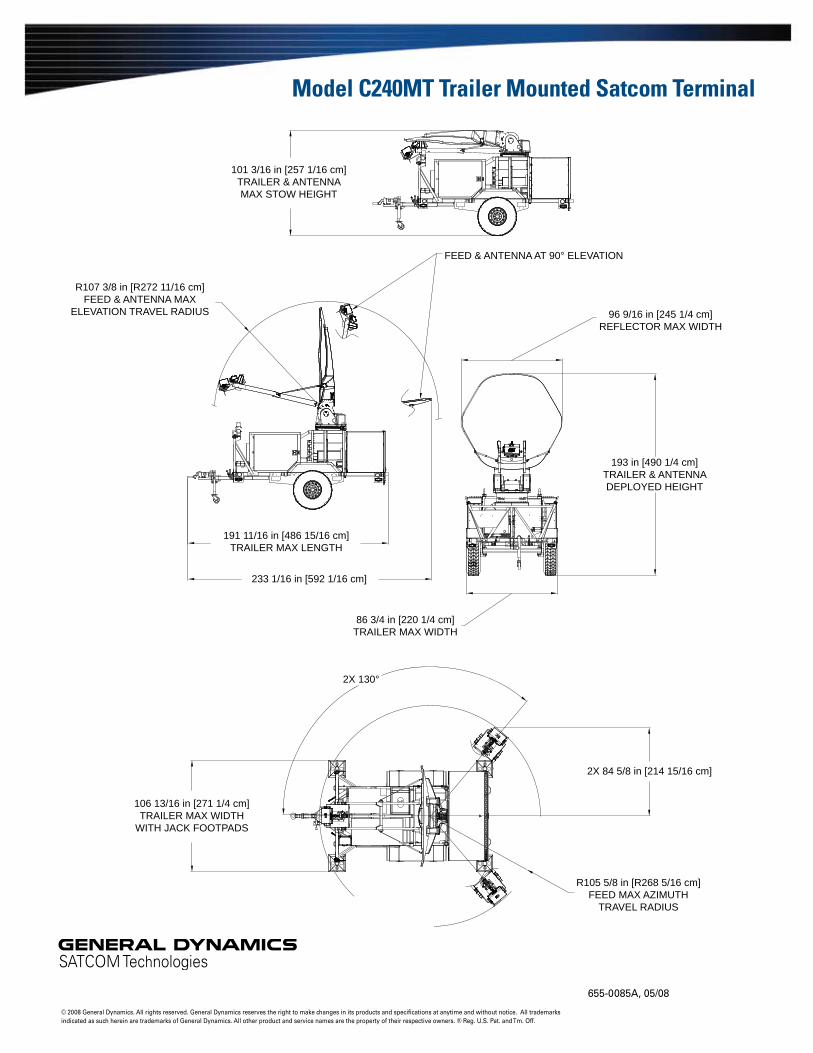
Model C240MTTrailer Mounted Satcom Terminal
DescriptionThe VertexRSI lightweight commercial 2.4-meter Trailer Mounted Satcom Terminal is designed for worldwide transmit and receive operation in C, X, Ku and Ka-band. This mobile terminal consists of a 2.4-meter tracking antenna mounted on a rugged chassis equipped with a generator and environmentally controlled rack enclosure. This configuration results in a low-weight tow package with superior features and high performance under wind-loading conditions. The accurate reflector surface provides exceptionally low sidelobe and cross-polarization performance well within INTELSAT and EUTELSAT requirements. The interchangeable feeds are palletized for quick, easy removal and replacement, allowing the end-user to effectively change frequency bands in the field within minutes. HPAs can be boom mounted for minimal WG losses per the customer’s requirements. The onboard generator provides power to the UPS, ECU, and all the rack-mounted equipment located in the 38 rack-unit electronics enclosure. The entire terminal can be controlled through the M&C system as part of the 323T tracking controller (optional). The commercial 323T ACU provides auto-acquisition and several optional tracking algorithms including adaptive tracking in high winds.
FeaturesSingle offset carbon-fiber reflector �
High performance �
Low sidelobes, high EIRP capability, compliant under operational wind �conditions
Stow/deployment �
Low profile, stow position on vehicle, precision alignment, automatic deploy �and stow
INTELSAT type approved for C/Ku-band, EUTELSAT compliant �
Safety equipment, brakes, lights, pintle hitch �
OptionsReflector (single or three-piece segmented) �
Finishes (white or per customer spec) �
Integration (various TWT/amplifier mounting arrangements) �
Anti-icing �
Troposcatter capable �
ACU built-in M&C and spectrum analyzer �
Adaptive tracking �
HMMWV tires/wheels �
Full-featured auto-acquire tracking controller
Compact transit configuration for aircraft transit
Multiband antenna system with rapid interchange between C, X, Ku and Ku-band feeds
Motorized cable drive positioner
38 RU Electronics Enclosure Unit (EEU)
7.5 kW generator and 3 kW UPS
The Strength to Perform

Technical SpecificationsMechanicalTravel Az = ±130° continuous; El = 0 - 90° of reflector boresight; polarization = ±90°EEU (Electronics Enclosure Unit) 2 each 19 rack units, weatherized access doorECU (Environmental Control Unit) 9,000 BTU cooling, 1.9 kW heatingReflector 2.4-meter carbon fiber (single or three-piece configuration)Feed Multiband interchangeable, C, X, Ku and Ka options including troposcatterFinish White (standard; other optional finishes also available)Weight 4,000 lbs w/single feed + HPA (typical), GVW = 4,200 lbsL x W x H1 192 in. x 97 in. x 102 in. stowedElectrical Interface (Auto-transformer) 120/240 VAC 50/60 Hz shore powerGenerator 7.5 kW, 120 VAC, 60 Hz, 24 gal. diesel tankUPS 3 kW, 120 VAC, 60 HzStorage Cabinet 27 cubic foot weatherproofPower Consumption 1 gal. diesel/hr., 2900 KVA + ECU (1.9 kW)Chassis Torsion axles, inertial brakes, safety lights, high-flotation tires, pintle hitch
EnvironmentalWind Loading Operational 45 mph (72 km/h) gusting to 60 mph (97 km/h) Survival 60 mph (97 km/h) gusting to 80 mph (129 km/h) any position5
90 mph (145 km/h) stow positionPointing Loss (operational winds) 2.0 dB peak (Ka-band Rx), performance dependent on controller options and anchoringTemperature Operational -22° to +122° F (-30° to +50° C) Survival -40° to +158° F (-40° to +70° C)Rain Operational: 4 in/h (10 cm/h); Survival: 6 in/h (15 cm/h)Relative Humidity 0% to 100% with condensationSolar Radiation 360 BTU/h/ft2 (1000 Kcal/h/m2)Radial Ice (survival) 1 in (25 mm) on all surfaces, 1/2 in (12 mm) on all surfaces with 60 mph (95 km/h) wind gustsCorrosive Atmosphere As encountered in coastal regions and/or heavily industrialized areasTransport Munson road tested, rail impact
1 Three-piece reflector option reduces width to 87 in.2 Angular values for Ka-band are 1° to 30°, 30° to 130° and 130° to 180°.3 Ku-band is Intelsat Type Approved with the following note on Noise Temperature: 73.7 K, 10° elevation, 11 GHz.4 X-band feed includes high isolation filter.5 Tie downs required.

Model C240MT Trailer Mounted Satcom TerminalC-Band 2-Port
Linear PolarizedC-Band 2-Port
Circular PolarizedX-Band 2-Port
Circular PolarizedKu-Band 2-Port Linear Polarized
Ku-Band 4-Port Linear Polarized
Ka-Band 2-Port Circular Polarized
Electrical Receive Transmit Receive Transmit Receive Transmit Receive Transmit Receive Transmit Receive TransmitFrequency (GHz) 3.625 -
4.2005.850 - 6.425
3.625 - 4.200
5.850 - 6.425
7.250 - 7.750
7.900 - 8.400
10.950 - 12.750
13.750 - 14.500
10.950 - 12.750
13.750 - 14.500
20.200 - 21.200
30.000 - 31.000
Antenna Gain at Midband, dBi 38.20 42.00 38.06 42.10 43.50 43.60 47.19 49.00 47.10 48.80 52.30 55.20Antenna Noise Temperature 5° Elevation 49 K 51 K 68 K 63 K 85 K 143 K 10° Elevation 38 K 50 K 59 K 60 K3 75 K 123 K 20° Elevation 33 K 49 K 55 K 56 K 69 K 109 K 40° Elevation 34 K 48 K 55 K 55 K 68 K 101 KTypical G/T at 4.0 & 7.5 GHz20° Elevation, Clear Horizon C-Band 35° K LNA 19.5 dB/K X-Band 55° K LNA 23.1 dB/KTypical G/T at 4.0 & 10.95 GHz10° Elevation, Clear Horizon C-Band 35° K LNA 18.8 dB/K C-Band 50° K LNA 18.1 dB/K Ku-Band 70° K LNA 25.4 dB/K Ku-Band 90° K LNA 24.7 dB/KTypical G/T at 11.85 GHz20° Elevation, Clear Horizon Ku-Band 70° K LNA 25.7 dB/K Ku-Band 90° K LNA 25.1 dB/KTypical G/T at 20.70 GHz20° Elevation, Clear Horizon Ka-Band 120° K LNA 28.7 dB/K Ka-Band 200° K LNA 27.4 dB/KPattern Beamwidth (in degrees at midband) -3 dB Beamwidth 2.12 1.37 2.09 1.35 1.11 1.03 0.72 0.60 0.71 0.60 0.40 0.29 -15 dB Beamwidth 4.45 2.88 4.39 2.84 2.33 2.16 1.51 1.26 1.49 1.26 0.84 0.61Sidelobe Performance2
For Angle A from 2° to 30° (typical) 29-25 Log A 29-25 Log A 29-25 Log A For Angle A beyond 29-25 Log A 29-25 Log A 29-25 Log A mainbeam to 20° For Angle A from 30° to 130° -10 dBi -10 dBi -10 dBi -10 dBi -10 dBi -10 dBi For Angle A from 130° to 180° 0 dBi 0 dBi 0 dBi 0 dBi 0 dBi 0 dBiCross Polarization On Axis 30.0 dB 30.0 dB 19.7 dB 27.3 dB 21.3 dB 21.3 dB 35.0 dB 35.0 dB 35.0 dB 35.0 dB 24.8 dB 24.8 dB Within 1.0 dB BW 28.0 dB 28.0 dB 19.7 dB 27.3 dB 21.3 dB 21.3 dB 27.0 dB 35.0 dB 27.0 dB 35.0 dB 24.8 dB 24.8 dBVSWR 1.30:1
(17.7 dB)1.30:1
(17.7 dB)1.30:1
(17.7 dB)1.30:1
(17.7 dB)1.30:1
(17.7 dB)1.30:1
(17.7 dB)1.35:1
(16.5 dB)1.25:1
(19.0 dB)1.35:1
(16.5 dB)1.30:1
(17.7 dB)1.30:1
(17.7 dB)1.30:1
(17.7 dB)Axial Ratio 1.81 dB 0.75 dB 1.50 dB 1.50 dB 1.00 dB 1.00 dBPort-to-Port Isolation Rx/Tx (Rx frequency) 0 dB -30 dB 0 dB -50 dB 0 dB -110 dB 0 dB -30 dB 0 dB -50 dB 0 dB -50 dB Tx/Rx (Tx frequency) -60 dB 0 dB -100 dB 0 dB -110 dB 0 dB -85 dB 0 dB -85 dB 0 dB -85 dB 0 dBFeed Insertion Loss 0.15 dB 0.15 dB 0.40 dB 0.20 dB 0.45 dB 1.00 dB4 0.30 dB 0.20 dB 0.60 dB 0.45 dB 0.30 dB 0.30 dBWaveguide Interface Flange CPR-
229GCPR-137G
CPR-229G
CPR-137GCPR-112G
CPR-137GWR-75
FlatWR-75 Flat
WR-75 Flat
WR-75 FlatWR-42
FlatWR-28
FlatWaveguide Interface Az Axis CPR-
137GCPR-137G CPR-137G WR-75 Flat WR-75 Flat
WR-34 Flat
Total Power Handling Capability 2 kW CW 2 kW CW 2 kW CW 1 kW CW 2 kW CW 250 W CWRF Specification 975-2837 975-2712 975-10124 975-15753 975-1708 975-2901
Model C240MT Trailer Mounted Satcom Terminal
655-0085A, 05/08
© 2008 General Dynamics. All rights reserved. General Dynamics reserves the right to make changes in its products and specifications at anytime and without notice. All trademarks indicated as such herein are trademarks of General Dynamics. All other product and service names are the property of their respective owners. ® Reg. U.S. Pat. and Tm. Off.
R107 3/8 in [R272 11/16 cm]FEED & ANTENNA MAX
ELEVATION TRAVEL RADIUS
R105 5/8 in [R268 5/16 cm]FEED MAX AZIMUTH
TRAVEL RADIUS
193 in [490 1/4 cm]TRAILER & ANTENNADEPLOYED HEIGHT
106 13/16 in [271 1/4 cm]TRAILER MAX WIDTH
WITH JACK FOOTPADS
191 11/16 in [486 15/16 cm]TRAILER MAX LENGTH
233 1/16 in [592 1/16 cm]
2X 84 5/8 in [214 15/16 cm]
2X 130°
101 3/16 in [257 1/16 cm]TRAILER & ANTENNAMAX STOW HEIGHT
96 9/16 in [245 1/4 cm]REFLECTOR MAX WIDTH
86 3/4 in [220 1/4 cm]TRAILER MAX WIDTH
FEED & ANTENNA AT 90° ELEVATION