vertical ball screw scissors lift...vertical ball screw scissors lift p.o. box 1058 1058 west...
TRANSCRIPT
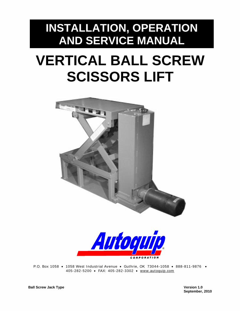
VERTICAL BALL SCREW
SCISSORS LIFT
P.O. Box 1058 1058 West Industrial Avenue Guthrie, OK 73044-1058 888-811-9876 405-282-5200 FAX: 405-282-3302 www.autoquip.com
Ball Screw Jack Type Version 1.0
September, 2010
INSTALLATION, OPERATION AND SERVICE MANUAL
2
© 2010 AUTOQUIP CORPORATION
This manual and the information herein is the sole property of Autoquip Corp. and shall not be reproduced without written consent by Autoquip
3
Introduction 4 Identification and Inspection 5 Responsibility of Owners / Users 6 Safety Signal Words 7 Safety Practices 8 Label Identification 11 Lift Specifications 14 Actuator Specifications 15 Lift Blocking Instructions 16 Installation Instructions 19 Operating Instructions 22 Routine Maintenance 24 General Maintenance 26 Replacement Parts List 32 Lift Troubleshooting 33 Actuator Troubleshooting 35
Please record the following information and refer to it when calling your dealer or Autoquip.
Model Number:________________Serial Number: ___________________ Installation Date _____/_____/_____
TABLE OF CONTENTS
4
IMPORTANT
Please read and understand this manual prior to operation of this lift. Failure to do so could lead to property damage and/or serious personal injury. If any questions should arise, call a local representative or Autoquip Corporation at 1-888-811-9876. Autoquip Corporation has designed and manufactured this lift to safely and efficiently move materials between multiple levels via mechanical actuation. It has been built to provide many years of dependable service. Proper installation of this equipment is vital to both the efficiency of the unit and the ultimate satisfaction of the end user. It is vital for the installers to read and understand this manual! These instructions have been prepared and organized to assist the installers and it is important for these individuals to carefully follow the steps in the order they are presented! Situations may arise which are not covered in these installation instructions. If you have questions, please call Autoquip Customer Service at (405) 282-5200 or 1-888-811-9876.
PLANNED MAINTENANCE PROGRAM A local Autoquip representative provides a Planned Maintenance Program (PMP) for this equipment using factory-trained personnel. Call a local representative or Autoquip Corporation at 1-888-811-9876 or 405-282-5200 for more information.
INTRODUCTION

5
IDENTIFICATION When ordering parts or requesting information or service on this equipment, PLEASE REFER TO THE MODEL AND SERIAL NUMBER. This information is on a nameplate attached to the leg assembly. Replacement parts are available from a local Autoquip distributor.
INSPECTION
Immediately upon receipt of the unit, a visual inspection should be made to determine that it has not been damaged in transit. Any damage found must be noted on the delivery receipt. In addition to this preliminary inspection, the unit should be carefully inspected for concealed damage. Any concealed damage found that was not noted on the delivery receipt should be reported in writing to the delivering carrier within 48 hours.
The following is a checklist that will aid in the inspection of this equipment. 1. Examine the entire unit for any signs of mishandling. 2. Pay special attention to gearboxes, mechanical actuators & wiring. 3. After installation, raise and block the lift and inspect the base frame, scissors
assembly and mechanical drive system. See the “Lift Blocking Instructions” section.
IDENTIFICATION & INSPECTION
6
DEFLECTION It is the responsibility of the user/purchaser to advise the manufacturer where deflection may be critical to the application. INSPECTION & MAINTENANCE The lift shall be inspected and maintained in proper working order in accordance with Autoquip’s operating/maintenance (O&M) manual and with other applicable safe operating practices. REMOVAL FROM SERVICE Any lift not in safe operating condition such as, but not limited to, excessive leakage, missing rollers, pins, or fasteners, any bent or cracked structural members, cut or frayed electric lines, damaged or malfunctioning controls or safety devices, etc. shall be removed from service until it is repaired to the original manufacturer’s standards. REPAIRS All repairs shall be made by qualified personnel in conformance with Autoquip’s instructions. OPERATORS Only trained personnel and authorized personnel shall be permitted to operate the lift. BEFORE OPERATION Before using the lift, the operator shall have:
Read and/or had explained, and understood, the manufacturer’s operating instructions and safety rules.
Inspected the lift for proper operation and condition. Any suspect item shall be carefully examined and a determination made by a qualified person as to whether it constitutes a hazard. All items not in conformance with Autoquip’s specification shall be corrected before further use of the lift.
DURING OPERATION The lift shall only be used in accordance with Autoquip’s O&M manual.
Do not overload the lift. Ensure that all safety devices are operational and in place.
MODIFICATIONS OR ALTERATIONS Modifications or alterations to industrial lifting equipment shall be made only with written permission of Autoquip. Autoquip does not foresee and does not anticipate unauthorized modifications, and these changes or alterations are grounds for voiding all warranties.
RESPONSIBILTY OF OWNERS/USERS
7
SAFETY ALERTS (Required Reading!) The following SAFETY ALERTS are intended to create awareness of owners, operators, and maintenance personnel of the potential safety hazards and the steps that must be taken to avoid accidents. These same alerts are inserted throughout this manual to identify specific hazards that may endanger uninformed personnel. Identification of every conceivable hazardous situation is impossible. Therefore, all personnel have the responsibility to diligently exercise safe practices whenever exposed to this equipment. ____________________________________________________________
DANGER!
Identifies a hazardous situation, which, if not avoided, will result in death or severe personal injury. _____________________________________________________________
WARNING! Identifies a hazardous situation, which, if not avoided, could result in death or serious personal injury.
CAUTION!
Identifies a hazardous situation, which, if not avoided, may result in minor or moderate personal injury. _____________________________________________________________
NOTICE
Caution used without the safety alert symbol indicates a potentially hazardous situation, which, if not avoided, may result in property or equipment damage.
SAFETY SIGNAL WORDS
8
____________________________________________________________
Read and understand this manual and all labels prior to operating or servicing the scissors lift. All labels are provided in accordance with ANSI Z535.4.
DANGER!
Do not work under lift without Maintenance Device! To avoid personal injury, NEVER go under the lift platform until the load is removed and the scissors mechanism is securely blocked in the open position. See "Lift Blocking Instructions" section.
DANGER!
To avoid personal injury, stand clear of scissors mechanism while the lift is in motion.
DANGER!
Do not install the lift in a pit unless it has a bevel toe guard or other approved toe protection. A shear point can exist which can cause severe injury to the foot.
DANGER!
HIGH VOLTAGE!! Disconnect and/or lock out the electrical supply to the power unit prior to any maintenance being performed.
SAFETY PRACTICES
9
DANGER!
Scissors lifts are designed individually for a specific load and application. To avoid personal injury, do not change the load or application from the original design.
WARNING!
NEVER stand, sit or ride on the lift!
WARNING!
All warning and information decals should be in place as outlined in the “Label Identification” section. If decals are missing or damaged, they should be replaced with new ones. Contact Autoquip for replacements.
WARNING! Do not attempt to remove the drive mechanism until the maintenance locks securely support the empty lift. Failure to do so could results in personal injury or death!
WARNING!
Lift platforms traveling below floor levels may create openings, and the shape of the load and how the load is arranged on the lift may create a toe hazard as the load passes the top edge of the pit. Both situations may require guarding in accordance with Federal Regulations. Any such guarding must be installed prior to operating the lift. .
SAFETY PRACTICES
10
NOTICE
When moving the lift, do not attempt to pick it up by the platform; it is hinged and could be damaged. Pick up from under the base frame ONLY.
NOTICE Do not continue to activate the “UP” button if the lift is not raising or if it has reached the fully raised position. To do so may result in permanent damage to the lift.
NOTICE Do not continue to command lift to raise once it has reached it fully raised position. To do so may result in permanent damage tothe lift and/or ball screw jac.
NOTICE Precautions should be taken to prevent the introduction of contaminates such as dirt or other foreign material into the drive system through open fittings, pipes or disassembled components. Contamination will ruin the drive mechanism.
SAFETY PRACTICES
11
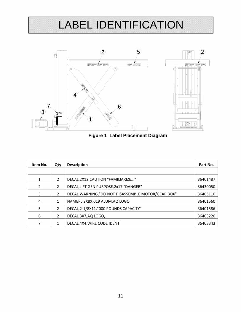
Figure 1 Label Placement Diagram
Item No. Qty Description Part No.
1 2 DECAL,2X12,CAUTION "FAMILIARIZE..." 36401487
2 2 DECAL,LIFT GEN PURPOSE,2x17 "DANGER" 36430050
3 2 DECAL,WARNING,"DO NOT DISASSEMBLE MOTOR/GEAR BOX" 36405110
4 1 NAMEPL,2X8X.019 ALUM,AQ LOGO 36401560
5 2 DECAL,2‐1/8X11,"000 POUNDS CAPACITY" 36401586
6 2 DECAL,3X7,AQ LOGO, 36403220
7 1 DECAL,4X4,WIRE CODE IDENT 36403343
52
4
6
1
73
2
LABEL IDENTIFICATION

12
Note: Labels shown here are not actual size.
Figure 2 Label 36430050
Figure 3 Label 36401586
Figure 4 Label 36401487
LABEL IDENTIFICATION
13
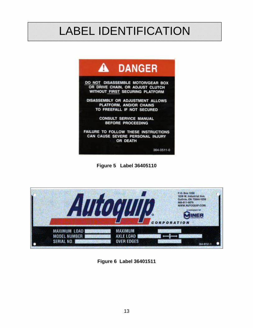
Figure 5 Label 36405110
Figure 6 Label 36401511
LABEL IDENTIFICATION
14
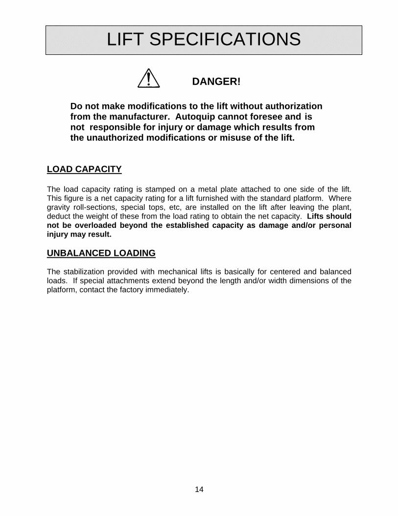
DANGER!
Do not make modifications to the lift without authorization from the manufacturer. Autoquip cannot foresee and is not responsible for injury or damage which results from the unauthorized modifications or misuse of the lift. LOAD CAPACITY The load capacity rating is stamped on a metal plate attached to one side of the lift. This figure is a net capacity rating for a lift furnished with the standard platform. Where gravity roll-sections, special tops, etc, are installed on the lift after leaving the plant, deduct the weight of these from the load rating to obtain the net capacity. Lifts should not be overloaded beyond the established capacity as damage and/or personal injury may result. UNBALANCED LOADING The stabilization provided with mechanical lifts is basically for centered and balanced loads. If special attachments extend beyond the length and/or width dimensions of the platform, contact the factory immediately.
LIFT SPECIFICATIONS

15
BALL SCREW MECHANISM
1. The worm gear driven Ball Screw Jac incorporates an alloy steel worm, which drives a high tensile bronze worm gear, accurately machined to the high standards of Nook Industries for maximum load carrying capacity and uniformity of motion transmission.
2. All shafts are mounted on heavy duty, anti-friction bearings to increase operating efficiency of the drive mechanism.
3. Thrust bearings are provided to support the rated thrust load of each unit. 4. Housings are made of high strength material, well proportioned to handle the
rated thrust and torque loads of each size unit. 5. Ball Screw Jacs with translating screws are fitted with a retainer for one direction
of travel only. Its purpose is to avoid inadvertently running the lifting screw out of the jac and losing the balls from the ball nut. THIS RETAINER IS NOT DESIGNED TO FUNCTION AS A TRAVEL STOP.
6. Care must be taken if this stop collar is removed as the ball screw can run out of the unit and the re-circulating balls will be lost from the nut. Stops or collars are NOT provided for units with traveling nuts unless specifically requested.
7. A lifting screw cover is threaded into the bottom of the unit on the upright model,
or in the top of the unit on the inverted model, in order to keep the lifting screw threads free of foreign material. The lifting screw is made of 4150 heat treated steel.
8. The threads of the lifting screw for all models should be well lubricated and kept free of grit, dirt or other abrasive contaminants.
9. Fabric type protective boots, or spiral steel protectors, can be provided as an accessory to protect the exposed portion of the lifting screw. In the absence of positive stops, over-travel may crush protective boots.
ACTUATOR SPECIFICATIONS
16
WARNING !
Only authorized personnel should perform inspection or maintenance and service procedures. Unauthorized personnel attempting these procedures do so at the risk of personal injury or death.
DANGER !
Failure to properly adhere to lift blocking procedures is to risk the sudden and uncontrolled descent of the lift during maintenance or inspection. A falling lift can cause severe injury or death.
This procedure describes the only factory-approved method of working under a lift. Follow these instructions EVERY time you plan to reach or crawl beneath the lift to perform service or maintenance – no matter how momentary that might be. If the factory-provided maintenance devices are damaged or missing, stop immediately and consult the factory for assistance. The manufacturer is not liable for your failure to use the approved maintenance devices and procedures that have been provided.
1. All loads must be removed from the lift prior to engaging the maintenance devices. These devices are designed to support an unloaded lift only. Failure to remove the load from the lift prior to blocking could cause the failure of the maintenance devices and allow the lift to fall unexpectedly. This can result in personal injury or death, or permanent damage to the maintenance devices and/or the lift.
2. Raise the lift to its fully raised position. If you do not, the maintenance devices
may not be able to be placed properly in their designed blocking position.
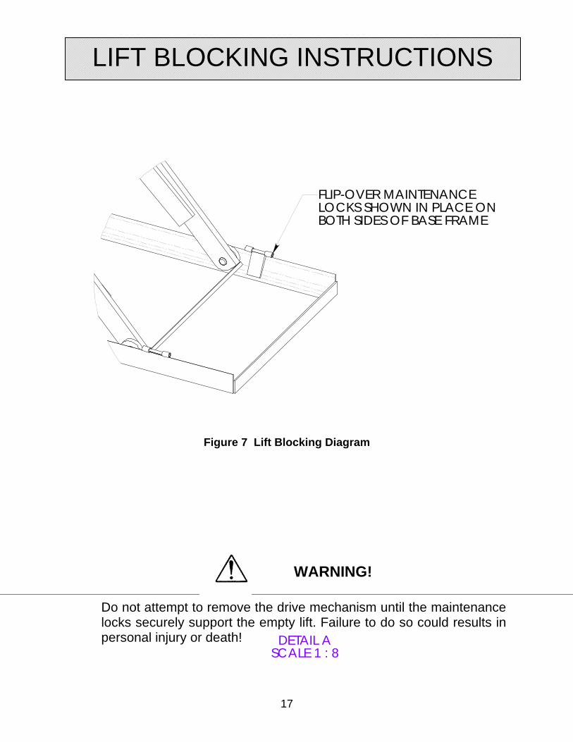
3. Locate all hinged maintenance locks permanently welded outside the base frame on the roller end of the lift base legs. Both locks must be flipped over and resting inside the base frame and thus in the roller path of the lift (See Figure 7). If both left and right maintenance locks are not fully engaged the lift could fall unexpectedly, resulting in permanent damage to the devices or the lift.
LIFT BLOCKING INSTRUCTIONS
17
DETAIL ASCALE 1 : 8
FLIP-OVER MAINTENANCE LOCKS SHOWN IN PLACE ON BOTH SIDES OF BASE FRAME
Figure 7 Lift Blocking Diagram
WARNING!
Do not attempt to remove the drive mechanism until the maintenance locks securely support the empty lift. Failure to do so could results in personal injury or death!
LIFT BLOCKING INSTRUCTIONS

18
DANGER !
If for any reason you are unable to lower the lift completely onto the maintenance device(s), stop immediately and consult the factory. Failure to properly use the factory approved maintenance device(s) could result in severe injury or death.
4. Once the maintenance devices are properly and securely engaged, be careful
to jog the DOWN button until the rollers are just touching the maintenance devices. To over-travel could cause damage to the mechanical drive system.
DANGER !
Over-travel or Under-travel of mechanical lifts could cause permanent damage to the lift system and cause the load to shift unexpectedly and potentially result in severe injury or death.
6. Follow OSHA electrical lock-out/tag-out procedures. Disconnect and tag all
electrical and/or other power sources to prevent an unplanned or unexpected actuation of the lift.
7. Once inspection or work is complete, reverse the performance of the steps
above to raise the lift off the maintenance devices and flip the devices back into their designated storage positions outside the base frame.
DANGER !
HIGH VOLTAGE!! – Disconnect and/or lock out the electrical supply to the power unit per OSHA regulations prior to any installation or maintenance being performed.
LIFT BLOCKING INSTRUCTIONS
19
WARNING!
Before installing the lift, read & follow the recommended safety practices in the Safety Practices section. Failure to follow these safety practices could result in death or serious injury
LIFT INSTALLATION 1. Make sure installation area is clean before starting. 2. If the permanent electrical work is not complete, some means of temporary lines with
an on-off device for the power supply should be set up for testing purposes. 3. Place the lift in the installation area.
NOTICE
When moving the lift do not attempt to pick it up by the platform; it is hinged and could be damaged. Pick up from under the base frame ONLY.
4. Make temporary electrical connections. Raise the lift to the top of its travel and
make positioning adjustments. Check for the proper height. If needed, shim to the desired height. DO NOT “spot” shim. Shim the full length of the base frame. This will prevent the frame from sagging under an exceptionally heavy load.
DANGER!
Do not work under the lift without Maintenance Device! To avoid personal injury, NEVER go under the lift platform until the load is removed and the scissors mechanism is securely blocked in the open position and the appropriate OSHA lock-out/tag-out procedure is followed . See "Lift Blocking Instructions" section.
INSTALLATION INSTRUCTIONS
20
5. The foundation for the unit must be rigid enough to maintain correct alignment with connected machinery and have ample strength to carry the maximum load.
6. The foundation should have a flat mounting surface to uniformly support the lift.
7. The base frame of the lift has pre-drilled holes for lagging the lift to the floor. Mark the holes, drill, and install with the appropriately sized anchors. Anchor bolts should be S.A.E. Grade 5 or equivalent.
PIT INSTALLATION -- MODELS WITH BEVEL TOE GUARDS
DANGER!
Do not install the lift in a pit unless it has a bevel toe guard or other approved toe protection. A shear point can exist which can cause severe injury to the foot.
1. Check the pit dimensions. Length and width should be 2" minimum longer and
wider than the lift platform. Depth should include ½” allowance for shims or grout. 2. Check the chase entrance into the pit. The diameter should be 3". If the
permanent electrical work is not complete, some means of temporary lines with an on-off device for the motor should be set up for testing purposes.
3. Lower the lift into the pit and check for proper height. The lift should be solid and
flush with the pit angle framing.
BALL SCREW INSTALLATION
1. Be certain that the rating of the ball screw exceeds the maximum load that may be imposed upon it.
2. Ball Screws are typically shipped with grease in the unit. However, before operating any unit remove the housing plug and check the condition of the lubricant. See “Routine Maintenance” Section for lubrication instructions.
3. It is extremely important that the ball screw be installed so that the lifting screw is exactly plumb and that all connecting shafting is aligned with the worm shaft.
4. After precise alignment, each member must be securely bolted and, if possible, doweled in place. Doweling will assure exact repositioning if ever removed.
INSTALLATION INSTRUCTIONS

21
5. In the case of rotating units it is essential, for proper alignment and prevention of screw failure, that the load be attached to the traveling nut only when the load is in the position of travel closest to the ball screw housing.
6. Take up evenly on mounting bolts to avoid damaging the housing.
7. After the ball screw, miter boxes, couplings, etc. are installed and aligned, there should be no signs of binding or misalignment.
8. Shaft coupling guards are the responsibility of the customer and are not provided by Nook Industries unless specifically quoted to and ordered by the customer.
9. Caution must be taken when operating your ball screw mechanism at either extreme of travel. If possible, hard external stops should be provided.
10. If operating at the upper limits of the unit rating, DO NOT STOP the travel of the unit by running the lifting screw attachments or the load against the housing without providing switches for control of the motor.
DANGER !
Over-travel or Under-travel of mechanical lifts could cause permanent damage to the lift system and cause the load to shift unexpectedly and potentially result in severe injury or death.
10. Some means should be taken to secure the load while installing or removing the ball screw mechanism.
NOTICE Limit switches should be set by carefully moving to the set
position by hand or jogging. Care must be taken to avoid running lifting screws out of units or crushing boots.
INSTALLATION INSTRUCTIONS

22
WARNING!
Familiarize yourself with this manual before operating this equipment.
1. Mechanical actuators have a maximum lifting capacity (see “Specifications” section).
Lifting loads exceeding the rated capacity of the lift may result in excessive wear and damage to the actuator or equipment structure.
2. This lift is designed for in-plant applications and is typically furnished with constant
pressure pushbutton controls. Normally, actuating the "UP" button – or providing some other “UP” command – will energize the lift actuator and cause the lift to rise.
3. When the desired height or upward travel of the platform is attained, removing the
operator’s finger from the “UP” button will cause upward movement to stop. The motor brake holds the lift in position. Upper travel limit switches are also common ways to automatically stop the lift at a pre-determined raised height.
WARNING !
Personnel should always maintain a safe operating distance of at least 36” any time the lift is operated up or down.
4. To lower the lift, activate the "DOWN" button or some other “DOWN” command,
which reverses the lift actuator motor and causes the lift to lower. 5. When the desired height or downward travel of the platform is attained, removing
the operator’s finger from the “DOWN” button will cause downward movement to stop. Lower travel limit switches are also common ways to automatically stop the lift at a pre-determined lowered height.
NOTICE
Do not continue to press a button if the lift is not raising or if it has reached the fully raised position. To do so may result in permanent damage to the lift.
OPERATING INSTRUCTIONS
23
NOTICE
In the absence of internal or external stops, it is possible to run the lifting screw out of the unit.
WARNING!
NEVER stand, sit or ride on the lift!
OPERATING INSTRUCTIONS
24
DANGER!
Before maintaining the lift, read & follow the recommended safety practices in the Safety Practices section. Failure to follow these safety practices could result in death or serious injury.
Normally mechanical lifts will require very basic maintenance to provide trouble-free operation. However, a routine maintenance program could prevent costly replacement of parts and/or downtime.
DANGER!
Do not work under the lift without a Maintenance Device! To avoid personal injury, NEVER go under the lift platform until the load is removed and the scissors mechanism is securely blocked in the open position and the appropriate OSHA lock-out/tag-out procedure is followed . See "Lift Blocking Instructions" section.
MONTHLY INSPECTION 1. Check all components for signs of noise, vibration, erratic movement, and any
other abnormal behavior. 2. Check overall condition of unit (i.e. bends, breaks, loose or missing bolts, etc.). 3. Check all wiring for looseness or wear. Repair at once. 4. Bearings on the drive should be greased; tighten all set screws 5. Inspect ball screw nut for wear or damage. 6. Inspect upper and lower travel sensing switches for proper operation; adjust as
required. 7. Check the condition of the lubricant in the gear box housing. Lubricant should be
flush with the bottom threads of the appropriate check plug. 8. Check for visible leaks at the housing; correct as necessary. 9. Check the snap rings at all lift rollers, if not in place and/or secure, replace or repair
immediately. 10. Check all rollers for signs of wear. Replace as necessary. (Do not grease roller or
axle bearings, they have lifetime-lubricated bearings).
ROUTINE MAINTENANCE
25
LUBRICATION – Gear Box Enclosure
Ball Screws are typically shipped with grease in the unit. However, before operating any unit remove the housing plug and check the condition of the lubricant.
1. Each ball screw unit is furnished with a grease fitting and a pipe plug on opposite sides of the housing. Remove the pipe plug.
2. Fill unit with grease until lubricant seeps from the pipe plug opening. 3. Replace pipe plug. 4. Lubricate upper bearing through grease fitting.
NOTE: The lubricant should not be corrosive to gears, ball or roller bearings and must be neutral in reaction. The lubricant must not contain any grit or dirt, abrasives or fillers. It should not precipitate sediment, nor separate at temperatures up to 300 Deg F. The lubricant must also have resistance to oxidation and must be non-channeling.
We recommend the following extreme pressure greases or equivalents. For operating conditions outside these limits consult factory.
COMPANY TRADE NAME TEMPERATURE RANGE *Exxon Nebulla EP#1 0 to 300Deg F Mobil Mobilux EP#1 20 to 225 Deg F Arco Litholine EP#1 20 to 200 Deg F Gulf Gulf Crown EP#1 0 to 250 Deg F Shell Aeroshell #22 85 to 400 Deg F *Calcium base. All others Lithium base. LUBRICATION – Ball Screw Assembly In the normal operating range (32 to 160 Deg F), oil or a good grade of light bearing grease may be used. Grease containing graphite or moly-disulfide should not be used. Use only enough lubricant to maintain a thin, continuous film. All units are suitable for intermittent operation in ambient temperatures up to 200 Deg F with proper grease. If protective boots are used, the material must be able to withstand the environment.
ROUTINE MAINTENANCE

26
WARNING!
Before maintaining the lift, read & follow the recommended safety practices in the Safety Practices section. Failure to follow these safety practices could result in death or serious injury.
WARNING!
Do not attempt to remove the motor brake or drive mechanism until the maintenance locks securely support the empty lift. Failure to do so could results in personal injury or death!
ACTUATOR REMOVAL AND REPLACEMENT 1. Securely block open the lift - see the "Lift Blocking Instructions”. 2. Always shut off the main electrical switch, when blocked, to prevent someone from turning it
on. 3. Be sure disassembly area is relatively clean to prevent contamination of parts. Store all
machined parts on wooden blocks or skids to prevent damage to machined surfaces. 4. When removing end caps, be sure to tape shaft extension keyways and other sharp edges
to avoid damaging oil seals.
NOTES: A. Be sure to clean and dry all parts before rebuilding. B. It is advisable to replace old seals when the unit is rebuilt. C. Remove any protective coatings on replacement parts before installing. D. On units equipped with Tapered Roller bearings, removal of the bearings from the drive
sleeve may result in their being damaged.
These instructions are necessarily general, and as such, cannot provide for minor details of construction, which may vary from unit to unit. For specific questions, consult equipment provider.
GENERAL MAINTENANCE

27
Figure 8 Exploded View of a Typical Assembly
GENERAL MAINTENANCE

28
Figure 9 – Cut-Away of a Ball Nut Assembly
Model 1 /2 - 100 BSJ - Upright or Inverted
1. Unscrew lifting screw cover assembly from unit. 2. Remove protective boot and end attachment from lifting screw, if applicable.
WARNING! Make certain lifting screw does not unscrew from ball nut. Use of heavy tape around lifting screw at each end of the nut will prevent this from happening.
3. Remove (2) socket head set screws locking housing extension. Unscrew extension from Jac.
4. On 20 and 30 BSJ units, remove (2) socket head set screws holding housing adapter (Item 18) to housing.
5. On 20-BSJ unscrew housing adapter. 6. On 30-BSJ screw housing adapter flush with the housing so that set screws
locking ball nut to drive sleeve may be removed. Unscrew ball nut from drive sleeve and remove ball nut and screw. Unscrew housing adapter from housing.
7. Remove end caps (Item 3) on worm shaft assembly.
NOTICE
Handle shims carefully to avoid damage
GENERAL MAINTENANCE

29
8. While tapping one end of the worm shaft with a wooden mallet, turn the worm shaft. This will loosen the bearing cup to facilitate removal.
9. Remove the worm shaft bearing cups. 10. Drive sleeve and gear, along with the ball nut and lifting screw, can now be
removed from the housing. 11. Further disassembly is possible by removing set screws from drive sleeve. 12. For ball nut disassembly consult Nook.
Keyed Units - Disassembly
1. Unbolt lifting screw cover assembly from unit. 2. Remove pin on torque collar 3. Unscrew torque collar from lifting screw. 4. Remove set screw from locking housing extension. Unscrew extension from Jac. 5. On 20 and 30 BSJ units remove socket head set screws holding housing
adapter to housing. 6. On 20-BSJ unscrew housing adapter. 7. On 30-BSJ screw housing adapter in flush with the housing so that set screws
locking ball nut to drive sleeve may be removed. Unscrew ball nut from drive sleeve and remove ball nut and screw. Unscrew housing adapter from housing.
8. Remove end caps on worm shaft assembly.
NOTICE
Handle shims carefully to avoid damage
9. While tapping one end of worm shaft with a wooden mallet, turn the worm shaft. This will loosen the bearing cup to facilitate removal.
10. Remove the worm shaft bearing cups. 11. Drive sleeve and gear, along with the ball nut and lifting screw, can now be
removed from the housing. 12. Further disassembly is possible by removing set screws from drive sleeve. 13. For ball nut disassembly consult factory.
Rotating Units - Disassembly
1. Remove 2 set screws from housing cover. 2. Unscrew housing cover. 3. Remove end caps on worm shaft assembly.
NOTICE
Handle shims carefully to avoid damage
GENERAL MAINTENANCE
30
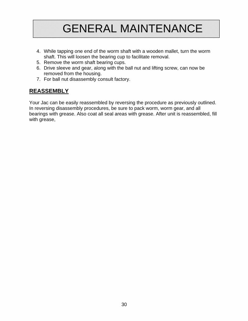
4. While tapping one end of the worm shaft with a wooden mallet, turn the worm shaft. This will loosen the bearing cup to facilitate removal.
5. Remove the worm shaft bearing cups. 6. Drive sleeve and gear, along with the ball nut and lifting screw, can now be
removed from the housing. 7. For ball nut disassembly consult factory.
REASSEMBLY
Your Jac can be easily reassembled by reversing the procedure as previously outlined. In reversing disassembly procedures, be sure to pack worm, worm gear, and all bearings with grease. Also coat all seal areas with grease. After unit is reassembled, fill with grease,
GENERAL MAINTENANCE
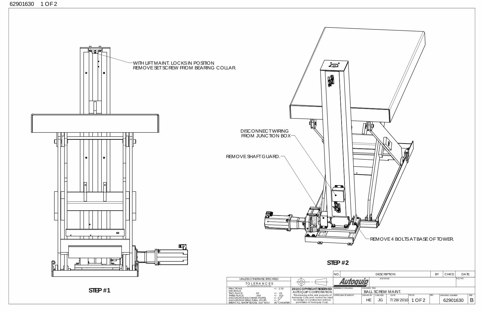
STEP #1
WITH LIFT MAINT. LOCKS IN POSITIONREMOVE SET SCREW FROM BEARING COLLAR.
REMOVE SHAFT GUARD.
REMOVE 4 BOLTS AT BASE OF TOWER.
DISCONNECT WIRING FROM JUNCTION BOX
HE
BALL SCREW MAINT.
7/28/2010JG
UNLESS OTHERWISE SPECIFIED: JOB NAME:
DRAWN BY: DATE: REV. SIZE:
DRAWING TITLE:
DRAWING NUMBER:PAGE:
AQJ NO:
REFERENCE DRAWING:
B629016301 OF 2APPROXIMATE WEIGHT:
62901630 1 OF 2
CHECKED:
ALL DIMENSIONS ARE IN INCHEST O L E R A N C E S
permission of Autoquip Corp.
ANGLES (FOR MACHINED PARTS) +/- 1/2ANGLES (FOR STRUCTURAL FIT-UP) +/- 1
CHAMFERBREAK ALL SHARP EDGES, .010" MAX 45
FRACTIONS: +/- 1/16DECIMALS:TWO PLACE: .XX +/- .03THREE PLACE: .XXX +/- .010
COPYRIGHT RESERVEDAUTOQUIP CORPORATION
This drawing is the sole property ofAutoquip Corp,and cannot be used
for design or construction without
2010
STEP #2NO. DESCRIPTION BY CHK'D DATE
7/28/2010
BALL SCREW MAINT.
HE
JG
UNLESS OTHERWISE SPECIFIED: JOB NAME:
DRAWN BY: DATE: REV. SIZE:
DRAWING TITLE:
DRAWING NUMBER:PAGE:
AQJ NO:
REFERENCE DRAWING:
2 OF 2 62901630APPROXIMATE WEIGHT:
B
62901630 2 OF 2
CHECKED:
ALL DIMENSIONS ARE IN INCHEST O L E R A N C E S
permission of Autoquip Corp.
ANGLES (FOR MACHINED PARTS) +/- 1/2ANGLES (FOR STRUCTURAL FIT-UP) +/- 1
CHAMFERBREAK ALL SHARP EDGES, .010" MAX 45
FRACTIONS: +/- 1/16DECIMALS:TWO PLACE: .XX +/- .03THREE PLACE: .XXX +/- .010
COPYRIGHT RESERVEDAUTOQUIP CORPORATION
This drawing is the sole property ofAutoquip Corp,and cannot be used
for design or construction without
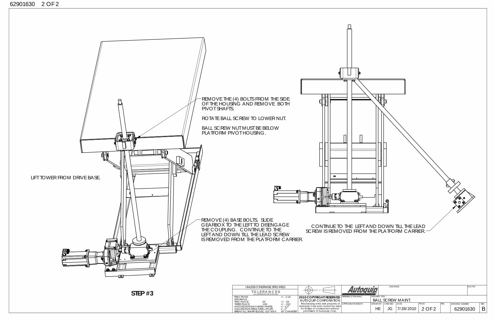
2010STEP #3
OF THE HOUSING AND REMOVE BOTHPIVOT SHAFTS.
ROTATE BALL SCREW TO LOWER NUT.
BALL SCREW NUT MUST BE BELOW PLATFORM PIVOT HOUSING.
LIFT TOWER FROM DRIVE BASE.
REMOVE THE (4) BOLTS FROM THE SIDE
REMOVE (4) BASE BOLTS. SLIDEGEARBOX TO THE LEFT TO DISENGAGETHE COUPLING. CONTINUE TO THE LEFT AND DOWN TILL THE LEAD SCREW IS REMOVED FROM THE PLATFORM CARRIER.
CONTINUE TO THE LEFT AND DOWN TILL THE LEAD SCREW IS REMOVED FROM THE PLATFORM CARRIER.
31
O.L
. RE
LAY
EL
EC
TR
ICA
L S
CH
EM
AT
IC
P.B
.
L3L2L1
L1L2
O.L
.F
OR
WA
RD
RE
VE
RS
EM
S 2
CO
NT
AC
TS
CO
NT
AC
TS
MS
1
7
(BY
OT
HE
RS
)
HE
AT
ER
S
CO
NT
AC
T
T1
T2
T3
FW
D.
RE
V.
MS
1
MS
2
60
CY
CLE
3 P
HA
SE
FU
SE
D D
ISC
ON
NE
CT
L2 L3L1
MO
TO
R:
60 C
YC
LE
3 P
HA
SE
XF
MR
.
TY
PIC
AL
PIL
OT
CO
NT
RO
LS
ON
LY
6/10
AM
P. F
US
E
1-6
/10
AM
P. F
US
E
15 H
OR
SE
PO
WE
R
46
0 V
OL
T
460V
.
46
0 V
OL
T
(BY
AU
TO
QU
IP)
TE
FC
25
4T
FR
AM
E
(BY
OT
HE
RS
)
RE
VE
RS
ING
MO
TO
R S
TA
RT
ER
"UP
"L.
SW
. L.S
W.
"DO
WN
"
11
5V.
2.
ALL
INT
ER
CO
NN
EC
TIN
G W
IRIN
G (
BY
OT
HE
RS
).
P.B
. = P
US
HB
UT
TO
N (
BY
OT
HE
RS
).
MS
1 &
MS
2 =
RE
VE
RS
ING
MO
TO
R S
TA
RT
ER
.
(BY
AU
TO
QU
IP).
XF
MR
. = T
RA
NS
FO
RM
ER
(B
Y A
UT
OQ
UIP
).
L.S
W. =
LIM
IT S
WIT
CH
ES
. "U
P"
AN
D "
DO
WN
"LI
MIT
SW
ITC
HE
S A
RE
MO
UN
TE
D A
ND
WIR
ED
BY
OT
HE
RS
.
MO
TO
R S
TA
RT
ER
W/O
VE
RL
OA
D R
EL
AY
AN
D 4
60
V/1
15V
EN
CLO
SU
RE
S.
ALL
OT
HE
R C
ON
TR
OLS
(B
Y O
TH
ER
S).
3. 4. 5. 6. 7.1.
FO
R U
SE
WIT
H P
US
HB
UT
TO
N.
SE
E A
Q D
WG
. #6
04
-01
38-0
D F
OR
LO
CA
TIO
N, E
TC
.
CO
NT
RO
L T
RA
NS
FO
RM
ER
, OP
EN
TY
PE
, TO
BE
SH
IPP
ED
TO
DO
OR
MA
N M
FG
. CO
. FO
R IN
ST
ALL
AT
ION
IN
NE
MA
12
1
45
6
33 3
3 33
22 2
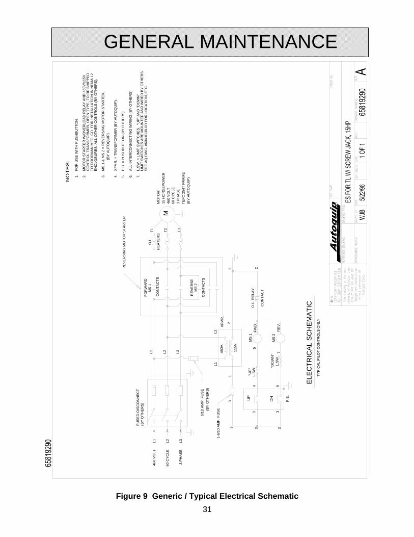
Figure 9 Generic / Typical Electrical Schematic
GENERAL MAINTENANCE

32
AQ PART # DESCRIPTION
28101030 LACT,50STK,10K,TRAV NUT
20016190 FLANGE BEARING,1BORE,4BOLT
34320790 PROXSW,TURCK, Bi 4‐M12‐RP6X‐H1143
34320800 CABLE, TURCK, WK 4T‐2
29500010 MTR,SERVO,AKM SERIES BRUSHLESS, W/INTERNATIONAL STD MOUNT,CLOSED KEWAY,MOTOR‐MOUNTED ROTATABLE INTERCONTEC
29500020 CNTRL FOR 29500010, COPELY CONTROLS DIGITAL BRUSH/BRUSHLESS AMPLIFER, 100‐240 VAC SINGLE OR 3 PHASE INPUT, 18 AMP CONTINOUS, 36 AMPS PEAK,
37004370 RED,GEAR,3.77:1,W/SERVOMOTOR ADAPTOR, 277 in‐lb MAX INPUT TORQUE
20000121 CPLG,LJOY 095,BORE=3/4 KWAY3/16‐3/32
20000145 CPLG,LJOY 095,BORE=1 KWAY=1/4X1/8
20000162 SPIDER,LJOY 095,BUNA N
REPLACEMENT PARTS LIST
33
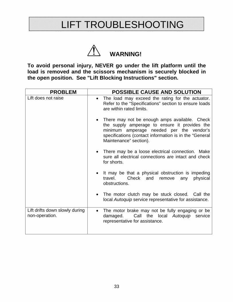
WARNING!
To avoid personal injury, NEVER go under the lift platform until the load is removed and the scissors mechanism is securely blocked in the open position. See "Lift Blocking Instructions" section.
PROBLEM POSSIBLE CAUSE AND SOLUTION Lift does not raise The load may exceed the rating for the actuator.
Refer to the “Specifications” section to ensure loads are within rated limits.
There may not be enough amps available. Check
the supply amperage to ensure it provides the minimum amperage needed per the vendor’s specifications (contact information is in the “General Maintenance” section).
There may be a loose electrical connection. Make
sure all electrical connections are intact and check for shorts.
It may be that a physical obstruction is impeding
travel. Check and remove any physical obstructions.
The motor clutch may be stuck closed. Call the
local Autoquip service representative for assistance.
Lift drifts down slowly during non-operation.
The motor brake may not be fully engaging or be damaged. Call the local Autoquip service representative for assistance.
LIFT TROUBLESHOOTING
34
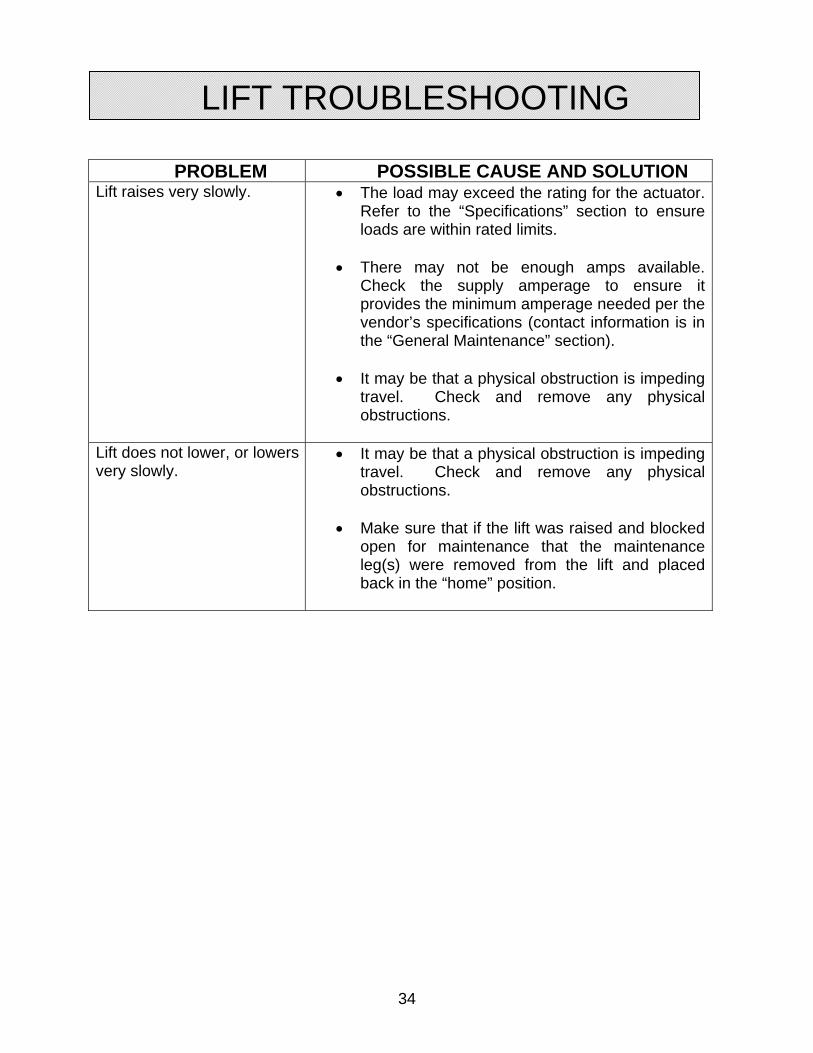
PROBLEM POSSIBLE CAUSE AND SOLUTION Lift raises very slowly. The load may exceed the rating for the actuator.
Refer to the “Specifications” section to ensure loads are within rated limits.
There may not be enough amps available.
Check the supply amperage to ensure it provides the minimum amperage needed per the vendor’s specifications (contact information is in the “General Maintenance” section).
It may be that a physical obstruction is impeding
travel. Check and remove any physical obstructions.
Lift does not lower, or lowers very slowly.
It may be that a physical obstruction is impeding travel. Check and remove any physical obstructions.
Make sure that if the lift was raised and blocked
open for maintenance that the maintenance leg(s) were removed from the lift and placed back in the “home” position.
LIFT TROUBLESHOOTING
35
ACTUATOR TROUBLESHOOTING
36
ACTUATOR TROUBLESHOOTING