vertical channel down mounting type vertical …feedwater heater are used in a regenerative steam...
TRANSCRIPT

FEEDWATER HEATER
122, Cheoyongsaneop 3-gil, Cheongnyang-myeon, Ulju-gun, Ulsan, 689-892, Korea
TEL : +82-52-237-2213 FAX : + 82-52-237-2235
E-mail : [email protected] Website : http://www.powerhx.com
De
sign
ed
by G
oo
d &
Go
od
De
sign
Co
mm
un
icatio
nsㅣ
20
16
. 11
.
www.powerhx.com
Vertical Channel Down Mounting type
Horizontal Mounting type
Vertical Channel Up Mounting type
TIE RODS AND SPACERS
TIE RODS AND SPACERS
U-TUBES
U-TUBES
U-TUBES
SHELL
SHELLTUBE SUPPORTS
TUBE SUPPORTS
TUBE SUPPORTS
DESUPERHEATING ZONE SHROUD
DESUPERHEATING ZONE SHROUD
DESUPERHEATING ZONE SHROUD
WATER LEVEL
WATER LEVEL
DESUPERHEATING ZONE BAFFLES
DESUPERHEATING ZONE BAFFLES
DESUPERHEATING ZONE BAFFLES
STEAM INLET
STEAM INLET
HEATER SUPPORT
HEATER SUPPORT
FEEDWATER OUTLET
FEEDWATER OUTLET
IMPINGEMENT BAFFLE
IMPINGEMENT BAFFLE
IMPINGEMENT BAFFLE
DRAIN INLET
DRAIN INLET
DRAIN INLET SHELL SKIRT
FEEDWATER OUTLET
STEAM INLET
HEATER SUPPORT
TIE RODS AND SPACERS
DRAIN OUTLET WATER LEVELPROTECTIVE SHIELD
FEEDWATER INLET
CHANNEL
DRAIN OULTET
DRAIN OULTET
CHANNEL
CHANNEL
FEEDWATER INLET
FEEDWATER INLET
DRAINS SUBCOOLING ZONE ENCLOSURE
DRAINS SUBCOOLING ZONE ENCLOSURE
OPTIONAL DRAINS SUBCOOLING ZONE
BY-PASS
OPTIONAL DRAINS SUBCOOLING ZONE BY-PASS
DRAINS SUBCOOLING ZONE BAFFLES
DRAINS SUBCOOLING ZONE BAFFLES
FEEDWATER HEATER
[ STEAM NOZZLE LOCATION- MULTIPLE INLETS ][ MINIMUM DISTANCE BETWEEN MULTIPLE STEAM NOZZLES ]
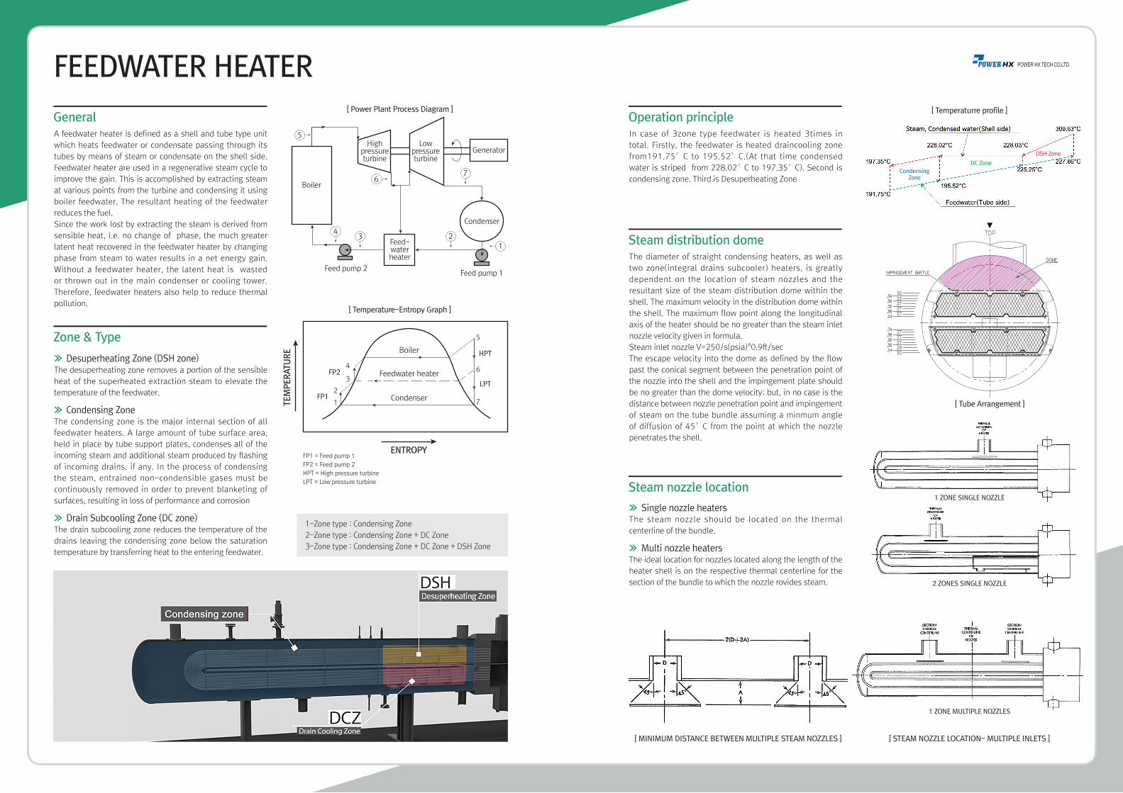
A feedwater heater is defined as a shell and tube type unit
which heats feedwater or condensate passing through its
tubes by means of steam or condensate on the shell side.
Feedwater heater are used in a regenerative steam cycle to
improve the gain. This is accomplished by extracting steam
at various points from the turbine and condensing it using
boiler feedwater. The resultant heating of the feedwater
reduces the fuel.
Since the work lost by extracting the steam is derived from
sensible heat, i.e. no change of phase, the much greater
latent heat recovered in the feedwater heater by changing
phase from steam to water results in a net energy gain.
Without a feedwater heater, the latent heat is wasted
or thrown out in the main condenser or cooling tower.
Therefore, feedwater heaters also help to reduce thermal
pollution.
General
>> Desuperheating Zone (DSH zone)The desuperheating zone removes a portion of the sensible
heat of the superheated extraction steam to elevate the
temperature of the feedwater.
>> Condensing Zone The condensing zone is the major internal section of all
feedwater heaters. A large amount of tube surface area,
held in place by tube support plates, condenses all of the
incoming steam and additional steam produced by flashing
of incoming drains, if any. In the process of condensing
the steam, entrained non-condensible gases must be
continuously removed in order to prevent blanketing of
surfaces, resulting in loss of performance and corrosion
>> Drain Subcooling Zone (DC zone) The drain subcooling zone reduces the temperature of the
drains leaving the condensing zone below the saturation
temperature by transferring heat to the entering feedwater.
Zone & Type
1-Zone type : Condensing Zone
2-Zone type : Condensing Zone + DC Zone
3-Zone type : Condensing Zone + DC Zone + DSH Zone
In case of 3zone type feedwater is heated 3times in
total. Firstly, the feedwater is heated draincooling zone
from191.75°C to 195.52°C.(At that time condensed
water is striped from 228.02°C to 197.35°C). Second is
condensing zone. Third is Desuperheating Zone
Operation principle
>> Single nozzle heatersThe steam nozzle should be located on the thermal
centerline of the bundle.
>> Multi nozzle heatersThe ideal location for nozzles located along the length of the
heater shell is on the respective thermal centerline for the
section of the bundle to which the nozzle rovides steam.
Steam nozzle location
The diameter of straight condensing heaters, as well as
two zone(integral drains subcooler) heaters, is greatly
dependent on the location of steam nozzles and the
resultant size of the steam distribution dome within the
shell. The maximum velocity in the distribution dome within
the shell. The maximum flow point along the longitudinal
axis of the heater should be no greater than the steam inlet
nozzle velocity given in formula.
Steam inlet nozzle V=250/s(psia)^0.9ft/sec
The escape velocity into the dome as defined by the flow
past the conical segment between the penetration point of
the nozzle into the shell and the impingement plate should
be no greater than the dome velocity; but, in no case is the
distance between nozzle penetration point and impingement
of steam on the tube bundle assuming a minmum angle
of diffusion of 45°C from the point at which the nozzle
penetrates the shell.
Steam distribution dome
[ Temperaturre profile ]
[ Tube Arrangement ]
1 ZONE SINGLE NOZZLE
2 ZONES SINGLE NOZZLE
1 ZONE MULTIPLE NOZZLES
CondensingZone
DC Zone
DSH Zone
[ Power Plant Process Diagram ]
[ Temperature-Entropy Graph ]