vertical configuration - · pdf fileactive receive antenna vertical configuration . arav3-1p...
TRANSCRIPT
- 1 -
Active Receive Antenna Vertical Configuration
. ARAV3-1P - Single Vertical Antenna
ARAV3-2P - Two Vertical Array Package (for use with NCC-1) ARAV3-4P - Four Vertical Array Package ARAV3-8P - Eight Vertical Array Package
(Export Models: ARAV3-1PE, ARAV3-2PE, ARAV3-4PE, ARAV3-8PE)
Used under US Patent No. 7,423,588
DXE-ARAV3-INS-Revision 3
© DX Engineering 2011
P.O. Box 1491 · Akron, OH 44309-1491 Phone: (800) 777-0703 · Tech Support and International: (330) 572-3200
Fax: (330) 572-3279 · E-mail: [email protected]

- 2 -
Table of Contents
Introduction 3 Location Considerations 3 General Information 4 Systems Packages 4
DXE-ARAV3-1P Single Active Receiver 4 DXE-ARAV3-2P Two Active Receivers 5 DXE-ARAV3-4P Four Active Receivers 5 DXE-ARAV3-8P Eight Active Receivers 5
Warning 5 Manual Updates 6 Features 6 Technical Description 6 Basic Tools Required 7 Installation 7
Location 7 Assembly 7 Ground Mounting Rod 9 Three Piece 102" Receiving Element - WP-102E 11 Providing a Good RF Ground 12 Connections 11 Coaxial Cable Feedline 13 Low Frequency Response - Internal Jumpers 13
Using the Active Receive Verticals in a 4 Square or 8 Circle Array 14 Alternate Mounting 15 Using the Active Receive Verticals with the DXE-NCC-1 16 Troubleshooting Information 16 Appendix A -Diagrams 17 Optional Items 22 Technical Support 24 Warranty 24

- 3 -
Introduction Ideal for Amateur Radio or Shortwave Listening, the DXE-ARAV3 Active Receive Antenna systems (ARAV3) offer excellent receiving performance from 100 kHz to 30 MHz using a whip antenna element only 102 inches long. DX Engineering’s unique design makes it vastly superior to traditional active antennas in both strong signal handling and feedline decoupling, providing significantly better weak signal reception due to lower spurious signal interference and reduced noise.
Location Considerations The best place to install your active antenna is where you have the recommended space away from power lines and away from your house, tower or any structures which are excellent sources of noise. Even passive wiring in a building or metal fencing can act as a pickup antenna and re-radiate of noise. The ARAV3 systems can be affected by local noise sources. Local noise can be random or directional in nature. Every effort must be made to locate sources of noise that could be eliminated at the source. Dimmer switches, electric timers, photocell-operated security lights, and many other items can be sources of unwanted noise. Plasma-screen television receivers are a known generator of unwanted noise interference. Most modern LED or LCD flat panel televisions are not broadband noise generators. If the noise source is external and single directional in nature, using two ARAV3 antennas in conjunction with the DXE-NCC-1 Receive Antenna Variable Phasing Controller could allow the user to phase out the noise being received. Large transmit antennas are a very good source of re-radiated noise. Ideally your receive antenna should be a minimum of 1/2-wavelength away from any transmit antenna (on the lowest frequency) to avoid mutual coupling and the transfer of any noise being re-radiated by the transmit antenna. If the unit is located 1/10-wavelength to 1/2-wavelength from a transmitting antenna, the unit must be powered off at least 5 ms before transmitting on the transmit antenna. However, with this close spacing, coupling from the nearby transmit antennas becomes more pronounced. At higher frequencies, where the active element length becomes a partial wavelength, coupling increases further. Placing a DXE-ARAV3 on the same mast or tower as a Yagi or other transmitting antenna is not recommended for this reason. To assure highest protection for the active antenna, a DXE-TVSU-1A Time Variable Sequencer Unit should be used to ensure the correct transmit-to-receive switching. The ARAV3 series active vertical antenna system grounds the antenna element when power is turned off.
THIS IS A RECEIVE-ONLY SYSTEM
You should never attempt to transmit through the system.
The use of bypass relays and sequential timing is required to avoid damage to the receiver and active antennas in the proximity of transmit antennas.
Placing any active receive system on the same mast or tower as the transmit antenna is not recommended.

- 4 -
General Information This compact receiving antenna system operates over a very wide bandwidth with superior strong signal performance. The output Third Order Intercept (TOI) is approximately +30 dBm. This is significantly better than most aftermarket preamplifiers and receivers - making it one of the cleanest active antennas on the market, reducing or eliminating spurious signals. Feedline decoupling, absent in some other popular designs, is also exceptionally good. Decoupling the shield greatly reduces feedline conducted noise and unwanted signal interference The ARAV3 systems can be affected by local noise sources. Local noise can be random or directional in nature. Every effort must be made to locate sources of noise that could be eliminated at the source. Dimmer switches, electric timers, photocell-operated security lights, and many other items can be sources of unwanted noise. If the noise source is directional in nature, using two ARAV3 antennas in conjunction with the DXE-NCC-1 Receive Antenna Variable Phasing Controller would allow the user to phase out the noise being received. Plasma-screen television receivers are a known generator of unwanted noise interference. Most modern LED or LCD flat panel televisions are not broadband noise generators. The DXE-ARAV3 active antennas may be used in installations when spacing from transmit antennas is at least 1/10-wavelength or more. Ideally your receive antenna should be a minimum of 1/2-wavelength away from any transmit antenna (on the lowest frequency) to avoid mutual coupling and the transfer of any noise being re-radiated by the transmit antenna. The DXE-ARAV3 series active vertical antenna system grounds the antenna element when power is turned off for protection of the active devices. When using active receive antenna radio systems with RF amplifiers a sequencer such as the DXE-TVSU-1A Time Variable Sequencer Unit should be used. This will ensure the correct timing while switching from receive to transmit, and back to receive, so the active receive antenna is protected from high energy fields from the transmit antenna. Systems Packages There are 4 Vertical Active Receive system packages. (DXE-ARAV3-1P, -2P, -4P, -8P)
Note: Export versions have a -E after the part number and contain the DXE-WP102E three piece antenna element rather than the one piece antenna element. The three section tapered stainless steel whip with machined couplers was designed to be compact in size for economical export shipping purposes.
DXE-ARAV3-1P
• Non-conductive mounting plate • Solid brass element mounting block • High quality, 102 in. tapered stainless steel whip antenna element • AVA-2 Active matching system w/ Internal Antenna Disconnect Relay • FVI-1 - Feedline Voltage Injector − powers the matching system and provides radio
connections • +12 Vdc wall mounted transformer (120 Vac 60 Hz in, +12 Vdc @ 500 mA out) • Stainless steel clamps and hardware

- 5 -
DXE-ARAV3-2P - The two active antennas system package DXE-ARAV3-2P is intended to be used with the optional DXE-NCC-1 Noise/Phase Controller to make a steerable dual vertical array. The NCC-1 can also provide power for the active antennas and the proper transmit power-off sequencing.
• (2) Non-conductive mounting plates • (2) Solid brass element mounting blocks • (2) High quality, 102 in. tapered stainless steel whip antenna elements • (2) AVA-2 Active matching systems w/ Internal Antenna Disconnect Relays • (2) Element connection wires • (2) Sets of Stainless steel clamps and hardware
DXE-ARAV3-4P - The four active antennas system package DXE-ARAV3-4P is intended for use with the optional DXE-RFS-3P Receive Four-Square system to build a Four-Square Receiving Array. The RFS-3P which has provision for powering the active antennas
• (4) Non-conductive mounting plates • (4) Solid brass element mounting blocks • (4) High quality, 102 in. tapered stainless steel whip antenna elements • (4) AVA-2 Active matching systems w/ Internal Antenna Disconnect Relays • (4) Element connection wires • (4) Sets of Stainless steel clamps and hardware
DXE-ARAV3-8P - The eight active antennas system package DXE-ARAV3-8P is intended for use with the optional DXE-RCA8-SYS-4P Receive Eight Circle system to build an Eight Circle Receiving Array. The RFS-3P which has provision for powering the active antennas
• (8) Non-conductive mounting plates • (8) Solid brass element mounting blocks • (8) High quality, 102 in. tapered stainless steel whip antenna elements • (8) AVA-2 Active matching systems w/ Internal Antenna Disconnect Relays • (8) Element connection wires • (8) Sets of Stainless steel clamps and hardware
The DXE-ARAV3 active antennas may be used in installations when spacing from transmit antennas is less than 1/2-wavelength but more than 1/10-wavelength (on the lowest frequency). The ARAV3 active vertical antenna grounds the antenna element when power is turned off. Ideally, receive antennas should be over 1/2 wavelength from transmit antennas. A DXE-TVSU-1A Time Variable Sequencer Unit should be used to ensure the correct transmit to receive switching. WARNING!
INSTALLATION OF ANY ANTENNA NEAR POWER LINES IS DANGEROUS

- 6 -
Warning: Do not locate the antenna near overhead power lines or other electric light or power circuits, or where it can come into contact with such circuits. When installing the antenna, take extreme care not to come into contact with such circuits, because they may cause serious injury or death. Manual Updates Every effort is made to supply the latest manual revision with each product. Occasionally a manual will be updated between the time your DX Engineering product is shipped and when you receive it. Please check the DX Engineering web site (www.DXEngineering.com) for the latest revision manual. Features
• Close Spacing from Transmit Antennas – Receive element is grounded at power-off • Sensitive − Weak signal sensitivity rivaling full size antennas • Wide Bandwidth – 100 kHz to 30 MHz • Excellent Strong Signal Handling − Outstanding Third Order Intercept of +30 dBm • Reduced Noise − Quiet FET followers and exceptional feedline shield isolation • Long Life − High quality stainless steel and brass mounting hardware, full metal
enclosure • Compact − Stainless steel tapered element has low visual and environmental impact • Easy Mounting and Installation Flexibility − Pre-drilled mounting plate and stainless
steel U-Bolt Saddle clamps for mounting to your 4 foot ground rod • May be connected to a transceiver which lacks a receive antenna input using the optional
DXE-RTR-1 Receive Antenna Interface for transceivers. Technical Description This compact receiving antenna system is designed to operate over a very wide bandwidth from the broadcast band to 30 MHz with superior strong signal performance. The Third Order Intercept (TOI) is approximately +30 dBm, reducing or eliminating spurious signals. Exceptional feedline decoupling, absent in some other popular designs, greatly reduces feedline conducted noise and unwanted signal interference. The DXE-ARAV3 Active Receive system requires well filtered +10 to +15 Vdc @ 60 mA nominal current. This power must be supplied through the feedline using the included DXE-FVI-1 Feedline Voltage Injector and wall mounted transformer power supply (also included). Alternatively, well filtered station power may be used with a 1 amp in-line fuse. If used, the DXE-TVSU-1A Time Variable Sequencer Unit or DXE-NCC-1 Receive Antenna Variable Phasing Controller will supply power for multi-element arrays. The DXE-TVSU-1A Time Variable Sequencer Unit and the DXE-NCC-1 Noise Canceling Receive Antenna Controller will interrupt the power to the DXE-ARAV3 for proper grounding during the transmit operation of the transceiver.

- 7 -
Basic Tools Required
• 5/16", 7/16", 1/2" wrenches or nut drivers, and a 5/8" wrench • # 2 Phillips Head Screw Driver
Installation Location The best place to install your active antenna is where you have the recommended space. The DXE-ARAV3 should be located a minimum of 1/2-wavelength (at the lowest frequency used) away from any transmit antenna. If the unit is located 1/10-wavelength to 1/2-wavelength from a transmitting antenna, the unit must be powered off at least 5 ms before transmitting on the transmit antenna. A sequencer such as the DXE-TVSU-1A should be used to ensure the correct transmit-to-receive switching. With this close spacing, coupling from nearby transmit antennas or metal structures becomes more pronounced. At higher frequencies, where the active element length becomes a partial wavelength, coupling increases further. Placing a DXE-ARAV3 on the same mast or tower as a Yagi or other transmitting antenna is not recommended for this reason. Assembly The assembly described is for the DXE-ARAV3-1P. Use DXE-81343 - Anti-Seize on stainless steel hardware threads to prevent galling and to ensure proper torque. Orient the black mounting plate with the two brass element mounting block holes closer to the top left, as shown in Figure 1. Use the 7/16" x 1-1/2" bolts, flat washers, split washers, and nuts to mount the brass element block to the mounting plate. Make sure the threaded hole in the element block for the antenna element is facing upward. Use a flat washer under each bolt head and a flat and split washer combination under each nut. Do not over-tighten.
Figure 1

- 8 -
Mount the AVA-2 matching unit with the ANT + terminal toward the top up. Use the 5/8" bolts, a flat washer under each bolt and a flat and split washer under each nut. Refer to Figure 2.
Figure 2
Loosely install the two stainless steel V-Clamps on the black mounting plate as shown in Figure 3. Figure 3 Upper Clamp Lower Clamp NOTE: The following describes the use of the DXE-SSVC-1P and DXE-SSVC-1PG V-Clamps
that are included with the ARAV3. These are used for mounting the ARAV3 on a typical ground rod from 1/2" OD to 3/4" OD.
If you plan to mount the ARAV3 to a larger mounting mast, you will need two optional
DXE-SSVC-150P and one optional DXE-SSVC-150PG V-Clamps which will accommodate a mounting pipe that is 1" OD to 1-1/2" OD. Refer to Figure 10 for examples.

- 9 -
Refer to Figure 4 and install one of the two wires (both are the same length) from the brass block to the AVA-2 antenna ANT + connection, use the wing nut and hand tighten only. The wire is held in place on the brass element block with one 5/16" x 1/2" bolt and one star washer. The closed lug goes on the brass element and the open lug goes on the AVA-2. Figure 4 The other wire goes from the ANT - (use the wing nut and hand tighten only) on the AVA-2 to the ground tab on the stainless steel V-Clamp installed on your ground rod as explained in the next section. The closed lug goes on the ground tab and the open lug goes on the AVA-2 as shown in Figures 5 and 6. Ground Mounting Rod Drive your four foot copper clad steel ground rod into the ground far enough to provide a sturdy mount for the antenna system. Ensure the ARAV3 unit will be above any potential standing water. Depending on soil conductivity, increasing ground rod depth beyond a few feet for an active receive antenna rarely improves RF grounding because skin effect in the soil prevents current from flowing deep in the soil. Avoid ground rods less than 5/8" in diameter. Position the ARAV3 unit on the ground rod adjust the height so the ground rod top is not higher than the ARAV3 black insulated panel. This prevents unwanted interference with the active element. Tighten the two V-Clamps to hold the ARAV3 in place. Attach the V-Clamp with the tab to the ground rod just below the bottom of the ARAV3 as shown in Figure 5. The V-Clamp can work with ground rods from 5/8" to 3/4" in diameter. Figure 5

- 10 -
Install the ground wire hardware and ground wire on the stainless steel V-Clamp with the tab. The other end of this wire goes to the AVA-2 ANT- connection as shown in Figure 6. Figure 6

- 11 -
Three Piece 102" Receiving Elements - WP-102E (Export version) The 102" Stainless Steel Tapered Receiving Element comes in two configurations. The ARAV3-1P has the single piece element and the ARAV3-1PE has the three piece element. The three piece antenna element was manufactured to take advantage of lower export shipping costs. Assembly is required for the three piece version. The base has the 3/8" thread mount for attaching to the ARAV3, there is a middle section, and the top section has a ball on the end (Figure 7). The sections are connected using the stainless steel couplers with hex Allen screws. Since the whip is tapered, there are two different sized couplers. The one with a stripe around the middle is drilled to fit the lower and middle sections together. The other connector has smaller holes for joining the middle to the upper section. Lower Coupler Upper Coupler (Stripe) Lower Section Middle Section Upper Section
Figure 7 - Three Section Stainless Steel Tapered Whip Antenna Once fitted together, use the supplied hex Allen wrench and firmly tighten the hex Allen screws.
Firmly install the 102 inch receiving element whip (one piece or three piece) in the top of the Brass Element Block.
After final testing and setting of jumpers (if needed, see pages 11 and 12 for jumper information) to enhance weather resistance, place a bead of non-corrosive, marine grade silicone along the seams where the two halves of the case meet. Leave small openings in the two bottom seams to allow any condensation to drain. Do not use sealants that have a vinegar-like smell because they contain acetic acid which will corrode aluminum. Recommended sealant is the DXE-RTV598335 - Approved RTV Sealant.
Rear View Front View

- 12 -
Providing a Good RF Ground This active vertical antenna works well with just a single copper ground rod used as the mounting rod. You can test ground quality by listening to a steady local signal. Attach 15 feet of wire laid in a straight line away from the coaxial feedline. If you observe a change in signal or noise level, you need to improve the ground. A second rod spaced a few feet away from, and connected to the first one may correct the problem. If a good ground cannot be established, use a DXE-RFCC-1 Feedline Current Choke that will further decouple the feedline from the antenna and reduce common mode current and associated noise from the feedline. If locate your ground mounted antenna where ground rods cannot be used effectively, you must use a radial system or metal ground screen. A suitable radial system consists of four to twelve equally spaced radials, with each radial being at least 15 feet long, but not longer than 20 feet. Only if the antenna is located over rock, on a roof, or otherwise installed where conductive soil conditions do not exist, you must use a ground screen. Welded-wire galvanized screens are okay for this receive antenna only and are not recommended for transmit antennas. Screen radius must at least equal the element height and be placed around the antenna as symmetrically as possible, but should not exceed a radius of 20 feet. The active receive vertical radial system should never be connected to any metal structure to assure low noise operation. Do not use elevated radials or grossly asymmetrical radial configurations. The ground system is an integral part of this receiving system, and if it is asymmetrical or exhibits pronounced resonances, the antenna system may not function properly. Connections For single antenna installations, the FVI-1 - Feedline Voltage Injector is installed near the operating position. When using the Active Receive Antenna, the FVI-1 powers the AVA-2 active antenna through its ANT+ feedline connection. See Figure 8. The feed line should be run away from the antenna at the exact center to the antenna element. If possible, bury the feed line for some distance from the antenna. This helps to decouple the feedline from unwanted noise. A DXE-RFCC-1 Receive Feedline Choke will also ensure feedline decoupling. Connect a suitable 75 Ω feedline to the type F connector OUTPUT. Leave a small loop in the feedline to relieve stress on the AVA-2 connection and securely attach the feedline to the mast below the mounting plate.
Figure 8 - Connections to the ARAV3 system using the FVI-1

- 13 -
The feedline connectors must remain dry. Do not place any intentional DC shorts or opens on the feedline between the FVI-1 and the AVA-2. This includes lightning arrestors, splitters, or any other accessory not intended for feedlines that carry power or control voltages.
The included DXE-PSW-12D1A 120 Vac 60 Hz, to 12 Vdc, 1000 mA wall mounted transformer DC power supply connects to the +12 Vdc input. The center of the 2.1mm power plug is positive. Larger power supplies or station power may also be used provided there is an in-line 1 ampere fast-blow fuse. The RCA phono-style plug on the DXE-FVI-1 connects to the receiver input of your radio.
The DXE-FVI-1 is not included or used in the ARAV3-2P or ARAV3-4P Vertical Array Packages which obtain their power from a controller unit such as the DXE-NCC-1 or DXE-RFS-3P. See Appendix A for Radio Interface Options Coaxial Cable Feedline Flooded 75 Ω CATV type feedline cable (F-6) is strongly recommended for use with the ARAV3 systems. DXE-F6 Flooded 75 Ω CATV type feedline cable has a bonded foil to improve shielding. Moisture typically seeps in around the shield and can cause increased noise. Flooded style cables have the distinct advantage of automatically sealing small accidental cuts or lacerations of the jacket. Flooded cable also prevents shield contamination and has a gummy liquid inside that seals cuts or nicks, displaces water, and can be direct buried. The feedline is used to provide power for the ARAV3's matching unit. We recommend the use of DXE-SNS6-25 Snap-N-Seal type F connectors to ensure high quality and weather resistant feedline connections. Use the proper tool to crimp these connectors. To help decouple the feedline from radiated noise, bury the feedline for some distance from the antenna when the feedline reaches the ground. A DXE-RFCC-1 DX Engineering Receive Feedline Choke will also ensure feedline decoupling, which may be installed in-line, preferably at the station end.
Low Frequency Response - Internal Jumpers The sensitivity response of the ARAV3 system does not need to be changed for most installations above 3.5 MHz. However, if you are interested primarily in frequencies below 3.5 MHz, jumpers may be required to optimize or increase sensitivity or eliminate interference from strong broadcast stations. Set the jumpers to the lowest operating frequency desired. Refer to Figure 9 for various jumper settings.

- 14 -
For access to the jumpers, loosen the two #2 Phillips Screws on each side of the AVA-2 unit and remove the chassis from the bottom. The circuit board and jumper headers will be visible as shown in Figure 9. The AVA-2 has five internal jumpers that modify frequency versus gain response. The L jumpers change the inductance values and C jumpers change the capacitance values. As shipped, all jumpers are deactivated. Figure 9 - Low Frequency Jumper locations & Settings Installing jumpers in L1MF, L1HF or both, will configure the antenna for a sensitivity peak near the frequencies listed in Figure 9. The frequency response above the peak frequency does not change significantly. Below the peak frequency, sensitivity reduction is reasonably fast. Installing a jumper in any C1 position when jumpers are being used in L1 will move the peak response lower in frequency, decreasing sensitivity at higher frequencies. Using the Active Receive Verticals in a 4 Square or 8 Circle Array Use the DX Engineering Receive Four Square System (DXE-RFS-3P) and four Active Receive Antennas (DXE-ARAV3-4P system package) to configure a four square vertical array. Power and receiver connections are provided through the RFS-3P system. Use the Receive Eight Circle system (DXE-RCA8-SYS-4P) and eight Active Receive Antennas (DXE-ARAV3-8P system package) to configure an eight circle receiving array. Power and receiver connections are provided through the RCA8-SYS system.

- 15 -
In a multi-element array, the internal jumpers are used to increase sensitivity at specific frequencies or to reduce interference from strong broadcast stations. When the ARAV3 is used in a DX Engineering DXE-RFS-3P Four Square Receiving Array or the DXE-RCA8-SYS-4P Receive Eight Circle System, select a jumper setting at least 5% below the frequency in use.
For Example: If operating at 1.80 MHz, multiply 1.80 times 0.95. That equals 1.71 MHz. Select jumper configurations no higher than 1.7 MHz.
In this example, referring to Figure 9, use jumper L1MF. Do not use C1 jumpers.
When four ARAV3 units are used in a four square array optimized for 160 meters and 80 meters, with 98 feet side lengths, the only jumper typically used is L1MF.
Configure all four ARAV3's units in the array with the same jumper settings.
The general rule is to use only L1 and not C1. For multi-band applications, use capacitors as a last resort. Capacitors peak the response and reduce sensitivity on higher bands. Figure 9 gives the approximate peak response frequency for various jumper settings using the vertically configured 102" whip antenna. Alternate Mounting If you plan to mount the ARAV3 to a larger mounting mast, two optional DXE-SSVC-150P and one optional DXE-SSVC-150PG V-Clamps are required which will accommodate mounting pipes from 1" OD to 1-1/2" OD. Refer to Figure 10 for examples.
Figure 10

- 16 -
Using the Active Receive Verticals with the DXE-NCC-1 ARAV3-2P Active Receive Vertical Antenna System (two ARAV3 Receivers) using a DX Engineering NCC-1 Noise Canceling Receive Antenna Controller. ARAV3 Active Receive Verticals must be at least 1/10-wavelength away from any transmit antenna. The NCC-1 switches the power off during transmit. This configuration allows the operator to selectively null out interference, and thereby enhance the desired received signal direction ability. Every radio manufacturer and every amateur radio operator's location is different. Refer to the DXE-NCC-1 manual for details. Also, you should consult your radio manufacturer's manual for details and further requirements. Troubleshooting Information When using the DXE-ARAV3-1P Active Receive Vertical antenna, the actual received signal level will be lower than a transmit antenna. Depending upon a few variables, including the frequency of the measured signal, your DXE-ARAV3-1P Active Receive Vertical is probably operating normally. The DXE-ARAV3-1P is designed to be a very low to no gain, low noise system for greatly improved signal-to-noise performance over a very wide range of frequencies. The installation location should be away from towers, transmitting antennas, metal structures and metal fencing in order to take advantage of the DXE-ARAV3-1P Active Receive Vertical antenna capabilities. Normally the Active Receive Vertical antenna will properly reject high angle sky wave signals, which is the goal for a low band DXing receive antenna. Low angle, long range DX signals are easier to copy using an Active Receive Vertical antenna system. Here are a few things that you may check to be sure that the Active Receive Vertical antenna is operating normally: 1) Measure the voltage arriving at the antenna end of the feedline. The DXE-FVI-1 Feedline
Voltage Injector unit should be providing in excess of +13.5 Vdc, and the Active is expecting around +11 Vdc or more for proper function. Bench tests on the DXE-ARAV3-1P are normally about 60 mA, so with some voltage drop on the line, 40 to 50 mA should be okay. If the measured voltage at the end of the line is under +11 Vdc, then there may be a resistive connection along the feedline being used. As a point of reference, DX Engineering has many customers using the DXE-F6-CTL/1000 high quality 75 Ω “flooded” F6 type coax. Flooded style cables have the distinct advantage of automatically sealing small accidental cuts or lacerations of the jacket. Flooding also prevents shield contamination and can be direct-buried. This low-loss cable features dual shields and an 85% Velocity Factor and is ideal for long runs on four and two antenna arrays without trouble.
2) Double check the jumpers inside the AVA-2 unit at the base of the Active Receive Vertical
antenna. As shown in the manual, for full range coverage, a default condition of no jumpers

- 17 -
installed should be found and used for broadcast band reception. If any jumpers are installed, you can expect signal levels to be dramatically reduced in the broadcast band. However, even with no jumpers, there is a significant roll-off of signal level from the top to the bottom of the broadcast band.
3) After tuning in a steady, non-fading reference signal on the broadcast band and noting the signal
level, add 4 radials that are about 15 feet long to the negative terminal ground rod connection on the AVA-2. If this significantly increases signal level, then adding another ground rod and/or more radials, as described in the manual for the DXE-ARAV3-1P, should improve your signal results for all bands.
4) When disconnecting the power to the Active Receive Vertical antenna, there should be very
little or no signal. In other words, verify that powering the Active Receive Vertical antenna results in improved signal level and signal-to-noise enhancement, without a large increase in noise. If there is almost the same amount of signal without and with power, there are two possible issues:
a) Proper operating voltage is not arriving at the Active Receive Vertical antenna, or; b) If you seem to have a high amount of common mode signal or noise arriving on the
shield of the Active Receive Vertical antenna feedline that is running on or above ground or similar noise as your transmit antenna, for some installations the DXE-RFCC-1 Receive Feedline Current Choke may help. The use of the DXE-RFCC-1 Receive Feedline Current Choke will remove common mode signal and noise collected by the shield of the feedline in order to realize normal signal-to-noise improvements available from an Active Receive Vertical antenna.
Given that all connections are good, voltage at the AVA-2 is good and that the other tests indicate everything is normal, it is likely the signal level you are receiving is normal. In most circumstances, the DXE-ARAV3-1P Active Receive Vertical antenna used singly, or in two and four antenna arrays, offers low level low band signals that have significantly improved signal-to-noise. It is sometimes necessary to enhance these results to listening levels by using the DXE-RPA-1 Receive Pre-Amplifier in line, without losing the signal-to-noise benefits of the no-gain Active Receive Vertical antenna. Only the DXE-RPA-1 Receive Pre-Amplifier operates with a third order intercept and dynamic range that is far superior to most receiver front-ends. Appendix A - Diagrams The following shows typical interface diagrams for the ARAV3-1P Active Receive Vertical Antenna System. Every radio manufacturer and every amateur radio operator's location is different. The following are only suggestions, and you should consult your radio manufacturer's manual for details and further requirements.

- 18 -
Shortwave Receiver: ARAV3-1P system located greater than 1/2-wavelength from any transmitting antenna, connected to a transceiver with a receive input.

- 19 -
DXE-ARAV3-2P Active Receive Vertical Antenna System (with two ARAV3 Receivers) using a DX Engineering DXE-NCC-1 Receive Antenna Variable Phasing Controller. ARAV3 Receivers must be at least 1/10-wavelength away from any transmit antenna and preferably more than 1/2-wavelength away. The NCC-1 switches the power off during transmit. This configuration allows the operator to selectively null out interference, and thereby enhance the desired received signal direction ability. Every radio manufacturer and every amateur radio operator's location is different. The following is only a suggestion, and you should consult your radio manufacturer's manual for details and further requirements.

- 20 -
Typical DXE-RFS-SYS-4P Receive Four Square System Configuration
Shown with optional items. Power connections not shown for clarity. Refer to the DXE-RFS-SYS-4P manual for details.
- 21 -
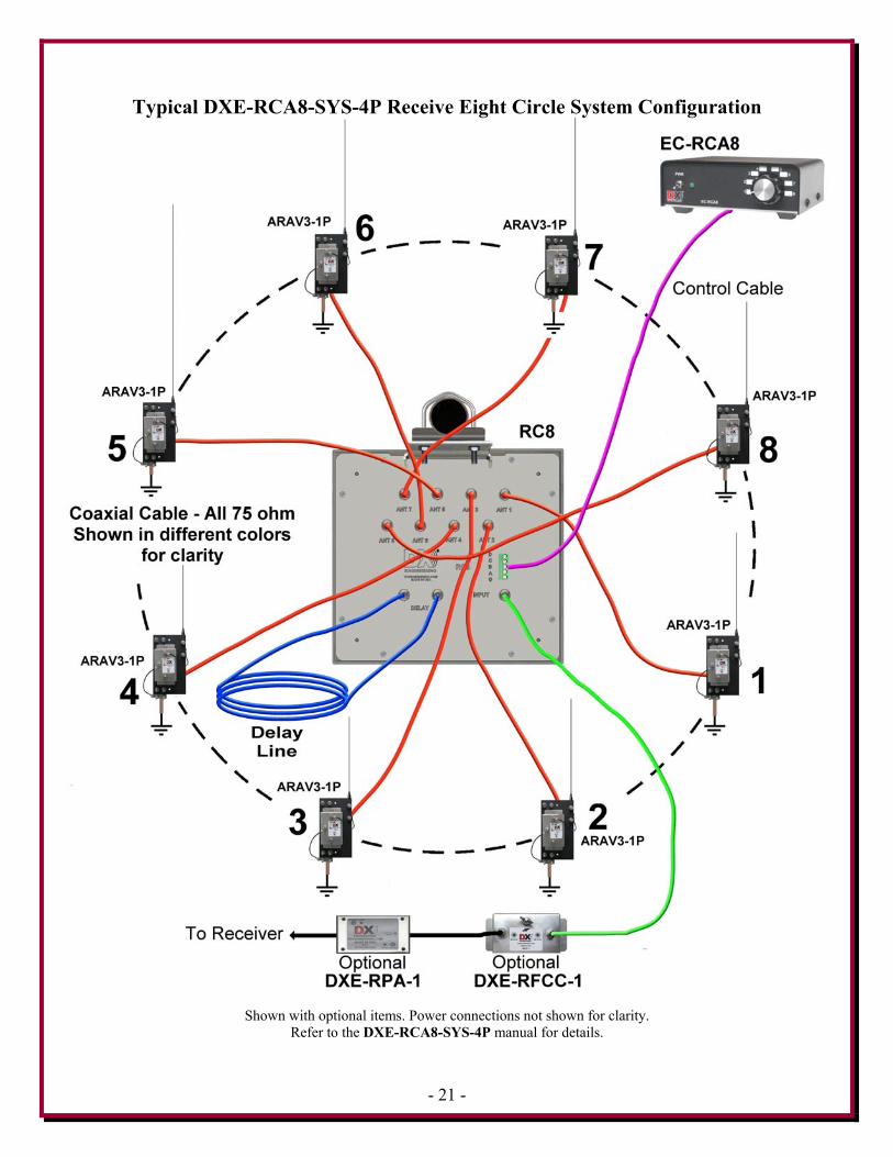
Typical DXE-RCA8-SYS-4P Receive Eight Circle System Configuration
Shown with optional items. Power connections not shown for clarity. Refer to the DXE-RCA8-SYS-4P manual for details.

- 22 -
Optional Items DXE-F6 - 75 Ω F-6 Style, Direct Bury Coaxial Cable: Full Spool or Custom Cable Assemblies DX Engineering recommends using a high quality 75 Ω “flooded” F6 type coaxial cable. Flooded style cables have the distinct advantage of automatically sealing small accidental cuts or lacerations of the jacket. Flooding also prevents shield contamination and can be direct-buried. This low-loss cable features dual shields and an 85% Velocity Factor. DXE-SNS6 Snap-N-Seal connectors are recommended for use with this coaxial cable to ensure a high quality and weather resistant feedline connection. The proper tool DXE-SNS-CT1 must be used to install these connectors. Custom cable assemblies are available, Call DX Engineering for details. DXE-CPT-659 - Coax Cable Stripper for CATV F-6, RG-6 and RG-59 coaxial cable. Coax Cable Stripper for CATV F-6, RG-6 and RG-59 coaxial cable. Includes 1 Replacement Blade - DXE-CPT-659. Prepares CATV F-6, RG-6 and RG-59 coaxial cable for the installation of "F" type connectors - One-step cutting motion
• Precision cut • No nicks or scratches to conductor
DXE-SNS6-25 - Watertight Coaxial Connector, Snap-N-Seal for CATV F-6 Cable, 25 pieces Snap-N-Seal is an environmentally sealed CATV F coaxial connector system for harsh environments. The connectors have a unique, 360 degree radial compression system that offers the signal leakage protection required for high performance receive systems.
• Quad sealed system prevents moisture from migrating into the connection • 360 degree radial compression provides superior RF integrity (-95dB typical, 60% bonded foil cable) • Easy cable preparation • Connector to cable retention of 40 lbs minimum • Superb impedance match to 1 GHz • Manufactured of high quality 360 brass, cadmium plated with yellow chromate coating for maximum
corrosion resistance • UV-resistant plastic and O-rings provide a reliable environmentally sealed connector
An installation tool, such as the DXE-SNS-CT1 is required to install the connectors. Normal crimping tools or pliers will not work. DXE-SNS-CT1 - Compression Tool for Snap-N-Seal 75 Ω Coaxial Connectors Ratchet compression tool for installing DXE-SNS6 Snap-N-Seal coaxial connectors. Ordinary pliers will not install these connectors properly.
DXE-SSVC-150P Stainless Steel V-Clamp This stainless steel V-Saddle Clamp is made in four sizes to fit steel tubing or pipe ranging from 1/2" to 3'' OD for use in antenna construction. The DXE-SSVC-150P uses a V-Bolt and will attach to a mast ranging in size from 1" OD to 1-1/2" OD. The V-Saddles is made from high-strength 304 (18-8) stainless steel. The special stainless steel saddles have serrated teeth and will clamp to the pipe securely by biting into the surface. For this reason, it is not recommended for softer aluminum tubing or pipe. Included are Stainless Steel Hex Nuts, Split Washers and Flat Washers. DXE-SSVC-150PG Stainless Steel V-Clamp with Tab This stainless steel V-Saddle Clamp is made in two sizes to fit steel tubing or pipe ranging from 1/2" to 1-1/2'' OD for use in antenna construction. The DXE-SSVC-150P uses a V-Bolt and will attach to a mast ranging in size from 1" OD to 1-1/2" OD. The V-Saddle is made from high-strength 304 (18-8) stainless steel. The special stainless steel saddles have serrated teeth and will clamp to the pipe securely by biting into the surface. For this reason, it is not recommended for softer aluminum tubing or pipe. Continuing on the popular DXE-SSVC series of clamps, the "G" models have a special tab for connecting an optional ground braid or wire. Included are Stainless Steel Hex Nuts, Split Washers, Star Washers, Hex bolt for the tab and Flat Washers.

- 23 -
DXE-NCC-1 - Receive Antenna Variable Phasing Controller Unlike conventional IF noise blankers, the NCC-1 is designed to reduce noise or interference before it gets to the receiver. The NCC-1 can be effective on all types of noise, including interference (QRM) from unwanted signals. The NCC-1 allows the user to continuously adjust both phase and amplitude when combining two antenna inputs. The signal output to the receiver is the addition or subtraction of signals from two separate antennas. Unwanted noise can be removed or unwanted signals can be cancelled. Desired signals can be peaked or enhanced. The NCC-1 generally works best when both antennas have similar patterns, polarization, and Signal-to-Noise ratios. For the most effective nulling of noise, both antennas must hear the same unwanted noise and should have similar polarization. The wanted and unwanted (QRM and QRN) signals must be arriving from different directions. Low noise active receive antennas such as the DXE-ARAV3-1P are extremely effective when used with the DXE-NCC-1. For an economical package of the DXE-NCC-1 and two DXE-ARAV3-1P antennas, see package number DXE-AAPS3-1P. Noise Nulling Receive Antenna Controller
• Reduce overload or interference by nulling a strong local signal or noise before it gets to your receiver • Better and more stable nulling than any other noise canceller on the market • Peak weak signals hidden under a strong signal on the same frequency • Null out local AM broadcast stations • Null out noise from power line arcing, lamp dimmers, motors and consumer electronics arriving from a single direction • Antenna Phasing Controller • Best alternative to DX Engineering's Receive Four-Square antenna • Combine two receiving antennas to create a directional pattern • The NCC-1 enables you to adjust the antenna array pattern as if you were moving the antennas • Use for direction finding

- 24 -
Technical Support If you have questions about this product, or if you experience difficulties during the installation, contact DX Engineering at (330) 572-3200. You can also e-mail us at:
For best service, please take a few minutes to review this manual before you call.
This unit is RoHS (Reduction of Hazardous Substances) compliant. The components, including the solder used are all lead free. If you decide to do any modifications or internal repairs, you should use only lead free solder and lead free soldering tools. Lead free solder melts approximately 100 degrees higher than the old leaded solder, so you may need to upgrade your current soldering system.
Warranty All products manufactured by DX Engineering are warranted to be free from defects in material and workmanship for a period of one (1) year from date of shipment. DX Engineering’s sole obligation under these warranties shall be to issue credit, repair or replace any item or part thereof which is proved to be other than as warranted; no allowance shall be made for any labor charges of Buyer for replacement of parts, adjustment or repairs, or any other work, unless such charges are authorized in advance by DX Engineering. If DX Engineering’s products are claimed to be defective in material or workmanship, DX Engineering shall, upon prompt notice thereof, issue shipping instructions for return to DX Engineering (transportation-charges prepaid by Buyer). Every such claim for breach of these warranties shall be deemed to be waived by Buyer unless made in writing. The above warranties shall not extend to any products or parts thereof which have been subjected to any misuse or neglect, damaged by accident, rendered defective by reason of improper installation, damaged from severe weather including floods, or abnormal environmental conditions such as prolonged exposure to corrosives or power surges, or by the performance of repairs or alterations outside of our plant, and shall not apply to any goods or parts thereof furnished by Buyer or acquired from others at Buyer’s specifications. In addition, DX Engineering’s warranties do not extend to other equipment and parts manufactured by others except to the extent of the original manufacturer’s warranty to DX Engineering. The obligations under the foregoing warranties are limited to the precise terms thereof. These warranties provide exclusive remedies, expressly in lieu of all other remedies including claims for special or consequential damages. SELLER NEITHER MAKES NOR ASSUMES ANY OTHER WARRANTY WHATSOEVER, WHETHER EXPRESS, STATUTORY, OR IMPLIED, INCLUDING WARRANTIES OF MERCHANTABILITY AND FITNESS, AND NO PERSON IS AUTHORIZED TO ASSUME FOR DX ENGINEERING ANY OBLIGATION OR LIABILITY NOT STRICTLY IN ACCORDANCE WITH THE FOREGOING. ©DX Engineering 2011 DX Engineering®, DXE®, DX Engineering, Inc.®, Hot Rodz™, Maxi-Core™, THUNDERBOLT™, Antenna Designer™, Yagi Mechanical™, and Gorilla Grip™ Stainless Steel Boom Clamps, are trademarks of PDS Electronics, Inc. No license to use or reproduce any of these trademarks or other trademarks is given or implied. All other brands and product names are the trademarks of their respective owners. Specifications subject to revision without notice.