vertical turbine pumps general...
TRANSCRIPT
VERTICAL TURBINE PUMPS
GENERAL INFORMATION
ww
w.v
ansa
n.co
m.tr
VERTICAL TURBINE PUMPSGENERAL INFORMATION

ww
w.v
ansa
n.co
m.tr
VERTICAL TURBINE PUMPSGENERAL INFORMATION
ABOUT US
Vansan was established at a 200 m² workshop in 1964 by Mech. Eng. A. Ozden ERTOZ and developed
rapidly on the path of becoming a global trademark by bringing together its expert engineering, importance
given on R&D activities and its customer-oriented working policy with its approximately 260 employees
working in 12000 m2 open and 8500 m2 closed area. Vansan achieves to export its products to 40
countries around the world.
www.vansan.com.tr
2 - 3

Powered by Engineering
Research and Development
Vansan R & D department uses a special design software already prepared by Vansan Engineers to create
a new impeller and diffuser. Design results will be rechecked by CFD programs before star ting the
preparation of patterns. This ability gives a great flexibility to create a new pump in a short period with
high efficiency.
High Efficiency
% 20 of produced energy in the world is consumed by pumps. Saving % 30 of this energy is possible with
a good system design and well designed pumps. With this awareness our purpose is to produce pumps
with high efficiencies up to %93. The most important criteria for Vansan Team is life cycle cost.
Different Material Option
Vansan gives a great material selection option to the customers for different applications such as cast
iron, cast steel, non-alloyed and low alloy steel grades, stainless CrNi Steel grades, duplex and
superduplex steel grades, Bronze, Ni-Al Bronze and others.
www.vansan.com.tr
4 - 5
Quality Assurance
Quality Control is a continuous process in Vansan. It star ts from the quotation phase, ordering phase,
manufacturing process, installation & operation phase, warranty period & after sales operations.
Performance test
Noise level testing
Vibration analysis
Liquid dye penetrant testing
Magnetic par ticle testing
Radiographic examination of welding
Ultrasonic examination of raw materials & weldings
Metallurgical analysis
Test capabilities:

Vansan has complete in house pattern shop powered by CAD-CAM programs. It gives a quick action
ability for the new designs and improvements.
www.vansan.com.tr
6 - 7
Thanks to the location of the factory, Vansan has a wide range of alternative foundries for different
materials.
Fabrication is made by qualified and certified welders who utilize M.I.G , T.I.G , and innershield welding
process.
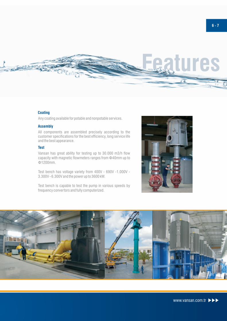
Any coating available for potable and nonpotable services.
All components are assembled precisely according to the customer specifications for the best efficiency, long service life and the best appearance.
Vansan has great ability for testing up to 30.000 m3/h flow capacity with magnetic flowmeters ranges from Φ40mm up to Φ1200mm.
Test bench has voltage variety from 400V - 690V -1.000V - 3.300V - 6.300V and the power up to 3600 kW.
Test bench is capable to test the pump in various speeds by frequency convertors and fully computerized.
CNC boring machines up to 2500mm diameter, Ver tical & Horizontal lathes and individual production
equipment supports an efficient and flexible manufacturing process.
Pattern Shop
Foundries
Welding Process
Coating
Assembly
Test
Machinery
Features
Vansan has complete in house pattern shop powered by CAD-CAM programs. It gives a quick action
ability for the new designs and improvements.
www.vansan.com.tr
6 - 7
Thanks to the location of the factory, Vansan has a wide range of alternative foundries for different
materials.
Fabrication is made by qualified and certified welders who utilize M.I.G , T.I.G , and innershield welding
process.
Any coating available for potable and nonpotable services.
All components are assembled precisely according to the customer specifications for the best efficiency, long service life and the best appearance.
Vansan has great ability for testing up to 30.000 m3/h flow capacity with magnetic flowmeters ranges from Φ40mm up to Φ1200mm.
Test bench has voltage variety from 400V - 690V -1.000V - 3.300V - 6.300V and the power up to 3600 kW.
Test bench is capable to test the pump in various speeds by frequency convertors and fully computerized.
CNC boring machines up to 2500mm diameter, Ver tical & Horizontal lathes and individual production
equipment supports an efficient and flexible manufacturing process.
Pattern Shop
Foundries
Welding Process
Coating
Assembly
Test
Machinery
Features

6
5
7
9
10
13
12
11
8
3
4
2
1
6
5
7
9
10
13
12
11
3
4
2
1
6
5
7
9
10
13
12
11
3
4
2
1
8
14
Wat
er L
ubri
cate
d Ve
rtic
al T
urbi
ne P
umps
Oil
Lubr
icat
edVe
rtic
al T
urbi
ne P
umps
Gre
ase
Lubr
icat
edVe
rtic
al T
urbi
ne P
umps
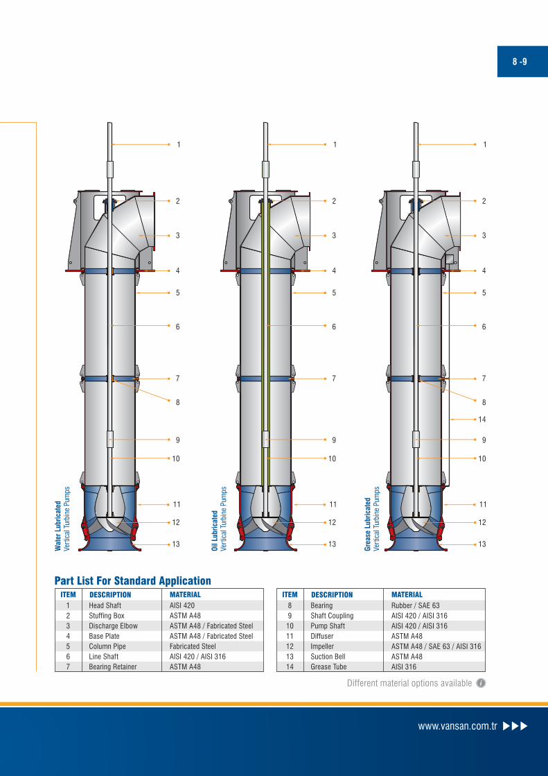
8 -9
ITEM DESCRIPTION MATERIAL
1
2
3
4
5
6
7
Head Shaft
Stuffing Box
Discharge Elbow
Base Plate
Column Pipe
Line Shaft
Bearing Retainer
Part List For Standard Application
AISI 420
ASTM A48
ASTM A48 / Fabricated Steel
ASTM A48 / Fabricated Steel
Fabricated Steel
AISI 420 / AISI 316
ASTM A48
ITEM DESCRIPTION MATERIAL
8
9
10
11
12
13
14
Bearing
Shaft Coupling
Pump Shaft
Diffuser
Impeller
Suction Bell
Grease Tube
Rubber / SAE 63
AISI 420 / AISI 316
AISI 420 / AISI 316
ASTM A48
ASTM A48 / SAE 63 / AISI 316
ASTM A48
AISI 316
SpecificationsPRODUCT PARTS FEATURES
Suction Bell
Impeller
Bowls
Shafts
Discharge Head
Each suction bell includes entrance guide vanes to
prevent prerotation while guiding the liquid flow parallel
to the drive shaft for maximum efficiency. Suction bells
can be fitted with strainers to restrict entry of foreign
objects during operation.
Impel lers, enclosed or semi-open, are prec ise ly
trimmed and balanced to reduce vibration and wear.
Impellers are secured firmly to the shaft by means of a
key and a split thrust ring or by a taper colled for small
pump sizes.
Bowl guide vanes are precisely designed for the
maximum conversion of kinetic enegy to the pressure
energy to achieve peak efficiency. The bowls are
flanged and the material selection is made according to
the pumping fluid. Bowls can be enamelled, plastic or
ceramic coated to reduce the friction losses and to
maintain a protective layer. Single or dual bronze and
r ubber bear ings prov ide a l l ignment and dampen
vibration. Bowls are supplied with a replaceable wear
rings.
The pump shaft is divided into three sections: head
shaft, line shaft and bowl shaft. Shafts are turned,
ground and polished and the material selection varies
depending on the application. The shaft is tailor made
to the service needs and sized individually for each
installation; calculated for maximum torque.
The d i scha rge head cons i s t s o f a su r f ace o r
underground sectional elbow. Heads are available in
high strength cast iron, fabricated steel or other
materials that are compatable to the pumped fluid.
Heads may be coated internally to fur ther resist
product corrosion. In addition efficiency improvement
NSF coatings for potable water are available.
Column Assembly
ShaftSeal
Drivers
Column pipes can be threaded or flanged according the
size and the customer request. Pipes are machined
between the centers to ensure perfect allignment. The
lubrication of the column assembly can be in threeways:
Oil Lubrication: Oil is supplied to bronze lineshaft
bearings by an oiler, secured on the motor base. Oiler
can be hand operated or solenoid for automatic
lubrication. Oil lubricated columns contain a lineshaft
enclosing tube. The suction bell bearing is packed with
water resistant grease, ensuring a long period operation.
Grease Lubrication: Grease is supplied to bronze
lineshaft bearings by a grease pump, secured the motor base .
Water Lubrication: The rubber lineshaft bearings are
lubricated by the pumped water. The suction bell bearing is
grease lubricated.
Options are provided for reliable sealing and simple
maintenance including gland packing and various mechanical
seal arrangements.
Ver tical electric motors are connected directly to the
pump. With hollow shaft motors, the pump downthrust
is carried by a thrust bearing built in the motor. The drive
shaf t extends up through the motor shaf t and is
properly secured at the top.
With solid shaft motors, the headshaft is connected to a
heavy oil lubricated ball bearing thrust assembly,
located on the pump base plate. If the thrust load is
more then the ball bearing assembly capacity then
tilting pad type bearings are located on the base plate.
Bearings are oversized to assure a minimum life of
40.000 hours operation.
Horizontal electr ic motors or internal combustion
engines are connected to the pump through suitable
right angle gear drive or belt drive.
Different material options available
www.vansan.com.tr
6
5
7
9
10
13
12
11
8
3
4
2
1
6
5
7
9
10
13
12
11
3
4
2
1
6
5
7
9
10
13
12
11
3
4
2
1
8
14
Wat
er L
ubri
cate
d Ve
rtic
al T
urbi
ne P
umps
Oil
Lubr
icat
edVe
rtic
al T
urbi
ne P
umps
Gre
ase
Lubr
icat
edVe
rtic
al T
urbi
ne P
umps
8 -9
ITEM DESCRIPTION MATERIAL
1
2
3
4
5
6
7
Head Shaft
Stuffing Box
Discharge Elbow
Base Plate
Column Pipe
Line Shaft
Bearing Retainer
Part List For Standard Application
AISI 420
ASTM A48
ASTM A48 / Fabricated Steel
ASTM A48 / Fabricated Steel
Fabricated Steel
AISI 420 / AISI 316
ASTM A48
ITEM DESCRIPTION MATERIAL
8
9
10
11
12
13
14
Bearing
Shaft Coupling
Pump Shaft
Diffuser
Impeller
Suction Bell
Grease Tube
Rubber / SAE 63
AISI 420 / AISI 316
AISI 420 / AISI 316
ASTM A48
ASTM A48 / SAE 63 / AISI 316
ASTM A48
AISI 316
SpecificationsPRODUCT PARTS FEATURES
Suction Bell
Impeller
Bowls
Shafts
Discharge Head
Each suction bell includes entrance guide vanes to
prevent prerotation while guiding the liquid flow parallel
to the drive shaft for maximum efficiency. Suction bells
can be fitted with strainers to restrict entry of foreign
objects during operation.
Impel lers, enclosed or semi-open, are prec ise ly
trimmed and balanced to reduce vibration and wear.
Impellers are secured firmly to the shaft by means of a
key and a split thrust ring or by a taper colled for small
pump sizes.
Bowl guide vanes are precisely designed for the
maximum conversion of kinetic enegy to the pressure
energy to achieve peak efficiency. The bowls are
flanged and the material selection is made according to
the pumping fluid. Bowls can be enamelled, plastic or
ceramic coated to reduce the friction losses and to
maintain a protective layer. Single or dual bronze and
r ubber bear ings prov ide a l l ignment and dampen
vibration. Bowls are supplied with a replaceable wear
rings.
The pump shaft is divided into three sections: head
shaft, line shaft and bowl shaft. Shafts are turned,
ground and polished and the material selection varies
depending on the application. The shaft is tailor made
to the service needs and sized individually for each
installation; calculated for maximum torque.
The d i scha rge head cons i s t s o f a su r f ace o r
underground sectional elbow. Heads are available in
high strength cast iron, fabricated steel or other
materials that are compatable to the pumped fluid.
Heads may be coated internally to fur ther resist
product corrosion. In addition efficiency improvement
NSF coatings for potable water are available.
Column Assembly
ShaftSeal
Drivers
Column pipes can be threaded or flanged according the
size and the customer request. Pipes are machined
between the centers to ensure perfect allignment. The
lubrication of the column assembly can be in threeways:
Oil Lubrication: Oil is supplied to bronze lineshaft
bearings by an oiler, secured on the motor base. Oiler
can be hand operated or solenoid for automatic
lubrication. Oil lubricated columns contain a lineshaft
enclosing tube. The suction bell bearing is packed with
water resistant grease, ensuring a long period operation.
Grease Lubrication: Grease is supplied to bronze
lineshaft bearings by a grease pump, secured the motor base .
Water Lubrication: The rubber lineshaft bearings are
lubricated by the pumped water. The suction bell bearing is
grease lubricated.
Options are provided for reliable sealing and simple
maintenance including gland packing and various mechanical
seal arrangements.
Ver tical electric motors are connected directly to the
pump. With hollow shaft motors, the pump downthrust
is carried by a thrust bearing built in the motor. The drive
shaf t extends up through the motor shaf t and is
properly secured at the top.
With solid shaft motors, the headshaft is connected to a
heavy oil lubricated ball bearing thrust assembly,
located on the pump base plate. If the thrust load is
more then the ball bearing assembly capacity then
tilting pad type bearings are located on the base plate.
Bearings are oversized to assure a minimum life of
40.000 hours operation.
Horizontal electr ic motors or internal combustion
engines are connected to the pump through suitable
right angle gear drive or belt drive.
Different material options available
www.vansan.com.tr

High PerformancePERFORMANCE RANGE
Vertical Flow Turbine Pumps
Q: 10 - 30.000 m³/h capacity & Head up to 600 m.
Water, oil & grease lubricated options
Axial Flow Turbine Pumps
Q: 900 - 20.000 m3/h capacity & Head up to 8 m.
Water, oil & grease lubricated options
Applications
Municipal water
Irrigation
Industrial
Power generation
Oil & Gas production
Mining
Storm water
Sump service
www.vansan.com.tr
10 - 11
60 Hz50 Hz
60 Hz50 Hz
Mixed Flow Vertical Turbine Pumps Performance Range
Axial Flow Vertical Turbine Pumps Performance Range
Tota
l Dyn
amic
Hea
d (m
)
10
0,1
100 1.000 10.000 100.000
1
Capacity (m³/h)
100
10
1
100 1.000 10.000 100.000 1.000.000
Capacity (gpm)
Tota
l Dyn
amic
Hea
d (f
eet)
1
10
100
1.000
10.000
1 10 100 1.000 10.000 100.000 1.000.00010 1001 1.000 10.000 100.000
1
10
100
1.000
Tota
l Dyn
amic
Hea
d (m
)
Tota
l Dyn
amic
Hea
d (f
eet)
Capacity (m³/h) Capacity (gpm)
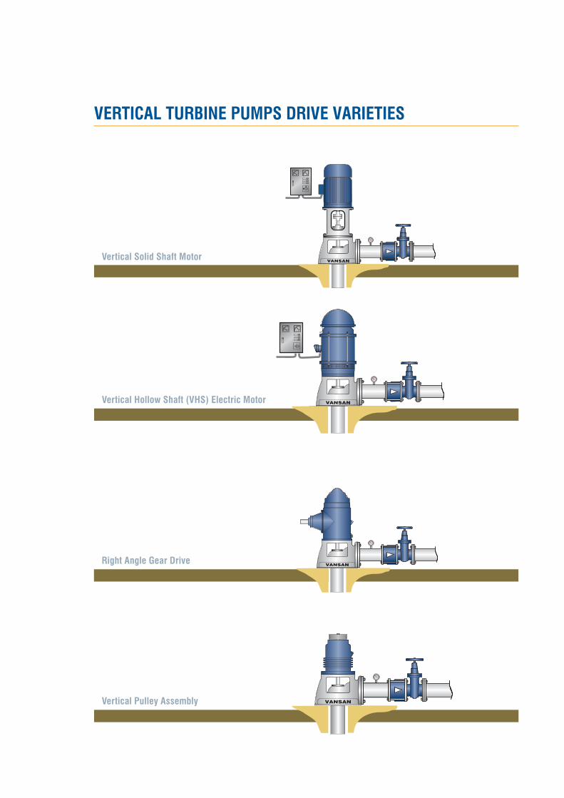
VERTICAL TURBINE PUMPS DRIVE VARIETIES
Vertical Solid Shaft Motor
VANSANVertical Pulley Assembly
VANSANRight Angle Gear Drive
0
1
VANSANVertical Hollow Shaft (VHS) Electric Motor
00
11
VANSAN
EN
GIN
EER
ING
Pow
ered
by

VERTICAL TURBINE PUMPS DRIVE VARIETIES
Vertical Solid Shaft Motor
VANSANVertical Pulley Assembly
VANSANRight Angle Gear Drive
0
1
VANSANVertical Hollow Shaft (VHS) Electric Motor
00
11
VANSAN
EN
GIN
EER
ING
Pow
ered
by

10035 Sk. No:10 A.O.S.B. 35620 - Cigli, Izmir / TURKEYT: +90 (232) 376 76 50 • F: +90 (232) 328 01 68
www.vansan.com.tr • [email protected]