vgrads: enabling e-science workflows on grids and clouds...
TRANSCRIPT

VGrADS: Enabling e-Science Workflows on Grids andClouds with Fault Tolerance
Lavanya RamakrishnanIndiana University,
Daniel NurmiUniversity of California, Santa
Anirban MandalRenaissance Computing
Charles KoelbelRice University
Dennis GannonMicrosoft Research
T. Mark HuangUniversity of Houston
Yang-Suk KeeOracle US Inc.
Graziano ObertelliUniversity of California, Santa
Kiran ThyagarajaRice University
Rich WolskiUniversity of California, Santa
Asim YarKhanUniversity of Tennessee,
Dmitrii ZagorodnovUniversity of California, Santa
ABSTRACTToday’s scientific workflows use distributed heterogeneousresourcesthrough diverse grid and cloud interfaces that are often hard toprogram. In addition, especially for time-sensitive critical appli-cations, predictable quality of service is necessary across these dis-tributed resources. VGrADS’ virtual grid execution system(vgES)provides an uniform qualitative resource abstraction overgrid andcloud systems. We apply vgES for scheduling a set of deadlinesensitive weather forecasting workflows. Specifically, this paper re-ports on our experiences with (1) virtualized reservationsfor batch-queue systems, (2) coordinated usage of TeraGrid (batch queue),Amazon EC2 (cloud), our own clusters (batch queue) and Euca-lyptus (cloud) resources, and (3) fault tolerance through automatedtask replication. The combined effect of these techniques was toenable a new workflow planning method to balance performance,reliability and cost considerations. The results point toward im-proved resource selection and execution management support for avariety of e-Science applications over grids and cloud systems.
1. INTRODUCTIONThe dream of providing on-demand computing resources for heavyusers has been discussed for over a decade under various names:grid computing [15], utility computing [36], cloud computing [28],and others. When the Virtual Grid Application Development Soft-ware (VGrADS) [25, 32, 51] project began in 2003, the state oftheart was a style of grid computing that allowed High Performance
Permission to make digital or hard copies of all or part of this work forpersonal or classroom use is granted without fee provided that copies are notmade or distributed for profit or commercial advantage, and that copies bearthis notice and the full citation on the first page. Copyrights for componentsof this work owned by others than ACM must be honored. Abstracting withcredit is permitted. To copy otherwise, to republish, to post on servers or toredistribute to lists, requires prior specific permission and/or a fee.SC09 November 14-20, 2009, Portland, Oregon, USA(c) 2009 ACM 978-1-60558-744-8/09/11É $10.00
Computing (HPC) applications to run on distributed clusters, butonly with careful tending. Applications needed low-level program-ming for managing heterogeneous resources, scheduling of compu-tation and data movement, fault tolerance, and performancetuning.VGrADS set out to raise the level of programming for grid appli-cations.
More recently, the rise of cloud computing has resulted in simi-lar concerns regarding application management and programmingmodels for scientific workflows. The cloud computing model pro-vides on-demand immediate access to virtual machines on a pay-as-you-go model. Cloud computing has evolved in support of Web2.0 applications [3] to manage dynamic load. Cloud computingfor scientific applications has certain trade-offs. Cloudsprovideimmediate guaranteed access to resources and customizablesoft-ware environments through virtual machines that overcome someof the challenges with current shared batch queue systems. How-ever, parallel scientific codes often experience a significant perfor-mance impact. Thus, we need programmatic methods for applica-tions to study the suitability of different resource environments andmake appropriate resource decisions.
We have made substantial progress in two broad areas of simplify-ing programming applications on grid and cloud systems :
• We separated application development from resource man-agement by providing a uniformvirtual grid abstraction atopwidely differing resources.
• We provided tools to efficiently bridge the abstraction gap,including methods for scheduling, resource management, dis-tributed launch, and fault tolerance.
Resource procurement and planning interfaces and strategies areespecially critical for time-sensitive applications. Mesoscale me-terology workflows in the Linked Environments for Atmospheric

ResourcesHPC
Globus EC2 interfaces
Workflow
Planner
Workflow
Engine
Application
Service
Portal
Virtual Grid
Execution System
ResourcesHPC
Globus EC2 interfaces
Execution
Manager
Workflow
Engine
Application
Service
Portal
Execution
Manager
resource
planning
resource
binding
query
execution
plan
standard
execution
specific protocol
based execution
UserUser
(b)(a)
Figure 1: Comparison of the LEAD-VGrADS collaboration system with cyberinfrastructure production deployments.
Discovery (LEAD) [10] project are examples of such deadline-sensitive workflows. These workflows are initialized by streamingsensor data and consist of a number of preprocessing steps that feeddata to a computation-intensive weather model. These workflowsrequire timely and coordinated access to computation and data dur-ing workflow execution.
This paper brings together many of the results from the VGrADSproject demonstrating the effectiveness of virtual grids for schedul-ing LEAD workflows. In the process, it demonstrates a seamlessmerging of cloud and HPC resources in service of a scientific ap-plication. It also applies advanced scheduling techniquesfor bothperformance improvement and fault tolerance in a realisticcontext.
LEAD has been run as a distributed application since its inception,but VGrADS methods have opened new capabilities for resourcemanagement and adaptation in its execution. We present the moti-vation for the LEAD application and explain the effect of VGrADSon workflow scheduling in Section 2. We discuss VGrADS systemcomponents and the execution flow in Section 3. This describesthe virtual grid abstraction, including its unified management ofTeraGrid clusters and Amazon EC2 and Eucalyptus cloud sites,and our support for fault-tolerant scheduling workflows. Wede-tail our experiments in Section 4 that demonstrate the feasibilityof the virtual grid abstraction’s new capabilities for e-Science [46]workflows such as LEAD and show that the overhead of the systemis low. Finally, in Sections 5 and 6 we discuss related work andpresent our conclusions.
2. OVERVIEWWe use the LEAD cyberinfrastructure [10] as a testbed for VGrADSideas. It is a modern cyberinfrastructure, with many features —notably the use of distributed resources for workflow execution— common to other e-Science domains [46]. In addition, LEADworkflows are time sensitive making timely resource procurementcrucial. All this makes it an ideal choice to test the VGrADS in-frastructure. The lessons learned here are more widely applicableto other e-Science applications and workflows [37].
2.1 LEAD Workflow ExampleLEAD users access large-scale data, forecast models, and analysisand visualization tools for mesoscale meteorology througha por-tal interface. Using the portal interface, they compose, launch andmonitorworkflows, each of which consists of a set of tasks that pro-duce and/or consume data. The need for data to be produced beforeit is consumed creates dependencies between the tasks. Moreover,many LEAD experiments requireworkflow sets. Because of themany parameters in weather models and uncertainty in the input,computing an exact result is often impossible. In these cases theuser must often run the same model many times with different ini-tial parameters to manage the accuracy of the result. Workflowplanning in LEAD must support scheduling workflow sets with twocharacteristics: a deadlineD when all work must be completed,and a fractionF of workflows which must complete by that dead-line. The LEAD portal uses a workflow engine to manage the taskdependencies and execution of a workflow. That engine in turninvokes the corresponding application service that has knowledgeabout the application’s configuration and data.
For example, imagine a LEAD experiment to forecast severe storms.A workflow in this experiment might take as inputs streaming sen-sor data to be pre-processed and then used to launch an ensembleof weather models. Based on the application’s requirements, theexperiment might need to finish within three hours (i.e.,D = 3) toproduce timely forecasts, and require 15 of 20 models to complete(i.e.,F = 3/4) to have acceptable confidence. It would be the work-flow engine and application services’s job to schedule the tasks sothat those constraints are met.
2.2 Virtual Grid AbstractionFigure 1 shows a simplified view of LEAD cyberinfrastructure,both with and without VGrADS. Both versions support the sameuser interface to construct and submit workflows. However, thevirtual grid abstraction (described in detail in Section 3) enablesa more sophisticated and effective scheduling of the workflow setsusing the virtual grid abstraction. Originally (Figure 1(a)), the ap-plication services interacted directly with distributed sites usingspecific interfaces. This led to ad-hoc resource schedulingdeci-
Start Deadline D
A
B C
D
J
K
L
E
F HG I
Start Deadline D
Batch Queue
Cloud
A B C D
E F HG
J K L
I
WAIT
WAIT
WAIT
WAIT
WAIT
WAIT
WAIT
WAIT
WAIT
WAIT
(a)
Example Workflow Setneed F=2/3
(c)
Coordinated ScheduleWith VGrADS
(b)
Uncoordinated ScheduleWithout VGrADS
Batch Queue
Cloud
A B C D
E F HG I
WAIT
WAIT
J K L
WAIT E´ F´ G´ H´ I´
E F HG I
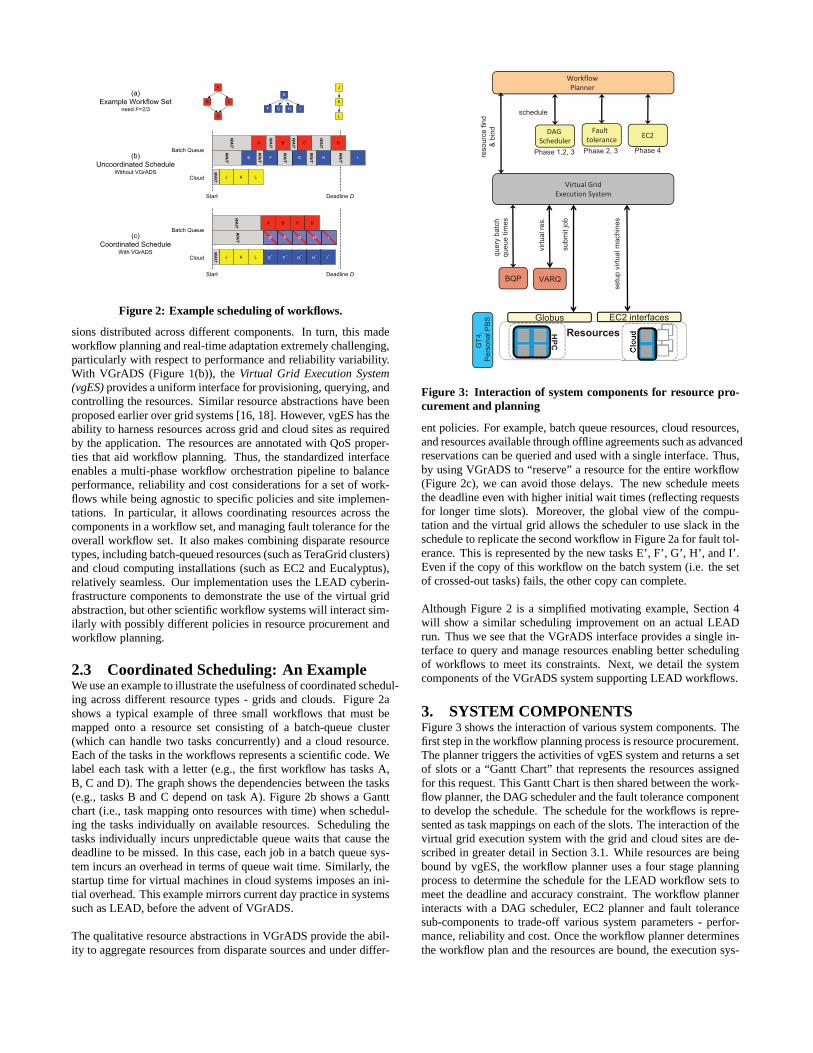
Figure 2: Example scheduling of workflows.
sions distributed across different components. In turn, this madeworkflow planning and real-time adaptation extremely challenging,particularly with respect to performance and reliability variability.With VGrADS (Figure 1(b)), theVirtual Grid Execution System(vgES)provides a uniform interface for provisioning, querying, andcontrolling the resources. Similar resource abstractionshave beenproposed earlier over grid systems [16, 18]. However, vgES has theability to harness resources across grid and cloud sites as requiredby the application. The resources are annotated with QoS proper-ties that aid workflow planning. Thus, the standardized interfaceenables a multi-phase workflow orchestration pipeline to balanceperformance, reliability and cost considerations for a setof work-flows while being agnostic to specific policies and site implemen-tations. In particular, it allows coordinating resources across thecomponents in a workflow set, and managing fault tolerance for theoverall workflow set. It also makes combining disparate resourcetypes, including batch-queued resources (such as TeraGridclusters)and cloud computing installations (such as EC2 and Eucalyptus),relatively seamless. Our implementation uses the LEAD cyberin-frastructure components to demonstrate the use of the virtual gridabstraction, but other scientific workflow systems will interact sim-ilarly with possibly different policies in resource procurement andworkflow planning.
2.3 Coordinated Scheduling: An ExampleWe use an example to illustrate the usefulness of coordinated schedul-ing across different resource types - grids and clouds. Figure 2ashows a typical example of three small workflows that must bemapped onto a resource set consisting of a batch-queue cluster(which can handle two tasks concurrently) and a cloud resource.Each of the tasks in the workflows represents a scientific code. Welabel each task with a letter (e.g., the first workflow has tasks A,B, C and D). The graph shows the dependencies between the tasks(e.g., tasks B and C depend on task A). Figure 2b shows a Ganttchart (i.e., task mapping onto resources with time) when schedul-ing the tasks individually on available resources. Scheduling thetasks individually incurs unpredictable queue waits that cause thedeadline to be missed. In this case, each job in a batch queue sys-tem incurs an overhead in terms of queue wait time. Similarly, thestartup time for virtual machines in cloud systems imposes an ini-tial overhead. This example mirrors current day practice insystemssuch as LEAD, before the advent of VGrADS.
The qualitative resource abstractions in VGrADS provide the abil-ity to aggregate resources from disparate sources and underdiffer-
schedule
reso
urc
e f
ind
& b
ind
Phase 1,2, 3 Phase 2, 3 Phase 4
BQP
GT
4,
Pe
rso
na
l P
BS
VARQ
ResourcesHPC
Globus EC2 interfaces
qu
ery
ba
tch
qu
eu
e t
ime
s
vir
tua
l re
s.
su
bm
it jo
b
se
tup
vir
tua
l m
ach
ine
s
Figure 3: Interaction of system components for resource pro-curement and planning
ent policies. For example, batch queue resources, cloud resources,and resources available through offline agreements such as advancedreservations can be queried and used with a single interface. Thus,by using VGrADS to “reserve” a resource for the entire workflow(Figure 2c), we can avoid those delays. The new schedule meetsthe deadline even with higher initial wait times (reflectingrequestsfor longer time slots). Moreover, the global view of the compu-tation and the virtual grid allows the scheduler to use slackin theschedule to replicate the second workflow in Figure 2a for fault tol-erance. This is represented by the new tasks E’, F’, G’, H’, and I’.Even if the copy of this workflow on the batch system (i.e. the setof crossed-out tasks) fails, the other copy can complete.
Although Figure 2 is a simplified motivating example, Section 4will show a similar scheduling improvement on an actual LEADrun. Thus we see that the VGrADS interface provides a single in-terface to query and manage resources enabling better schedulingof workflows to meet its constraints. Next, we detail the systemcomponents of the VGrADS system supporting LEAD workflows.
3. SYSTEM COMPONENTSFigure 3 shows the interaction of various system components. Thefirst step in the workflow planning process is resource procurement.The planner triggers the activities of vgES system and returns a setof slots or a “Gantt Chart” that represents the resources assignedfor this request. This Gantt Chart is then shared between thework-flow planner, the DAG scheduler and the fault tolerance componentto develop the schedule. The schedule for the workflows is repre-sented as task mappings on each of the slots. The interactionof thevirtual grid execution system with the grid and cloud sites are de-scribed in greater detail in Section 3.1. While resources are beingbound by vgES, the workflow planner uses a four stage planningprocess to determine the schedule for the LEAD workflow sets tomeet the deadline and accuracy constraint. The workflow plannerinteracts with a DAG scheduler, EC2 planner and fault tolerancesub-components to trade-off various system parameters - perfor-mance, reliability and cost. Once the workflow planner determinesthe workflow plan and the resources are bound, the execution sys-
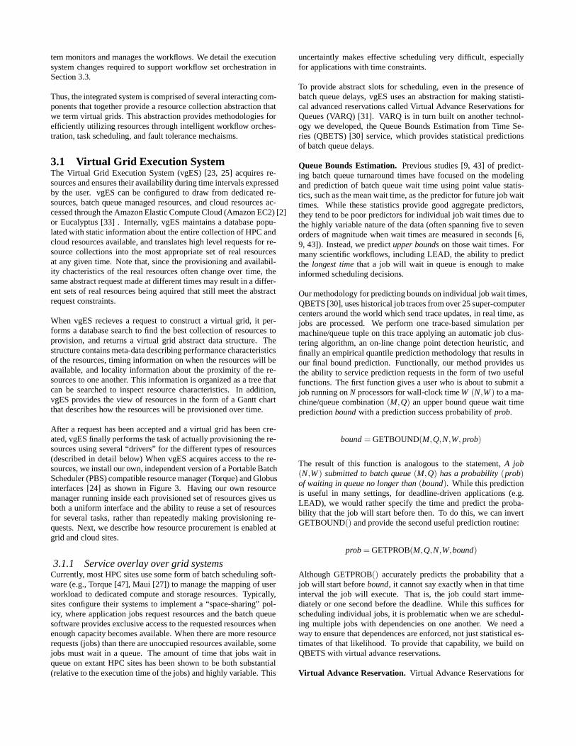
tem monitors and manages the workflows. We detail the executionsystem changes required to support workflow set orchestration inSection 3.3.
Thus, the integrated system is comprised of several interacting com-ponents that together provide a resource collection abstraction thatwe term virtual grids. This abstraction provides methodologies forefficiently utilizing resources through intelligent workflow orches-tration, task scheduling, and fault tolerance mechaisms.
3.1 Virtual Grid Execution SystemThe Virtual Grid Execution System (vgES) [23, 25] acquires re-sources and ensures their availability during time intervals expressedby the user. vgES can be configured to draw from dedicated re-sources, batch queue managed resources, and cloud resources ac-cessed through the Amazon Elastic Compute Cloud (Amazon EC2) [2]or Eucalyptus [33] . Internally, vgES maintains a database popu-lated with static information about the entire collection of HPC andcloud resources available, and translates high level requests for re-source collections into the most appropriate set of real resourcesat any given time. Note that, since the provisioning and availabil-ity chacteristics of the real resources often change over time, thesame abstract request made at different times may result in adiffer-ent sets of real resources being aquired that still meet the abstractrequest constraints.
When vgES recieves a request to construct a virtual grid, it per-forms a database search to find the best collection of resources toprovision, and returns a virtual grid abstract data structure. Thestructure contains meta-data describing performance characteristicsof the resources, timing information on when the resources will beavailable, and locality information about the proximity ofthe re-sources to one another. This information is organized as a tree thatcan be searched to inspect resource characteristics. In addition,vgES provides the view of resources in the form of a Gantt chartthat describes how the resources will be provisioned over time.
After a request has been accepted and a virtual grid has been cre-ated, vgES finally performs the task of actually provisioning the re-sources using several “drivers” for the different types of resources(described in detail below) When vgES acquires access to there-sources, we install our own, independent version of a Portable BatchScheduler (PBS) compatible resource manager (Torque) and Globusinterfaces [24] as shown in Figure 3. Having our own resourcemanager running inside each provisioned set of resources gives usboth a uniform interface and the ability to reuse a set of resourcesfor several tasks, rather than repeatedly making provisioning re-quests. Next, we describe how resource procurement is enabled atgrid and cloud sites.
3.1.1 Service overlay over grid systemsCurrently, most HPC sites use some form of batch scheduling soft-ware (e.g., Torque [47], Maui [27]) to manage the mapping of userworkload to dedicated compute and storage resources. Typically,sites configure their systems to implement a “space-sharing” pol-icy, where application jobs request resources and the batchqueuesoftware provides exclusive access to the requested resources whenenough capacity becomes available. When there are more resourcerequests (jobs) than there are unoccupied resources available, somejobs must wait in a queue. The amount of time that jobs wait inqueue on extant HPC sites has been shown to be both substantial(relative to the execution time of the jobs) and highly variable. This
uncertaintly makes effective scheduling very difficult, especiallyfor applications with time constraints.
To provide abstract slots for scheduling, even in the presence ofbatch queue delays, vgES uses an abstraction for making statisti-cal advanced reservations called Virtual Advance Reservations forQueues (VARQ) [31]. VARQ is in turn built on another technol-ogy we developed, the Queue Bounds Estimation from Time Se-ries (QBETS) [30] service, which provides statistical predictionsof batch queue delays.
Queue Bounds Estimation. Previous studies [9, 43] of predict-ing batch queue turnaround times have focused on the modelingand prediction of batch queue wait time using point value statis-tics, such as the mean wait time, as the predictor for future job waittimes. While these statistics provide good aggregate predictors,they tend to be poor predictors for individual job wait timesdue tothe highly variable nature of the data (often spanning five tosevenorders of magnitude when wait times are measured in seconds [6,9, 43]). Instead, we predictupper boundson those wait times. Formany scientific workflows, including LEAD, the ability to predictthe longest timethat a job will wait in queue is enough to makeinformed scheduling decisions.
Our methodology for predicting bounds on individual job wait times,QBETS [30], uses historical job traces from over 25 super-computercenters around the world which send trace updates, in real time, asjobs are processed. We perform one trace-based simulation permachine/queue tuple on this trace applying an automatic jobclus-tering algorithm, an on-line change point detection heuristic, andfinally an empirical quantile prediction methodology that results inour final bound prediction. Functionally, our method provides usthe ability to service prediction requests in the form of twousefulfunctions. The first function gives a user who is about to submit ajob running onN processors for wall-clock timeW (N,W) to a ma-chine/queue combination(M,Q) an upper bound queue wait timepredictionboundwith a prediction success probability ofprob.
bound= GETBOUND(M,Q,N,W, prob)
The result of this function is analogous to the statement,A job(N,W) submitted to batch queue(M,Q) has a probability(prob)of waiting in queue no longer than(bound). While this predictionis useful in many settings, for deadline-driven applications (e.g.LEAD), we would rather specify the time and predict the proba-bility that the job will start before then. To do this, we can invertGETBOUND() and provide the second useful prediction routine:
prob= GETPROB(M,Q,N,W,bound)
Although GETPROB() accurately predicts the probability that ajob will start beforebound, it cannot say exactly when in that timeinterval the job will execute. That is, the job could start imme-diately or one second before the deadline. While this suffices forscheduling individual jobs, it is problematic when we are schedul-ing multiple jobs with dependencies on one another. We need away to ensure that dependences are enforced, not just statistical es-timates of that likelihood. To provide that capability, we build onQBETS with virtual advance reservations.
Virtual Advance Reservation. Virtual Advance Reservations for
Queues (VARQ) [31] allows us to make probabilistic advance reser-vations with no modification to the underlying site softwareor poli-cies. Our studies of time series data gathered for QBETS showedus that, although the queue wait time experienced by jobs is highlyvariable, the upper bound predictions produced by QBETS arefarmore stable. Often, the predictions remain stable for days or weekschanging only when a drastic event occurs (e.g. a deadline for alarge user). Thus, we posit that we can legitimately make predic-tions for future job submissions assuming that large, prediction-changing events are infrequent. Based on this assumption, we havedevised a methodology that allows us to search the time betweennowand a specified future job start deadline to find the best time tosubmit a job to meet the deadline. VARQ computes aprobabilitytrajectory, in 30 second intervals, by repeated calls to the QBETSGETPROB() routine. At each interval, we know that the job couldstart immediately after being submitted, and so the execution timeof the jobW must be adjusted to cover the time to the deadline,plus the job runtime itself. We denote this adjusted job runtimeWad j. VARQ uses GETPROB() to obtain a probability prediction,decrementingboundandWad j by 30 seconds at each step until thedeadline is reached. At the end of this process, VARQ uses thecomputed probability trajectory and a specified minimum successprobability to find the latest point in time where a job can be sub-mitted so that it will start before the specified start time, holding theresources for the entire duration of the job after the deadline arrives.In a previous work [31] we showed that VARQ can successfullymake probabilistic advance reservations on large scale productionsuper-computers today. Using VARQ, vgES can time submission tothe queue to maximize the probability of resource arrival for virtualgrid use.
3.1.2 Cloud system overlayOver the past few years, a number of (mostly commercial) entitieshave started selling the excess capacity of their resourcesthroughan interface that allows a user to start and control virtual machineimages that are capable of running their applications. These “cloudcomputing” systems can provide substantial computing resourcesto scientists and other users. While the end product of many cloudsystems is similar to what a user expects to get from a batch sched-uled HPC resource, the way in which the resources are provisionedis very different, and has unique associated costs and benefits. Forexample, with Amazon’s EC2 [2], which is the leading cloud re-source provider, a user submits a request for a number of virtualmachine instances (based on a common template), and expectstoeither have those resources provisioned “instantly” (within a fewminutes) or for the request to fail. In batch queue systems, theexpectation is that a submitted valid job will always run “eventu-ally”. This difference adds a bit of complexity to a user who wouldlike to make advance allocation requests using both types ofre-sources in concert. In addition, another difference that impacts theco-scheduling of batch scheduled and cloud resources stemsfromthe fact that batch scheduled resources typically incur a cost that isvirtual in nature (users of such systems are commonly given abud-get of node/CPU hours that they “spend” when they use resources),where public cloud offerings such as Amazon EC2 charge usersbased on resource usage using real currency. Balancing these dif-ferent charging models during a resource scheduling phase must betaken into account and can be complex, depending on the objectivesof the user.
In vgES, we have built a “cloud resource” driver that has a similarinterface to the previously discussed QBETS/VARQ batch queuedriver. Since Amazon EC2 is currently the best specified and most
common interface to cloud resources, the driver is built to con-trol virtual machine reservations through the EC2 API. Using thisdriver, vgES may provision resources from EC2 in order to meetdeadlines if the current set of batch queue resources are unlikely tosatisfy a user request.
To further augment the number of resources available to users, wehave built an open source cloud computing system called Euca-lyptus [33] that can be run on any set of machines that supportscommonly available open-source software (Linux, Xen, etc). Euca-lyptus exports an EC2-compatible interface and therefore the vgESdriver can interact with any Eucalyptus installation just as it inter-acts with Amazon EC2. Thus, using Eucalyptus, we can transformany collection of machines into an EC2-compatible compute cloudthat can be seamlessly managed by vgES. Studies into the suitabil-ity of cloud computing systems for HPC application workloads [12,35] indicate that certain applications perform well in existing publicclouds while others require more specialized performance/featureenhancements before they become viable HPC resource providers.While the public clouds are generally designed to provide goodperformance for a wide variety of applications, we can leveragethe fact that Eucalyptus can run on local resources to provide thoseenhancements. The result for us is a specialized cloud computinginstallation that can utilize high performance networks, access tolocal parallel file systems, and other resources that are nottypicallyoffered by public cloud computing systems. We feel that thisisthe direction that private clouds and clouds for e-Science use willneed to take in the future. We further argue that these experimentssuggest that such clouds can be a viable platform for scientific com-putation.
3.2 Workflow PlannervgES interacts with different resource types and unifies resourcesavailable with certain properties to the workflow planner. For ex-ample, scientific workflows such as LEAD often have assigned al-locations through TeraGrid and other supercomputing centers aswell as other local cluster sites. In addition to these assigned re-sources, users might have access to other resources that might havehigher price points and are not used regularly. LEAD can use Ama-zon EC2 resources that are priced differently from the TeraGrid re-sources. The trade-off cost versus benefit of using higher pricedresources must be represented in the workflow planning process.Using vgES, we study the impact of scheduling LEAD workflowsets on a mix of TeraGrid, local grid and cloud sites and AmazonEC2 resources. This four phase workflow planning approach isde-tailed in this section.
The workflow planning approach we describe here specificallytar-gets deadline-sensitive workflows such as LEAD. However thedif-ferent phases of the workflow planning approach can be applied toother workflows which might be less time-sensitive.
3.2.1 Resource ProcurementEach resource site is queried for a certain number of processors forthe time duration from now till the deadline. Our workflow orches-tration has two goals: to meet the specified deadline and schedulethe maximum number of workflows in the given time such as to in-crease the probability that at least the minimum required workflowscomplete by the deadline. Thus, we pick an aggressive resourcerequest policy (with no cost constraints) querying all sites for themaximum duration. Once a minimal set of resources are available,the workflow planner instructs vgES to “bind” the resources (i.e.,appropriate mechanisms are used to start the procurement ofthe re-

sources on grid and cloud sites). Resource availability might be de-layed due to batch queue wait times or the virtual machine startupoverhead. Once resources become available vgES sets up appro-priate application software. The multi-phase planning process isinitiated in parallel.
3.2.2 Phase 1: Minimal SchedulingThe goal of this stage of the pipeline is to schedule the minimumfraction of workflows required on regular resource sites (i.e., wedo not use Amazon EC2 in this phase). We implement a sim-ple probabilistic DAG scheduler. The DAG scheduler traverses theDAG bottom-up and assigns deadlines for the tasks given a work-flow deadline. Subsequently the tasks are sorted by deadlineforthe scheduling phase. Each task T has a durationd and must bescheduled no earlier thanearliestStartTimeand must finish no laterthan latestFinishTime. The DAG scheduler finds a task mappingon each of the slots returned by vgES for a particular task. Subse-quently all task mappings that meet the task deadline are consideredfor selection and the best success probability mapping is selected.Data transfer times are accounted for when finding a task mappingthat can meet a deadline. For any task in a workflow, the probabilitythat it will succeed depends on the resource on which it is sched-uled as well as the probability of its parent tasks finishing.Whentwo tasks are scheduled on independent resource slots theirprob-abilities are independent and the probability of a task is the jointprobability of its parent and itself. However, in a slot abstraction,if a Task T and its parents are scheduled on the same resource slotthen the Task T has the same probability of finishing as its weakestparent. The process is repeated for all tasks in the workflow.If theminimum fraction of workflows cannot be scheduled at this stage,the planner exits with an error. The probability of a workflowcom-pleting is the minimum of the success probability of all tailnodes.
3.2.3 Phase 2: Fault Tolerance Trade-offIn the trade-off stage we compare scheduling additional workflowswith increasing the fault-tolerance of one or more tasks of the sched-uled minimum fraction of workflows. We compare the successprobability of the minimum fraction of workflows completingasthe criteria for picking the scheduling at this stage. Probabilitiesof tasks completing are computed using the failure probability ofthe resources and the probabilities of its parent tasks. We maintaina queue of tasks from the scheduled workflows that are sorted bytheir probability of completion. We compare:
1. a schedule from scheduling additional workflow from theworkflow set, and
2. a schedule where a taskTi from the sorted queue of tasksof the scheduled workflow from Phase 1 is replicated one ormore times on available resources.
The workflow planner interacts with a fault tolerance componentto determine if a task should implement replication in the secondcase. For this implementation, the fault tolerance component im-plements replication based fault-tolerance techniques toincreasethe probability of success for each workflow task. Given the cur-rent mapping of tasks on a Gantt chart of available resource slotswith corresponding reliability characteristics, each workflow task isreplicated on additional slots to increase the probabilityof successof a task to the desired success probability. This in turn increasesthe workflow success rate and hence potentially increases the frac-tion of workflows that need to finish by a given deadline.
The fault-tolerance techniques determine the mapping of the repli-cated tasks on the available slots and return the mapping to theplanner. During this mapping process, we use simple techniquesbased on joint-probabilities derived from success probabilities oftasks on slots. For each task, a window of replication is determinedby the planner, which constrains the replicated tasks to start-afterand end-before particular time based on task dependencies.Thefault tolerance mapping process tries to fit a task on the availableslots in that replication window based on the expected performancecharacteristics of the task (number of cpus required and expectedexecution times derived from performance models). If the task fitson a slot, the success probability of the task increases. When thesuccess probability reaches the desired level during this replicationprocess, the mapping of the replicated tasks is returned to the plan-ner. It should be noted that the fault tolerance techniques may notbe able to reach the desired success probability by replication in allcases. In such cases, the workflow planner is responsible forchang-ing system parameters (e.g. less compact Gantt chart, additionalresources) and iteratively using the fault tolerance techniques.
The schedule that yields the higher success probability from thesetwo approaches is selected and this step is repeated till no additionalworkflows can be scheduled or all tasks in the originalM workflowshave been checked to see if fault tolerance can be applied.
3.2.4 Phase 3: Additional SchedulingThe goal of this phase is to use the available space on the slots forany other scheduling. If any workflows in the set have not beenscheduled in the earlier step, an attempt is made to schedulethose.If any tasks have not been checked for fault tolerance in the ear-lier step, an attempt is made to replicate those tasks to increase itssuccess probability.
3.2.5 Phase 4: EC2 SchedulingFinally, the planner uses Amazon EC2 as a backup resource to de-termine if additional replication on this higher-priced resource canincrease the success probability of individual tasks. Amazon EC2is the prevailing example of cloud systems. The cloud model lendsitself well to adaptive load conditions albeit at a slightlyhigher costmodel. This makes it an ideal choice for using as a overflow re-source site for LEAD workflows to meet application requirements.
This orchestration approach enables us to study (a) the trade-offsbetween replicating certain tasks in the workflow, (b) the implica-tions of using Amazon EC2 as a overflow resource for scientificworkflows. We use specific policies (e.g., Amazon EC2 as over-flow resource) in this implementation but the multi-phase workflowplanning is configurable for other use cases and policy choices [40].
3.3 Execution ManagerWorkflow engines execute workflows based on DAG dependen-cies. However when considering workflow sets the execution planmight include execution dependencies on other workflow’s tasksthat might be scheduled to run on the same resources. Thus weneed execution level support for workflow set execution in slotsthat respects the order of the DAG and other workflow tasks sched-uled on the same slot.
We implemented a simple slot exection ordering mechanism intheExecution Manager (shown in Figure 1b). This ordering mecha-nism submits jobs to the slot execution batch queue system usingthe schedule. When the execution manager receives a job it checks

to see if all tasks that are scheduled on the slot before this task havebeen submitted. If not all tasks scheduled before this have beensubmitted the task is saved in a pending queue for later execution.Events in the system such as job submission and job completiontrigger a thread that checks the elements in the pending queue tosee if a task might now be ready to run. This ordering mechanismis sufficient to sequence task execution on slots as per the gener-ated schedule. However this ordering mechanism is not completelyresistant to failures. If an earlier task fails to arrive, a task will bestuck in the pending queue till it is rectified. Thus, the orderingmechanism depends on an external mechanism such as the moni-toring system to diagnose errors and rectify it.
4. EVALUATIONThe integrated system demonstrates a powerful resource abstrac-tion over grid and cloud systems that can be used by workflow plan-ning mechanisms for predictable service guarantees. This allowseven deadline-sensitive applications such as LEAD to run onnon-dedicated machines. However, it is important to understandthe dif-ferent parameters of the system and the tradeoffs with existing sys-tems. We present results that (a) demonstrate acceptable overheadof vgES in executing LEAD workflows on a distributed system(Section 4.1), (b) compare our approach to traditional approachesusing historical data from batch queue systems (Section 4.2), and(c) explore via simulation the parameters that impact the fault tol-erance (Section 4.3).
Workflows. We submit eight LEAD workflows which are ready torun in five minutes from the start of the experiment. The data set weuse for the each of the LEAD workflows is a small regional weatherforecast and takes about 90 minutes to complete. The first fewsteps of the workflow take a few minutes on single processors andthe weather forecasting model (WRF [29]) takes over an hour andfifteen minutes on 16 processors. The constraint on the workflowset is that at least one must complete by a deadline of 2 hours.Eachof the experiments was repeated between 10 to 15 times.
Testbed. The experiments in Sections 4.1 and 4.2 use the sametestbed containing batch and cloud resources. The softwarecon-sists of an Apache ODE workflow engine, the workflow plannerservice, the vgES code base and associated databases. The dis-tributed infrastructure consists of batch queue systems run at RENCI/ University of North Carolina Chapel Hill (kittyhawk), Universityof California Santa Barbara (mayhem), and NCSA TeraGrid (mer-cury); Eucalyptus-based cloud resources at University of Houston(uheuca), University of Tennessee Knoxville (utkeuca)), and Uni-versity of California Santa Barbara (ucsbeuca); and AmazonEC2(ec2). For this set of experiments we obtained advanced reserva-tions on the mercury and kittyhawk clusters.
Section 4.3 uses a different set-up. That testbed consists of a virtualmachine where our entire software stack is hosted. As we describein Section 4.3.1, the virtual machine allows us to vary system pa-rameters (e.g. reliability) to study their impact on fault tolerance..
Visual representation. All the experiments we describe began asdemonstrations at the SC08 conference. To give a feel for theex-periments, Figure 4 shows a screen shot from one run. (Full play-backs of several cases can be found on the web [48].) This runscheduled 5 of the 8 workflows distributed across the six resources.The slot on each resource is represented by a background greyrect-angle. Each colored rectangle represents one task, and tasks fromthe same workflow have the same color. Horizontal length repre-
sents (scheduled) time, and vertical height represents number ofprocessors (up to 32). The color bands at the bottoms of tasksrep-resent the task state (e.g. green for running, gray for completed).Here, the scheduler mapped many single-processor tasks from allthe workflows to utkeuca (a Eucalyptus cloud). It assigned theWRF models to the larger batch queue clusters (mayhem, kitty-hawk, and mercury). One model was replicated (on mercury andEC2) for fault tolerance. As it happened, one replica (on mercury,marked with the red band) did fail but the run met the overall con-straints.
4.1 Infrastructure timing metricsIn this section we study the performance of our integrated system.We present the event timeline of the system and compare the re-source binding parameters.
4.1.1 Resource Binding
0
5
10
15
20
25
ec2
kitty
haw
k
may
hem
mer
cury
ucsb
euca
uheu
ca
utke
uca
Dur
atio
n fo
r re
sour
ce b
indi
ng (
in M
ins)
Machines
Figure 5: Binding time
Figure 5 shows the average time required for binding each of thesites over nine to thirteen runs. The error bars show the minimumand the maximum values seen in the experiments. The batch sys-tems (kittyhawk, mayhem and mercury) take less time to set upthan the cloud sites in our setup since we have reservations in placeat the batch sites (kittyhawk and mercury) or the system has lowerloads (mayhem) and hence there is no wait time. The Eucalyptusclouds (uheuca, ucsbeuca, utkeuca) and Amazon EC2 grant accessto resources immediately but have a set-up overhead since the vir-tual machines need to be booted with the image. EC2 and uheucatake longer since they boot 16 nodes at each site. There is somevariation in the bind time at Amazon EC2, kittyhawk and mercurythat is the result of runtime characteristics such as the load on themachine. In this graph, we see that the overheads from cloud com-puting are slightly higher than from batch systems. Howevertheoverhead on all sites is less than 25 minutes, which is acceptablefor workflows such as LEAD which run for a number of hours.
4.1.2 Event timelineFigures 6 and 7 show a snapshot of an experiment timeline. Theseexperiments were repeated a number of times and are repeatable asshown in our archive [48]. Figure 6 shows the timeline of the plan-ning phase of the orchestration. Each line on the graph representsthe duration of a particular event where the ends of the line signifythe start and end time of the event. In the first step, the planner

Figure 4: Scheduling an actual LEAD workflow set using VGrADS.
queries vgES. Once a set of slots is determined to be sufficient, thebinding process starts on all the sites in parallel. While the bind-ing is in progress, the planner queries bandwidth across allpairs ofsites and launches the phased workflow planning. The four phasestake only a few seconds and complete well before the resourcepro-curement is complete. The resource procurement duration variesby site, but resources are ready within 20 minutes. Once the re-sources are ready, the workflows begin execution (Figure 7).Inthis snapshot workflow1 failed and hence finished early. All otherworkflows completed by the deadline of 2 hours as expected. Thesefigures demonstrate the effectiveness of our approach in schedulingworkflow sets across distributed resource sites.
We also compared the start and end times of execution with thosepredicted by the scheduler. The scheduler underestimated both by13 to 22 minutes. The cause of this is that the slots returned byvgES do not consider the overheads associated with resourcepro-curement and set-up. A simple work-around might be to assumea maximum overhead to the start time of the slots. But in the longterm, we need need better prediction mechanisms returned byvgESinterfaces, as well as support for dynamic and staggered executionto maximize slot utilization.
4.2 Deadline schedulingTable 1 compares our scheduler with other strategies for deadlinescheduling of workflows on a TeraGrid node. We use historicallogsfrom the batch systems to find average wait times for jobs similar tothe tasks in our workflow. In all cases, the queue variabilityis sig-nificant and strategies that do not appear to meet the deadlinemightwork at some times. For all the cases, “resource binding” is the de-lay to begin computing, whether it is due to waiting in a queueoroverhead for virtual machine startup. The best case time is runningwith an advanced reservation, thus avoiding any wait time. How-ever, this requires requesting the reservation far in advance, which
0
5
10
15
20
VG
ES
Que
ry
BIN
DIN
G-m
ayhe
m
BIN
DIN
G-k
ittyh
awk
BIN
DIN
G-m
ercu
ry
BIN
DIN
G-u
tkeu
ca
BIN
DIN
G-u
csbe
uca
BIN
DIN
G-e
c2
BIN
DIN
G-u
heuc
a
BA
ND
WID
TH
PH
AS
E1
PH
AS
E2
PH
AS
E3
PH
AS
E4
Tim
e (in
min
s)
Events
Figure 6: Time line of the planning phase of a run
is not always practical. Without reservations, current systems likeLEAD, insert tasks into a batch queue only when all their prede-cessors are complete (as Figure 2b showed). This incurs repeatedwaits in the queue, which the table shows to be more than the ac-tual execution time and causes the workflow to miss the deadline.Another strategy would be to submit a large job for an entire work-flow – corresponding to a virtual grid slot – which would run oneor more workflows. As the table shows, even submitting a singleworkflow in this way may not meet the deadline. In fairness, weshould note that, according to our data, this strategy wouldsucceedabout half the time based on the distribution of queue wait times.Requesting separate slots for six workflows (the number scheduledby our orchestration approach) is worse, and running all eight re-

0
20
40
60
80
100
120
wor
kflo
w1
(fai
led)
wor
kflo
w2
wor
kflo
w3
wor
kflo
w4
wor
kflo
w5
wor
kflo
w6
Tim
e (in
min
s)
Events
Figure 7: Time line of workflow execution
quires nearly 6 hours to complete. The vgES system queries mut-liple sites and the workflow planner then schedules the workflowsacross these distributed sites. By opportunistically procuring re-sources at multiple sites, vgES is able to complete execution of sixworkflows by the deadline inspite of the overheads.
4.3 Fault tolerance explorationThe workflow planner interacts with the fault-tolerance componentto determine if and where a task needs to be replicated to increasethe fault-tolerance of a given workflow. In this section, we eval-uate these fault-tolerance techniques under varying resource (slot)reliability conditions.
4.3.1 Experimental SetupFor each experiment, we generate a Gantt chart for a given timewindow for replication. The Gantt chart is randomly populatedwith slots with random numbers of available processors, pickedfrom a given set of possibilities. The slots have (a) a base “Slot Up"probability (‘slotUpProb’) with a random distribution of around0.1 (slotUpProb± rand()× 0.1), which determines the probabilitywith which the slot would be available once the slot has been ac-quired, and (b) a fixed “Slot Acquire" probability (‘slotAcqProb’),which determines the probability of acquiring a slot from availableresources at a site. The combination of ‘slotAcqProb’ and ‘slotUp-Prob’ determines the probability of task completion on thatslot.We execute an initial mapping process (using the DAG scheduler)of a LEAD workflow onto the Gantt chart slots. We then invoke thefault-tolerance component to potentially replicate a workflow taskin order to increase the current success probability of the task byan amount denoted by the ‘Reliability increment’. In other words,‘Reliability increment’ is the difference between currentand de-sired success probability for the given task. We vary ‘Reliabilityincrement’ from 0.1 to 0.5 in steps of 0.1. If the increment valueresults in a desired success probability of more than 1, we peg it tothe difference between 1 and current success probability. The fault-tolerance component either returns a set of slots to replicate if thedesired reliability is obtained, or reports failure. The “replicationfactor” is the number of added slots required to reach the desiredsuccess probability for the given task. We run 25 trials for each in-crement, ‘slotUpProb’ and ‘slotAcqProb’ combination. We definethe “replication success rate” as the ratio of number of replication
Figure 9: Replication success rate for different slot reliabilities
success outcomes to the total number of trials for a case. Lowrepli-cation factors and high replication success rates are desirable.
4.3.2 ResultsFigures 8(a) -8(c) show the distributions of replication factors fordifferent reliability increments for different combinations of ‘slotAc-qProb’ and ‘slotUpProb’. Figure 8(a) shows low-reliability resources,implying low values of ‘slotAcqProb’ and ‘slotUpProb’ (0.4). Weobserve that beyond a increment value of 0.2, replication fails forall Gantt charts. For lower increments, replication factors rangebetween 1 to 5. The number of replication failures increaseswithincreasing increments. Figure 8(b) shows medium-reliability slots(‘slotAcqProb’ = 0.6 and ‘slotUpProb’ = 0.6 ). We observe thatthere are fewer replication failures and lower median replicationfactors than in the low reliability case. Most cases up to an incre-ment of 0.3 have a replication factor of 4 or less. Figure 8(c) showsthe case where the slots have good reliabilities (‘slotAcqProb’ andbase ‘slotUpProb’ values of 0.8). Here, we observe that there areeven fewer replication failures and lower median replication factorsthan the medium reliability case. The majority of cases up toa re-liability increment of 0.4 have a replication factor of 3 or less. Wehave run other scenarios with different increments and slotreliabil-ities and the results are similar.
We can infer from these observations that increasing reliability in-crements increases the median replication factor and the number ofcases of replication failures, implying that replication techniqueswould be effective for moderate reliability increments. Wecan alsoinfer that higher reliability of slots results in smaller median repli-cation factors and fewer replication failures.
Figure 9 shows the replication success rate for different reliabil-ity increments for ‘slotAcqProb’=0.7 and different values of base‘slotUpProb’. We observe that replication success rate decreasesas reliability increment increases. Also, the success ratefalls morerapidly for lower ‘slotUpProb’ values. We have made similarobser-vations for other combinations of ‘slotAcqProb’ and ‘slotUpProb’.The rate of decrease of replication success rate increases with de-creasing reliabilities of slots. We believe that increasing the numberof trials would smooth out some of the curves. From these obser-vations, we infer that lower reliability increments and higher slotreliabilities are desirable in order to increase the replication suc-cess rate.
5. RELATED WORK

Type Resource Set Planning (s) ResourceBinding(s)
ExecutionTime (s)
Totaltime (s)
Batch queue execution time with ad-vanced reservation
mercury (1 workflow) * - 5,224 5,224(1.45 hrs)
Batch queue execution time in currentsystems (1 workflow)
mercury - 5,711 5,224 10,935(3.04hrs)
Batch queue single slot executiontime (1 workflow)
mercury - 2,200 5,224 7,424(2.06 hrs)
Batch queue single slot executiontime (6 workflows)
mercury - 2,830 5,224 8,054(2.24 hrs)
Batch queue single slot executiontime (8 workflows)
mercury - 14,530 5,224 19,754(5.49 hrs)
vgES Mix of batch and cloudresources
183 * 1,017 5,693(from ex-ecution)
6,893(1.93 hrs)
* TeraGrid users must request advanced reservations at least 48 hours before start of run.
Table 1: Comparison of planning, resource availability overheads and execution time using various methodoligies to schedule work-flows/sets. The numbers in italics are projections from historical data for similar sized jobs. The execution times (except the vgESrun) are part of our performance model
(a) (slotAcqProb=0.4, slotUpProb=0.4) (b) (slotAcqProb=0.6, slotUpProb=0.6)
(c) (slotAcqProb=0.8, slotUpProb=0.8)
Figure 8: Distribution of replication factors for slots wit h low reliability (a), medium reliability (b), high reliability (c)

This work focuses on various aspects of cyberinfrastructure: exe-cution management, resource provisioning, workflow planning andfault tolerance. However, there is no prior work that integrates gridand cloud sites through a single provisioning mechanism, nor anyenabling execution of workflow sets with deadline and accuracyconstraints. We provide a summary of related work that have com-mon features with different aspects of our research.
Execution systems. Grid and cloud tools such as Globus [18],Apache Hadoop [19], and Virtual Workspaces/Nimbus [22] pro-vide mechanisms to manage execution in distributed and clusteredenvironments. However, application- and QoS-based resource se-lection is not possible with these tools. vgES provides a singleinterface to query and manage execution across distributedsitesbased on QoS properties of the resources. The idea of containersor glidein has been used before in different projects to manage pro-visioned resources [17, 38, 45]. Similarly, workflow engines (e.g.,Taverna [34], Kepler [1], Pegasus [8]) provide execution-level sup-port for managing workflows on distributed resources [46]. Ourapproach uses similar support for each workflow but also managesmultiple workflows.
Resource Provisioning. The problem of provisioning resourcesin HPC systems has been well studied and a variety of techniqueshave been investigated within the context of HPC and Grid com-puting [14]. Most systems in operation today rely on batch queue-ing software [27, 47] to implement a space-sharing policy, whereapplications are given exclusive access to the resources during ex-ecution. This so called “best-effort” strategy is sufficient for ap-plications that do not have strict deadlines, but results inhard-to-predict application execution times due to highly variablequeuewait times. Several works have attempted to solve this problem bydeveloping methodologies for predicting wait times. Downey [9]develops a strategy for modelling remaining job execution timesin order to predict when similar jobs will have access to freed re-sources. Smith et al. [43] presents a template-based approach tocategorize and predict job wait times based on the use of the meanwait times experienced by each category of jobs. These workspro-vide good predictions for collections of jobs, but report large errorranges when used to predict individual job wait times. Nurmietal. [6, 30] provide an approach to batch queue wait time predictionthat results in probabilistic upper bound predictions thathave beenshown to produce accurate bound predictions for individualjobs.
For users who require a more concrete constraint on applicationexecution completion times, some research has explored theuse ofadvance reservations in HPC job schedulers. However, several re-searchers have shown that the introduction of advance reservationsinto HPC scheduling systems can result in significant decrease insite utilization [20, 44]. For this reason, most sites do notprovide ageneral advance reservation facility to the user community.
Workflow planning. Workflow planning techniques today are fo-cused on scheduling individual DAGs and do not consider the rela-tionship between DAGs and constraints associated with schedulinga set of workflows [5, 32, 51]. Various DAG scheduling algorithmshave been proposed for grid environments for optimizing variousparameters [26, 42, 50]. However, they have neither attempted toorchestrate multiple workflows as required in our application norbalance performance and reliability.
Fault Tolerance. There are several techniques for fault-tolerance[11] of single parallel SPMD applications running on HPC sys-
tems, which include FT-MPI [13] and LA-MPI [4]. Reed et al. [41]identify reliability challenges for large-scale HPC systems and pro-vide adaptive techniques for failure detection (using performancecontracts) and runtime adaptation for MPI applications. The fault-tolerance methods discussed in this paper leverage those single-sitetechniques to distributed grid/cloud systems.
One of the prevalent methods for fault-tolerance on computationalgrid systems is simple retry, as in Condor-G [17] and Gridsolve[49]. The application is resubmitted on a resource in case ofafailure. In Condor DAGMan [7] and Pegasus [5], in case of a fail-ure, the remaining portion of the workflow (the rescue DAG) isre-executed. Kandaswamy et al. [21] evaluates migration basedtechniques for fault-tolerance of workflow tasks on grids. Ramakr-ishnan et al. [39] uses performability to capture degraded perfor-mance from varying resource reliability for scheduling andfaulttolerance of workflows. In this paper, we use replication basedfault-tolerance techniques based on resource (slot) reliability andapplication performance models.
6. CONCLUSIONProgramming grid and cloud systems for e-Science workflows andmanaging QoS in these environments is challenging. VGrADS’virtual grid abstraction simplifies these tasks, unifying workflowexecution over batch queue systems (with and without advancedreservations) and cloud computing sites (including AmazonEC2and Eucalyptus). This paper details the vgES implementation ofvirtual grids and their use in fault tolerant workflow planning ofworkflow sets with time and accuracy constraints. Our experimentsshow the efficiency of the implementation and the effectiveness ofthe overall approach. Taken together, this provides an enablingtechnology for executing deadline-driven, fault-tolerant workflows.The integrated cyberinfrastructure from the LEAD and VGrADSsystem components provides a strong foundation for next-generationdynamic and adaptive environments for scientific workflows.
7. ACKNOWLEDGEMENTSResearch in the VGrADS project was supported by the NationalScience Foundation (NSF) through grant #0331645. Access totheLEAD infrastructure (both hardware and software) was supportedby NSF through grant #0331594. Access to TeraGrid nodes wassupported by NSF under award #0122296. The authors would alsolike to thank the LEAD and VGrADS teams for feedback and sup-porting infrastructure. The authors would like to dedicatethis paperto the memory of Ken Kennedy, who led the VGrADS project fromits inception to his untimely death.
8. ADDITIONAL AUTHORS9. REFERENCES[1] I. Altintas, C. Berkley, E. Jaeger, M. Jones, B. Ludscher, and
S. Mock. Kepler: An Extensible System for Design and Execution ofScientific Workflows, 2004.
[2] Amazon Elastic Compute Cloud (Amazon EC2).http://aws.amazon.com/ec2/.
[3] M. Armbrust, A. Fox, R. Griffith, A. D. Joseph, R. H. Katz,A. Konwinski, G. Lee, D. A. Patterson, A. Rabkin, I. Stoica, andM. Zaharia. Above the Clouds: A Berkeley View of CloudComputing. Technical Report UCB/EECS-2009-28, EECSDepartment, University of California, Berkeley, Feb 2009.
[4] R. T. Aulwes, D. J. Daniel, N. N. Desai, R. L. Graham, L. D.Risinger, M. A. Taylor, T. S. Woodall, and M. W. Sukalski.Architecture of la-mpi, a network-fault-tolerant mpi.Parallel andDistributed Processing Symposium, International, 1:15b, 2004.
[5] J. Blythe, S. Jain, E. Deelman, Y. Gil, K. Vahi, A. Mandal,andK. Kennedy. Task scheduling strategies for workflow-basedapplications in grids. InIEEE International Symposium on ClusterComputing and the Grid (CCGrid 2005). IEEE Press, 2005.
[6] J. Brevik, D. Nurmi, and R. Wolski. Predicting bounds on queuingdelay for batch-scheduled parallel machines. InProceedings ofPPoPP 2006, March 2006.
[7] Condor Team. Dagman metascheduler –http://www.cs.wisc.edu/condor/dagman.
[8] E. Deelman, J. Blythe, Y. Gil, C. Kesselman, G. Mehta, K. Vahi,K. Blackburn, A. Lazzarini, A. Arbree, R. Cavanaugh, andS. Koranda. Mapping abstract complex workflows onto gridenvironments.Journal of Grid Computing, 1(1):25–39, 2003.
[9] A. Downey. Predicting queue times on space-sharing parallelcomputers. InProceedings of the 11th International ParallelProcessing Symposium, April 1997.
[10] K. K. Droegemeier, D. Gannon, D. Reed, B. Plale, J. Alameda,T. Baltzer, K. Brewster, R. Clark, B. Domenico, S. Graves, E.Joseph,D. Murray, R. Ramachandran, M. Ramamurthy, L. Ramakrishnan,J. A. Rushing, D. Weber, R. Wilhelmson, A. Wilson, M. Xue, andS. Yalda. Service-Oriented Environments for DynamicallyInteracting with Mesoscale Weather.Computing in Science andEngg., 7(6):12–29, 2005.
[11] E. N. M. Elnozahy, L. Alvisi, Y.-M. Wang, and D. B. Johnson. Asurvey of rollback-recovery protocols in message-passingsystems.ACM Comput. Surv., 34(3):375–408, 2002.
[12] C. Evangelinos and C. Hill. Cloud Computing for Parallel ScientificHPC Applications: Feasibility of running CoupledAtmosphere-Ocean Climate Models on Amazon EC2.ratio,2(2.40):2–34, 2008.
[13] G. E. Fagg, E. Gabriel, G. Bosilca, T. Angskun, Z. Chen,J. Pjesivac-Grbovic, K. London, and J. Dongarra. Extendingthe mpispecification for process fault tolerance on high performancecomputing systems. InProceedings of the InternationalSupercomputer Conference (ICS) 2004. Primeur, 2004.
[14] D. G. Feitelson and L. Rudolph.Parallel Job Scheduling: Issues andApproaches, pages 1–18. Springer-Verlag, 1995.
[15] I. Foster and C. Kesselman.The Grid2. Morgan KauffmannPublishers, Inc., 2003.
[16] J. Frey, T. Tannenbaum, M. Livny, I. Foster, and S. Tuecke.Condor-g: A computation management agent for multi-institutionalgrids.10th IEEE International Symposium on High PerformanceDistributed Computing (HPDC-10 ’01), 00:0055, 2001.
[17] J. Frey, T. Tannenbaum, M. Livny, I. Foster, and S. Tuecke.Condor-g: A computation management agent for multi-institutionalgrids.Cluster Computing, 5(3):237–246, 2002.
[18] Globus.http://www.globus.org/.[19] Hadoop.http://hadoop.apache.org/core.[20] F. Heine, M. Hovestadt, O. Kao, and A. Streit. On the impact of
reservations from the grid on planning-based resource management.In International Workshop on Grid Computing Security andResource Management (GSRM) at ICCS, pages 155–162, Atlanta,USA, 2005. Springer.
[21] G. Kandaswamy, A. Mandal, and D. A. Reed. Fault tolerance andrecovery of scientific workflows on computational grids. InCCGRID’08: Proceedings of the 2008 Eighth IEEE International Symposiumon Cluster Computing and the Grid (CCGRID), pages 777–782,Washington, DC, USA, 2008. IEEE Computer Society.
[22] K. Keahey, T. Freeman, J. Lauret, and D. Olson. Virtual workspacesfor scientific applications. InSciDAC Conference, 2007.
[23] Y.-S. Kee and C. Kessleman. Grid resource abstraction,virtualization, and provisioning for time-targeted applications. InACM/IEEE International Symposium on Cluster Computing andtheGrid (CCGrid08), May 2008.
[24] Y.-S. Kee, C. Kessleman, D. Nurmi, and R. Wolski. Enablingpersonal clusters on demand for batch resources using commoditysoftware. InInternational Heterogeneity Computing Workshop(HCW08) in conjunction with IEEE IPDPS08, April 2008.
[25] Y.-S. Kee, K. Yocum, A. A. Chien, and H. Casanova. Improving gridresource allocation via integrated selection and binding.InInternational Conference on High Performance Computing, Network,
Storage, 2006.[26] G. Malewicz. Parallel scheduling of complex dags underuncertainty.
In Proceedings of the 17th Annual ACM Symposium on ParallelAlgorithms(SPAA), pages 66–75, 2005.
[27] Maui scheduler home page –http://www.clusterresources.com/products/maui/.
[28] G. V. Mc Evoy and B. Schulze. Using clouds to address gridlimitations. InMGC ’08: Proceedings of the 6th internationalworkshop on Middleware for grid computing, pages 1–6, New York,NY, USA, 2008. ACM.
[29] J. Michalakes, J. Dudhia, D. Gill, T. Henderson, J. Klemp,W. Skamarock, and W. Wang. The Weather Reseach and ForecastModel: Software Architecture and Performance.Proceedings of the11th ECMWF Workshop on the Use of High Performance ComputingIn Meteorology, October 2004.
[30] D. Nurmi, J. Brevik, and R. Wolski. QBETS: Queue boundsestimation from time series. InProceedings of 13th Workshop on JobScheduling Strategies for Parallel Processing (with ICS07), June2007.
[31] D. Nurmi, J. Brevik, and R. Wolski. VARQ: Virtual advancereservations for queues.Proceedings 17th IEEE Symp. on HighPerformance Distributed Computing (HDPC), 2008.
[32] D. Nurmi, A. Mandal, J. Brevik, C. Koelbel, R. Wolski, andK. Kennedy. Evaluation of a workflow scheduler using integratedperformance modelling and batch queue wait time prediction. InProceedings of SC’06, Tampa, FL, 2006. IEEE.
[33] D. Nurmi, R. Wolski, C. Grzegorczyk, G. Obertelli, S. Soman,L. Youseff, and D. Zagorodnov. The eucalyptus open-sourcecloud-computing system. In9th International Symposium on CluserComputing and the Grid (CCGrid) - to appear, 2009.
[34] T. Oinn, M. Greenwood, M. Addis, M. N. Alpdemir, J. Ferris,K. Glover, C. Goble, A. Goderis, D. Hull, D. Marvin, P. Li, P. Lord,M. R. Pocock, M. Senger, R. Stevens, A. Wipat, and C. Wroe.Taverna: Lessons in Creating a Workflow Environment for the LifeSciences: Research Articles.Concurr. Comput. : Pract. Exper.,18(10):1067–1100, 2006.
[35] M. Palankar, A. Iamnitchi, M. Ripeanu, and S. Garfinkel.Amazon S3for science grids: a viable solution? InProceedings of the 2008international workshop on Data-aware distributed computing, pages55–64. ACM New York, NY, USA, 2008.
[36] H. Qian, E. Miller, W. Zhang, M. Rabinovich, and C. E. Wills.Agility in virtualized utility computing. InVTDC ’07: Proceedings ofthe 3rd international workshop on Virtualization technology indistributed computing, pages 1–8, New York, NY, USA, 2007. ACM.
[37] L. Ramakrishnan and D. Gannon. A survey of distribted workflowcharacteristics and resource requirements. Technical Report TR671,Department of Computer Science, Indiana University, Indiana,September 2008.
[38] L. Ramakrishnan, L. Grit, A. Iamnitchi, D. Irwin, A. Yumerefendi,and J. Chase. Toward a Doctrine of Containment: Grid HostingwithAdaptive Resource Control. InProceedings of the ACM/IEEESC2006 Conference on High Performance Computing, Networking,Storage and Analysis, November 2006.
[39] L. Ramakrishnan and D. A. Reed. Performability modeling forscheduling and fault tolerance strategies for scientific workflows. InHPDC ’08: Proceedings of the 17th international symposium onHigh performance distributed computing, pages 23–34, New York,NY, USA, 2008. ACM.
[40] L. Ramakrishnan and D. A. Reed. Predictable quality of service atopdegradable distributed systems. InJournal of Cluster Computing,2009.
[41] D. A. Reed, C.-d. Lu, and C. L. Mendes. Reliability challenges inlarge systems.Future Generation Computer Systems, 22(3):293–302,2006.
[42] R. Sakellariou, H. Zhao, E. Tsiakkouri, and M. Dikaiakos.Scheduling workflows with budget constraints. In S. Gorlatch andM. Danelutto, editors,Integrated Research in GRID Computing,CoreGRID, pages 189–202. Springer-Verlag, 2007.
[43] W. Smith, V. E. Taylor, and I. T. Foster. Using run-time predictions toestimate queue wait times and improve scheduler performance. InIPPS/SPDP ’99/JSSPP ’99: Proceedings of the Job Scheduling
Strategies for Parallel Processing, pages 202–219, London, UK,1999. Springer-Verlag.
[44] Q. Snell, M. Clement, D. Jackson, and C. Gregory. The performanceimpact of advance reservation meta-scheduling. In6th Workshop onJob Scheduling Strategies for Parallel Processing, pages 137–153,2000.
[45] B. Sotomayor, K. Keahey, and I. Foster. Combining batchexecutionand leasing using virtual machines. InHigh Performance DistributedComputing (HPDC), 2008.
[46] I. J. Taylor, E. Deelman, D. B. Gannon, and M. Shields.Workflowsfor e-Science: Scientific Workflows for Grids. Springer, December2006.
[47] Torque home page –http://www.clusterresources.com/pages/products/torque-resource-manager.php.
[48] VGrADS Demo Site.http://vgdemo.cs.rice.edu/vgdemo/archives.jsp?display=whitelist.
[49] A. YarKhan, J. Dongarra, and K. Seymour. Gridsolve: Theevolutionof network enabled solver. InProceedings of the 2006 InternationalFederation for Information Processing (IFIP) Working Conference,2006.
[50] J. Yu and R. Buyya. Scheduling scientific workflow applications withdeadline and budget constraints using genetic algorithms.ScientificProgramming, 14(3-4):217–230, 2006.
[51] Y.Zhang, A. Mandal, H.Casanova, A. Chien, Y. Kee, K. Kennedy,and C. Koelbel. Scalable Grid Application Scheduling via DecoupledResource Selection and Scheduling. InSixth IEEE InternationalSymposium on Cluster Computing and the Grid (CCGRID’06).IEEE, May 2006.