vh ohb us en - triumph motorcyclesassets1.triumphmotorcycles.com/.../vh_vj_ohb_us_en.pdf ·...
TRANSCRIPT

1
Foreword
FOREWORDThis handbook contains information on the Triumph Trophy and Trophy SE motorcycles. Alwaysstore this owner's handbook with the motorcycle and refer to it for information whenevernecessary.
Warnings, Cautions and NotesThroughout this owner's handbookparticularly important information ispresented in the following form:
Note:
• This note symbol indicates points ofparticular interest for more efficientand convenient operation.
WarningThis warning symbol identifies specialinstructions or procedures, which if notcorrectly followed could result in personalinjury, or loss of life.
CautionThis caution symbol identifies specialinstructions or procedures, which, if notstrictly observed, could result in damage to,or destruction of, equipment.

2
Foreword
Warning LabelsAt certain areas of themotorcycle, the symbol (left)can be seen. The symbolmeans 'CAUTION: REFER TOTHE HANDBOOK' and willbe followed by a pictorialrepresentation of the subjectconcerned.
Never attempt to ride the motorcycle ormake any adjustments without reference tothe relevant instructions contained in thishandbook.
See page 12 for the location of all labelsbearing this symbol. Where necessary, thissymbol will also appear on the pagescontaining the relevant information.
MaintenanceTo ensure a long, safe and trouble free life foryour motorcycle, maintenance should only becarried out by an authorized Triumph dealer.Only an authorized Triumph dealer will havethe necessary knowledge, equipment andskills to maintain your Triumph motorcyclecorrectly.
To locate your nearest Triumph dealer, visitthe Triumph web-site at www.triumph.co.ukor telephone Triumph Motorcycles AmericaLimited on (678) 854 2010.
Noise Control SystemTampering with the Noise Control System isProhibited.
Owners are warned that the law mayprohibit:
• The removal or rendering inoperative byany person other than for purposes ofmaintenance, repair or replacement, ofany device or element of designincorporated into any new vehicle for thepurpose of noise control prior to its saleor delivery to the ultimate purchaser orwhile it is in use and,
• the use of the vehicle after such device orelement of design has been removed orrendered inoperative by any person.
Immobilizer and Tire Pressure Monitoring SystemThis device complies with part 15 of the FCCRules.
Operation is subject to the following twoconditions:
• This device may not cause harmfulinterference;
• This device must accept any interferencereceived, including interference that maycause undesired operation.
Changes or modifications to the device couldvoid the user's authority to operate theequipment.

3
Foreword
Owner's HandbookThank you for choosing a Triumphmotorcycle. This motorcycle is the product ofTriumph's use of proven engineering,exhaustive testing, and continuous striving forsuperior reliability, safety and performance.
Please read this owner's handbook beforeriding in order to become thoroughly familiarwith the correct operation of yourmotorcycle's controls, its features, capabilitiesand limitations.
This handbook includes safe riding tips, butdoes not contain all the techniques and skillsnecessary to ride a motorcycle safely.
Triumph strongly recommends that all ridersundertake a safety course approved by theMotorcycle Safety Foundation to ensure safeoperation of this motorcycle. Information aboutthe nearest Motorcycle Safety Foundationcourse to you can be obtained by calling thefollowing nationwide toll free number:800-447-4700, or by writing to the MotorcycleSafety Foundation at: 2, Jenner Street, Irvine,California 92718. To ensure a long and troublefree life for your motorcycle, maintenanceshould be carried out as described in thismanual by an authorized Triumph dealer.
This handbook is also available from yourlocal dealer in:
• Dutch;
• French;
• German;
• Italian;
• Japanese;
• Spanish;
• Swedish.
Talk to TriumphOur relationship with you does not end withthe purchase of your Triumph. Your feedbackon the buying and ownership experience isvery important in helping us develop ourproducts and services for you. Please help usby ensuring your dealership has your E-mailaddress and registers this with us. You willthen receive an online customer satisfactionsurvey invitation to your E-mail addresswhere you can give us this feedback.
Your Triumph Team.
WarningThis owner's handbook, and all otherinstructions that are supplied with yourmotorcycle, should be considered apermanent part of your motorcycle andshould remain with it even if yourmotorcycle is subsequently sold.
All riders must read this owner's handbookand all other instructions which aresupplied with your motorcycle, beforeriding, in order to become thoroughlyfamiliar with the correct operation of yourmotorcycle's controls, its features,capabilities and limitations. Do not lendyour motorcycle to others as riding whennot familiar with your motorcycle'scontrols, features, capabilities andlimitations can lead to an accident.

Foreword
4
InformationThe information contained in this publication is based on the latest information available at thetime of printing. Triumph reserves the right to make changes at any time without prior notice, orobligation.
Not to be reproduced wholly or in part without the written permission of Triumph MotorcyclesAmerica Limited.
© Copyright 09.2012 Triumph Motorcycles America Limited.
Publication part number 3853706 issue 1.
Table of ContentsThis handbook contains a number of different sections. The table of contents below will helpyou find the beginning of each section where, in the case of the major sections, a further tableof contents will help you find the specific subject required.
Foreword . . . . . . . . . . . . . . . . . . . . . . . . . . . . . . . . . . . . . . . . . . . . . . . . . . . . . . . . . . . . . . . . . . . 1
Warning Labels . . . . . . . . . . . . . . . . . . . . . . . . . . . . . . . . . . . . . . . . . . . . . . . . . . . . . . . . . . . . . 12
Parts Identification . . . . . . . . . . . . . . . . . . . . . . . . . . . . . . . . . . . . . . . . . . . . . . . . . . . . . . . . . . . 14
Serial Numbers . . . . . . . . . . . . . . . . . . . . . . . . . . . . . . . . . . . . . . . . . . . . . . . . . . . . . . . . . . . . . 17
General Information . . . . . . . . . . . . . . . . . . . . . . . . . . . . . . . . . . . . . . . . . . . . . . . . . . . . . . . . . 19
How to Ride the Motorcycle . . . . . . . . . . . . . . . . . . . . . . . . . . . . . . . . . . . . . . . . . . . . . . . . . . . 99
Accessories, Loading and Passengers . . . . . . . . . . . . . . . . . . . . . . . . . . . . . . . . . . . . . . . . . . . .111
Maintenance and Adjustment . . . . . . . . . . . . . . . . . . . . . . . . . . . . . . . . . . . . . . . . . . . . . . . . . .117
Storage . . . . . . . . . . . . . . . . . . . . . . . . . . . . . . . . . . . . . . . . . . . . . . . . . . . . . . . . . . . . . . . . . . . 167
Specifications . . . . . . . . . . . . . . . . . . . . . . . . . . . . . . . . . . . . . . . . . . . . . . . . . . . . . . . . . . . . . . 169

5
Foreword - Safety First
FOREWORD - SAFETY FIRST
The Motorcycle
WarningThis motorcycle is designed for on-roaduse only. It is not suitable for off-road use.
Off-road operation could lead to loss ofcontrol of the motorcycle resulting in anaccident causing injury or loss of life.
WarningThis motorcycle is not designed to tow atrailer or be installed with a sidecar.Installing a sidecar and/or a trailer mayresult in loss of control and an accident.
WarningThis motorcycle is designed for use as atwo-wheeled vehicle capable of carrying arider on his/her own, or a rider and onepassenger.
The total weight of the rider, and anypassenger, accessories and luggage mustnot exceed the maximum load limit of526 lbs (239 kg).
WarningThis motorcycle is installed with a catalyticconverter below the engine, which alongwith the exhaust system reaches very hightemperature during engine operation.Flammable materials such as grass,hay/straw, leaves, clothing and luggage etc.could ignite if allowed to come into contactwith any part of the exhaust system andcatalytic converter; always ensureflammable materials are not allowed tocontact the exhaust system or catalyticconverter.

6
Foreword - Safety First
Fuel and Exhaust FumesWarning
Use of a motorcycle with the bank angleindicator worn beyond the maximum limit(when 0.2 in (5 mm) of the bank angleindicator remains) will allow the motorcycleto be banked to an unsafe angle.
Banking to an unsafe angle may causeinstability, loss of motorcycle control andan accident.
1. Bank angle indicator
1
WarningGASOLINE IS HIGHLY FLAMMABLE:Always turn off the engine when refuelling.
Do not refuel or open the fuel filler capwhile smoking or in the vicinity of anyopen (naked) flame.
Take care not to spill any gasoline on theengine, exhaust pipes or mufflers whenrefuelling.
If gasoline is swallowed, inhaled or allowedto get into the eyes, seek immediatemedical attention.
Spillage on the skin should be immediatelywashed off with soap and water andclothing contaminated with gasolineshould immediately be removed.
Burns and other serious skin conditionsmay result from contact with gasoline.
WarningNever start your engine or let it run for anylength of time in a closed area. Theexhaust fumes are poisonous and maycause loss of consciousness and deathwithin a short time. Always operate yourmotorcycle in the open-air or in an areawith adequate ventilation.

7
Foreword - Safety First
Safety Helmet and Clothing
When choosing a helmet, always look for aDOT (Department of Transport) stickerindicating that the helmet has DOT approval.Do not buy a helmet without DOT approval.
Parking
WarningWhen riding the motorcycle, both rider andpassenger must always wear a motorcyclehelmet, eye protection, gloves, boots,trousers (close fitting around the knee andankle) and a brightly colored jacket.Brightly colored clothing will considerablyincrease a rider's (or passenger's) visibilityto other operators of road vehicles.Although full protection is not possible,wearing correct protective clothing canreduce the risk of injury when riding.
WarningA helmet is one of the most importantpieces of riding gear as it offers protectionagainst head injuries. You and yourpassenger's helmet should be carefullychosen and should fit you or yourpassenger's head comfortably andsecurely. A brightly colored helmet willincrease a rider's (or passenger's) visibilityto other operators of road vehicles.
An open face helmet offers someprotection in an accident though a full facehelmet will offer more.
Always wear a visor or approved gogglesto help vision and to protect your eyes.
WarningAlways turn off the engine and remove theignition key before leaving the motorcycleunattended. By removing the key, the riskof use of the motorcycle by unauthorizedor untrained persons is reduced.
When parking the motorcycle, alwaysremember the following:
Engage first gear to help prevent themotorcycle from rolling off the stand.
The engine and exhaust system will be hotafter riding. DO NOT park wherepedestrians, animals and/or children arelikely to touch the motorcycle.
Do not park on soft ground or on a steeplyinclined surface. Parking under theseconditions may cause the motorcycle to fallover.
For further details, please refer to the 'Howto Ride the Motorcycle' section of thisowner's handbook.

8
Foreword - Safety First
Parts and Accessories
Triumph does not accept any liabilitywhatsoever for defects caused by theinstallation of non-approved parts, accessoriesor conversions or the installation of anyapproved parts, accessories or conversions bynon-approved personnel.
Maintenance/Equipment
WarningOwners should be aware that the onlyapproved parts, accessories andconversions for any Triumph motorcycleare those which carry official Triumphapproval and are mounted to themotorcycle by an authorized dealer.
In particular, it is extremely hazardous tomount or replace parts or accessorieswhose installation requires the dismantlingof, or addition to, either the electrical orfuel systems and any such modificationcould cause a safety hazard.
The installation of any non-approved parts,accessories or conversions may adverselyaffect the handling, stability or other aspectof the motorcycle operation that may resultin an accident causing injury or death.
WarningConsult your authorized Triumph dealerwhenever there is doubt as to the corrector safe operation of this Triumphmotorcycle.
Remember that continued operation of anincorrectly performing motorcycle mayaggravate a fault and may alsocompromise safety.
WarningEnsure all equipment that is required bylaw is installed and functioning correctly.The removal or alteration of themotorcycle's lights, mufflers, emission ornoise control systems can violate the law.Incorrect or improper modification mayadversely affect the handling, stability orother aspect of the motorcycle operation,which may result in an accident causinginjury or death.
WarningIf the motorcycle is involved in an accident,collision or fall, it must be taken to anauthorized Triumph dealer for inspectionand repair. Any accident can causedamage to the motorcycle that, if notcorrectly repaired, may cause a secondaccident that may result in injury or death.

9
Foreword - Safety First
Riding
WarningNever ride the motorcycle when fatiguedor under the influence of alcohol or otherdrugs.
Riding when under the influence of alcoholor other drugs is illegal.
Riding when fatigued or under theinfluence of alcohol or other drugs reducesthe rider's ability to maintain control of themotorcycle and may lead to loss of controland an accident.
WarningAll riders must be licensed to operate themotorcycle. Operation of the motorcyclewithout a license is illegal and could lead toprosecution.
Operation of the motorcycle withoutformal training in the correct ridingtechniques that are necessary to becomelicensed is dangerous and may lead to lossof motorcycle control and an accident.
WarningAlways ride defensively and wear theprotective equipment mentionedelsewhere in this foreword. Remember, inan accident, a motorcycle does not give thesame impact protection as a car.
WarningThis Triumph motorcycle should beoperated within the legal speed limits forthe particular road travelled. Operating amotorcycle at high speeds can bepotentially dangerous since the timeavailable to react to given traffic situationsis greatly reduced as road speed increases.Always reduce speed in potentiallyhazardous driving conditions such as badweather or heavy traffic.

10
Foreword - Safety First
WarningContinually observe and react to changesin road surface, traffic and wind conditions.All two-wheeled vehicles are subject toexternal forces which may cause anaccident. These forces include but are notlimited to:
• Wind draft from passing vehicles;
• Potholes, uneven or damaged roadsurfaces;
• Bad weather;
• Rider error.
Always operate the motorcycle atmoderate speed and away from heavytraffic until you have become thoroughlyfamiliar with its handling and operatingcharacteristics. Never exceed the legalspeed limit.
WarningBanking to an unsafe angle may causeinstability, loss of motorcycle control andan accident.
WarningEnsure that you know and respect the rulesof the road. Read and observe publicationssuch as 'MOTORCYCLE SAFETY', 'YOUAND YOUR MOTORCYCLE, RIDINGTIPS' and also read and become familiarwith the contents of the MOTORCYCLEHANDBOOK for your state.
CautionThis Triumph motorcycle is not mountedwith spark arresters. Operation in forests,brush or grass areas may violate state andlocal laws and regulations.

11
Foreword - Safety First
Wobble/WeaveA weave is a relatively slow oscillation of therear of the motorcycle, while a wobble is arapid, possibly strong shaking of thehandlebar. These are related but distinctstability problems usually caused by excessiveweight in the wrong place, or by amechanical problem such as worn or loosebearings or under-inflated or unevenly worntires.
Your solution to both situations is the same.Keep a firm hold on the handlebars withoutlocking arms or fighting the steering.Smoothly ease off the throttle to slowgradually. Do not apply the brakes, and donot accelerate to try to stop the wobble orweave. In some cases, it helps to shift yourbody weight forward by leaning over thetank.
Copyright © 2005 Motorcycle SafetyFoundation. All rights reserved. Used withpermission.
Handlebars and Footrests
WarningThe rider must maintain control of thevehicle by keeping hands on thehandlebars at all times.
The handling and stability of a motorcyclewill be adversely affected if the riderremoves his hands from the handlebars,resulting in loss of motorcycle control andan accident.
WarningThe rider and passenger must always usethe footrests provided, during operation ofthe vehicle.
By using the footrests, both rider andpassenger will reduce the risk ofinadvertent contact with any motorcyclecomponents and will also reduce the risk ofinjury from entrapment of clothing.

Warning Labels
12
WARNING LABELSThe labels detailed on this and the following pages draw your attention to important safetyinformation in this handbook. Before riding, ensure that all riders have understood andcomplied with all the information to which these labels relate.
Warning Label Locations - Trophy and Trophy SE
chqw
R.P.M.
Coolant(page 127)
Tires(page 143)
Tire Pressure Monitoring (if equipped) (page 52)
Windshield(page 164)
Cockpit Stowage
(page 113)Helmet(page 7)

Warning Labels
13
Warning Label Locations - Trophy and Trophy SE (continued)
CautionAll warning labels and decals, with the exception of the Breaking-in label, are mounted to themotorcycle using a strong adhesive. In some cases, labels are installed prior to an applicationof paint lacquer. Therefore, any attempt to remove the warning labels will cause damage tothe paintwork or bodywork.
chqt
Pb
XXR.P.M.
Daily Safety Checks(page 96)
Unleaded Fuel(page 70)
Engine Oil(page 124)
Cockpit Stowage (page 113)
Breaking-In(page 95)

14
Parts Identification
PARTS IDENTIFICATION
1. Headlight2. Front turn signal3. Accessory socket4. Front heated seat switch (if
equipped)5. Fuse boxes6. Tool kit/Accessory U-lock storage
location7. Accessory socket (if equipped)8. Accessory socket (if top box
equipped)
9. Seat lock10. Rear brake caliper11. Center stand12. Rear suspension spring rebound
damping adjuster (models without Triumph Electronic Suspension (TES))
13. Gear-change pedal14. Side stand15. Coolant expansion tank16. Front brake caliper17. Front brake disc
chqw
1 2 4 6 8
111213151617 14 910
3 75

15
Parts Identification
18. Rear heated seat switch (if equipped)
19. Rear brake fluid reservoir20. Relays (both sides)21. Fuel tank and fuel filler cap22. Front fork rebound damping
adjuster (models without Triumph Electronic Suspension (TES))
23. Battery and main fuse24. Radio antenna (models fitted with
audio system)25. Front fork
26. Engine oil level sight glass27. Oil filler cap28. Rear brake pedal29. Rear suspension spring pre-load
adjuster (models without Triumph Electronic Suspension (TES))
30. Muffler31. Rear brake disc32. Rear turn signal/brake/tail light
assembly
chqt
18 19
27
22 23 24
282931 30
20
2526
21
32

16
Parts Identification
Parts Identification (continued)
1. Clutch lever2. Passing button3. Headlight dimmer switch4. Instrument's scroll button5. Clutch fluid reservoir6. Speedometer7. Hazard warning light button8. Multi-function display screen9. Tachometer10. Front brake fluid reservoir11. Rear view mirror12. Front brake lever13. Engine stop switch
14. Starter button15. Cruise control adjust button16. Cruise control ON/OFF button17. Ignition switch18. Fuel filler cap19. Audio controls (models fitted with
audio system)20. Windshield adjustment switch21. Heated grip switch22. Instrument's select button23. Direction turn signal switch24. Horn button
chsc
2 3 4 5 6 7 8 9 10 11
1314151617182021222324 19
121

17
Serial Numbers
SERIAL NUMBERS
Vehicle Identification Number (VIN)
1. VIN numberThe Vehicle Identification Number (VIN) isstamped into the steering head area of theframe. In addition, it is displayed on a labelwhich is also adjacent to the steering head.
Record the vehicle identification number inthe space provided below.
Engine Serial Number
1. Engine serial numberThe engine serial number is stamped on theengine crankcase, immediately below thegearbox.
Record the engine serial number in the spaceprovided below.
chsk
1
chsm
1

Serial Numbers
18
This page intentionally left blank

19
General Information
GENERAL INFORMATION
Table of ContentsInstrument Panel Layout. . . . . . . . . . . . . . . . . . . . . . . . . . . . . . . . . . . . . . . . . . . . . . . . . . . . . . . 23
Multi-function Display Screen Layout . . . . . . . . . . . . . . . . . . . . . . . . . . . . . . . . . . . . . . . . . . . . 24
Speedometer . . . . . . . . . . . . . . . . . . . . . . . . . . . . . . . . . . . . . . . . . . . . . . . . . . . . . . . . . . . . . . . 25
Tachometer . . . . . . . . . . . . . . . . . . . . . . . . . . . . . . . . . . . . . . . . . . . . . . . . . . . . . . . . . . . . . . . . . 25
Multi-function Display Screen . . . . . . . . . . . . . . . . . . . . . . . . . . . . . . . . . . . . . . . . . . . . . . . . . . 25
Warning Lights . . . . . . . . . . . . . . . . . . . . . . . . . . . . . . . . . . . . . . . . . . . . . . . . . . . . . . . . . . . . . . 26
Direction Turn Signals . . . . . . . . . . . . . . . . . . . . . . . . . . . . . . . . . . . . . . . . . . . . . . . . . . . . . 26High Beam. . . . . . . . . . . . . . . . . . . . . . . . . . . . . . . . . . . . . . . . . . . . . . . . . . . . . . . . . . . . . . 26Low Fuel. . . . . . . . . . . . . . . . . . . . . . . . . . . . . . . . . . . . . . . . . . . . . . . . . . . . . . . . . . . . . . . . 26Neutral . . . . . . . . . . . . . . . . . . . . . . . . . . . . . . . . . . . . . . . . . . . . . . . . . . . . . . . . . . . . . . . . . 26Low Oil Pressure . . . . . . . . . . . . . . . . . . . . . . . . . . . . . . . . . . . . . . . . . . . . . . . . . . . . . . . . . 26High Coolant Temperature Warning Light. . . . . . . . . . . . . . . . . . . . . . . . . . . . . . . . . . . . . 27Engine Management System Malfunction Indicator Light . . . . . . . . . . . . . . . . . . . . . . . . 27Battery Warning Light . . . . . . . . . . . . . . . . . . . . . . . . . . . . . . . . . . . . . . . . . . . . . . . . . . . . . 28Alarm/Immobilizer Indicator Light . . . . . . . . . . . . . . . . . . . . . . . . . . . . . . . . . . . . . . . . . . . 29Tire Pressure Warning Light (if TPMS is fitted) . . . . . . . . . . . . . . . . . . . . . . . . . . . . . . . . . 30Triumph Electronic Suspension (TES) Warning Light (if electronic suspension is fitted) . . . . . . . . . . . . . . . . . . . . . . . . . . . . . . . . . . . . . . . . . . . . 31Frost Symbol . . . . . . . . . . . . . . . . . . . . . . . . . . . . . . . . . . . . . . . . . . . . . . . . . . . . . . . . . . . . 32Traction Control Warning Light . . . . . . . . . . . . . . . . . . . . . . . . . . . . . . . . . . . . . . . . . . . . . 33Cruise Control Light . . . . . . . . . . . . . . . . . . . . . . . . . . . . . . . . . . . . . . . . . . . . . . . . . . . . . . 34
Multi-function Display Screen . . . . . . . . . . . . . . . . . . . . . . . . . . . . . . . . . . . . . . . . . . . . . . . . . . 34
Clock . . . . . . . . . . . . . . . . . . . . . . . . . . . . . . . . . . . . . . . . . . . . . . . . . . . . . . . . . . . . . . . . . . 34Ambient Air Temperature . . . . . . . . . . . . . . . . . . . . . . . . . . . . . . . . . . . . . . . . . . . . . . . . . . 34Gear Position Display . . . . . . . . . . . . . . . . . . . . . . . . . . . . . . . . . . . . . . . . . . . . . . . . . . . . . 35Coolant Temperature Gauge . . . . . . . . . . . . . . . . . . . . . . . . . . . . . . . . . . . . . . . . . . . . . . . 35Fuel Gauge . . . . . . . . . . . . . . . . . . . . . . . . . . . . . . . . . . . . . . . . . . . . . . . . . . . . . . . . . . . . . 36Heated Seats (if equipped) . . . . . . . . . . . . . . . . . . . . . . . . . . . . . . . . . . . . . . . . . . . . . . . . . 37Heated Grips (if equipped) . . . . . . . . . . . . . . . . . . . . . . . . . . . . . . . . . . . . . . . . . . . . . . . . . 38Service Interval Indicator . . . . . . . . . . . . . . . . . . . . . . . . . . . . . . . . . . . . . . . . . . . . . . . . . . . 38Low Battery Warning. . . . . . . . . . . . . . . . . . . . . . . . . . . . . . . . . . . . . . . . . . . . . . . . . . . . . . 39

20
General Information
Central Display Area. . . . . . . . . . . . . . . . . . . . . . . . . . . . . . . . . . . . . . . . . . . . . . . . . . . . . . . . . . 40
Trip Computer 1 and 2 . . . . . . . . . . . . . . . . . . . . . . . . . . . . . . . . . . . . . . . . . . . . . . . . . . . . 40Trip Computer Reset . . . . . . . . . . . . . . . . . . . . . . . . . . . . . . . . . . . . . . . . . . . . . . . . . . . . . . 43Settings Menu . . . . . . . . . . . . . . . . . . . . . . . . . . . . . . . . . . . . . . . . . . . . . . . . . . . . . . . . . . . 43Profile 1 and 2 . . . . . . . . . . . . . . . . . . . . . . . . . . . . . . . . . . . . . . . . . . . . . . . . . . . . . . . . . . . 44Adjustment Menu . . . . . . . . . . . . . . . . . . . . . . . . . . . . . . . . . . . . . . . . . . . . . . . . . . . . . . . . 45Trip Setup. . . . . . . . . . . . . . . . . . . . . . . . . . . . . . . . . . . . . . . . . . . . . . . . . . . . . . . . . . . . . . . 47Bike Setup . . . . . . . . . . . . . . . . . . . . . . . . . . . . . . . . . . . . . . . . . . . . . . . . . . . . . . . . . . . . . . 48
Lower Message Area . . . . . . . . . . . . . . . . . . . . . . . . . . . . . . . . . . . . . . . . . . . . . . . . . . . . . . . . . 50
Automatic Self-Cancelling Turn Signals . . . . . . . . . . . . . . . . . . . . . . . . . . . . . . . . . . . . . . . . . . . 51
Units of Measure (Imperial, US or Metric) . . . . . . . . . . . . . . . . . . . . . . . . . . . . . . . . . . . . . . . . 52
Tire Pressure Monitoring System (TPMS) (if equipped) . . . . . . . . . . . . . . . . . . . . . . . . . . . . . . 52
Function . . . . . . . . . . . . . . . . . . . . . . . . . . . . . . . . . . . . . . . . . . . . . . . . . . . . . . . . . . . . . . . . 53TPMS Sensor ID Number. . . . . . . . . . . . . . . . . . . . . . . . . . . . . . . . . . . . . . . . . . . . . . . . . . 53System Display . . . . . . . . . . . . . . . . . . . . . . . . . . . . . . . . . . . . . . . . . . . . . . . . . . . . . . . . . . 54Sensor Batteries . . . . . . . . . . . . . . . . . . . . . . . . . . . . . . . . . . . . . . . . . . . . . . . . . . . . . . . . . . 54TPMS Symbol . . . . . . . . . . . . . . . . . . . . . . . . . . . . . . . . . . . . . . . . . . . . . . . . . . . . . . . . . . . 54Tire Pressures. . . . . . . . . . . . . . . . . . . . . . . . . . . . . . . . . . . . . . . . . . . . . . . . . . . . . . . . . . . . 55Replacement Tires . . . . . . . . . . . . . . . . . . . . . . . . . . . . . . . . . . . . . . . . . . . . . . . . . . . . . . . . 55
Triumph Traction Control (TTC) . . . . . . . . . . . . . . . . . . . . . . . . . . . . . . . . . . . . . . . . . . . . . . . . . 55
Triumph Traction Control Settings . . . . . . . . . . . . . . . . . . . . . . . . . . . . . . . . . . . . . . . . . . . 56
Triumph Electronic Suspension (TES) (if equipped) . . . . . . . . . . . . . . . . . . . . . . . . . . . . . . . . . 56
Cruise Control . . . . . . . . . . . . . . . . . . . . . . . . . . . . . . . . . . . . . . . . . . . . . . . . . . . . . . . . . . . . . . 58
Activating Cruise Control . . . . . . . . . . . . . . . . . . . . . . . . . . . . . . . . . . . . . . . . . . . . . . . . . . 59Deactivating Cruise Control . . . . . . . . . . . . . . . . . . . . . . . . . . . . . . . . . . . . . . . . . . . . . . . . 60Resuming the Cruise Control Set Speed . . . . . . . . . . . . . . . . . . . . . . . . . . . . . . . . . . . . . . 61Increasing Speed while in Cruise Control . . . . . . . . . . . . . . . . . . . . . . . . . . . . . . . . . . . . . 61Decreasing Speed while in Cruise Control. . . . . . . . . . . . . . . . . . . . . . . . . . . . . . . . . . . . . 62
Ignition Key . . . . . . . . . . . . . . . . . . . . . . . . . . . . . . . . . . . . . . . . . . . . . . . . . . . . . . . . . . . . . . . . . 62
Ignition Switch/Steering Lock. . . . . . . . . . . . . . . . . . . . . . . . . . . . . . . . . . . . . . . . . . . . . . . . . . . 63
Engine Immobilizer . . . . . . . . . . . . . . . . . . . . . . . . . . . . . . . . . . . . . . . . . . . . . . . . . . . . . . . 63Ignition Switch Positions . . . . . . . . . . . . . . . . . . . . . . . . . . . . . . . . . . . . . . . . . . . . . . . . . . . 64

21
General Information
Right Handlebar Switches . . . . . . . . . . . . . . . . . . . . . . . . . . . . . . . . . . . . . . . . . . . . . . . . . . . . . 65
Engine Stop Switch . . . . . . . . . . . . . . . . . . . . . . . . . . . . . . . . . . . . . . . . . . . . . . . . . . . . . . . 65Starter Button . . . . . . . . . . . . . . . . . . . . . . . . . . . . . . . . . . . . . . . . . . . . . . . . . . . . . . . . . . . 65Cruise Control ON/OFF Button . . . . . . . . . . . . . . . . . . . . . . . . . . . . . . . . . . . . . . . . . . . . . 65Cruise Control Adjust Button . . . . . . . . . . . . . . . . . . . . . . . . . . . . . . . . . . . . . . . . . . . . . . . 65
Left Handlebar Switches. . . . . . . . . . . . . . . . . . . . . . . . . . . . . . . . . . . . . . . . . . . . . . . . . . . . . . . 66
Headlight Dimmer Switch. . . . . . . . . . . . . . . . . . . . . . . . . . . . . . . . . . . . . . . . . . . . . . . . . . 66Direction Turn Signal Switch . . . . . . . . . . . . . . . . . . . . . . . . . . . . . . . . . . . . . . . . . . . . . . . . 67Horn Button. . . . . . . . . . . . . . . . . . . . . . . . . . . . . . . . . . . . . . . . . . . . . . . . . . . . . . . . . . . . . 67Pass Button . . . . . . . . . . . . . . . . . . . . . . . . . . . . . . . . . . . . . . . . . . . . . . . . . . . . . . . . . . . . . 67Instrument SCROLL Button . . . . . . . . . . . . . . . . . . . . . . . . . . . . . . . . . . . . . . . . . . . . . . . . 67Instrument SELECT Button . . . . . . . . . . . . . . . . . . . . . . . . . . . . . . . . . . . . . . . . . . . . . . . . . 67
Windshield and Heated Grips Switch Unit . . . . . . . . . . . . . . . . . . . . . . . . . . . . . . . . . . . . . . . . 68
Motorcycles without Audio . . . . . . . . . . . . . . . . . . . . . . . . . . . . . . . . . . . . . . . . . . . . . . . . . 68Motorcycles with Audio. . . . . . . . . . . . . . . . . . . . . . . . . . . . . . . . . . . . . . . . . . . . . . . . . . . . 68
Hazard Warning Lights . . . . . . . . . . . . . . . . . . . . . . . . . . . . . . . . . . . . . . . . . . . . . . . . . . . . . . . 68
Throttle Control . . . . . . . . . . . . . . . . . . . . . . . . . . . . . . . . . . . . . . . . . . . . . . . . . . . . . . . . . . . . . 69
Brake Use . . . . . . . . . . . . . . . . . . . . . . . . . . . . . . . . . . . . . . . . . . . . . . . . . . . . . . . . . . . . . . 69
Fuel Requirement/Refuelling . . . . . . . . . . . . . . . . . . . . . . . . . . . . . . . . . . . . . . . . . . . . . . . . . . . 70
Fuel Grade . . . . . . . . . . . . . . . . . . . . . . . . . . . . . . . . . . . . . . . . . . . . . . . . . . . . . . . . . . . . . . 70
Fuel Tank Cap . . . . . . . . . . . . . . . . . . . . . . . . . . . . . . . . . . . . . . . . . . . . . . . . . . . . . . . . . . . . . . . .71
Filling the Fuel Tank . . . . . . . . . . . . . . . . . . . . . . . . . . . . . . . . . . . . . . . . . . . . . . . . . . . . . . . . . . 72
Brake and Clutch Lever Adjusters . . . . . . . . . . . . . . . . . . . . . . . . . . . . . . . . . . . . . . . . . . . . . . . 73
Stands . . . . . . . . . . . . . . . . . . . . . . . . . . . . . . . . . . . . . . . . . . . . . . . . . . . . . . . . . . . . . . . . . . . . . 74
Side Stand . . . . . . . . . . . . . . . . . . . . . . . . . . . . . . . . . . . . . . . . . . . . . . . . . . . . . . . . . . . . . . 74Center Stand . . . . . . . . . . . . . . . . . . . . . . . . . . . . . . . . . . . . . . . . . . . . . . . . . . . . . . . . . . . . 74
Tool Kit, Owner’s Handbook and Audio System Handbook . . . . . . . . . . . . . . . . . . . . . . . . . . 75
Seats . . . . . . . . . . . . . . . . . . . . . . . . . . . . . . . . . . . . . . . . . . . . . . . . . . . . . . . . . . . . . . . . . . . . . . 75
Seat Care . . . . . . . . . . . . . . . . . . . . . . . . . . . . . . . . . . . . . . . . . . . . . . . . . . . . . . . . . . . . . . . 75Pillion Seat . . . . . . . . . . . . . . . . . . . . . . . . . . . . . . . . . . . . . . . . . . . . . . . . . . . . . . . . . . . . . . 76Rider's Seat . . . . . . . . . . . . . . . . . . . . . . . . . . . . . . . . . . . . . . . . . . . . . . . . . . . . . . . . . . . . . 77Rider’s Seat Height Adjustment . . . . . . . . . . . . . . . . . . . . . . . . . . . . . . . . . . . . . . . . . . . . . 78Heated Seats (if equipped) . . . . . . . . . . . . . . . . . . . . . . . . . . . . . . . . . . . . . . . . . . . . . . . . . 78

22
General Information
Triumph Accessory D-lock Storage . . . . . . . . . . . . . . . . . . . . . . . . . . . . . . . . . . . . . . . . . . . . . . 79
Heated Grips (if equipped) . . . . . . . . . . . . . . . . . . . . . . . . . . . . . . . . . . . . . . . . . . . . . . . . . . . . 80
Stowage Boxes . . . . . . . . . . . . . . . . . . . . . . . . . . . . . . . . . . . . . . . . . . . . . . . . . . . . . . . . . . . . . . 80
Cockpit Stowage Box . . . . . . . . . . . . . . . . . . . . . . . . . . . . . . . . . . . . . . . . . . . . . . . . . . . . . 80Under-seat Stowage Box. . . . . . . . . . . . . . . . . . . . . . . . . . . . . . . . . . . . . . . . . . . . . . . . . . . 81
Helmet and Luggage Hooks . . . . . . . . . . . . . . . . . . . . . . . . . . . . . . . . . . . . . . . . . . . . . . . . . . . 82
Helmet Hooks . . . . . . . . . . . . . . . . . . . . . . . . . . . . . . . . . . . . . . . . . . . . . . . . . . . . . . . . . . . 82Luggage Straps and Hooks. . . . . . . . . . . . . . . . . . . . . . . . . . . . . . . . . . . . . . . . . . . . . . . . . 82
Electrical Accessory Sockets . . . . . . . . . . . . . . . . . . . . . . . . . . . . . . . . . . . . . . . . . . . . . . . . . . . . 83
Windshield . . . . . . . . . . . . . . . . . . . . . . . . . . . . . . . . . . . . . . . . . . . . . . . . . . . . . . . . . . . . . . . . . 84
Pannier System . . . . . . . . . . . . . . . . . . . . . . . . . . . . . . . . . . . . . . . . . . . . . . . . . . . . . . . . . . . . . . 86
To Remove Each Pannier: . . . . . . . . . . . . . . . . . . . . . . . . . . . . . . . . . . . . . . . . . . . . . . . . . . 87To Install Each Pannier: . . . . . . . . . . . . . . . . . . . . . . . . . . . . . . . . . . . . . . . . . . . . . . . . . . . . 87Pannier Operation . . . . . . . . . . . . . . . . . . . . . . . . . . . . . . . . . . . . . . . . . . . . . . . . . . . . . . . . 88
Top Box (if equipped). . . . . . . . . . . . . . . . . . . . . . . . . . . . . . . . . . . . . . . . . . . . . . . . . . . . . . . . . 90
Removing the Top Box . . . . . . . . . . . . . . . . . . . . . . . . . . . . . . . . . . . . . . . . . . . . . . . . . . . . 90Mounting the Top Box . . . . . . . . . . . . . . . . . . . . . . . . . . . . . . . . . . . . . . . . . . . . . . . . . . . . 91Top Box Operation . . . . . . . . . . . . . . . . . . . . . . . . . . . . . . . . . . . . . . . . . . . . . . . . . . . . . . . 93
Breaking-in . . . . . . . . . . . . . . . . . . . . . . . . . . . . . . . . . . . . . . . . . . . . . . . . . . . . . . . . . . . . . . . . . 95
Safe Operation . . . . . . . . . . . . . . . . . . . . . . . . . . . . . . . . . . . . . . . . . . . . . . . . . . . . . . . . . . . . . . 96
Daily Safety Checks . . . . . . . . . . . . . . . . . . . . . . . . . . . . . . . . . . . . . . . . . . . . . . . . . . . . . . . 96

23
General Information
Instrument Panel Layout
1. Speedometer2. Tachometer3. Right hand direction turn signal light4. Alarm/immobilizer status indicator
light (alarm is an accessory fit)5. Tachometer 'red zone'6. Battery warning light7. High coolant temperature warning
light8. Low fuel level indicator light9. Low oil pressure warning light10. Neutral indicator light11. Engine management malfunction
indicator light12. Hazard warning lights button
13. Multi-function display screen (See next page)
14. Left hand direction turn signal light15. Triumph Traction Control (TTC) light16. Tire pressure warning light (if Tire
Pressure Monitoring System (TPMS) is fitted)
17. Ambient light sensor18. High beam indicator light19. ABS warning light20. Cruise control light21. Triumph Electronic Suspension (TES)
warning light (if electronic suspension is fitted)
TRIP 1
MPH0
10:08 N 22°C
MPH64
1892ODO
144.2
1718 1516 1314 12 91011
1 2 3 4 5
6
7
8
21
20
19

24
General Information
Multi-function Display Screen Layout
1. Fuel gauge2. Central information display area3. Clock4. Selected gear5. Frost symbol
6. Ambient air temperature display7. Coolant temperature gauge8. Heated seat indicator (if equipped)9. Lower message display area10. Heated grip indicator (if equipped)
TRIP 1
MPH62
10:08 6 2°C
MPH64
1892ODO
144.21
2 5
10 9
4 6
7
8
3

25
General Information
SpeedometerThe analogue speedometer indicates theroad speed of the motorcycle. The read-outdisplays the motorcycle road speed inincrements of one mile (or kilometer) perhour.
TachometerThe tachometer shows the engine speed inrevolutions per minute - rpm (r/min). At theend of the tachometer range there is the'red zone'. Engine rpm (r/min) in the redzone is above maximum recommendedengine speed and is also above the range forbest performance.
Multi-function Display ScreenThe multi-function display screen givesinformation, messages and warnings aboutvarious motorcycle functions. Thisinformation is displayed in three ways -permanently, automatically as required, orselected by the rider.
Permanent messages include:
• clock;
• selected gear;
• ambient air temperature;
• coolant temperature;
• front and rear heated seat status (ifequipped and turned on);
• heated grip status (if equipped andturned on);
• fuel gauge.
Automatic messages include:
• information messages;
• warning messages.
Automatic messages may be accompaniedby a warning light.
Messages which can be selected by the riderinclude:
• trip computer 1;
• trip computer 2;
• settings menu (if the motorcycle isstationary);
• adjustment menu (if the motorcycle ismoving).
Full details of the multi-function displayscreen features and operation are describedstarting on page 34.
CautionNever allow engine rpm to enter the'red zone' as severe engine damage mayresult.

26
General Information
Warning Lights
Note:
• When the ignition is switched on,the instrument warning lights willilluminate for 1.5 seconds and willthen go off (except those whichremain on until the engine starts, asdescribed in the following pages).
• Warning lights are located in eitherthe speedometer or tachometer.
Direction Turn SignalsWhen the turn signal switch ispushed to the left or right, the
turn signal light will flash on and off at thesame speed as the turn signals.
High BeamWhen the ignition is switched onand the headlight dimmer switchis set to 'high beam', the high
beam warning light will illuminate.
Low FuelThe low fuel indicator willilluminate when there areapproximately 1.9 US gallons(4.5 liters) of fuel remaining in thetank.
NeutralThe neutral warning lightindicates when the transmission isin neutral (no gear selected). The
warning light will illuminate when thetransmission is in neutral with the ignitionswitch in the ON position.
Low Oil PressureWhen the ignition is switched on,the low oil pressure warning light
will illuminate. The low oil pressure warninglight will go off once the engine is started,providing the oil pressure is correct.
With the engine running, if the engine oilpressure becomes dangerously low, the lowoil pressure warning light in the tachometerwill illuminate and OIL PRESSURE LOW willalso be visible in the lower message screen.
1. Low oil pressure warning light2. Instrument message
CautionStop the engine immediately if the low oilpressure warning light illuminates. Do notrestart the engine until the fault has beenrectified.
Severe engine damage will result fromrunning the engine when the low oilpressure warning light is illuminated.
TRIP 1
MPH0
10:08 N 22°C
1892ODO
144.2
WARNINGOIL PRESSURELOW
chdo 12

27
General Information
High Coolant Temperature Warning Light
With the engine running, if theengine coolant temperaturebecomes dangerously high, thehigh coolant temperature warning
light in the tachometer will illuminate andCOOLANT TEMP HIGH will be visible in thelower message screen.
1. High coolant temperature warning light
2. Instrument message
Engine Management System Malfunction Indicator Light
The malfunction indicator light forthe engine management systemilluminates briefly when the
ignition is switched on (to indicate that it isworking), but should not become illuminatedwhen the engine is running.
If the malfunction indicator light becomesilluminated when the engine is running, thisindicates that a fault has occurred in one ormore of the systems controlled by the enginemanagement system. In such circumstances,the engine management system will switch to'limp-home' mode so that the journey maybe completed, if the fault is not so severe thatthe engine will not run.
CautionStop the engine immediately if the highcoolant temperature warning lightilluminates. Do not restart the engine untilthe fault has been rectified.
Severe engine damage will result fromrunning the engine when the high coolanttemperature warning light is illuminated.
TRIP 1
MPH0
10:08 N 22°C
1892ODO
144.2
WARNINGCOOLANT TEMPHIGH
chdo 12
WarningReduce speed and do not continue to ridefor longer than is necessary with themalfunction indicator light illuminated. Thefault may adversely affect engineperformance, exhaust emissions and fuelconsumption. Reduced engineperformance could cause a dangerousriding condition, leading to loss ofmotorcycle control and an accident.Contact an authorized Triumph dealer assoon as possible to have the fault checkedand rectified.

28
General Information
Note:
• If the malfunction indicator lightflashes when the ignition is switchedon, contact an authorized Triumphdealer as soon as possible to havethe situation rectified. In thesecircumstances the engine will notstart.
Battery Warning LightWhen the ignition is switched on,the battery warning light willilluminate. The battery warning
light will go off once the engine is started,providing the battery voltage is correct.
With the engine running, if the batteryvoltage becomes low, the battery warninglight in the tachometer will illuminate andBATTERY LOW will also be visible in thelower message screen.
1. Battery low warning light2. Instrument message
TRIP 1
MPH0
10:08 N 22°C
1892ODO
144.2
WARNINGBATTERY LOW
chdo 12

29
General Information
Alarm/Immobilizer Indicator LightThis Triumph model is fitted withan engine immobilizer which isactivated when the ignition switch
is turned to the OFF position. If themotorcycle is fitted with a genuine Triumphaccessory alarm, the immobilizer will operateas normal but the alarm/immobilizer light willoperate as described below.
With Alarm FittedThe alarm/immobilizer light will onlyilluminate when the conditions described inthe genuine Triumph accessory alarminstructions are met.
Without Alarm FittedWhen the ignition switch is turned to theOFF position, the alarm/immobilizer light willflash on and off for 24 hours to show that theengine immobilizer is on. When the ignitionswitch is turned to the ON position theimmobilizer and the indicator light will be off.
If the indicator light remains on it indicatesthat the immobilizer has a malfunction thatrequires investigation. Contact an authorizedTriumph dealer as soon as possible to havethe fault checked and rectified.
ABS (Anti-Lock Brake System) Indicator Light
Note:
• Cruise control and tractioncontrol will not function ifthere is a malfunction withthe ABS system and the ABSwarning light is illuminated.
When the ignition switch is turned to the ONposition, it is normal that the ABS warninglight will flash on and off. The light willcontinue to flash after engine start-up untilthe motorcycle first reaches a speedexceeding 6 mph (10 km/h) when it will gooff.
Unless the ABS system has a fault, it shouldnot illuminate again until the engine isrestarted.
If the indicator light becomes illuminated atany other time while riding it indicates thatthe ABS has a malfunction that requiresinvestigation.
See also Braking on page 103.
WarningIf the ABS is not functioning, the brakesystem will continue to function as a nonABS braking system. Do not continue toride for longer than is necessary with theindicator light illuminated. Contact anauthorized Triumph dealer as soon aspossible to have the fault checked andrectified. In this situation braking too hardwill cause the wheels to lock resulting inloss of motorcycle control and an accident.

30
General Information
Tire Pressure Warning Light (if TPMS is fitted)
The tire pressure warning lightworks in conjunction with the tirepressure monitoring system (seepage 52).
The warning light will only illuminate whenthe front or rear tire pressure is below therecommended pressure. It will not illuminateif the tire is over inflated.
When the warning light is illuminated, theTPMS symbol indicating which is the deflatedtire will automatically be visible in the lowermessage screen.
1. Tire pressure warning light2. Instrument message
The tire pressure at which the warning lightilluminates is temperature compensated to68°F (20°C) but the numeric pressure displayassociated with it is not (see page 144). Evenif the numeric display seems at or close to thestandard tire pressure when the warning lightis on, a low tire pressure is indicated and apuncture is the most likely cause.
TRIP 1
MPH0
10:08 N 22°C
1892ODO
LOW PRESSURE
WARNINGFRONT TYRE
chdo 1 2
F 26R 42 PSI
PSI
WarningStop the motorcycle if the tire pressurewarning light illuminates. Do not ride themotorcycle until the tires have beenchecked and the tire pressures are at theirrecommended pressure when cold.
Operation of the motorcycle with incorrecttire pressures may cause loss of motorcyclecontrol leading to an accident.

31
General Information
Triumph Electronic Suspension (TES) Warning Light (if electronic suspension is fitted)
Triumph Electronic Suspension isfitted to Trophy SE models only.When the ignition is switched onthe warning light will illuminate
for 1.5 seconds and then go out.
1. TES warning light2. Instrument message
The warning light has three modes:
• Adjustment (see page 58) - thewarning light will flash once per second,and the lower message screen willdisplay the alternating messages PLEASEWAIT and ADJUSTMENT INPROGRESS. Once adjustment iscomplete the message ADJUSTMENTCOMPLETE will be displayed for a shorttime.
• Calibration (see page 57) - the warninglight will flash twice every second duringsystem recalibration, and the lowermessage screen will display thealternating messages PLEASE WAIT andRECALIBRATION IN PROGRESS. During recalibration the motorcycle mustremain stationary. Riding the motorcyclewill cause the recalibration to be haltedand the warning light to remain lit.
• Fault - If the warning light illuminatescontinuously or at any other time itindicates a fault with the system thatrequires investigation.
Full details of the Triumph ElectronicSuspension (TES) system are describedstarting on page 58.
TRIP 1
MPH0
10:08 N 26°C
1892ODO
144.2
TES SYSTEMADJUSTMENTIN PROGRESS
1 2chdo

32
General Information
Frost SymbolThe frost symbol will illuminatewhen the ignition is turned ONand the ambient air temperatureis 39ºF (4ºC) or lower. The frost
symbol will remain illuminated until thetemperature rises to 42ºF (6ºC).
1. Frost symbol2. Ambient air temperature
When the motorcycle is stationary the heat ofthe engine may affect the accuracy of theambient temperature display.
Once the motorcycle starts moving thedisplay will return to normal after a shorttime.
If the effect of the engine’s heat becomesexcessive, — — temporarily appears on thedisplay.
TRIP 1
MPH0
10:08 N 2°C
1892ODO
144.2
chdo
21
WarningBlack ice (sometimes called clear ice) canform at temperatures several degreesabove freezing (32°F (0°C)), especially onbridges and in shaded areas.
Always take extra care when thetemperatures are low and reduce speed inpotentially hazardous driving conditionssuch as bad weather.
Excess speed, hard acceleration, or hardcornering when roads are slippery, mayresult in loss of motorcycle control and anaccident.

33
General Information
Traction Control Warning LightDepending on what setting hasbeen selected for the tractioncontrol system (see page 55), thewarning light will illuminate asfollows:
• TRACTION CONTROL ON - the light isOFF but it will flash on and off when thetraction control is working to limit rearwheel spin;
• TRACTION CONTROL OFF - the lightis constantly on.Traction control will be enabled againwhen the ignition is turned off and thenon.
When the traction control system is turnedoff, the message TTC SYSTEM DISABLEDwill be displayed in the lower message screenfor a short time.
1. Traction control warning light2. Instrument message
If the traction control light and themalfunction indicator light (MIL) becomeilluminated at the same time, there is amalfunction with the traction control systemwhich requires investigation by your localTriumph dealer.
TC
TRIP 1
MPH0
10:08 N 22°C
1892ODO
144.2
chdo 1 2
TTC SYSTEMDISABLED
WarningIf the traction control is not functioning,care must be taken when accelerating andcornering on wet/slippery road surfaces toavoid rear wheel spin. Do not continue toride for longer than is necessary with theMIL and traction control lights illuminated.Contact an authorized Triumph dealer assoon as possible to have the fault checked.
Hard acceleration and cornering in thissituation may cause the rear wheel to spinresulting in loss of motorcycle control andan accident.

34
General Information
Cruise Control LightCruise control (see page 59) canonly be activated when themotorcycle is travelling at a speedbetween 30 to 100 mph (48 to
160 km/h) and is in 4th gear or higher. Whenactivated, the cruise control light in theinstruments will be illuminated, and the setspeed will be displayed in the lower messagearea.
1. Cruise control light2. Instrument message
Multi-function Display Screen
ClockThe clock will display the time in 12 or24 hour formats.
To change the display format from 12 to24 hour, and set the time, see SETTINGS onpage 43.
Ambient Air TemperatureThe instruments will display the ambient airtemperature in ºC or ºF.
To change the temperature from ºC or ºF,refer to Changing Units on page 49.
1. Clock2. Temperature display
WarningCruise control must only be used whereyou can ride safely at a steady speed.
Cruise control should not be used whenriding in heavy traffic, on roads withsharp/blind bends or when roads areslippery.
Using cruise control in heavy traffic, onroads with sharp/blind bends or whenroads are slippery, may result in loss ofmotorcycle control and an accident.
TRIP 1
MPH60
10:08 6 22
1892ODO
144.2
MPH60
chdo
21
TRIP 1
MPH0
10:08 N 26°C
1892ODO
144.2
chdo
21

35
General Information
Gear Position Display
1. Gear position display (neutral position shown)
2. Neutral light
The gear position display indicates whichgear (1 to 6) has been engaged. When thetransmission is in neutral (no gear selected),the display will show N and the neutral lightwill illuminate.
1. Gear position display (first gear shown)
Coolant Temperature Gauge
1. Coolant temperature gaugeThe coolant temperature gauge indicates thetemperature of the engine coolant.
When the ignition is switched on, all eightbars of the display will be shown. When theengine is started from cold the display willshow no bars. As the temperature increasesmore bars in the display will be shown. Whenthe engine is started from hot the display willshow the relevant number of bars,dependant on engine temperature.
The normal temperature range is betweenfour and five bars.
TRIP 1
MPH0
10:08 N 26°C
1892ODO
144.2
chdo
1
2
TRIP 1
MPH0
10:08 1 26°C
1892ODO
144.2
chdo
1
TRIP 1
MPH0
10:08 1 26°C
1892ODO
144.2
chdo
1

36
General Information
If the coolant temperature becomes too highthe display will show eight bars and will startto flash. The high coolant temperature light inthe tachometer will also be illuminated andCOOLANT TEMP HIGH will be visible in thelower message screen.
1. High coolant temperature warning light
2. Instrument message
Fuel Gauge
1. Fuel gaugeThe fuel gauge indicates the amount of fuelin the tank.
With the ignition switched on, the number ofbars shown in the display indicates the levelof fuel.
When the fuel tank is full all 8 bars aredisplayed and when empty, no bars aredisplayed. Other gauge markings indicateintermediate fuel levels between full andempty.
When 1.9 US gallons (4.5 liters) of fuelremain the low fuel warning light willilluminate (see page 26), a few seconds laterthe display screen will switch to 'Range'display (see page 42). This indicates there areapproximately 1.9 US gallons (4.5 liters) offuel remaining in the tank and you shouldrefuel at the earliest opportunity.
After refuelling, the fuel gauge and range toempty information will be updated only whileriding the motorcycle. Depending on theriding style, updating could take up tofive minutes.
CautionDo not continue to run the engine if eitherof the high temperature warnings aredisplayed as severe engine damage mayresult.
TRIP 1
MPH0
10:08 N 22°C
1892ODO
144.2
WARNINGCOOLANT TEMPHIGH
chdo 12
TRIP 1
MPH0
10:08 1 26°C
1892ODO
144.2
chdo
1

37
General Information
Heated Seats (if equipped)
1. Heated seats symbolHeated seats are standard equipment onTrophy SE models, and available as anaccessory on Trophy models. Both the rider'sand pillion's heated seat has OFF, LOW andHIGH settings. The heated seats symbol inthe instruments will show which seats are onand the heat setting selected for each seat.
When the heated seats are on, the symbol inthe instruments will illuminate as shownbelow.
Both seats off.
Both seats low.
Both seats high.
Front seat on high, rear seat onlow.
Front seat on low, rear seat onhigh.
Heated seat switch operation is described onpage 78.
TRIP 1
MPH0
10:08 N 26°C
1892ODO
144.2
chdo
1

38
General Information
Heated Grips (if equipped)
1. Heated grips symbolWhen the heated grips are on, the symbol inthe instruments will illuminate as shownbelow.
Both grips off.
Both grips low.
Both grips high.
Heated grip switch operation is described onpage 80.
Service Interval Indicator
1. Service indicatorWhen the ignition is switched on and thedistance to the next service is 500 miles(800 km) or less, the display will briefly showthe distance remaining before the nextservice. If the service is overdue, the distancewill be displayed as a negative number.
When the service has been carried out byyour authorized Triumph dealer, the systemwill be reset.
TRIP 1
MPH0
10:08 N 26°C
1892ODO
144.2
chdo
1
SERVICE DUE
ODOMETER405
95
chdo
1

39
General Information
Low Battery Warning
1. Battery low warning light2. Instrument message
If accessory items such as heated seats,heated grips and accessory sockets are fittedand are switched on with the engine at idle,over a period of time, or if there is a batteryor charging system fault, the battery voltagemay drop below a predetermined voltageand cause the text BATTERY LOW to bevisible in the display screen.
If BATTERY LOW is visible and the heatedseats and heated grips are switched on, theywill be automatically switched off, along withthe accessory sockets and audio system (ifequipped), to allow the charging system tocharge the battery. The engine idle speedmay also be increased.
If necessary have the battery and chargingsystem checked by your authorized Triumphdealer.
The display will remain on until one of thefollowing conditions is met:
• The charging system has charged thebattery;
• The SELECT button on the left handswitch cube has been pressed;
• The ignition switch has been turned tothe OFF position.
TRIP 1
MPH0
10:08 N 22°C
1892ODO
144.2
WARNINGBATTERY LOW
chdo 12

40
General Information
Central Display AreaThe central display area is used to display thetwo Trip Computers, the Settings Menu (ifvehicle is stationary) and the AdjustmentMenu (if vehicle is moving or not in neutral).
By default the last selected Trip Computer(TRIP 1 or TRIP 2) will be displayed when theignition is turned on.
Trip Computer 1
Pressing the SELECT button briefly will togglebetween the two trip computers.
See page 41 for full details of trip computeroperation.
Pressing the SELECT button for two secondsor longer will access the SETTINGS menu (ifthe motorcycle is stationary) (see page 43 forfull details of the SETTINGS menu) or theADJUSTMENT menu (if vehicle is moving ornot in neutral) (see page 48 for full details ofthe ADJUSTMENT menu).
Note that the ADJUSTMENT menu can alsobe accessed when the motorcycle isstationary from the SETTINGS menu.
Trip Computer 1 and 2There are two sets of trip computer data,shown as TRIP 1 and TRIP 2.
Each trip displays the same sets of dataindependently of the other trip. It is possibleto:
• Reset each set of trip data independently.Trip 2 can also be set to resetautomatically, after an adjustable timedelay of between 1 and 8 hours;
• Select which three trip data items areshown on each trip display screen.
The top and bottom lines of each trip displayare selected from the SETTINGS menu andare then permanently displayed, when thattrip screen is being displayed. When that tripscreen is displayed it is then possible to scrollthrough the list of remaining trip items tochange what is shown on the center line.
If a trip item is permanently displayed on thetop or bottom line it will not be displayedagain on the center line.
1. SCROLL button, up2. SCROLL button, down3. SELECT button
TRIP 1
MPH0
10:08 N 26°C
1892ODO
144.2
chdo
3chsb_2
12

41
General Information
Press and release the SCROLL button on theleft hand switch cube until the desired displayis highlighted.
1. Trip computer center line2. Trip computer fixed lines
The display will scroll through in the followingorder when pressing down on the SCROLLbutton (it will scroll through in the reverseorder if up on the button is pressed):
• Trip distance;
• Trip time;
• Average speed;
• Instantaneous fuel consumption;
• Average fuel consumption;
• Fuel used;
• Range to empty;
• Odometer;
• Digital speedometer (upper display lineonly);
• Tire pressures - if Tire PressureMonitoring System (TPMS) is fitted(center display line only);
• Triumph Electronic Suspension (TES)Settings - Trophy SE (center display lineonly).
Each display provides the followinginformation:
OdometerShows the total distance that the motorcyclehas travelled.
Average SpeedThe average speed is calculated from whenthe trip computer was last reset. After beingreset the display will show dashes until1 mile/km has been covered.
Instantaneous Fuel ConsumptionAn indication of the fuel consumption at aninstant in time.
Average Fuel ConsumptionAn indication of the average fuelconsumption. After being reset the displaywill show dashes until 0.1 miles/km has beencovered.
TRIP 1
MPH0
10:08 N 26°C
1892ODO
144.2
chdo
2
2
1
ODO 1892MI
58MPH
48MPG
48MPG

42
General Information
Trip TimeThe total time elapsed since the trip meterwas last set to zero. The counter willincrement while the engine is running.
Range to EmptyThis is an indication of the probable distancethat can be travelled on the remaining fuel inthe tank.
Trip DistanceThe total trip distance travelled since the tripmeter was last set to zero.
Fuel UsedThe fuel used is calculated from the timewhen the trip computer was last reset.
Tire Pressures - if Tire Pressure Monitoring System (TPMS) is FittedTire pressure information is displayed foreach tire (see page 52). The letter F or Ridentifies the front or rear tire.
Digital SpeedometerThe digital speedometer displays the currentspeed in the selected units (mph or km/h).The units are set independently of the unitsset in the Bike Setup menu.
TES Settings (Trophy SE only)The display will show the current settings forthe TES system; the upper line will show theTES Mode (see page 58) and the lower linewill show the TES Loading (see page 58).
1:54
189.2MI
144.2 MI
4.8GAL
F 36R 42 PSI
PSI
MPH0
SPORT

43
General Information
Trip Computer ResetTo reset either of the trip computers, selectand display the trip meter to be zeroed thenpress and hold the SCROLL button, in eitherdirection, for 2 seconds. After 2 seconds, thetrip meter on display will reset to zero.
The following trip items will be reset:
• trip time;
• trip distance;
• average fuel consumption;
• fuel used;
• average speed.
Trip 2 can also be set to reset automaticallyafter an adjustable time delay of between1 and 8 hours (see page 48).
Settings MenuTo access the settings menu; with themotorcycle stationary and in neutral, pressand hold the SELECT button on the left handswitch cube until SETTINGS is highlighted inthe display screen.
Press and release the SCROLL button untilthe desired display is highlighted. Press theSELECT button to enter the item.
The display will scroll through in the followingorder when pressing down on the SCROLLbutton (it will scroll through in the reverseorder if up on the button is pressed).
The settings menu display provides thefollowing information:
• EXIT;
• PROFILE 1 and 2 (see page 47);
• ADJUSTMENT (see page 48);
• TRIP SETUP (see page 47);
• BIKE SETUP (see page 48).
Settings Menu
Selecting EXIT will return to the previouslyselected trip screen.
10:08 N 22°C
PROFILE 2
EXIT
ADJUSTMENT
PROFILE 1
SETTINGS
TRIP SETUP
BIKE SETUP

44
General Information
Profile 1 and 2It is possible to create two user profiles, whichwill store personal settings for:
• Triumph Electronic Suspension (TES)MODE (damping) settings - Trophy SEmodels only.See page 58 for a full description of TESMODE.
• Triumph Electronic Suspension (TES)LOADING (rear pre-load) settings -Trophy SE models only.See page 58 for a full description of TESMODE.
• Triumph Traction Control (TTC) MODEsetting.See page 55 for a full description of TTCMODE.
• HEADLIGHT setting.See page 46 for a full description ofHEADLIGHT.
Profiles can be used to store settings fordifferent riders’ individual preferences,different riding styles or different loadingconditions.
Profile Menu
After entering either profile, press and releasethe SCROLL button until the desired displayis highlighted. The display will scroll throughin the following order when pressing downon the SCROLL button (it will scroll throughin the reverse order if up on the button ispressed):
• LOAD - pressing the SELECT button willload the selected profile and exit.
• EDIT - pressing the SELECT buttonallows the current profile to be edited.The profile is not loaded automaticallyafter it has been edited. It must beloaded (see above) after it has beensaved.The profile will be saved automaticallyafter editing.
• CANCEL - exits without loading orediting the current profile.
10:08 N 22°C
TES LOADING
EXIT
TTC MODE
TES MODE
PROFILE 1
HEADLIGHT
45
General Information
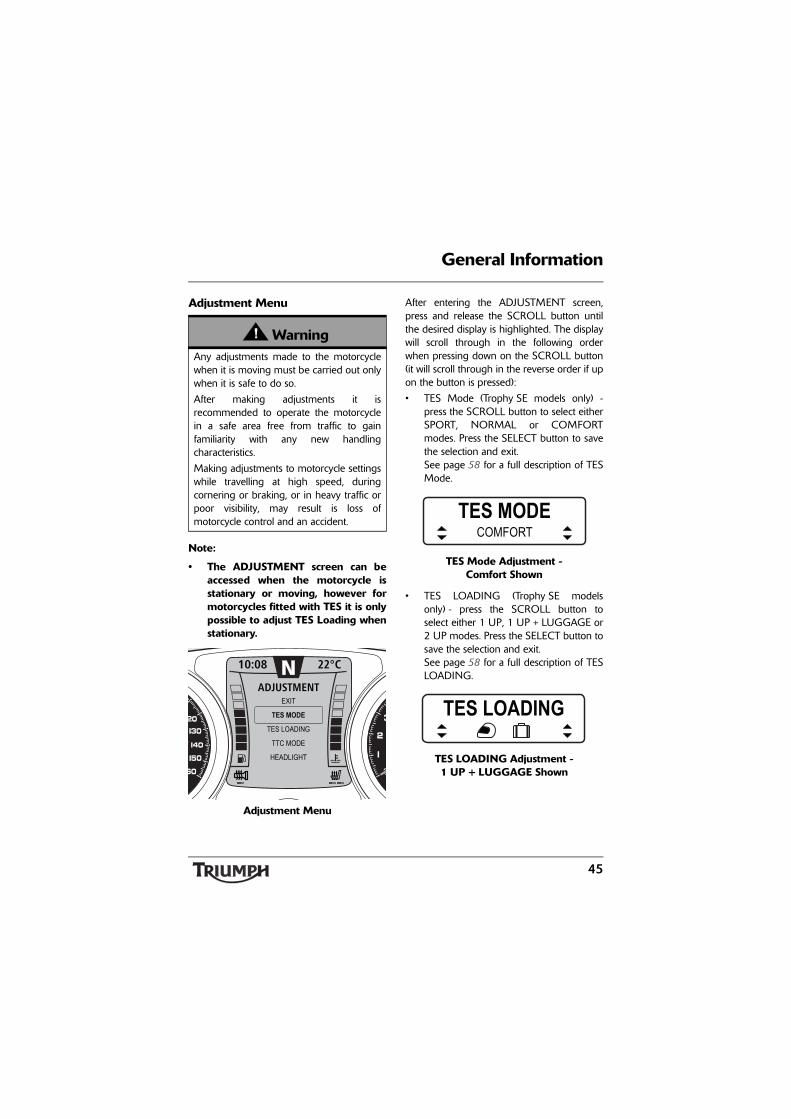
Adjustment Menu
Note:
• The ADJUSTMENT screen can beaccessed when the motorcycle isstationary or moving, however formotorcycles fitted with TES it is onlypossible to adjust TES Loading whenstationary.
Adjustment Menu
After entering the ADJUSTMENT screen,press and release the SCROLL button untilthe desired display is highlighted. The displaywill scroll through in the following orderwhen pressing down on the SCROLL button(it will scroll through in the reverse order if upon the button is pressed):
• TES Mode (Trophy SE models only) -press the SCROLL button to select eitherSPORT, NORMAL or COMFORTmodes. Press the SELECT button to savethe selection and exit.See page 58 for a full description of TESMode.
TES Mode Adjustment - Comfort Shown
• TES LOADING (Trophy SE modelsonly) - press the SCROLL button toselect either 1 UP, 1 UP + LUGGAGE or2 UP modes. Press the SELECT button tosave the selection and exit.See page 58 for a full description of TESLOADING.
TES LOADING Adjustment - 1 UP + LUGGAGE Shown
WarningAny adjustments made to the motorcyclewhen it is moving must be carried out onlywhen it is safe to do so.
After making adjustments it isrecommended to operate the motorcyclein a safe area free from traffic to gainfamiliarity with any new handlingcharacteristics.
Making adjustments to motorcycle settingswhile travelling at high speed, duringcornering or braking, or in heavy traffic orpoor visibility, may result is loss ofmotorcycle control and an accident.
10:08 N 22°C
TES LOADING
EXIT
TTC MODE
TES MODE
ADJUSTMENT
HEADLIGHT
TES MODECOMFORT
TES LOADING

46
General Information
• TTC MODE - press the SCROLL buttonto select either ON or OFF. Press theSELECT button to save the selection andexit.See page 55 for a full description of TTCMODE.
TTC Mode Adjustment - On Shown
• HEADLIGHT - press the SCROLL buttonto adjust the headlight using theadjustment slider between levels 1(lowest) to 10 (highest). Press the SELECTbutton to save the selection and exit.
Headlight Adjust
Changes made to the TES MODE, TESLOADING, TTC or HEADLIGHT settings viathe ADJUSTMENT screen are stored in a'current' profile, separately from the twosaved profiles.
This allows temporary changes to be made toa profile without editing a saved profile,however these changes will be lost when asaved profile is loaded.
To load a saved profile see page 47.
WarningAdjust road speed to suit the visibility andweather conditions in which the motorcycleis being operated.
Ensure that the headlight beams areadjusted to illuminate the road surfacesufficiently far ahead without blindingoncoming traffic. An incorrectly adjustedheadlight may impair visibility causing anaccident.
TTC MODEON
HEADLIGHT

47
General Information
Trip SetupAfter entering the TRIP SETUP screen, pressand release the SCROLL button until thedesired display is highlighted.
Trip Setup Screen
The display will scroll through in the followingorder when pressing down on the SCROLLbutton (it will scroll through in the reverseorder if up on the button is pressed):
• TRIP 1 ITEMS - pressing the SELECTbutton enters the TRIP 1 setup screenand prompts for the item to be set onthe upper display line (ITEM 1). Use theSCROLL button to select an option (seepage 41) and press SELECT.
Trip 1 Items - Upper Display Line
• The instruments will now prompt for theitem to be set on the lower display line(ITEM 2). Use the SCROLL button toselect an option (see page 41) and pressSELECT to exit.
Note:
• The same trip item cannot bedisplayed in the UPPER and LOWERposition at the same time.
Trip 1 Items - Lower Display Line
• TRIP 1 RESET - pressing SELECT resetsTRIP 1 data immediately.
• TRIP 2 ITEMS pressing the SELECTbutton enters the TRIP 2 setup screenand prompts for the item to be set onthe upper display line (UPPER). Use theSCROLL button to select an option (seepage 41) and press SELECT. The instruments will now prompt for theitem to be set on the lower display line(LOWER). Use the SCROLL button toselect an option (see page 41) and pressSELECT to exit.
Note:
• The same trip item cannot bedisplayed in the UPPER and LOWERposition at the same time.
10:08 N 22°C
TRIP 1 RESET
EXIT
TRIP 2 ITEMS
TRIP 1 ITEMS
TRIP SETUP
TRIP 2 RESET
AUTO RESET
TRIP 1 ITEMSUPPER
TRIP 1 ITEMSLOWER

48
General Information
• TRIP 2 RESET - pressing SELECT resetsthe TRIP 2 data immediately.
Note:
• The AUTO RESET function applies toTRIP 2 only. TRIP 1 must be resetmanually using the TRIP 1 RESETopposite, or the method describedon page 43.
• AUTO RESET - pressing the SELECTbutton enters the AUTO RESET setupscreen.
Auto Reset
• Press the SCROLL button to select eitherOFF, 1 HR, 2 HRS, 4 HRS and 8 HRs.Press the SELECT button to save theselection and exit.
After the set time has elapsed, Trip 2 will bereset to zero.
The following trip items will be reset:
• trip time;
• trip distance;
• average fuel consumption;
• fuel used;
• average speed.
Bike SetupAfter entering the BIKE SETUP screen, pressand release the SCROLL button until thedesired display is highlighted.
Trip Setup Screen
The display will scroll through in the followingorder when pressing down on the SCROLLbutton (it will scroll through in the reverseorder if up on the button is pressed):
• LANGUAGE - pressing the SELECTbutton enters the LANGUAGE setupscreen.
Language Select
• Press the SCROLL button to select eitherENGLISH, FRENCH, ITALIAN,GERMAN, SPANISH, SWEDISH,DUTCH OR PORTUGUESE. Press theSELECT button to save the selection andexit.
AUTO RESET4 HRS
10:08 N 22°C
INDICATORS
EXIT
SET CLOCK
LANGUAGE
BIKE SETUP
SET UNITS
BRIGHTNESS
LANGUAGEENGLISH

49
General Information
• INDICATORS - pressing the SELECTbutton enters the Indicators setup screen(see page 52).
Indicator Self Cancelling Select
• Press the SCROLL button to select eitherAUTO or MANUAL. Press the SELECTbutton to save the selection and exit.
• CLOCK - pressing the SELECT buttonenters the SET CLOCK setup screen andprompts for 12HR or 24HR.
Clock Set - 24 hour Shown
• Press the SCROLL button to select thedesired clock display and press SELECT.The instruments will now prompt SETHOUR. Use the SCROLL button toselect the desired clock display and pressSELECT.The instruments will now prompt SETMINUTE. Use the SCROLL button toselect the desired clock display and pressSELECT to save and exit.
• UNITS - pressing the SELECT buttonenters the UNITS setup screen andprompts for MILE or KM.
Units Select
• Press the SCROLL button to select thedesired unit and press SELECT.The instruments will now promptECONOMY. If MILE is selected theoptions available will be MPG (UK) orMPG (US). If KM is selected the optionsavailable will be KM/L or L/100 KM. Usethe SCROLL button to select the desiredunit and press SELECT.
Note:
• If MILE is selected above, theinstruments will now prompt TEMP(temperature). If KM is selected, °Cwill be set by default.
• Use the SCROLL button to select either°F or °C and press SELECT.
• If TPMS is fitted, the instruments willnow prompt PRESSURE. Use theSCROLL button to select either PSI orBAR and press SELECT to save and exit.
INDICATORSAUTO
SET CLOCK24 HR
SET UNITSDISTANCE MILE

50
General Information
• BRIGHTNESS - press the SCROLLbutton to adjust the instrumentbrightness using the adjustment sliderbetween levels 1 (lowest) to 10 (highest).Press the SELECT button to save theselection and exit.
Brightness Adjust
The instruments are also fitted with anambient light sensor which adjusts theinstrument brightness to an optimal level forall riding conditions. This allows the rider’spreferred setting to be adjusted automaticallyto suit riding in daylight, dusk and night-timeconditions.
Note:
• Setting the brightness under artificiallighting (in a garage for example)may produce unpredictable results.Always adjust the brightness settingunder natural light.
Lower Message AreaThis area displays warning and informationmessages, using different layouts dependingupon the message type.
Warning MessagesThe following Warning messagesmay be displayed if a fault isdetected:
• COOLANT TEMP HIGH (see page 27);
• OIL PRESSURE LOW (see page 27)
• BATTERY LOW (see page 27);
• ABS SYSTEM DISABLED (see page 29);
• CHECK MANUAL - TES SYSTEM (seepage 58);
• TTC SYSTEM DISABLED (see page 55);
• FRONT/REAR TIRE PRESSURE LOW(see page 52).
Information MessagesThe following informationmessages may be displayed:
• PLEASE WAIT - TES SYSTEMCALIBRATING (accompanied by a 'wait'icon) (see page 58);
• PLEASE WAIT - TES SYSTEMADJUSTMENT IN PROGRESS(accompanied by a 'wait' icon) (seepage 58);
• TES SYSTEM ADJUSTMENTCOMPLETE (see page 58);
• TPMS - BATTERY LOW FRONT/REARTIRE (see page 52);
• CHECK MANUAL - TPMS SYSTEMFAULT - SENSOR SIGNAL (seepage 52);
• CHECK MANUAL - CRUISECONTROL DISABLED (see page 59);
BRIGHTNESS
51
General Information
• AUDIO OFF - LOW VOLTAGE (refer tothe Audio System Handbook);
• AUDIO NOT FOUND (refer to theAudio System Handbook).
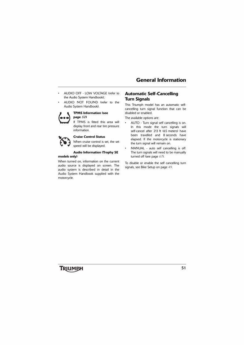
TPMS Information (see page 52)If TPMS is fitted this area willdisplay front and rear tire pressureinformation.
Cruise Control StatusWhen cruise control is set, the setspeed will be displayed.
Audio Information (Trophy SE models only)When turned on, information on the currentaudio source is displayed on screen. Theaudio system is described in detail in theAudio System Handbook supplied with themotorcycle.
Automatic Self-Cancelling Turn SignalsThis Triumph model has an automatic self-cancelling turn signal function that can bedisabled or enabled.
The available options are:
• AUTO - Turn signal self cancelling is on.In this mode the turn signals willself-cancel after 213 ft (65 meters) havebeen travelled and 8 seconds haveelapsed. If the motorcycle is stationarythe turn signal will remain on.
• MANUAL - auto self cancelling is off.The turn signals will need to be manuallyturned off (see page 67).
To disable or enable the self cancelling turnsignals, see Bike Setup on page 49.

52
General Information
Units of Measure (Imperial, US or Metric)UNITS has two selectable display modes,MILE and KM. If mile is selected it is possibleto customize the display to show units in:
• MPG (UK) - the fuel consumption will bemeasured in imperial gallons;
• MPG (US) - the fuel consumption will bemeasured in US gallons;
• temperature - °C or °F;
• pressure - PSI or BAR.
If km is selected it is possible to customize thedisplay to show units in:
• L/100 KM - the fuel consumption will bemeasured in liters of fuel per 100 km(62 miles);
• KM/L - the fuel consumption will bemeasured in kilometers per liter of fuel;
• temperature - the default temperaturefor metric units is °C;
• pressure - PSI or BAR.
To access the units display; see BIKE SETUPon page 49.
Tire Pressure Monitoring System (TPMS) (if equipped)
Note:
• The Tire Pressure MonitoringSystem (TPMS) is standardequipment on Trophy SE models,and available as an accessory onTrophy models. On Trophy modelsTPMS must only be fitted by yourauthorized Triumph dealer. TheTPMS display will then be activatedby your authorized Triumph dealer.
WarningThe daily check of tire pressures must notbe excluded because of the mounting ofthe TPMS. Check the tire pressure whenthe tires are cold and using an accurate tirepressure gauge (see page 144).
Use of the TPMS system to set inflationpressures may lead to incorrect tirepressures leading to loss of motorcyclecontrol and an accident.

53
General Information
FunctionTire pressure sensors are fitted to the frontand rear wheels. These sensors measure theair pressure inside the tire and transmitpressure data to the instruments. Thesesensors will not transmit the data until themotorcycle is travelling at a speed greaterthan 12 mph (20 km/h). Two dashes will bevisible in the display area until the tirepressure signal is received.
An adhesive label will be fitted to the wheelrim to indicate the position of the tirepressure sensor, which is near the valve.
TPMS Sensor ID NumberAn ID number for each tire pressure sensor isprinted on a label which is attached to thesensor. This number may be required by thedealer for service or diagnostics.
If the TPMS has been fitted at the factory,labels identifying the front and rear TPMSsensor ID numbers will be affixed to thespaces on page 53.
If the TPMS is being fitted to the motorcycleas an accessory, ensure that the dealerrecords the front and rear TPMS sensor IDnumbers in the spaces provided below.
Front Sensor Rear Sensor

54
General Information
System Display
1. TPMS symbol2. Tire pressure display
The tire pressure display can be accessedthrough Trip 1 or Trip 2 (see page 41).
When the tire pressure monitoring systemhas been selected, — — PSI or BAR(information on how to set the desired displayunits can found on page 49) will be visible,for each tire, in the display screen until themotorcycle is travelling at a speed greaterthan 12 mph (20 km/h) and the tire pressuresignal is received.
Sensor BatteriesWhen the battery voltage in a pressuresensor is low, TPMS - BATTERY LOWFRONT/REAR TIRE will be displayed foreight seconds. If the batteries are completelyflat, only dashes will be visible in the displayscreen, the red TPMS warning light will beon and the TPMS symbol will flashcontinuously. Contact your authorizedTriumph dealer to have the sensor replacedand the new serial number recorded in thespaces provided on page 53.
1. Tire pressure warning light2. Instrument message
TPMS SymbolWith the ignition switch turned to the ONposition, if the TPMS symbol flashes for10 seconds and then remains on there is afault with the TPMS system. The messageCHECK MANUAL - TPMS SYSTEM FAULT -SENSOR SIGNAL will be displayed foreight seconds in the lower message area.
Contact your authorized Triumph dealer tohave the fault rectified.
TRIP 1
MPH0
10:08 N 22°C
1892ODO
F 36R 42 PSI
PSI
chdo 1 2
TRIP 1
MPH0
10:08 N 22°C
1892ODO
144.2
BATTERY LOWWARNINGFRONT TYRE
chdo 1 2

55
General Information
Tire PressuresThe tire pressures shown on your instrumentpanel indicate the actual tire pressure at thetime of selecting the display. This may differfrom the inflation pressure set when the tiresare cold because tires become warmerduring riding, causing the air in the tire toexpand and the inflation pressure to increase.The cold inflation pressures specified byTriumph take account of this.
Owners must adjust tire pressures only whenthe tires are cold, using an accurate tirepressure gauge (see page 144), and must notuse the tire pressure display on theinstruments.
Replacement TiresWhen replacing tires, always have anauthorized Triumph dealer mount your tiresand ensure they are aware that tire pressuresensors are mounted to the wheels (seepage 146).
Triumph Traction Control (TTC)
Triumph Traction Control helps to maintaintraction when accelerating on wet/slipperyroad surfaces. If sensors detect that the rearwheel is losing traction (slipping), the tractioncontrol system will engage and alter theengine power until traction to the rear wheelhas been restored. The traction controlwarning light will flash while it is engagedand the rider may notice a change to thesound of the engine.
Note:
• Traction control will not function ifthere is a malfunction with the ABSsystem. The warning lights for theABS, traction control and the MILwill be illuminated.
WarningThe tire pressure monitoring system is notto be used as a tire pressure gauge whenadjusting the tire pressures. For correct tirepressures, always check the tire pressureswhen the tires are cold, using an accuratetire pressure gauge (see page 144).
Use of the TPMS system to set inflationpressures may lead to incorrect tirepressures leading to loss of motorcyclecontrol and an accident.
WarningTriumph Traction Control is not a substitutefor riding appropriately for the prevailingroad and weather conditions. The tractioncontrol cannot prevent loss of traction dueto:
• excessive speed when entering turns;
• accelerating at a sharp lean angle;
• braking.
Traction control can not prevent the frontwheel from slipping.
Failure to observe any of the above mayresult in loss of motorcycle control and anaccident.

56
General Information
Triumph Traction Control Settings
The Triumph Traction Control can be set toone of the following conditions:
• ON - the traction control will engage tocontrol rear wheel slip.The warning light will be off but will flashon and off when the traction control isworking to limit the rear wheel slipping;
• OFF - traction control is disabled and thewarning light is constantly on.Traction control will be enabled againwhen the ignition is turned off and thenon.
To access the TTC settings, seeADJUSTMENT on page 48.
Triumph Electronic Suspension (TES) (if equipped)
The Triumph Electronic Suspension (TES)system controls adjustment of the front andrear suspension damping and rearsuspension pre-load settings.
TES allows a convenient remote adjustmentof the riding MODE (damping settings) andLOADING (pre-load settings) via theinstruments while the motorcycle is stationary(MODE and LOADING settings) or moving(MODE only).
The three MODE (damping) optionsavailable are:
• COMFORT;
• NORMAL;
• SPORT.
The three LOADING (pre-load) optionsavailable are:
• 1 UP;
• 1 UP+LUGGAGE;
• 2 UP.
To access the TES settings, seeADJUSTMENT on page 48.
WarningDo not attempt to adjust the tractioncontrol settings while the motorcycle is inmotion as this may lead to loss ofmotorcycle control and an accident.
WarningIf the traction control is disabled, themotorcycle will handle as normal butwithout traction control. In this situationaccelerating too hard on wet/slippery roadsurfaces may cause the rear wheel to slip,and may result in loss of motorcyclecontrol and an accident.
WarningAfter adjusting the suspension, operate themotorcycle in an area free from traffic togain familiarity with the new settings. Donot loan your motorcycle to anyone as theymay change the suspension settings fromthe one you are familiar with causing lossof control or an accident.

57
General Information
Once a mode or loading adjustment hasbeen selected, and the engine is running, thesuspension will start to adjust, the TESwarning light will flash once every secondand the lower message area will display themessage PLEASE WAIT - TES SYSTEMADJUSTMENT IN PROGRESS, until thesystem has finished adjusting.
TES Adjustment in Progress
Once adjustment is complete the messageTES SYSTEM ADJUSTMENT COMPLETEwill be displayed and the warning light will goout.
Adjustment Complete
If the engine is not running when a profile isloaded, or the ADJUSTMENT menu is usedto change the MODE or LOADING settings,the request to change the settings will besaved.
Once the engine has started, the adjustmentwill be made as described above.
If the engine is not started before the ignitionis switched off then the requested setting willbe lost and the previous settings will be used.
It is also possible to store the TES settings totwo separate profiles (see page 47), allowingsettings to be stored for different rider’sindividual preferences, different riding stylesor different loading conditions.
System CalibrationThe system will re-calibrate the damperadjustment motors each time the ignition isturned on and the pre-load adjustmentmotor after every 50 ignition on cycles, oncethe engine is started.
Damper adjustment motor calibration takesapproximately 2 - 3 seconds, and pre-loadmotor calibration takes around20 - 30 seconds.
TRIP 1
MPH0
10:08 N 26°C
1892ODO
144.2
TES SYSTEMADJUSTMENTIN PROGRESS
chdo
TRIP 1
MPH0
10:08 N 26°C
1892ODO
144.2
chdo
TES SYSTEMADJUSTMENTCOMPLETE

58
General Information
The warning light will flash twice everysecond during system re-calibration.
1. TES warning lightTo allow the system to calibrate correctly, thefollowing procedure must be adhered to:
• Turn the ignition on. Do not start theengine.
• Wait for the warning light to stop flashingindicating that damper adjustment motorcalibration is complete.
• Start the engine. If the warning lightresumes flashing, the pre-load motor isbeing calibrated.
• Wait for the warning light to stop flashingbefore riding the motorcycle.
Failure to follow this procedure will cause there-calibration to be halted and the warninglight to remain lit. In this case the warning light will extinguishonce the re-calibration is next allowed tocomplete.
Cruise Control
TRIP 1
MPH0
10:08 N 26°C
1892ODO
144.2
1chdo
WarningCruise control must only be used whereyou can drive safely at a steady speed.
Cruise control should not be used whenriding in heavy traffic, on roads withsharp/blind bends or when they areslippery.
Using cruise control in heavy traffic, onroads with sharp/blind bends or when theyare slippery, may result in loss ofmotorcycle control and an accident.
WarningThis Triumph motorcycle should beoperated within the legal speed limits forthe particular road travelled. Operating amotorcycle at high speeds can bepotentially dangerous since the timeavailable to react to given traffic situationsis greatly reduced as speed increases.Always reduce speed in consideration ofweather and traffic conditions.

59
General Information
Note:
• Cruise control will not function ifthere is a malfunction with the ABSsystem and the ABS warning light isilluminated.
The cruise control buttons are located on theright hand switch cube and can be operatedwith minimum movement by the rider.
Cruise control can be switched on or off atany time but it can not be activated until allthe conditions described on page 59 havebeen met.
Activating Cruise Control
Note:
• The cruise control indicator light willnot illuminate until cruise control hasbeen activated by pressing SET/- onthe adjust button.
To turn on the cruise control, press in theon/off button.
1. Cruise control ON/OFF button2. Cruise control adjust button, SET/-3. Cruise control adjust button, RES/+
WarningOnly operate this Triumph motorcycle athigh speed in closed-course on-roadcompetition or on closed-course racetracks.High-speed operation should only then beattempted by riders who have beeninstructed in the techniques necessary forhigh-speed riding and are familiar with themotorcycle's behavior in all conditions.
High-speed operation in any othercircumstances is dangerous and will lead toloss of motorcycle control and an accident.
1 2
3
chdc

60
General Information
To activate cruise control, the followingconditions have to be met:
• The motorcycle is travelling at a speedbetween 30 to 100 mph (48 to 160 km/h);
• The motorcycle is in 4th gear or higher;
• The SET/- on the adjust button ispressed.
The cruise control light will illuminateindicating that cruise control is active and set,and the set speed will be displayed in thelower display area of the multi-functiondisplay. The current set speed will be storeduntil the ignition is turned off, and can beresumed by pressing and releasing the RES/+end of the adjust button (see page 62).
1. Cruise control warning light2. Set speed
Note:
• Riding with either brake actuated orthe clutch not fully released willprevent operation of the cruisecontrol system.
Deactivating Cruise ControlThe cruise control can be deactivated by oneof the following methods:
• Roll the throttle fully forward;
• Pull the clutch lever;
• Operate the front or rear brake;
• Increase speed by using the throttle formore than 60 seconds;
• Press and release the on/off button onthe right hand switch cube.
Provided the cruise control has not beendeactivated by turning the ignition switch tothe OFF position, the previous set speed canbe resumed by pressing and releasing theRES/+ end of the adjust button. Themotorcycle speed has to be between30 to 100 mph (48 to 160 km/h) and in4th gear or higher.
TRIP 1
MPH60
10:08 6 22
1892ODO
144.2
MPH60
chdo
21

61
General Information
Resuming the Cruise Control Set Speed
Provided the cruise control has not beendeactivated by turning the ignition switch tothe OFF position, the previous set speed canbe resumed by pressing and releasing theRES/+ end of the adjust button provided thethe conditions described on page 59 havebeen met.
1. Cruise control ON/OFF button2. Cruise control adjust button, SET/-3. Cruise control adjust button, RES/+
The set speed will remain in the cruise controlmemory until the ignition switch has beenturned to the OFF position.
Increasing Speed while in Cruise ControlTo increase the speed, press and release theRES/+ end of the adjust button. Each press ofthe button will increase the speed by 1 mphor 1 km/h. If the button is held, the speed willcontinuously increase in single digitincrements. When the desired speed isshown in the display, stop pressing the adjustbutton.
While increasing the speed, the displayscreen in the instruments will show the newset speed in the lower display area. The newspeed will flash until the motorcycle hasachieved that speed.
After 4 seconds the display screen willchange to the previous display.
Note:
• If riding up a steep incline and cruisecontrol is unable to maintain the setspeed, the instruments will show theset speed flashing until themotorcycle has regained the speed.
An alternative way to increase the speed incruise control is to accelerate to the desiredspeed using the throttle grip and then pressthe SET/- end of the adjust button.
WarningWhen resuming cruise control, alwaysensure that the traffic conditions aresuitable for the set speed.
Using cruise control in heavy traffic, onroads with sharp/blind bends or when theyare slippery, may result in loss ofmotorcycle control and an accident.
1 2
3
chdc

62
General Information
Decreasing Speed while in Cruise ControlTo decrease speed, press and release theSET/- end of the adjust button. Each press ofthe button will decrease the speed by 1 mphor 1 km/h. If the button is held, the speed willcontinuously decrease in single digitincrements.
While decreasing the speed, the displayscreen in the instruments will show the newset speed.
When the desired speed has been achieved,stop pressing the adjust button. After4 seconds the display screen will change tothe previous display.
Ignition Key
1. Key number tagIn addition to operating the steeringlock/ignition switch, the ignition key isrequired to operate the seat lock, fuel tankcap, panniers and top box (if equipped).
When the motorcycle is delivered from thefactory, two keys are supplied together with asmall tag bearing the key number. Make anote of the key number and store the sparekey and key number tag in a safe place awayfrom the motorcycle.
A transponder is fitted within the key to turnoff the engine immobilizer. To ensure theimmobilizer functions correctly, always haveonly one of the ignition keys near the ignitionswitch. Having two ignition keys near theswitch may interrupt the signal between thetransponder and the engine immobilizer. Inthis situation the engine immobilizer willremain active until one of the ignition keys isremoved.
1

63
General Information
Always get replacement keys from yourauthorized Triumph dealer. Replacement keysmust be 'paired' with the motorcycle’simmobilizer by your authorized Triumphdealer.
Ignition Switch/Steering Lock
1. Ignition switch/steering lock2. LOCK position3. OFF position4. ON position5. PARK position
Engine ImmobilizerThe ignition barrel housing acts as theantenna for the engine immobilizer.
When the ignition switch is turned to the OFFposition and the ignition key is removed, theengine immobilizer is on (see page 29). Theengine immobilizer is turned off when theignition key is in the ignition switch and it isturned to the ON position.
CautionDo not store the spare key with themotorcycle as this will reduce all aspects ofsecurity.
PU
SH
P
OFF
ON
3
2
5
1
4

64
General Information
Ignition Switch PositionsThis is a four position, key operated switch.The key can be removed from the switchonly when it is in the OFF, LOCK or P (PARK)position.
TO LOCK: Turn the handlebar fully to theleft, turn the key to the OFF position, pushand fully release the key, then rotate it to theLOCK position.
PARKING: Turn the key from the LOCKposition to the P position. The steering willremain locked, and the position lights will beswitched on.
Note:
• Do not leave the steering lock in theP position for long periods of time asthis will cause the battery todischarge.
WarningFor reasons of security and safety, alwaysmove the ignition switch to the OFFposition and remove the key when leavingthe motorcycle unattended.
Any unauthorized use of the motorcyclemay cause injury to the rider, other roadusers and pedestrians and may also causedamage to the motorcycle.
WarningWith the key in the LOCK or P position thesteering will become locked.
Never turn the key to the LOCK orP positions while the motorcycle is movingas this will cause the steering to lock.Locked steering will cause loss ofmotorcycle control and an accident.

65
General Information
Right Handlebar Switches
1. Engine stop switch2. Starter button3. Cruise control adjust button4. Cruise control ON/OFF button
Engine Stop SwitchIn addition to the ignition switch being turnedto the ON position, the engine stop switchmust be in the RUN position for themotorcycle to operate.
The engine stop switch is for emergency use.If an emergency arises which requires theengine to be stopped, move the engine stopswitch to the STOP position.
Note:
• Although the engine stop switchstops the engine, it does not turn offall the electrical circuits and maycause difficulty in restarting theengine due to a discharged battery.Ordinarily, only the ignition switchshould be used to stop the engine.
Starter ButtonThe starter button operates the electricstarter. For the starter to operate, the clutchlever must be pulled to the handlebar.
Note:
• Even if the clutch lever is pulled tothe handlebar, the starter will notoperate if the side stand is down anda gear is engaged.
Cruise Control ON/OFF ButtonWhen the cruise control button is pressed in,the cruise control is on (see page 59). Thebutton will remain in until it is pressed againto turn off the cruise control.
Cruise Control Adjust ButtonThe cruise control adjust button is a two wayswitch with the top marked RES/+ and thebottom marked SET/- (see page 59).
4 2
3
1
chdc
CautionDo not leave the ignition switch in theON position unless the engine is runningas this may cause damage to electricalcomponents and will discharge the battery.

66
General Information
Left Handlebar Switches
1. Headlight dimmer switch2. Direction turn signal switch3. Horn button4. Pass button5. Instrument SCROLL button6. Instrument SELECT button7. Windshield adjustment switch8. Heated grips switch (heated grips
are available as an accessory)9. Audio controls (if equipped)10. Audio PRESET button (if equipped)11. Audio MODE/MENU button (if
equipped)
Note:
• The audio system (if equipped) isdescribed in detail in the AudioSystem Handbook supplied with themotorcycle.
Headlight Dimmer SwitchHigh or low beam can be selected with theheadlight dimmer switch. To select highbeam, push the switch forward. To select lowbeam, push the switch rearwards. When thehigh beam is turned on, the high beamindicator light will illuminate.
Note:
• A lighting on/off switch is not fittedto this model. The position light,brake/tail light and license plate lightall function automatically when theignition is turned to the ON position.
• The headlight will only functionwhen the ignition switch is turned tothe ON position and the engine isrunning.An alternate way to turn on theheadlight, without the enginerunning, is to pull in the clutch leverthen turn the ignition to the ONposition. The headlight will be onand remain on when the clutch leveris released.The headlight will go off whilepressing the starter button until theengine starts.
chsb
4
79
51
2
3 6 8 10 11

67
General Information
Direction Turn Signal SwitchWhen the turn signal switch is pushed to theleft or right and released, the correspondingdirection turn signals will flash on and off.
The turn signal self cancel system becomesactive eight seconds after operating adirection turn signal. Eight seconds afterturning the direction turn signal on and afterriding a further 213 ft (65 meters), the turnsignal self cancel system will automaticallyturn off the turn signals. The turn signals canbe cancelled manually.
To manually turn off the turn signals, pressand release the turn signal switch in thecentral position.
To disable the turn signal self cancel system,see page 52.
Horn ButtonWhen the horn button is pushed, with theignition switch turned to the ON position, thehorn will sound.
Pass Button
Note:
• The pass button will only operatewhen the engine is running.
When the pass button is pressed, theheadlight main beam will be switched on. Itwill remain on as long as the button is held inand will turn off as soon as the button isreleased.
Instrument SCROLL ButtonWhen the SCROLL button is pressed andreleased it will scroll through the menu visiblein the instrument's display screen.
Instrument SELECT ButtonWhen the SELECT button is pressed it willselect the menu item highlighted in theinstrument's display screen.
1. SCROLL button, up2. SCROLL button, down3. SELECT button
3chsb_2
12

68
General Information
Windshield and Heated Grips Switch Unit
1. Windshield switch 2. Heated grips switch
Motorcycles without AudioThe windshield and heated grip switch islocated on the left hand handlebar, next tothe left handlebar switch cube.
For windshield adjustment see page 84.
For heated grip operation see page 80.
Motorcycles with AudioMotorcycles with audio fitted have anadditional set of switches installed next to thewindshield and heated grip switch.
The audio system is described in detail in theAudio System Handbook supplied with themotorcycle.
Hazard Warning LightsTo turn the hazard warning lights on or off,press and release the hazard warning lightswitch on the instruments.
The ignition must be switched on for thehazards warning lights to function, but willremain on if the ignition is switched off untilthe hazard warning light switch is pressedagain.
1. Hazard warning light switch
2chsb_1
1
1

69
General Information
Throttle Control
1. Throttle open position2. Throttle closed position3. Cruise control cancel position
This Triumph model has an electronic throttletwist grip to open and close the throttles viathe engine control unit. There are no direct-acting cables in the system.
The throttle grip has a resistive feel to it as it isrolled rearwards to open the throttles. Whenthe grip is released it will return to the throttleclosed position by its internal return springand the throttles will close.
From the closed position, the throttle twistgrip can be rolled forwards 3 - 4 mm todeactivate the cruise control (see page 60).
There are no user adjustments for the throttlecontrol.
If there is a malfunction with the throttlecontrol the malfunction indicator light (MIL)becomes illuminated and one of thefollowing engine conditions may occur:
• MIL illuminated, restricted engine RPMand throttle movement;
• MIL illuminated, limp home mode withthe engine at a fast idle condition only;
• MIL illuminated, engine will not start.
For all of the above conditions contact anauthorized Triumph dealer as soon aspossible to have the fault checked andrectified.
Brake UseAt low throttle opening (approximately 20°),the brakes and throttle can be used together.
At high throttle opening (greater than 20°), ifthe brakes are applied for greater than2 seconds the throttles will close and theengine speed will reduce. To return to normalthrottle operation, release the throttle control,release the brakes and then re-open thethrottle.
1
2 3
WarningReduce speed and do not continue to ridefor longer than is necessary with themalfunction indicator light illuminated. Thefault may adversely affect engineperformance, exhaust emissions and fuelconsumption. Reduced engineperformance could cause a dangerousriding condition, leading to loss of controland an accident. Contact an authorizedTriumph dealer as soon as possible to havethe fault checked and rectified.

70
General Information
Fuel Requirement/Refuelling
Fuel Grade
This Triumph motorcycle is designed to runon unleaded gasoline with a CLC or AKIoctane rating (R+M)/2 of 87 or higher.Federal regulations require that pumpsdelivering unleaded gasoline are marked'UNLEADED' and that the Cost of LivingCouncil (CLC) or Anti-Knock Index (AKI)octane rating is also displayed. These ratingsare an average of the Research OctaneNumber (RON) and the Motor OctaneNumber (MON).
Note:
• If 'knocking' or 'pinging' occurs at asteady engine speed under normalload, use a different brand ofgasoline or gasoline which has ahigher octane rating.
Oxygenated GasolineTo help in meeting clean air standards, someareas of the U.S. use oxygenated gasoline tohelp reduce harmful emissions. Thesegasolines are a blend of conventionalgasoline and another compound such asalcohol. This Triumph motorcycle will give itsbest performance when using unleadedgasoline. However, the following should beused as a guide if you use any oxygenatedfuels.
EthanolEthanol fuel is a mixture of 10% Ethanol and90% gasoline and is often described underthe names 'gasohol', 'Ethanol enhanced', or'contains Ethanol'. This fuel may be used inyour Triumph motorcycle.
MTBE (Methyl Tertiary Butyl Ether)The use of gasolines containing up to 15%MTBE (Methyl Tertiary Butyl Ether) ispermitted in this Triumph motorcycle.
Methanol
CautionThe use of leaded gasoline is illegal insome countries, states or territories. Checklocal regulations before using leadedgasoline.
Pb
CautionFuels containing methanol should not beused as damage to components in the fuelsystem can be caused by contact withmethanol.
CautionBecause of the generally higher volatility ofoxygenated fuels, starting, engineresponse and fuel consumption may beadversely affected by their use. Should anyof these difficulties be experienced, run themotorcycle on normal unleaded gasoline.

71
General Information
Fuel Tank Cap
1. Fuel tank capTo open the fuel tank cap, lift up the flapcovering the lock itself. Insert the key into thelock and turn the key clockwise.
To close and lock the cap, push the cap downinto place with the key inserted, until the lock'clicks' into place. Withdraw the key and closethe key cover.
WarningTo help reduce hazards associated withrefuelling, always observe the followingfuel safety instructions:
Gasoline (fuel) is highly flammable and canbe explosive under certain conditions.When refuelling, turn the ignition switch tothe 'OFF' position.
Do not smoke.
Do not use a mobile telephone.
Make sure the refuelling area is wellventilated and free from any source offlame or sparks. This includes anyappliance with a pilot light.
Never fill the tank until the fuel level risesinto the filler neck. Heat from sunlight orother sources may cause the fuel toexpand and overflow creating a firehazard.
After refuelling always check that the fuelfiller cap is correctly closed and locked.
Because gasoline (fuel) is highlyflammable, any fuel leak or spillage, or anyfailure to observe the safety advice givenabove will lead to a fire hazard, whichcould cause damage to property, injury topersons or death.
CautionClosing the cap without the key insertedwill damage the cap, tank and lockmechanism.
chsx
1

72
General Information
Filling the Fuel TankAvoid filling the tank in rainy or dustyconditions where airborne material cancontaminate the fuel.
Fill the fuel tank slowly to help preventspillage. Do not fill the tank to a level abovethe bottom of the filler neck. This will ensurethere is enough air space to allow for fuelexpansion if the fuel inside the tank expandsthrough absorption of heat from the engineor from direct sunlight.
1. Maximum fuel level2. Fuel filler neck3. Air space
After refuelling always check that the fuelfiller cap is correctly closed and locked.
CautionContaminated fuel may cause damage tofuel system components.
cbdf
1 2 3
WarningOverfilling the tank can lead to fuelspillage.
If fuel is spilled, thoroughly clean up thespillage immediately and dispose of thematerials used safely.
Take care not to spill any fuel on theengine, exhaust pipes, tires or any otherpart of the motorcycle.
Because fuel is highly flammable, any fuelleak or spillage, or any failure to observethe safety advice given above may lead toa fire hazard, which could cause damage toproperty and injury or death to persons.
Fuel spilled near to, or onto the tires willreduce the tire's ability to grip the road.This will result in a dangerous ridingcondition potentially causing loss ofmotorcycle control and an accident.

73
General Information
Brake and Clutch Lever Adjusters
1. Adjuster wheel, brake lever shown2. Arrow mark
An adjuster is fitted to both the front brakeand clutch levers.
The adjusters allow the distance from thehandlebar to the lever to be changed to oneof five positions for the front brake lever orfour positions for the clutch lever, to suit thespan of the operator's hands.
To adjust the lever, push the lever forwardand turn the adjuster wheel to align one ofthe numbered positions with the arrow markon the lever holder.
The distance from the handlebar grip to thereleased lever is shortest when set to numberfive, and longest when set to number one.
WarningDo not attempt to adjust the lever with themotorcycle in motion as this may lead toloss of motorcycle control and an accident.
After adjusting the lever, operate themotorcycle in an area free from traffic togain familiarity with the new lever setting.Do not loan your motorcycle to anyone asthey may change the lever setting from theone you are familiar with causing loss ofcontrol or an accident.
2 1
chde

74
General Information
Stands
Side Stand
1. Side standThe motorcycle is equipped with a side standon which the motorcycle can be parked.
Note:
• When using the side stand, alwaysturn the handlebars fully to the leftand leave the motorcycle in firstgear.
Whenever the side stand is used, beforeriding, always ensure that the side stand isfully up after first sitting on the motorcycle.
For instructions on safe parking, refer to the'How to Ride the Motorcycle' section.
Center Stand
1. Center standTo set the motorcycle on the center stand,step down firmly on the foot finder part ofthe stand, then lift the motorcycle up and tothe rear using the handhold in the rearfootrest hanger or the pillion grab handle.
For instructions on safe parking, refer to the'How to Ride the Motorcycle' section.
WarningThe motorcycle is fitted with an interlocksystem to prevent it from being riddenwith the side stand in the down position.
Never attempt to ride with the side standdown or interfere with the interlockmechanism as this will cause a dangerousriding condition leading to loss ofmotorcycle control and an accident.
chsn_1
1
CautionDo not use body panels or the seat as ahand-hold when placing the motorcycle onthe center stand as this will cause damage.
chsn_2
1

75
General Information
Tool Kit, Owner’s Handbook and Audio System HandbookThe tool kit and Owner’s Handbook arelocated beneath the pillion's seat (seepage 79).
If the Triumph Audio System is fitted, theAudio System Handbook is located beneaththe pillion's seat, with the Owner’sHandbook.
Seats
Seat CareTo prevent damage to the seat or seat cover,care must be taken not to drop or lean theseat against any surface which may damagethe seat or seat cover.
See page 163 for seat cleaning information.
CautionTo prevent damage to the seat or seatcover, care must be taken not to drop theseat. Do not lean the seat against themotorcycle or any surface which maydamage the seat or seat cover. Instead,place the seat, with the seat cover facingupwards, on a clean, flat surface which iscovered with a soft cloth.
Do not place any item on the seat whichmay cause damage or staining to the seatcover.
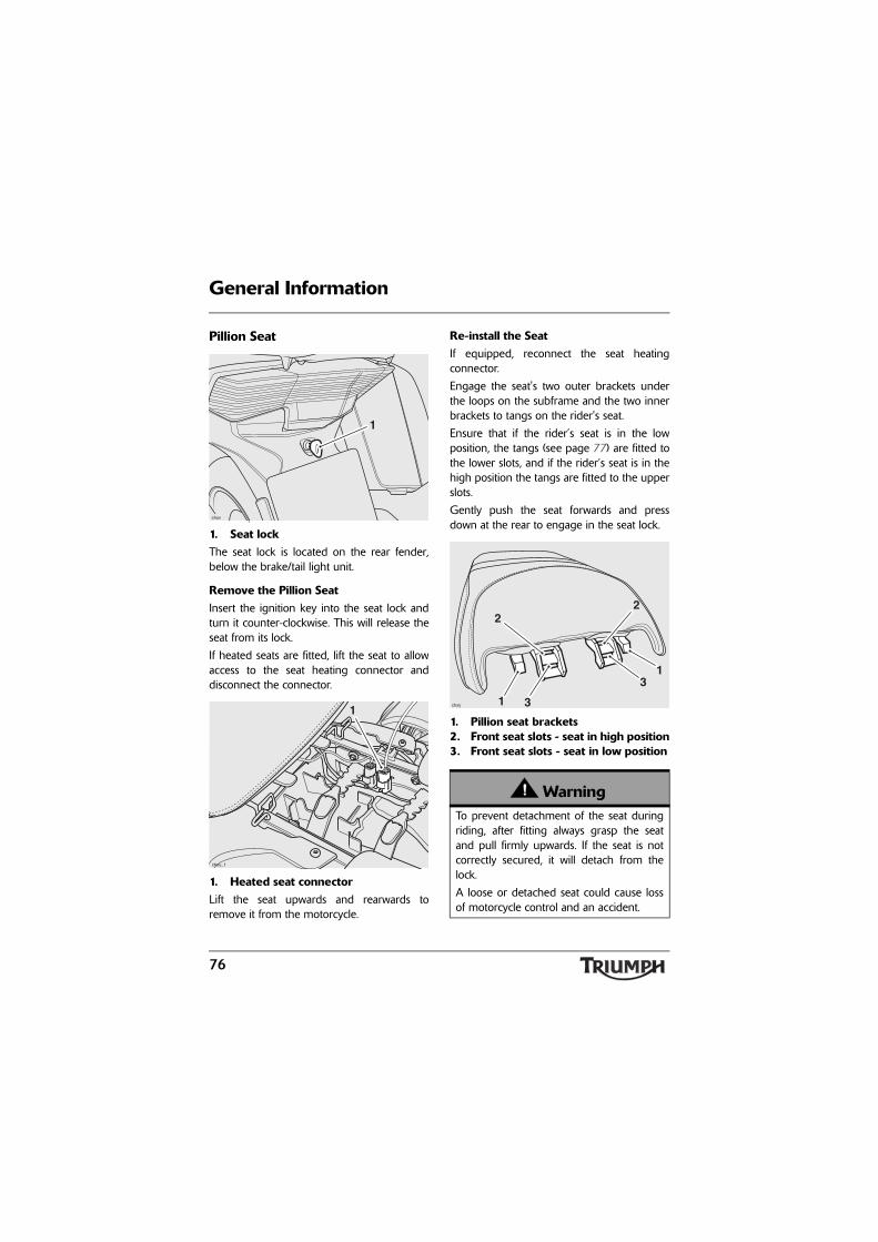
76
General Information
Pillion Seat
1. Seat lockThe seat lock is located on the rear fender,below the brake/tail light unit.
Remove the Pillion SeatInsert the ignition key into the seat lock andturn it counter-clockwise. This will release theseat from its lock.
If heated seats are fitted, lift the seat to allowaccess to the seat heating connector anddisconnect the connector.
1. Heated seat connectorLift the seat upwards and rearwards toremove it from the motorcycle.
Re-install the SeatIf equipped, reconnect the seat heatingconnector.
Engage the seat's two outer brackets underthe loops on the subframe and the two innerbrackets to tangs on the rider's seat.
Ensure that if the rider’s seat is in the lowposition, the tangs (see page 77) are fitted tothe lower slots, and if the rider’s seat is in thehigh position the tangs are fitted to the upperslots.
Gently push the seat forwards and pressdown at the rear to engage in the seat lock.
1. Pillion seat brackets2. Front seat slots - seat in high position3. Front seat slots - seat in low position
chsv
1
chsu_1
1
WarningTo prevent detachment of the seat duringriding, after fitting always grasp the seatand pull firmly upwards. If the seat is notcorrectly secured, it will detach from thelock.
A loose or detached seat could cause lossof motorcycle control and an accident.
chsy 1
1
3
3
22

77
General Information
Rider's Seat
1. Rider’s seat2. Front seat tangs3. Heated seat connector
Remove the Rider’s SeatRemove the rear seat (see page 76).
If heated seats are fitted, disconnect the seatheating connector.
Grasp the rider’s seat on either side, and slideit rearwards and upwards for completeremoval from the motorcycle.
Re-install the seatEngage the seat's front rail fully into thebracket at the rear of the fuel tank and lowerthe rear on to the subframe brackets. Pushdown firmly on the rear of the seat.
If heated seats are fitted, reconnect the seatheating connector.
Re-install the rear seat (see page 76).
chsu
1
3
2 WarningThe rider’s seat is only correctly retainedand supported once the rear seat iscorrectly fitted. Never ride the motorcyclewith the rear seat detached or removed, asthe front seat will not be secured and maymove.
A loose or detached seat could cause lossof motorcycle control and an accident.

78
General Information
Rider’s Seat Height Adjustment
1. Rider’s seat2. Front height adjuster3. Low seat height position4. High seat height position
The rider’s seat is adjustable for height byapproximately 0.79 in (20 mm).
To adjust the seat:
Remove the rider’s seat (see page 77).
Reposition the height adjuster to the higheror lower position as required. Ensure theadjuster rail is fully engaged in the bracketson the seat.
Re-install the rider’s seat (see page 77).
Heated Seats (if equipped)Heated seats are available as a Triumphaccessory on Trophy models.
The rider’s seat switch is located on the lefthand side panel; the pillion seat switch islocated on the right hand side of the rearpanel.
1. Warm2. Off3. Hot (use only until seats are warm)
WarningAfter adjusting the seat, operate themotorcycle in an area free from traffic togain familiarity with the new seat position.Riding the motorcycle with the seat in anunfamiliar position may cause loss ofcontrol or an accident.
chss
1
23
4
chst
31
2
chsp
3
1
2

79
General Information
Operation:Both of the switches are connected into theignition circuit, and will only heat when theengine is running.
The system is designed to offer two heatlevels, hot or warm.
For maximum benefit in cold conditions,position the switch to the hot position initiallyand then to the warm position when the seatshave warmed up.
The status of the heated seats is displayed inthe multi-function display screen (seepage 37).
Triumph Accessory D-lock StorageSpace is provided under the rear seat to storea Triumph accessory D-lock (available fromyour Triumph dealer).
Secure the lock as follows:
Remove the rear seat (see page 76).
Release the straps and remove the tool kit.
Position the U-section of the lock to the rearfender tray support features, ensuring theopen end faces towards the rear of themotorcycle.
Position the lock body into the rear fendertray as shown below.
1. Lock U-section2. Lock body3. Tool kit4. Straps
Fit the tool kit above the D-lock and secureusing the rear strap.
Secure the lock body with the front strap,ensuring it passes under the U-section of thelock as shown.
Re-install the rear seat (see page 76).
chtl
2
3
1
4
4

80
General Information
Heated Grips (if equipped)Heated grips are available as a Triumphaccessory on Trophy models.
Operation:The heated grip switch is located on the lefthand handlebar.
The heated grips will only heat when theengine is running.
The system is designed to offer two heatlevels, hot or warm.
1. Hot (use only until grips are warm)2. Off3. Warm
For maximum benefit in cold conditions,position the switch to the hot position initiallyand then to the warm position when the gripshave warmed up.
The status of the heated grips is displayed inthe multi-function display screen (seepage 38).
Stowage Boxes
Cockpit Stowage Box
1. Cockpit stowage box2. Release button
3chsb_1
1
2
WarningNever attempt to open the stowage boxwhile riding the motorcycle. Removal ofthe rider's hands from the handlebarswhile riding the motorcycle will diminishthe ability of the rider to maintain controlof the motorcycle. Attempting to open thestowage box while riding the motorcyclemay result in loss of motorcycle controland an accident.
WarningNever attempt to ride the motorcycle withthe stowage box lid open. When open thelid may interfere with the steering, leadingto loss of motorcycle control and anaccident. Always close the lid before ridingthe motorcycle.
chsg
1
2

81
General Information
The lockable, waterproof, stowage box islocated in the left hand side of the motorcyclefairing and is unlocked by turning the ignitionon.
The stowage box will lock when themotorcycle is in motion to prevent openingand will unlock (but not open) automaticallywhen the motorcycle comes to a stop.
To lock the stowage box, turn off the ignitionand remove the key. The lid will lockautomatically.
The stowage box contains a slot for holding acredit card, an electrical accessory socket (seepage 83) and on models fitted with theTriumph Audio System a Universal Serial Bus(USB) connector for auxiliary sourceconnections.
Note:
• The audio system is described indetail in the Audio SystemHandbook supplied with themotorcycle.
Under-seat Stowage Box
The waterproof stowage box is located underthe rider’s seat.
1. Stowage compartment2. Catch position
On motorcycles without the audio systemfitted, the stowage box has a capacity ofapproximately 1.3 US gallons (5 liters).
On motorcycles with the audio system fitted,a tray is provided for smaller items.
To open, press down at the rear of the lid torelease the catch.
To close, press down at the rear of the liduntil the catch engages.
CautionNever place the ignition key in to thestowage box. If the ignition is off thestowage box will lock automatically onclosing, locking the key inside.
CautionThe stowage compartment is designed fortemporary storage during vehicleoperation. To avoid theft, do not storevaluables in the stowage box when leavingthe motorcycle unattended.
CautionAlways ensure the stowage compartmentlid is fully closed before use as thecompartment will not fully seal unless thelid is correctly closed. Riding themotorcycle with the stowage compartmentlid not fully closed may allow water or dustingress into the compartment, causingdamage to the audio system (if equipped)and other contents.
chsq
1 2

82
General Information
Helmet and Luggage Hooks
Helmet HooksA helmet can be secured to the motorcycleusing the helmet hooks located on either sideof the motorcycle, beneath the rear seat.
1. Helmet hooksTo attach a helmet to the motorcycle, removethe rear seat (see page 76) and loop thehelmet chin strap over the hook.
To secure the helmet, re-fit the seat and lockinto position (see page 76).
Luggage Straps and HooksThe motorcycle is fitted with luggage strapslocated under the rear seat and luggagehooks located under the luggage rack.
The rear seat luggage straps can be securedunder the seat on moulded stowage hookswhen not in use.
1. Luggage straps2. Moulded stowage hooks
1. Luggage hooks - luggage rack
WarningNever ride the motorcycle with helmet(s)secured to the helmet hooks. Riding themotorcycle with helmet(s) secured to thehelmet hooks may cause the motorcycle tobecome unstable leading to loss of controland an accident.
chsq
1
1
chvl
2
2
1
1

83
General Information
Electrical Accessory SocketsUp to four electrical accessory sockets areprovided on the motorcycle, as describedbelow:
• All models have a socket fitted to the lefthand side of the engine, below therider’s seat, and a socket fitted in thestowage box.
1. Engine mounted socket2. Stowage box socket
• Trophy SE models have a pillion socketfitted on the left hand side of themotorcycle, below the luggage rack. Thissocket is available as an accessory kit forTrophy models from your authorizedTriumph dealer.
• Models fitted with a Triumph top boxhave a socket located inside the top box.
1. Pillion socket2. Top box socket
chto
2
1
chsa
2
1

84
General Information
The sockets will provide a 12 Volt electricalsupply. All sockets are protected by 10 Ampfuses, therefore items with a current drawgreater than 10 Amps (120 Watts) must notbe plugged into the socket.
The sockets are powered as follows:
• The engine mounted socket ispermanently live.
• The top box (if equipped) and glove boxsockets are live when the ignition isswitched on.
• The pillion socket (if equipped) is livewhen the engine is running.
Plugs, suitable for use with the accessorysockets, are available from your authorizedTriumph dealer.
Windshield
WarningNever attempt to clean the windshieldwhile riding the motorcycle. Removal ofthe rider's hands from the handlebarswhile riding the motorcycle will diminishthe ability of the rider to maintain controlof the motorcycle. Attempting to clean thewindshield while riding the motorcyclemay result in loss of motorcycle controland an accident.
WarningNever place loose items of clothing,fingers, hands or any other part of thebody near the windshield duringadjustment.
Personal injury may result from trappingparts of the body or loose items of clothingbetween the windshield and themotorcycle bodywork.
Although the windshield mechanismincorporates a pressure sensitive 'pinchguard' feature designed to preventpersonal injury, this function must not berelied upon to do so.

85
General Information
To Adjust the Windshield
1. Windshield adjuster switchThe windshield is adjusted electrically, bymeans of a switch located on the left handhandlebar.
To adjust the windshield, the ignition must beon. Adjustment is possible with themotorcycle stationary or in motion.
Press the adjustment button upwards to raisethe windshield and downwards to lower thewindshield.
The windshield can be adjusted as follows:
• Ignition on - the windshield can beadjusted;
• Engine started - the windshield returns tothe position stored at ignition off;
• Engine started, but the windshield hasbeen adjusted with the ignition on priorto starting - the windshield does notmove as the memorized position hasbeen over-ridden by the user;
• Ignition off - the current windshieldposition is stored and the windshieldlowered.
If the windshield encounters resistance beforeit reaches the lower or upper limit, positionthe pressure sensitive 'pinch guard' systemwill activate. The windshield will stop andreverse direction slightly to avoid theobstruction.
chsb_4
1

86
General Information
If the motorcycle battery is disconnected forany reason, the windshield memory positionwill be lost, and the windshield will requiremanual adjustment after batteryreconnection.
See page 164 for windshield cleaninginformation.
Pannier System
Note:
• The same procedure can befollowed to remove and mount theleft hand or the right hand pannier.
• The pannier is marked in threepositions around the lock barrel. Tolock, open or release the panniers,the key slot must align with thecorresponding symbols around thebarrel as shown.
1. Key slot (shown in the LOCK position)
2. Lock position symbol3. Unlock position symbol4. Release position symbol
WarningThe pressure sensitive 'pinch guard' systemis designed to function correctly withTriumph approved windshields. Fitment ofa non approved or modified windshieldmay affect the correct operation of thepressure sensitive 'pinch guard' system orrender it inoperative. To avoid personalinjury and damage to the motorcyclealways fit a Triumph approved windshield.
2
34
1

87
General Information
To Remove Each Pannier:
1. Lock2. Carrying handle
To unlock and remove the pannier from thepannier mountings, turn the key to theRELEASE position and lift the carrying handleto its fully raised position. Lift the pannier freefrom the pannier mountings.
To Install Each Pannier:Insert the key into the lock. Turn the key tothe RELEASE position and lift the carryinghandle to its fully raised position.
1. Lock2. Carrying handle
Position the pannier to the motorcycle andengage the fixed hooks of the pannier withthe pannier mounting points.
Ensure that the lower mounting bracket fitsinto the locating cup moulded into the frontof the pannier.
1. Pannier fixed hooks2. Pannier mountings3. Locating bracket4. Locating cup
Lock the pannier to the rail by pressing thecarrying handle to the fully closed positionwhile turning the key to the LOCK position.Remove the key.
1
cgds
2
1
cgds
2
chtm
4
1 2
3

88
General Information
Pannier Operation
1. Key slot (shown in the LOCK position)
2. Lock position symbol3. Unlock position symbol4. Release position symbol
To unlock and open the pannier, insert thekey and turn it to the UNLOCK position,then press down on the latch plate. The lidcan then be opened.
1. Lock2. Latch plate
Note:
• Due to the effective nature of thepannier lid seal, reasonable forcemay be required to close the lid tothe second latch position.
To close and lock the pannier, close the liduntil the second 'click' is heard. Turn the keyto the LOCK position and remove it.
2
34
1
1
cgds
2
CautionThe pannier lid has two latch positions; thefirst latch position acts as a safety catch.Always ensure the pannier lid is fully closedon to the second latch position, as thepannier will not fully seal on the first latchposition. Riding the motorcycle with thepannier lid in this position may allow wateror dust ingress into the pannier, causingdamage to the pannier contents.
WarningThe maximum safe load for each pannieris 22 lbs (10 kg). Never exceed this loadinglimit as this may cause the motorcycle tobecome unstable leading to loss ofmotorcycle control and an accident.
WarningThe two panniers fitted to this motorcycleare designed to be fitted as a pair. Neverride the motorcycle with only one pannierinstalled. Riding the motorcycle with onepannier installed may cause the motorcycleto become unstable leading to loss ofmotorcycle control and an accident.

89
General Information
WarningThe two panniers fitted to this motorcycleare linked by a factory-adjusted link bar toenhance stability. This link bar allows asmall amount of sideways panniermovement, independently of themotorcycle.
Do not remove or adjust the link bar asmotorcycle stability will be affected. Ridingthe motorcycle with the link bar removedor incorrectly adjusted may cause themotorcycle to become unstable leading toloss of motorcycle control and an accident.
WarningIncorrect loading may result in an unsaferiding condition leading to loss ofmotorcycle control and an accident.
Always ensure any loads carried are evenlydistributed on both sides of the motorcycle.Ensure that the load is correctly securedsuch that it will not move around while themotorcycle is in motion.
Always check the load security regularly(though not while the motorcycle is inmotion) and ensure that the load does notextend beyond the rear of the motorcycle.Never exceed the maximum vehicleloading weight of 526 lbs (239 kg).
This maximum loading weight is made upfrom the combined weight of the rider,passenger, any accessories fitted and anyload carried.
WarningAfter fitting or removing the panniers,operate the motorcycle in a safe area freefrom traffic to gain familiarity with the newhandling characteristics. Operation whennot familiar with the new characteristics ofthe motorcycle may result in loss ofmotorcycle control and an accident.
WarningNever ride an accessory-equippedmotorcycle, or a motorcycle carrying apayload of any kind, at speeds above80 mph (130 km/h). In either/both ofthese conditions, speeds in excess of80 mph (130 km/h) should not beattempted even where the legal speedlimit permits this.
The presence of accessories and/orpayload will cause changes in the stabilityand handling of the motorcycle.
Failure to allow for changes in motorcyclestability may lead to loss of motorcyclecontrol or an accident. Remember that the80 mph (130 km/h) absolute limit willreduce by the fitting of non-approvedaccessories, incorrect loading, worn tires,overall motorcycle condition and poor roador weather conditions.

90
General Information
Top Box (if equipped)
Note:
• The top box is standard equipmenton some Trophy SE models, or isavailable as an accessory from yourauthorized Triumph dealer for allother models.
• The top box is marked in threepositions around the lock barrel. Tolock, open or release the top box,the key slot must align with thecorresponding symbols around thebarrel as shown.
1. Key slot (shown in the LOCK position)
2. Lock position symbol3. Unlock position symbol4. Release position symbol
Removing the Top Box
1. Insert the key and turn it to the RELEASEposition.
2. Lift the carrying handle to the fully raisedposition, pull the top box rearwards andremove it from the sliding carriage.
WarningThis motorcycle must not be operatedabove the legal road speed limit except inauthorized closed-course conditions.
WarningOnly operate this Triumph motorcycle athigh speed in closed-course on-roadcompetition or on closed-course racetracks.High-speed operation should only beattempted by riders who have beeninstructed in the techniques necessary forhigh-speed riding and are familiar with themotorcycle's characteristics in allconditions.
High-speed operation in any othercircumstances is dangerous and will lead toloss of motorcycle control and an accident.
2
3 4
1
Topbox Lock_1

91
General Information
Mounting the Top Box
1. Remove the rubber cover covering theelectrical connectors on the slidingcarriage.
1. Rubber cover2. Sliding carriage3. Electrical connectors
Note:
• To lock, open or release the top box,the key slot must align with thecorresponding symbols around thebarrel as shown.
2. Insert the key into the lock. Turn the keyto the RELEASE position and lift thecarrying handle to its fully raised position.
1. Key slot (shown in LOCK position)2. Lock position symbol3. Unlock position symbol4. Release position symbol
3. Position the top box such that themounting slots on the bottom of thetop box locate with the mounting hookson the sliding carriage.
1. Mounting slots2. Mounting hooks
T0991
2
3 1 2
3 4
1
Topbox Lock_1
T0985
1
2

92
General Information
4. Lower the top box until it sits flat on thesliding carriage then push forwards tofully engage its mountings.
5. Lock the top box to the sliding carriageby turning the key to the RELEASEposition, put the carrying handle to thefully closed position then turn the key tothe LOCK position. An audible click canbe heard when the carrying handle is putinto the fully closed position and the topbox is correctly latched to the slidingcarriage.If an audible click cannot be heard whenthe carrying handle is put into the fullyclosed position, the top box may not becorrectly latched to the sliding carriage.
1. Lock2. Carrying handle in the fully closed
position
Note:
• It is recommended to have thetop box in the locked conditionwhile riding the motorcycle.
6. Check that the top box is securely lockedto the sliding carriage.
T0986_1
1
2
WarningTo prevent detachment of the top boxwhile riding, after fitting always grasp thetop box and pull firmly upwards and to therear. If the top box is not correctly secured,it will detach from the sliding carriage. Aloose or detached top box could cause lossof motorcycle control and an accident.

93
General Information
Top Box Operation
1. To unlock the lid of the top box, insertthe key. Turn the key to the UNLOCKposition, then operate the lid latch handleand lift to open the lid.
1. Lock2. Lid latch handle
2. To lock the lid of the top box, fully closethe lid, turn the key to the LOCK positionand remove the key.
The top box contains an electrical accessorysocket (see page 83).
WarningThe maximum safe load for the top box,when fitted to the Trophy and Trophy SE,is 22 lbs (10 kg). Never exceed thisloading limit as this may cause themotorcycle to become unstable leading toloss of control and an accident.
T0986_2
1
2
WarningAlways ensure that any load carried in thetop box is correctly secured such that it willnot move around while the motorcycle is inmotion.
Never exceed the maximum vehicleloading weight (see page 169).
Incorrect loading may result in an unsaferiding condition which could lead to loss ofmotorcycle control and an accident.
WarningTo maintain the handling characteristics ofthe motorcycle when riding with luggageor with a passenger and luggage, refer tothe owner's handbook for the correctsuspension settings.
Incorrect suspension settings couldsignificantly change the handlingcharacteristics of the motorcycle leading toloss of motorcycle control and an accident.
WarningAfter fitting the top box the motorcycle willexhibit new handling characteristics.Operate the motorcycle in a safe area freefrom traffic to gain familiarity with any newcharacteristics. Operation of the motorcyclewhen not familiar with any new handlingcharacteristics may result in loss ofmotorcycle control and an accident.

94
General Information
WarningIf, after fitment of the top box you have anydoubt about the performance of any aspectof the motorcycle, contact an authorizedTriumph dealer and do not ride themotorcycle until the authorized dealer hasdeclared it fit for use. Riding a motorcyclewhen there is any doubt as to any aspect ofthe performance of the motorcycle mayresult in loss of control of the motorcycleleading to an accident.
WarningNever ride an accessory-equippedmotorcycle at speeds above 80 mph(130 km/h). The presence of accessorieswill cause changes in the stability andhandling of the motorcycle. Failure to allowfor changes in motorcycle stability maylead to loss of control or an accident.Remember that the 80 mph (130 km/h)limit will be reduced by the fitting ofnon-approved accessories, incorrectloading, worn tires, overall motorcyclecondition and poor road or weatherconditions.
WarningThe motorcycle must not be operatedabove the legal road speed limit except inclosed-course conditions.
WarningOnly operate this Triumph motorcycle athigh speed in closed-course on roadcompetition or on closed-course racetracks. High speed operation should onlybe attempted by riders who have beeninstructed in the techniques necessary forhigh speed riding and are familiar with themotorcycle’s characteristics in all conditions.High speed operation in any othercircumstances is dangerous and will lead toloss of motorcycle control and an accident.

95
General Information
Breaking-in
Breaking-in is the name given to the processthat occurs during the first hours of a newvehicle's operation.
In particular, internal friction in the engine willbe higher when components are new. Lateron, when continued operation of the enginehas ensured that the components have'bedded in', this internal friction will begreatly reduced.
A period of careful breaking-in will ensurelower exhaust emissions, and will optimizeperformance, fuel economy and longevity ofthe engine and other motorcyclecomponents.
During the first 500 miles (800 kilometers):
• Do not use full throttle.
• Avoid high engine speeds at all times.
• Avoid riding at one constant enginespeed, whether fast or slow, for a longperiod of time.
• Avoid aggressive starts, stops, and rapidaccelerations, except in an emergency.
• Do not ride at speeds greater than 3/4 ofmaximum engine speed.
From 500 to 1000 miles (800 to1500 kilometers):
• Engine speed can gradually be increasedup to the maximum engine speed(red zone) for short periods.
Both during and after breaking-in has beencompleted:
• Do not over-rev the engine when cold.
• Do not lug the engine. Always downshiftbefore the engine begins to 'struggle'.
• Do not ride with engine speedsunnecessarily high. Shifting up a gearhelps reduce fuel consumption, reducesnoise and helps to protect theenvironment.
R.P.M.cboa

96
General Information
Safe Operation
Daily Safety Checks
Check the following items each day beforeyou ride. The time required is minimal, andthese checks will help ensure a safe, reliableride.
If any irregularities are found during thesechecks, refer to the Maintenance andAdjustment section or see your authorizedTriumph dealer for the action required toreturn the motorcycle to a safe operatingcondition.
Check:
Fuel: Adequate supply in tank, no fuel leaks(page 70).
Engine Oil: Correct level visible at sightglass. Add correct specification oil asrequired. No leaks from the engine or oilcooler (page 124).
Final Drive: No oil leaks (page 132).
Tires/Wheels: Correct inflation pressures(when cold). Tread depth/wear, tire/wheeldamage, punctures etc. (page 143).
Nuts, Bolts, Fasteners: Visually check thatsteering and suspension components, axles,and all controls are properly tightened orfastened. Inspect all areas for loose/damagedfasteners.
Steering Action: Smooth but not loose fromlock to lock. No binding of any of the controlcables (page 137).
Brakes: Pull the brake lever and push thebrake pedal to check for correct resistance.Investigate any lever/pedal where the travel isexcessive before meeting resistance, or ifeither control feels spongy in operation(page 133).
ABS: Ensure that the ABS warning light doesnot remain illuminated at speeds above6 mph (10 km/h) when moving off(page 29).
Brake Pads: There should be more than0.06 in (1.5 mm) of friction materialremaining on all the pads (page 133).
Brake Fluid Levels: No brake and clutchfluid leakage. Brake fluid levels must bebetween the MAX and MIN marks on bothreservoirs (page 135).
Front Forks: Smooth action. No leaks fromfork seals (page 139).
WarningFailure to perform these checks every daybefore you ride may result in seriousmotorcycle damage or an accident causingserious injury or death.
cbob

97
General Information
Throttle: Ensure that the throttle grip returnsto the idle position without sticking (page 70).
Clutch Fluid Level: No brake and clutchfluid leakage. The clutch fluid level must bebetween the MAX and MIN marks on thereservoir (page 131).
Coolant: No coolant leakage. Check thecoolant level in the expansion tank (when theengine is cold) (page 127).
Electrical Equipment: All lights and thehorn function correctly (page 62).
Engine Stop: Stop switch turns the engineoff (page 100).
Stands: Returns to the fully up position byspring tension. Return springs not weak ordamaged (page 74).

General Information
98
This page intentionally left blank

How to Ride the Motorcycle
99
HOW TO RIDE THE MOTORCYCLE
Table of ContentsTo Stop the Engine . . . . . . . . . . . . . . . . . . . . . . . . . . . . . . . . . . . . . . . . . . . . . . . . . . . . . . . . . . 100
To Start the Engine . . . . . . . . . . . . . . . . . . . . . . . . . . . . . . . . . . . . . . . . . . . . . . . . . . . . . . . . . . 100
Moving Off . . . . . . . . . . . . . . . . . . . . . . . . . . . . . . . . . . . . . . . . . . . . . . . . . . . . . . . . . . . . . . . . 102
Shifting Gears . . . . . . . . . . . . . . . . . . . . . . . . . . . . . . . . . . . . . . . . . . . . . . . . . . . . . . . . . . . . . . 102
Braking . . . . . . . . . . . . . . . . . . . . . . . . . . . . . . . . . . . . . . . . . . . . . . . . . . . . . . . . . . . . . . . . . . . 103
ABS (Anti-Lock Brake System) . . . . . . . . . . . . . . . . . . . . . . . . . . . . . . . . . . . . . . . . . . . . . 105
Parking . . . . . . . . . . . . . . . . . . . . . . . . . . . . . . . . . . . . . . . . . . . . . . . . . . . . . . . . . . . . . . . . . . . 107
Considerations for High-Speed Operation . . . . . . . . . . . . . . . . . . . . . . . . . . . . . . . . . . . . . . . 108
General . . . . . . . . . . . . . . . . . . . . . . . . . . . . . . . . . . . . . . . . . . . . . . . . . . . . . . . . . . . . . . . 109Steering . . . . . . . . . . . . . . . . . . . . . . . . . . . . . . . . . . . . . . . . . . . . . . . . . . . . . . . . . . . . . . . 109Luggage. . . . . . . . . . . . . . . . . . . . . . . . . . . . . . . . . . . . . . . . . . . . . . . . . . . . . . . . . . . . . . . 109Brakes . . . . . . . . . . . . . . . . . . . . . . . . . . . . . . . . . . . . . . . . . . . . . . . . . . . . . . . . . . . . . . . . 109Tires . . . . . . . . . . . . . . . . . . . . . . . . . . . . . . . . . . . . . . . . . . . . . . . . . . . . . . . . . . . . . . . . . . 109Fuel. . . . . . . . . . . . . . . . . . . . . . . . . . . . . . . . . . . . . . . . . . . . . . . . . . . . . . . . . . . . . . . . . . . 109Engine Oil . . . . . . . . . . . . . . . . . . . . . . . . . . . . . . . . . . . . . . . . . . . . . . . . . . . . . . . . . . . . . 109Final Drive Oil . . . . . . . . . . . . . . . . . . . . . . . . . . . . . . . . . . . . . . . . . . . . . . . . . . . . . . . . . . .110Coolant . . . . . . . . . . . . . . . . . . . . . . . . . . . . . . . . . . . . . . . . . . . . . . . . . . . . . . . . . . . . . . . .110Electrical Equipment . . . . . . . . . . . . . . . . . . . . . . . . . . . . . . . . . . . . . . . . . . . . . . . . . . . . . .110Miscellaneous . . . . . . . . . . . . . . . . . . . . . . . . . . . . . . . . . . . . . . . . . . . . . . . . . . . . . . . . . . .110

100
How to Ride the Motorcycle
To Stop the Engine
1. Engine stop switch2. Starter button3. Neutral indicator light4. ON position5. Ignition switch
Close the throttle completely.
Select neutral.
Turn the ignition switch off.
Select first gear.
Support the motorcycle on a firm, levelsurface with the side or center stand.
Lock the steering.
To Start the EngineCheck that the engine stop switch is in theRUN position.
Ensure the transmission is in neutral.
Turn the ignition switch on.
Note:
• When the ignition is switched on,the tachometer and speedometerneedles will quickly sweep from zeroto maximum and then return tozero. The instrument warning lightswill illuminate and will then go off(except those which normallyremain on until the engine starts -see 'Warning Lights' on page 26). Itis not necessary to wait for theneedle to return to zero beforestarting the engine.
PU
SH
P
OFF
ON
3
52
14
CautionThe engine should normally be stopped byturning the ignition switch to theOFF position. The engine stop switch is foremergency use only. Do not leave theignition switched on with the enginestopped. Electrical damage may result.

101
How to Ride the Motorcycle
• A transponder is fitted within thekey to turn off the engineimmobilizer. To ensure theimmobilizer functions correctly, onlyever have one of the ignition keysnear the ignition switch. Having twoignition keys near the switch mayinterrupt the signal between thetransponder and the engineimmobilizer. In this situation theengine immobilizer will remainactive until one of the ignition keysis removed.
• In very cold conditions, part openthe throttle to aid cold starting.Return it to the closed position oncethe engine has started.
Pull the clutch lever fully into the handlebar.
Leaving the throttle fully closed, push thestarter button until the engine starts.
• The motorcycle is equipped with starterlockout switches. The switches preventthe electric starter from operating whenthe transmission is not in neutral with theside stand down.
• If the side stand is extended while theengine is running, and the transmissionis not in neutral then the engine will stopregardless of clutch position.
WarningNever start the engine or run the engine ina confined area. Exhaust fumes arepoisonous and can cause loss ofconsciousness and death within a shortperiod of time. Always operate yourmotorcycle in the open-air or in an areawith adequate ventilation.
CautionDo not operate the starter continuously formore than 5 seconds as the starter motorwill overheat and the battery will becomedischarged. Wait 15 seconds between eachoperation of the starter to allow for coolingand recovery of battery power.
Do not let the engine idle for long periodsas this may lead to overheating which willcause damage to the engine.
CautionIf the low oil pressure warninglight/message illuminates after starting theengine, stop the engine immediately andinvestigate the cause. Running the enginewith low oil pressure will cause severeengine damage.

102
How to Ride the Motorcycle
Moving OffPull in the clutch lever and select first gear.Open the throttle a little and let out the clutchlever slowly. As the clutch starts to engage,open the throttle a little more, allowingenough engine speed to avoid stalling.
Shifting Gears
1. Gear-change pedalClose the throttle while pulling in theclutch lever. Change into the nexthigher or lower gear. Open the throttlepart way, while releasing the clutchlever. Always use the clutch whenshifting gear.
Note:
• The gear shift mechanism is the'positive stop' type. This means that,for each movement of the gear shiftpedal, you can only select each gear,one after the other, in ascending ordescending order.
chsn
1
65432N1
WarningWith the traction control enabled, it willlimit the amount of front wheel lift and rearwheel slip.
If the traction control is not functioning ordisabled (see page 55), avoid opening thethrottle too far or too fast in any of thelower gears as this can lead to the frontwheel lifting from the ground (pulling a'wheelie') and to the rear tire breakingtraction (wheel spin).
Always open the throttle cautiously,particularly if you are unfamiliar with themotorcycle, as a 'wheelie' or loss of tractionwill cause loss of motorcycle control and anaccident.

103
How to Ride the Motorcycle
BrakingThis motorcycle is equipped with theTriumph Linked Brakes System, combinedwith the Anti-lock Brake System (ABS).
In this system the rear brake is linked to thetwo lower pistons in the front right handbrake caliper.
Operating the rear brake pedal will partiallyoperate the front brake, allowing forbalanced braking under all riding conditions.For full brake effectiveness always operate thefront brake lever and the rear brake pedalsimultaneously.
1. Front brake lever
1. Rear brake pedal
WarningDo not change to a lower gear at speedsthat will cause excessive engine speeds.This can lock the rear wheel causing loss ofcontrol and an accident. Engine damagemay also be caused. Shifting down shouldbe done such that low engine speeds willbe ensured.
WarningDo not coast with the engine switched off,and do not tow the motorcycle. Thetransmission is pressure-lubricated onlywhen the engine is running. Inadequatelubrication may cause damage or seizureof the transmission, which can lead tosudden loss of motorcycle control and anaccident.
1chex
chsl
1

104
How to Ride the Motorcycle
WarningWHEN BRAKING, OBSERVE THE
FOLLOWING:Close the throttle completely, leaving theclutch engaged to allow the engine to helpslow down the motorcycle.
Change down one gear at a time such thatthe transmission is in first gear when themotorcycle comes to a complete stop.
When stopping, always apply both brakesat the same time. Normally the front brakeshould be applied a little more than therear.
Change down or fully disengage the clutchas necessary to keep the engine fromstalling.
If the ABS is not functioning, never lock thebrakes, as this may cause loss of control ofthe motorcycle and an accident.
WarningFor emergency braking, disregard downshifting, and concentrate on applying thefront and rear brakes as hard as possiblewithout skidding. Riders should practiceemergency braking in a traffic-free area(see ABS warnings below/over).
Triumph strongly recommends that allriders take a course of instruction, whichincludes advice on safe brake operation.Incorrect brake technique could result inloss of control and an accident.
WarningFor your safety, always exercise extremecaution when braking (whether or not ABSis fitted), accelerating or turning as anyimproper action can cause loss of controland an accident. Independent use of thefront or rear brakes reduces overallbraking performance. Extreme brakingmay cause either wheel to lock, reducingcontrol of the motorcycle and causing anaccident (see ABS warnings below).
When possible, reduce speed or brakebefore entering a turn as closing thethrottle or braking in mid-turn may causewheel slip leading to loss of control and anaccident.
When riding in wet or rainy conditions, oron loose surfaces, the ability to maneuverand stop will be reduced. All of youractions should be smooth under theseconditions. Sudden acceleration, braking orturning may cause loss of control and anaccident.

105
How to Ride the Motorcycle
ABS (Anti-Lock Brake System)Warning
When descending a long, steep gradient,use engine braking by down shifting anduse the brakes intermittently. Continuousbrake application can overheat the brakesand reduce their effectiveness.
Riding with your foot on the brake pedalor your hands on the brake lever mayactuate the brake light, giving a falseindication to other road users. It may alsooverheat the brake, reducing brakingeffectiveness.
Riding the motorcycle with reduced brakeeffectiveness may cause loss of control andan accident.
Riding with either brake actuated will alsoprevent operation of the cruise controlsystem (see page 60).
WarningWhen using the motorcycle on loose, wet,or muddy roads, braking effectiveness willbe reduced by dust, mud or moisturecollecting on the brakes. Always brakeearlier in these conditions to ensure brakesurfaces are cleaned by the braking action.Riding the motorcycle with brakescontaminated with dust, mud or moisturemay cause loss of control and an accident.
WarningABS prevents the wheels from locking,therefore maximizing the effectiveness ofthe braking system in emergencies andwhen riding on slippery surfaces. Thepotentially shorter braking distances ABSallows under certain conditions are not asubstitute for good riding practice.
Always ride within the legal speed limit.
Never ride without due care and attentionand always reduce speed in considerationof weather, road and traffic conditions.
Take care when cornering. If the brakes areapplied in a corner, ABS will not be able tocounteract the weight and momentum ofthe motorcycle. This can result in loss ofcontrol and an accident.
Under some circumstances it is possiblethat a motorcycle equipped with ABS mayrequire a longer stopping distance than anequivalent motorcycle without ABS.

106
How to Ride the Motorcycle
ABS Warning LightWhen the ignition switch is turnedto the ON position, it is normalfor the ABS warning light to flash
on and off (see page 29). If the ABS warninglight is constantly illuminated it indicates thatthe ABS has a malfunction that requiresinvestigation.
If the indicator light becomes illuminatedwhile riding, it indicates that the ABS has amalfunction that requires investigation.
• Normally, the rider will perceiveABS operation as a harder feel or apulsation of the brake lever andpedal. The ABS is not an integratedbraking system; it controls both thefront and rear brakes independently,so this pulsation may be felt in thelever, the pedal or both.
• The ABS may be activated bysudden upward or downwardchanges (for example bumps orholes) in the road surface.
WarningIf the ABS is not functioning, the brakesystem will continue to function as a non-ABS braking system. Do not continue toride for longer than is necessary with theindicator light illuminated. In the event of afault, contact an authorized Triumph dealeras soon as possible to have the faultchecked and rectified. In this situation,braking too hard will cause the wheels tolock resulting in loss of control and anaccident.
WarningThe ABS warning light will illuminate whenthe rear wheel is driven at high speed formore than 30 seconds when themotorcycle is on a stand. This reaction isnormal.
When the ignition is switched off and themotorcycle is re-started, the warning lightwill illuminate until the motorcycle reachesa speed exceeding 19 mph (30 km/h).
WarningThe ABS computer operates by comparingthe relative speed of the front and rearwheels. Use of non-recommended tirescan affect wheel speed and cause the ABSfunction not to operate, potentially leadingto loss of control and an accident inconditions where the ABS would normallyfunction.

107
How to Ride the Motorcycle
Parking
Select neutral and turn the ignition switch tothe OFF position.
Lock the steering to help prevent theft.
Always park on a firm, level surface toprevent the motorcycle from falling. This isparticularly important when parking off road.
When parking on a hill, always park facinguphill to prevent the motorcycle from rollingoff the stand. Engage first gear to prevent themotorcycle from moving.
On a lateral (sideways) incline, always parksuch that the incline naturally pushes themotorcycle towards the side stand.
Do not park on a lateral (sideways) incline ofgreater than 6° and never park facingdownhill.
Note:
• When parking near traffic at night,or when parking in a location whereparking lights are required by law,leave the tail, license plate andposition lights on by turning theignition switch to P (PARK).
Do not leave the switch in the P position forlong periods of time as this will discharge thebattery.
ccms 1
WarningDo not park on a soft or on a steeplyinclined surface. Parking under theseconditions may cause the motorcycle to fallover causing damage to property andpersonal injury.
WarningGasoline is extremely flammable and canbe explosive under certain conditions. Ifparking inside a garage or other structure,be sure it is well ventilated and themotorcycle is not close to any source offlame or sparks. This includes anyappliance with a pilot light.
Failure to follow the above advice maycause a fire resulting in damage toproperty or personal injury.
WarningThe engine and exhaust system will be hotafter riding. DO NOT park wherepedestrians and children are likely to touchthe motorcycle.
Touching any part of the engine or exhaustsystem when hot may cause unprotectedskin to become burnt.

108
How to Ride the Motorcycle
Considerations for High-Speed Operation
WarningThis Triumph motorcycle should beoperated within the legal speed limits forthe particular road travelled. Operating amotorcycle at high speeds can bepotentially dangerous since the timeavailable to react to given traffic situationsis greatly reduced as road speed increases.Always reduce speed in consideration ofweather and traffic conditions.
WarningOnly operate this Triumph motorcycle athigh speed in closed-course on-roadcompetition or on closed-course racetracks.High-speed operation should only then beattempted by riders who have beeninstructed in the techniques necessary forhigh-speed riding and are familiar with themotorcycle's characteristics in allconditions.
High-speed operation in any othercircumstances is dangerous and will lead toloss of motorcycle control and an accident.
WarningThe handling characteristics of amotorcycle at high speed may vary fromthose you are familiar with at legal roadspeeds. Do not attempt high-speedoperation unless you have receivedsufficient training and have the requiredskills as a serious accident may result fromincorrect operation.
WarningThe items listed are extremely importantand must never be neglected. A problem,which may not be noticed at normaloperating speeds, may be greatlyexaggerated at high speeds.

109
How to Ride the Motorcycle
GeneralEnsure the motorcycle has been maintainedaccording to the scheduled maintenancechart.
SteeringCheck that the handlebar turns smoothlywithout excessive free play or tight spots.Ensure that the control cables do not restrictthe steering in any way.
LuggageMake certain that any luggage containers areclosed, locked and securely fitted to themotorcycle.
BrakesCheck that the front and rear brakes arefunctioning properly.
TiresHigh-speed operation is hard on tires, andtires that are in good condition are crucial toriding safely. Examine their overall condition,inflate to the correct pressure (when the tiresare cold), and check the wheel balance.Securely fit the valve caps after checking tirepressures. Observe the information given inthe Maintenance and Specification sectionson tire checking and tire safety.
FuelHave sufficient fuel for the increased fuelconsumption that will result from high-speedoperation.
Engine OilMake certain that the engine oil level iscorrect. Ensure that the correct grade andtype of oil is used when topping off.
Final Drive OilMake certain that the final drive oil level iscorrect. Ensure that the correct grade andtype of oil is used when topping off.
CoolantCheck that the coolant level is at the upperlevel line in the expansion tank. (Alwayscheck the level with the engine cold.)
Electrical EquipmentMake certain that the headlight, rear/brakelight, direction indicators, horn, etc. all workproperly.
MiscellaneousVisually check that all fasteners are tight.
CautionThe exhaust system is fitted with a catalyticconverter to help reduce exhaust emissionlevels. The catalytic converter can bepermanently damaged if the motorcycle isallowed to run out of fuel or if the fuel levelis allowed to get very low. Always ensureyou have adequate fuel for your journey.

110
How to Ride the Motorcycle
This page intentionally left blank

111
Accessories, Loading and Passengers
ACCESSORIES, LOADING AND PASSENGERSThe addition of accessories and carrying ofadditional weight can affect the motorcycle'shandling characteristics causing changes instability and necessitating a reduction inspeed. The following information has beenprepared as a guide to the potential hazardsof adding accessories to a motorcycle andcarrying passengers and additional loads.
Adjust the headlight aim to compensate foradditional loads, see page 48.
WarningIncorrect loading may result in an unsaferiding condition leading to an accident.
Always ensure any loads carried are evenlydistributed on both sides of the motorcycle.Ensure that the load is correctly securedsuch that it will not move around while themotorcycle is in motion.
Always check the load security regularly(though not while the motorcycle is inmotion) and ensure that the load does notextend beyond the rear of the motorcycle.
Never exceed the Maximum VehicleLoading Weight of 526 lbs (239 kg).
This maximum loading weight is made upfrom the combined weight of the rider,passenger, any accessories fitted and anyload carried.
WarningDo not install accessories or carry luggagethat impairs the control of the motorcycle.Make sure that you have not adverselyaffected the visibility of any lightingcomponent, road clearance, bankingcapability (i.e. lean angle), controloperation, wheel travel, ABS operation,front fork movement, visibility in anydirection, or any other aspect of themotorcycle's operation.
WarningThis motorcycle must not be operatedabove the legal road speed limit except inauthorized closed-course conditions.
WarningOnly operate this Triumph motorcycle athigh speed in closed-course on-roadcompetition or on closed-course racetracks.High-speed operation should only then beattempted by riders who have beeninstructed in the techniques necessary forhigh-speed riding and are familiar with themotorcycle's characteristics in allconditions.
High-speed operation in any othercircumstances is dangerous and will lead toloss of motorcycle control and an accident.

112
Accessories, Loading and Passengers
WarningYour passenger should be instructed thathe or she can cause loss of motorcyclecontrol by making sudden movements orby adopting an incorrect seated position.
The rider should instruct the passenger asfollows:
• It is important that the passenger sitsstill while the motorcycle is in motionand does not interfere with theoperation of the motorcycle.
• To keep his or her feet on thepassenger footrests and to firmly holdonto the grab handles or the rider'swaist or hips.
• Advise the passenger to lean with therider when travelling around cornersand not to lean unless the rider doesso.
WarningDo not carry animals on your motorcycle.
An animal could make sudden andunpredictable movements that could leadto loss of motorcycle control and anaccident.
WarningThe handling and braking capabilities of amotorcycle will be affected by the presenceof a passenger. The rider must makeallowances for these changes whenoperating the motorcycle with a passengerand should not attempt such operationunless trained to do so and withoutbecoming familiar and comfortable withthe changes in motorcycle operatingcharacteristics that this brings about.
Motorcycle operation without makingallowances for the presence of a passengercould lead to loss of motorcycle controland an accident.

113
Accessories, Loading and Passengers
WarningNever attempt to store any items in thecockpit area. This can restrict the steeringand will cause loss of control leading to anaccident.
Weight attached to the handlebar or frontfork will increase the mass of the steeringassembly and can result in loss of steeringcontrol leading to an accident.
WarningDo not carry a passenger unless he or sheis tall enough to reach the footrestsprovided.
A passenger who is not tall enough toreach the footrests will be unable to sitsecurely on the motorcycle and may causeinstability leading to loss of control and anaccident.
XX
WarningNever ride an accessory-equippedmotorcycle, or a motorcycle carrying apayload of any kind, at speeds above80 mph (130 km/h). In either/both ofthese conditions, speeds in excess of80 mph (130 km/h) should not beattempted even where the legal speedlimit permits this.
The presence of accessories and/orpayload will cause changes in the stabilityand handling of the motorcycle.
Failure to allow for changes in motorcyclestability may lead to loss of control or anaccident.
Remember that the 80 mph (130 km/h)absolute limit will be reduced by the fittingof non-approved accessories, incorrectloading, worn tires, overall motorcyclecondition and poor road or weatherconditions.

114
Accessories, Loading and Passengers
WarningIf the passenger seat or luggage rack areused to carry small objects, they must notexceed a total maximum of 22 lbs (10 kg)in weight (combined on the seat andluggage rack), must not impair control ofthe motorcycle, must be securely attachedand must not extend beyond the rear orsides of the motorcycle.
Carrying of objects in excess of 22 lbs(10 kg) in weight, that are insecure, impaircontrol or extend beyond the rear or sidesof the motorcycle, may lead to loss ofmotorcycle control and an accident.
Even if small objects are correctly loadedon to the rear seat or luggage rack, themaximum speed of the motorcycle mustbe reduced to 80 mph (130 km/h).
WarningThe top box sliding carriage is intended forfitment of the Triumph Genuine Accessorytop box only.
If load is added to the top box slidingcarriage, the load must:
• be applied and secured as statedpreviously for luggage rack loading;
• not exceed the 22 lbs (10 kg) totalpayload as stated previously;
• not restrict the sliding carriagemechanism.
Do not restrict the sliding carriagemechanism as motorcycle stability will beaffected. Riding the motorcycle with thesliding carriage mechanism restricted maycause the motorcycle to become unstableleading to loss of motorcycle control andan accident.

Accessories, Loading and Passengers
115
Loading DistributionThe maximum payload which may be carried on the motorcycle in all storage locations is givenbelow; noting that the maximum vehicle loading weight of 526 lbs (239 kg) must not beexceeded.
This maximum loading weight is made up from the combined weight of the rider, passenger,any accessories fitted and the load carried.
Storage location Maximum payload
Pannier 22 lbs (10 kg) (in each pannier)
Top box (if equipped) 22 lbs (10 kg)
Luggage rack and seat (if no top box fitted) up to 22 lbs (10 kg) total
Cockpit stowage box 3.3 lbs (1.5 kg)
Under-seat stowage box (with and without audio fitted)
1.1lbs (0.5 kg) (with audio)
3.8 lbs 1.7 kg (without audio)
Triumph accessory D-lock (if equipped) 5.6 lbs (2.7 kg)

Accessories, Loading and Passengers
116
This page intentionally left blank

Maintenance and Adjustment
117
MAINTENANCE AND ADJUSTMENT
Table of ContentsScheduled Maintenance. . . . . . . . . . . . . . . . . . . . . . . . . . . . . . . . . . . . . . . . . . . . . . . . . . . . . . 120
Engine Oil . . . . . . . . . . . . . . . . . . . . . . . . . . . . . . . . . . . . . . . . . . . . . . . . . . . . . . . . . . . . . . . . . 124
Oil Level Inspection. . . . . . . . . . . . . . . . . . . . . . . . . . . . . . . . . . . . . . . . . . . . . . . . . . . . . . 124Oil Level Adjustment. . . . . . . . . . . . . . . . . . . . . . . . . . . . . . . . . . . . . . . . . . . . . . . . . . . . . 125Oil and Oil Filter Change . . . . . . . . . . . . . . . . . . . . . . . . . . . . . . . . . . . . . . . . . . . . . . . . . 125Disposal of Used Engine Oil and Oil Filters . . . . . . . . . . . . . . . . . . . . . . . . . . . . . . . . . . . 126Oil Specification and Grade . . . . . . . . . . . . . . . . . . . . . . . . . . . . . . . . . . . . . . . . . . . . . . . 127
Cooling System. . . . . . . . . . . . . . . . . . . . . . . . . . . . . . . . . . . . . . . . . . . . . . . . . . . . . . . . . . . . . 127
Corrosion Inhibitors . . . . . . . . . . . . . . . . . . . . . . . . . . . . . . . . . . . . . . . . . . . . . . . . . . . . . . 127Coolant Level Inspection . . . . . . . . . . . . . . . . . . . . . . . . . . . . . . . . . . . . . . . . . . . . . . . . . . 128Coolant Level Adjustment. . . . . . . . . . . . . . . . . . . . . . . . . . . . . . . . . . . . . . . . . . . . . . . . . 129Coolant Change . . . . . . . . . . . . . . . . . . . . . . . . . . . . . . . . . . . . . . . . . . . . . . . . . . . . . . . . 130Radiator and Hoses . . . . . . . . . . . . . . . . . . . . . . . . . . . . . . . . . . . . . . . . . . . . . . . . . . . . . . 130
Throttle Control . . . . . . . . . . . . . . . . . . . . . . . . . . . . . . . . . . . . . . . . . . . . . . . . . . . . . . . . . . . . .131
Inspection. . . . . . . . . . . . . . . . . . . . . . . . . . . . . . . . . . . . . . . . . . . . . . . . . . . . . . . . . . . . . . .131
Clutch . . . . . . . . . . . . . . . . . . . . . . . . . . . . . . . . . . . . . . . . . . . . . . . . . . . . . . . . . . . . . . . . . . . . .131
Clutch Fluid Level Inspection and Adjustment. . . . . . . . . . . . . . . . . . . . . . . . . . . . . . . . . .131
Final Drive Unit . . . . . . . . . . . . . . . . . . . . . . . . . . . . . . . . . . . . . . . . . . . . . . . . . . . . . . . . . . . . . 132
Final Drive Oil Level Adjustment . . . . . . . . . . . . . . . . . . . . . . . . . . . . . . . . . . . . . . . . . . . 132
Side Panels . . . . . . . . . . . . . . . . . . . . . . . . . . . . . . . . . . . . . . . . . . . . . . . . . . . . . . . . . . . . . . . . 133
Removal . . . . . . . . . . . . . . . . . . . . . . . . . . . . . . . . . . . . . . . . . . . . . . . . . . . . . . . . . . . . . . . 133Installation . . . . . . . . . . . . . . . . . . . . . . . . . . . . . . . . . . . . . . . . . . . . . . . . . . . . . . . . . . . . . 133
Brakes . . . . . . . . . . . . . . . . . . . . . . . . . . . . . . . . . . . . . . . . . . . . . . . . . . . . . . . . . . . . . . . . . . . . 133
Brake Wear Inspection . . . . . . . . . . . . . . . . . . . . . . . . . . . . . . . . . . . . . . . . . . . . . . . . . . . 133Breaking-in New Brake Pads and Discs . . . . . . . . . . . . . . . . . . . . . . . . . . . . . . . . . . . . . . 133Brake Pad Wear Compensation . . . . . . . . . . . . . . . . . . . . . . . . . . . . . . . . . . . . . . . . . . . . 134Disc Brake Fluid . . . . . . . . . . . . . . . . . . . . . . . . . . . . . . . . . . . . . . . . . . . . . . . . . . . . . . . . . 135Front Brake Fluid Level Inspection and Adjustment. . . . . . . . . . . . . . . . . . . . . . . . . . . . . 135Rear Brake Fluid Inspection and Adjustment . . . . . . . . . . . . . . . . . . . . . . . . . . . . . . . . . . 136Brake Light Switches . . . . . . . . . . . . . . . . . . . . . . . . . . . . . . . . . . . . . . . . . . . . . . . . . . . . . 137

Maintenance and Adjustment
118
Steering/Wheel Bearings . . . . . . . . . . . . . . . . . . . . . . . . . . . . . . . . . . . . . . . . . . . . . . . . . . . . . 137
Steering Inspection . . . . . . . . . . . . . . . . . . . . . . . . . . . . . . . . . . . . . . . . . . . . . . . . . . . . . . 137Inspecting the Steering (Steering Head) Bearings for Free Play . . . . . . . . . . . . . . . . . . . 138Wheel Bearings Inspection . . . . . . . . . . . . . . . . . . . . . . . . . . . . . . . . . . . . . . . . . . . . . . . . 138
Front Suspension . . . . . . . . . . . . . . . . . . . . . . . . . . . . . . . . . . . . . . . . . . . . . . . . . . . . . . . . . . . 139
Front Fork Inspection. . . . . . . . . . . . . . . . . . . . . . . . . . . . . . . . . . . . . . . . . . . . . . . . . . . . . 139Front Suspension Adjustment (Trophy models only) . . . . . . . . . . . . . . . . . . . . . . . . . . . . 140Front Suspension Setting Chart (Trophy models only). . . . . . . . . . . . . . . . . . . . . . . . . . . 140
Rear Suspension . . . . . . . . . . . . . . . . . . . . . . . . . . . . . . . . . . . . . . . . . . . . . . . . . . . . . . . . . . . . .141
Rear Suspension Adjustment (Trophy models only) . . . . . . . . . . . . . . . . . . . . . . . . . . . . .141Rear Suspension Setting Chart (Trophy models only) . . . . . . . . . . . . . . . . . . . . . . . . . . . 142
Tires. . . . . . . . . . . . . . . . . . . . . . . . . . . . . . . . . . . . . . . . . . . . . . . . . . . . . . . . . . . . . . . . . . . . . . 143
Tire Inflation Pressures. . . . . . . . . . . . . . . . . . . . . . . . . . . . . . . . . . . . . . . . . . . . . . . . . . . . 144Tire Wear . . . . . . . . . . . . . . . . . . . . . . . . . . . . . . . . . . . . . . . . . . . . . . . . . . . . . . . . . . . . . . 145Minimum Recommended Tread Depth . . . . . . . . . . . . . . . . . . . . . . . . . . . . . . . . . . . . . . 145Tire Replacement. . . . . . . . . . . . . . . . . . . . . . . . . . . . . . . . . . . . . . . . . . . . . . . . . . . . . . . . 146
Battery . . . . . . . . . . . . . . . . . . . . . . . . . . . . . . . . . . . . . . . . . . . . . . . . . . . . . . . . . . . . . . . . . . . . 148
Battery Removal. . . . . . . . . . . . . . . . . . . . . . . . . . . . . . . . . . . . . . . . . . . . . . . . . . . . . . . . . 149Battery Disposal . . . . . . . . . . . . . . . . . . . . . . . . . . . . . . . . . . . . . . . . . . . . . . . . . . . . . . . . . 149Battery Maintenance . . . . . . . . . . . . . . . . . . . . . . . . . . . . . . . . . . . . . . . . . . . . . . . . . . . . . 150Battery Discharge . . . . . . . . . . . . . . . . . . . . . . . . . . . . . . . . . . . . . . . . . . . . . . . . . . . . . . . 150Battery Maintenance During Storage and Infrequent Use of the Motorcycle . . . . . . . . .151Battery Charging . . . . . . . . . . . . . . . . . . . . . . . . . . . . . . . . . . . . . . . . . . . . . . . . . . . . . . . . .151Battery Installation . . . . . . . . . . . . . . . . . . . . . . . . . . . . . . . . . . . . . . . . . . . . . . . . . . . . . . . 152
Fuse Boxes . . . . . . . . . . . . . . . . . . . . . . . . . . . . . . . . . . . . . . . . . . . . . . . . . . . . . . . . . . . . . . . . 153
Main Fuse Boxes . . . . . . . . . . . . . . . . . . . . . . . . . . . . . . . . . . . . . . . . . . . . . . . . . . . . . . . . 153Fuse Identification . . . . . . . . . . . . . . . . . . . . . . . . . . . . . . . . . . . . . . . . . . . . . . . . . . . . . . . 154Fuse Layout - Trophy. . . . . . . . . . . . . . . . . . . . . . . . . . . . . . . . . . . . . . . . . . . . . . . . . . . . . 154Fuse Layout - Trophy SE . . . . . . . . . . . . . . . . . . . . . . . . . . . . . . . . . . . . . . . . . . . . . . . . . . 155ABS Fuse Box . . . . . . . . . . . . . . . . . . . . . . . . . . . . . . . . . . . . . . . . . . . . . . . . . . . . . . . . . . 156Main Fuse . . . . . . . . . . . . . . . . . . . . . . . . . . . . . . . . . . . . . . . . . . . . . . . . . . . . . . . . . . . . . 156
Headlights . . . . . . . . . . . . . . . . . . . . . . . . . . . . . . . . . . . . . . . . . . . . . . . . . . . . . . . . . . . . . . . . . 157
Headlight Adjustment . . . . . . . . . . . . . . . . . . . . . . . . . . . . . . . . . . . . . . . . . . . . . . . . . . . . 157Headlight Bulb Replacement . . . . . . . . . . . . . . . . . . . . . . . . . . . . . . . . . . . . . . . . . . . . . . 157Position Light Bulb Replacement . . . . . . . . . . . . . . . . . . . . . . . . . . . . . . . . . . . . . . . . . . . 159

Maintenance and Adjustment
119
Brake/Tail Light Assembly . . . . . . . . . . . . . . . . . . . . . . . . . . . . . . . . . . . . . . . . . . . . . . . . . . . . 160
Brake/Tail Light Assembly Removal and Installation . . . . . . . . . . . . . . . . . . . . . . . . . . . . 160Bulb Replacement . . . . . . . . . . . . . . . . . . . . . . . . . . . . . . . . . . . . . . . . . . . . . . . . . . . . . . . 160
Front Direction Indicator Bulb Replacement . . . . . . . . . . . . . . . . . . . . . . . . . . . . . . . . . . . . . . .161
Cleaning . . . . . . . . . . . . . . . . . . . . . . . . . . . . . . . . . . . . . . . . . . . . . . . . . . . . . . . . . . . . . . . . . . .161
Preparation for Washing . . . . . . . . . . . . . . . . . . . . . . . . . . . . . . . . . . . . . . . . . . . . . . . . . . 162Where to be Careful . . . . . . . . . . . . . . . . . . . . . . . . . . . . . . . . . . . . . . . . . . . . . . . . . . . . . 162After Washing . . . . . . . . . . . . . . . . . . . . . . . . . . . . . . . . . . . . . . . . . . . . . . . . . . . . . . . . . . 163Seat Care . . . . . . . . . . . . . . . . . . . . . . . . . . . . . . . . . . . . . . . . . . . . . . . . . . . . . . . . . . . . . . 163Unpainted Aluminum Items . . . . . . . . . . . . . . . . . . . . . . . . . . . . . . . . . . . . . . . . . . . . . . . 163Windshield Cleaning . . . . . . . . . . . . . . . . . . . . . . . . . . . . . . . . . . . . . . . . . . . . . . . . . . . . . 164Cleaning of the Exhaust System . . . . . . . . . . . . . . . . . . . . . . . . . . . . . . . . . . . . . . . . . . . . 165Washing . . . . . . . . . . . . . . . . . . . . . . . . . . . . . . . . . . . . . . . . . . . . . . . . . . . . . . . . . . . . . . . 165Drying . . . . . . . . . . . . . . . . . . . . . . . . . . . . . . . . . . . . . . . . . . . . . . . . . . . . . . . . . . . . . . . . 165Protecting. . . . . . . . . . . . . . . . . . . . . . . . . . . . . . . . . . . . . . . . . . . . . . . . . . . . . . . . . . . . . . 165

120
Maintenance and Adjustment
Scheduled MaintenanceTo maintain the motorcycle in a safe andreliable condition, the maintenance andadjustments outlined in this section must becarried out as specified in the schedule ofdaily checks, and also in line with thescheduled maintenance chart. Theinformation that follows describes theprocedures to follow when carrying out thedaily checks and some simple maintenanceand adjustment items.
Scheduled maintenance may be carried outby your dealer in three ways; annualmaintenance, mileage based maintenance ora combination of both, depending on themileage the motorcycle travels each year.
1. Motorcycles travelling fewer than10,000 miles (16,000 km) per year mustbe maintained annually. In addition tothis, mileage based items requiremaintenance at their specified intervals,as the motorcycle reaches this mileage.
2. Motorcycles travelling approximately10,000 miles (16,000 km) per year musthave the annual maintenance and thespecified mileage based items carried outtogether.
3. Motorcycles travelling more than10,000 miles (16,000 km) per year musthave the mileage based itemsmaintained as the motorcycle reachesthe specified mileage. In addition to this,annual based items will requiremaintenance at their specified annualintervals.
In all cases maintenance must be carried outat or before the specified maintenanceintervals shown. Consult an authorizedTriumph dealer for advice on whichmaintenance schedule is most suitable foryour motorcycle.
Triumph Motorcycles cannot accept anyresponsibility for damage or injury resultingfrom incorrect maintenance or improperadjustment.
WarningAll maintenance is vitally important andmust not be neglected. Incorrectmaintenance or adjustment may cause oneor more parts of the motorcycle tomalfunction. A malfunctioning motorcyclemay lead to loss of control and an accident.
Weather, terrain and geographical locationaffects maintenance. The maintenanceschedule should be adjusted to match theparticular environment in which the vehicleis used and the demands of the individualowner.
Special tools, knowledge and training arerequired in order to correctly carry out themaintenance items listed in the scheduledmaintenance chart. Only an authorizedTriumph dealer will have this knowledgeand equipment.
Since incorrect or neglected maintenancecan lead to a dangerous riding condition,always have an authorized Triumph dealercarry out the scheduled maintenance ofthis motorcycle.

121
Maintenance and Adjustment
Operation Description Odometer Reading in Miles (Kms) or Time Period,whichever comes first
First Service Annual Service
Mileage based service
Every 500(800)
1 month
Year 10,000 and
30,000(16,000
and 48,000)
20,000(32,000)
40,000(64,000)
Engine - check for leaks Day • • • • •
Engine oil - replace - • • • • •
Engine oil filter - replace - • • • • •
Valve clearances - check/adjust - •
Camshaft timing - adjust - only first 20,000 mile (32,000 km) service
•
Air cleaner - replace - • • •
Autoscan - carry out a full Autoscan using the Triumph diagnostic tool
- • • • • •
ABS and Immobilizer ECMs - check for stored DTCs - • • • • •
Spark plugs - check - •
Spark plugs - replace - • •
Throttle bodies - balance - • • •
Throttle body plate (butterfly) - check/clean • • •
Cooling system - check for leaks Day • • • • •
Coolant level - check/adjust Day • • • • •
Coolant - replace Every 3 years, regardless of mileage
Fuel system - check for leaks, chafing etc. Day • • • • •
Fuel filter - replace • • • • •
Fuel pump foam baffle - replace‡ Every 4 years, regardless of mileage
Lights, instruments and electrical systems - check Day • • • • •

Maintenance and Adjustment
122
Steering - check for free operation Day • • • • •
Steering head bearings - check/adjust - • • • • •
Steering head bearings - lubricate - • •
Forks - check for leaks/smooth operation Day • • • • •
Fork oil - replace - •
Brake fluid levels - check Day • • • • •
Brake fluid - replace Every 2 years, regardless of mileage
Brake pads - check wear levels Day • • • • •
Brake master cylinders - check for fluid leaks Day • • • • •
Brake calipers - check for fluid leaks and seized pistons Day • • • • •
Rear suspension linkage - check/lubricate - • •
Fasteners - inspect visually for security Day • • • • •
Wheels - inspect for damage Day • • • • •
Wheel bearings - check for wear/smooth operation - • • • • •
Tire wear/tire damage - check Day • • • • •
Tire pressures - check/adjust Day • • • • •
Clutch - check operation Day • • • • •
Clutch master cylinder - check for leaks Day • • • • •
Clutch fluid levels - check Day • • • • •
Clutch fluid - replace Every 2 years, regardless of mileage
Operation Description Odometer Reading in Miles (Kms) or Time Period,whichever comes first
First Service Annual Service
Mileage based service
Every 500(800)
1 month
Year 10,000 and
30,000(16,000
and 48,000)
20,000(32,000)
40,000(64,000)

Maintenance and Adjustment
123
*Evaporative system fitted to models for certain markets only.‡Only if equipped.
Final drive - check for oil leaks Day • • • • •
Final drive oil - replace - only first service - •
Stands - check operation Day • • • • •
Exhaust clamp bolts - check/adjust - • • • • •
Luggage rack sliding carriage - check for correct operation‡ - • • • •
Pannier link bar - check for correct operation and adjustment - • • • • •
Secondary air injection system - check - • •
Fuel and evaporative loss* hoses - replace - Every 4 years, regardless of mileage
Operation Description Odometer Reading in Miles (Kms) or Time Period,whichever comes first
First Service Annual Service
Mileage based service
Every 500(800)
1 month
Year 10,000 and
30,000(16,000
and 48,000)
20,000(32,000)
40,000(64,000)

124
Maintenance and Adjustment
Engine Oil
In order for the engine, transmission, andclutch to function correctly, maintain theengine oil at the correct level, and change theoil and oil filter in accordance with scheduledmaintenance requirements.
Oil Level Inspection
1. Sight glass2. Oil level (correct level shown)3. Crankcase oil level lines
With the motorcycle upright and off the sidestand, check to see if oil is visible in thesight-glass at a point mid-way between theupper (maximum) and lower (minimum)horizontal lines marked on the crankcase.The sight-glass can be viewed through anopening in the right hand lower fairing.
WarningMotorcycle operation with insufficient,deteriorated, or contaminated engine oilwill cause accelerated engine wear andmay result in engine or transmissionseizure. Seizure of the engine ortransmission may lead to sudden loss ofcontrol and an accident.
cbnz
WarningNever start the engine or run the engine in aconfined area. Exhaust fumes are poisonousand can cause loss of consciousness anddeath within a short period of time. Alwaysoperate your motorcycle in the open-air orin an area with adequate ventilation.
CautionRunning the engine with insufficient oil willcause engine damage. If the low oil pressureindicator remains on, stop the engineimmediately and investigate the cause.
1
3 2

125
Maintenance and Adjustment
Oil Level Adjustment
1. Filler plugIf it is necessary to top off the oil level,remove the filler plug and add oil, a little at atime, until the level registered in the sightglass is correct. Refit and tighten the fillerplug.
Note:
• An accurate indication of the level ofoil in the engine is only shown whenthe engine is at normal operatingtemperature and the motorcycle isupright (not on the side/centerstand).
Start the engine and run at idle forapproximately five minutes.
Stop the engine, then wait for at leastthree minutes for the oil to settle.
Note the oil level visible in the sight glass.
When correct, oil should be visible in thesight-glass at a point mid-way between theupper (maximum) and lower (minimum)horizontal lines marked on the crankcase.
If necessary, top off the oil level as describedearlier.
Once the correct level is reached, fit andtighten the filler plug.
Oil and Oil Filter Change
1. Oil drain plug
1. Oil filterThe engine oil and filter must be replaced inaccordance with scheduled maintenancerequirements.
1
WarningProlonged or repeated contact with engineoil can lead to skin dryness, irritation anddermatitis. In addition, used engine oilcontains harmful contamination that canlead to skin cancer. Always wear suitableprotective clothing and avoid skin contactwith used oil.
chta
1
chsm
1

126
Maintenance and Adjustment
Warm up the engine thoroughly, and thenstop the engine and secure the motorcycle inan upright position on level ground.
Place an oil drain pan beneath the engine.
Remove the oil drain plug.
Unscrew and remove the oil filter usingTriumph service tool T3880313. Dispose ofthe old filter in an environmentally friendlyway.
Apply a thin smear of clean engine oil to thesealing ring of the new oil filter. Fit the oilfilter and tighten to 89 lbf-in (10 Nm).
After the oil has completely drained out,install a new sealing washer to the drain plug.Fit and tighten the plug to 18 lbf-ft (25 Nm).
Fill the engine with a 10W/40 or 10W/50semi or fully synthetic motorcycle engine oilthat meets specification API SH (or higher)and JASO MA, such as Castrol Power 1Racing 4T 10W-40 (fully synthetic) engine oil,sold as Castrol Power RS Racing 4T 10W-40(fully synthetic) in some countries.
Start the engine and allow it to idle for aminimum of 30 seconds.
Ensure that the low oil pressure warning lightremains off after starting and OIL PRESSURELOW is not visible in the instrument's displayscreen.
Stop the engine and re-check the oil level.Adjust if necessary.
Disposal of Used Engine Oil and Oil FiltersTo protect the environment, do not pour oilon the ground, down sewers or drains, orinto groundwater sources. Do not place usedoil filters in with general waste. If in doubt,contact your local authority.
WarningThe oil may be hot to the touch. Avoidcontact with the hot oil by wearing suitableprotective clothing, gloves, eye protection,etc. Contact with hot oil may cause the skinto be scalded or burned.
CautionRaising the engine speed above idle beforethe oil reaches all parts of the engine cancause engine damage or seizure. Onlyraise the engine speed after running theengine for 30 seconds to allow the oil tocirculate fully.
CautionIf the engine oil pressure is too low, the lowoil pressure warning light will illuminate. Ifthis light stays on when the engine isrunning, stop the engine immediately andinvestigate the cause. Running the enginewith low oil pressure will cause enginedamage.

127
Maintenance and Adjustment
Oil Specification and GradeTriumph high performance fuel injectedengines are designed to use 10W/40 or15W/50 semi or fully synthetic motorcycleengine oil that meets specification API SH (orhigher) and JASO MA, such as CastrolPower 1 Racing 4T 10W-40 (fully synthetic)engine oil, sold as Castrol Power RSRacing 4T 10W-40 (fully synthetic) in somecountries.
Do not add any chemical additives to theengine oil. The engine oil also lubricates theclutch and any additives could cause theclutch to slip.
Do not use mineral, vegetable, non-detergentoil, castor based oils or any oil notconforming to the required specification. Theuse of these oils may cause instant, severeengine damage.
Cooling System
To ensure efficientengine cooling, checkthe coolant level eachday before riding themotorcycle, and top offthe coolant if the levelis low.
Note:
• A year-round, Hybrid Organic AcidTechnology (known as Hybrid OATor HOAT) coolant is installed in thecooling system when the motorcycleleaves the factory. It is coloredgreen, contains a 50% solution ofethylene glycol based anti-freeze,and has a freezing point of -31°F(-35°C).
Corrosion InhibitorsTo protect the cooling system from corrosion,the use of corrosion inhibitor chemicals in thecoolant is essential.
If coolant containing a corrosion inhibitor isnot used, the cooling system will accumulaterust and scale in the water jacket and radiator.This will block the coolant passages, andconsiderably reduce the efficiency of thecooling system.
cbob

128
Maintenance and Adjustment
Note:
• HD4X Hybrid OAT coolant, assupplied by Triumph, is pre-mixedand does not need to be dilutedprior to filling or topping off thecooling system.
Coolant Level Inspection
Note:
• The coolant level should be checkedwhen the engine is cold (at room orambient temperature).
1. Expansion tank2. MAX mark3. MIN mark
Position the motorcycle on level ground andin an upright position. Check the coolantlevel in the expansion tank by looking upthrough the center opening of the frontfairing.
Check the coolant level in the expansiontank. The coolant level must be between theMAX and MIN marks. If the coolant is belowthe minimum level, the coolant level must beadjusted.
WarningHD4X Hybrid OAT coolant containscorrosion inhibitors and anti-freeze suitablefor aluminum engines and radiators.Always use the coolant in accordance withthe instructions of the manufacturer.
Coolant that contains anti-freeze andcorrosion inhibitors contains toxicchemicals that are harmful to the humanbody. Never swallow anti-freeze or any ofthe motorcycle coolant.
MIN
MAX
chsz
2
1
3

129
Maintenance and Adjustment
Coolant Level Adjustment
Allow the engine to cool.
Remove the two fasteners and detach theheadlight trim panel (located below theheadlight) by sliding it forwards.
Disconnect the ambient air temperaturesensor connector and remove the trim panel.
1. Headlight trim panel2. Fasteners3. Removal direction4. Ambient air temperature sensor
location
Remove the two fasteners from the left handfairing infill panel.
Release the left hand fairing infill panel studfrom the mounting grommet and remove itfrom the motorcycle.
1. Fairing infill panel2. Fasteners3. Stud/grommet location
Remove the cap from the expansion tankand add coolant mixture through the filleropening until the level reaches the MAXmark. Refit the cap.
1. Expansion tank2. Expansion tank cap
Refit the left hand fairing infill panel, ensuringthe stud is correctly located on the grommet.Tighten the fasteners to 27 lbf-in (3 Nm).
WarningDo not remove the radiator pressure capwhen the engine is hot. When the engineis hot, the coolant inside the radiator will behot and also under pressure. Contact withthis hot, pressurized coolant will causescalds and skin damage.
chtu
2
21
3
4
chtv
3 2
2
1
chtb
1
2

130
Maintenance and Adjustment
Reconnect the ambient air temperaturesensor connector.
Refit the headlight trim panel, ensuring thehooks on the panel engage in the slots on theunderside of the headlight.
Tighten the fasteners to 27 lbf-in (3 Nm).
Note:
• If the coolant level is being checkedbecause the coolant has overheated,also check the level in the radiatorand top off if necessary.
• In an emergency, distilled water canbe added to the cooling system.However, the coolant must then bedrained and replenished with HD4XHybrid OAT coolant as soon aspossible.
Coolant ChangeHave the coolant changed by an authorizedTriumph dealer in accordance with scheduledmaintenance requirements.
Radiator and HosesCheck the radiator hoses for cracks ordeterioration, and hose clips for tightness inaccordance with scheduled maintenancerequirements. Have your authorized Triumphdealer replace any defective items.
Check the radiator fins for obstructions byinsects, leaves or mud. Clean off anyobstructions with a stream of low-pressurewater.
CautionIf hard water is used in the cooling system,it will cause scale accumulation in theengine and radiator and considerablyreduce the efficiency of the cooling system.Reduced cooling system efficiency maycause the engine to overheat and suffersevere damage.
WarningThe fan operates automatically when theengine is running. Always keep hands andclothing away from the fan as contact withthe rotating fan can cause injury.
CautionUsing high-pressure water sprays, such asfrom a car wash facility or householdpressure washer, can damage the radiatorfins, cause leaks and impair the radiator'sefficiency.
Do not obstruct or deflect airflow throughthe radiator by installing unauthorizedaccessories, either in front of the radiator orbehind the cooling fan. Interference withthe radiator airflow can cause overheating,potentially resulting in engine damage.

131
Maintenance and Adjustment
Throttle Control
Inspection
Check that the throttle opens smoothly,without undue force and that it closes withoutsticking. Have your authorized Triumphdealer check the throttle system if a problemis detected or any doubt exists.
Check that there is 1 - 2 mm of throttle gripfree play when lightly turning the throttle gripback and forth.
If there is an incorrect amount of free play,Triumph recommends that you have yourauthorized Triumph dealer investigate.
ClutchThe motorcycle is equipped with ahydraulically operated clutch that does notrequire adjustment.
Clutch Fluid Level Inspection and Adjustment
Inspect the level of brake and clutch fluid inthe reservoir and change the fluid inaccordance with the scheduled maintenancerequirements. Use only DOT 4 fluid asrecommended in the specification section.The brake and clutch fluid must also bechanged if it becomes, or is suspected ofhaving become contaminated with moistureor any other contaminates.
WarningAlways be alert for changes in the 'feel' ofthe throttle control and have the throttlesystem checked by an authorized Triumphdealer if any changes are detected.Changes can be due to wear in themechanism, which could lead to a stickingthrottle control.
A sticking or stuck throttle control will leadto loss of motorcycle control and anaccident.
WarningUse of the motorcycle with a sticking ordamaged throttle control will interfere withthe throttle function resulting in loss ofmotorcycle control and an accident.
To avoid continued use of a sticking ordamaged throttle control, always have itchecked by your authorized Triumphdealer.
WarningUse only DOT 4 specification brake andclutch fluid as listed in the specificationsection of this handbook. The use of brakeand clutch fluids other than those DOT 4fluids listed in the specification section mayreduce the efficiency of the clutch systemleading to an accident.
Failure to change the brake and clutch fluidat the interval specified in the scheduledmaintenance chart may reduce clutchefficiency resulting in an accident.

132
Maintenance and Adjustment
The brake and clutch fluid in the reservoirmust be kept between the upper and lowerlevel lines (reservoir held horizontal).
Release the fasteners securing the clutchreservoir cover, then remove the cover notingthe position of the diaphragm seal.
Fill the reservoir to the upper level line usingnew DOT 4 fluid from a sealed container.
Refit the reservoir cover ensuring that thediaphragm seal is correctly fitted. Tighten thefasteners to 9 lbf-in (1 Nm).
1. Fasteners2. Cover3. Diaphragm seal4. Upper level line5. Lower level line
Final Drive UnitOther than checking the final drive oil level,the unit contains no user serviceable parts.
Check the final drive unit for oil leaks inaccordance with the scheduled maintenancechart.
Final Drive Oil Level Adjustment
1. Filler level plugTo check the oil level in the final drive unit,remove the filler level plug. Fill with 75W/90fully synthetic hypoid oil that meetsspecification API Service Level GL5, such asCastrol SAF-XO fully synthetic hypoid oil,until the level of oil inside the unit is level withthe bottom of the filler. Refit the plug andtighten to 18 lbf-ft (25 Nm).
5
1 1
2
3
4
WarningUnder no circumstances should the finaldrive unit be disassembled. Failure toobserve the above warning could lead to amalfunction of the final drive unit causinglock-up of the rear wheel leading to loss ofmotorcycle control and an accident.
1
chew

133
Maintenance and Adjustment
Side PanelsSide panel removal is required to access thefuse boxes and to top off the rear brake fluidreservoir.
RemovalRemove the rider’s seat (see page 77).
Remove the two fasteners securing the sidepanel.
1. Side panel (right hand shown)2. Fasteners3. Stud/grommet location
Release the side panel grommets from themounting studs, by pulling upwards, andremove it from the motorcycle.
InstallationAlign the side panel grommets to themounting studs and press down to secure.
Align the side panel to the subframe and refitthe two fasteners.
Tighten the front fastener to 44 lbf-in (5 Nm).
Tighten the rear fastener to 27 lbf-in (3 Nm).
Refit the rider’s seat (see page 77).
Brakes
Brake Wear Inspection
1. Brake pads2. Minimum thickness line
Brake pads must be inspected in accordancewith scheduled requirements and replaced ifworn to, or beyond the minimum servicethickness.
If the lining thickness of any pad (front or rearbrakes) is less than 0.06 in (1.5 mm), that is, ifthe pad has worn down to the bottom of thegrooves, replace all the pads on the wheel.
Breaking-in New Brake Pads and DiscsAfter replacement brake discs and/or padshave been fitted to the motorcycle, werecommend a period of careful breaking-inthat will optimize the performance andlongevity of the discs and pads. Therecommended distance for breaking-in newpads and discs is 200 miles (300 km).
22
1
chth 3
cbmz
1
2

134
Maintenance and Adjustment
After fitting new brake discs and/or padsavoid extreme braking, ride with caution andallow for greater braking distances during thebreaking-in period.
Brake Pad Wear CompensationDisc and brake pad wear is automaticallycompensated for and has no effect on thebrake lever or pedal action. There are noparts that require adjustment on the frontand rear brakes.Warning
Brake pads must always be replaced as awheel set. At the front, where two calipersare mounted on the same wheel, replaceall the brake pads in both calipers.
Replacing individual pads will reducebraking efficiency and may cause anaccident.
After replacement brake pads have beenfitted, ride with extreme caution until thenew pads have 'broken in'.
WarningBrake pad wear will be increased if themotorcycle is used frequently off-road.Always inspect the brake pads morefrequently if the motorcycle is used off-road, and replace the brake pads beforethey become worn to, or beyond theminimum service thickness.
Riding with worn brake pads may reducebraking efficiency, leading to loss ofmotorcycle control and an accident.
WarningIf the brake lever or pedal feels soft when itis applied, or if the lever/pedal travelbecomes excessive, there may be air in thebrake lines and hoses or the brakes maybe defective.
It is dangerous to operate the motorcycleunder such conditions and your authorizedTriumph dealer must rectify the faultbefore riding.
Riding with defective brakes may lead toloss of motorcycle control and an accident.

135
Maintenance and Adjustment
Disc Brake FluidInspect the level of brake fluid in bothreservoirs and change the brake fluid inaccordance with scheduled maintenancerequirements. Use only DOT 4 fluid asrecommended in the Specification section.The brake fluid must also be changed if itbecomes, or is suspected of having becomecontaminated with moisture or any othercontaminants.
Front Brake Fluid Level Inspection and Adjustment
1. Upper level line2. Lower level line
The brake fluid level in the reservoirs must bekept between the upper and lower level lines(reservoir held horizontal).
To inspect the fluid level, check the level offluid visible in the window at the front of thereservoir body.
To adjust the fluid level, release the capscrews and detach the cover noting theposition of the sealing diaphragm.
Fill the reservoir to the upper level line usingnew DOT 4 fluid from a sealed container.
Refit the cover, ensuring that the diaphragmseal is correctly positioned between the capand reservoir body. Tighten the cap retainingscrews to 13.5 lbf-in (1.5 Nm).
WarningBrake fluid is hygroscopic which means itwill absorb moisture from the air.
Any absorbed moisture will greatly reducethe boiling point of the brake fluid causinga reduction in braking efficiency.
Because of this, always replace brake fluidin accordance with scheduled maintenancerequirements.
Always use new brake fluid from a sealedcontainer and never use fluid from anunsealed container or from one which hasbeen previously opened.
Do not mix different brands or grades ofbrake fluid.
Check for fluid leakage around brakefittings, seals and joints and also check thebrake hoses for splits, deterioration anddamage.
Always rectify any faults before riding.
Failure to observe and act upon any ofthese items may cause a dangerous ridingcondition leading to loss of control and anaccident.
2
1

136
Maintenance and Adjustment
Rear Brake Fluid Inspection and Adjustment
Fluid Level Inspection
1. Rear brake fluid reservoir2. Upper level line3. Lower level line
The reservoir is visible from the right handside of the motorcycle, through a viewingwindow in the rear fender, after firstremoving the rear seat.
Fluid Level Adjustment
1. Rear brake fluid reservoir2. Fastener3. Cap screws
Remove the right hand side panel (seepage 133).
Release the fastener and detach the reservoirfrom the subframe.
Support the reservoir in an upright position.
Release the cap screws and detach the covernoting the position of the sealing diaphragm.
Fill the reservoir to the upper level line usingnew DOT 4 fluid from a sealed container.
Refit the cover, ensuring that the diaphragmseal is correctly positioned between the capand reservoir body. Tighten the cap screws to18 lbf-in (2 Nm).
Reposition the reservoir to the subframe andtighten the fasteners to 62 lbf-in (7 Nm).
Refit the right hand side panel (seepage 133).
chtg
12
3
LOWER
UPPER
chtf
2
1
3
WarningIf there has been an appreciable drop inthe level of the fluid in either fluidreservoir, consult your authorized Triumphdealer for advice before riding. Riding withdepleted brake fluid levels, or with a brakefluid leak, is dangerous and will causereduced brake performance potentiallyleading to loss of motorcycle control andan accident.

137
Maintenance and Adjustment
Brake Light SwitchesThe brake light is activated independently byeither the front or rear brake. If, with theignition in the ON position, the brake lightdoes not work when the front brake lever ispulled or the rear brake pedal is pressed,have your authorized Triumph dealerinvestigate and rectify the fault.
Steering/Wheel Bearings
Steering InspectionLubricate and inspect the condition of thesteering (steering head) bearings inaccordance with scheduled maintenancerequirements.
Note:
• Always inspect the wheel bearings atthe same time as the steeringbearings.
WarningRiding the motorcycle with defective brakelights is illegal and dangerous.
An accident causing injury to the rider andother road users may result from use of amotorcycle with defective brake lights.
CautionTo prevent risk of injury from themotorcycle falling during the inspection,ensure that the motorcycle is stabilized andsecured on a suitable support. Do notexert extreme force against each wheel orrock each wheel vigorously as this maycause the motorcycle to become unstableand cause injury by falling from its support.
Ensure that the position of the supportblock will not cause damage to the sump.

138
Maintenance and Adjustment
Inspecting the Steering (Steering Head) Bearings for Free Play
Inspecting the Steering forFree Play
InspectionPosition the motorcycle on level ground, in anupright position.
Raise the front wheel above the ground andsupport the motorcycle.
Standing at the front of the motorcycle, holdthe lower end of the front fork outer tubesand try to move them forward andbackwards.
If any free play can be detected in thesteering (steering head) bearings, ask yourauthorized Triumph dealer to inspect andrectify any faults before riding.
Remove the support and place themotorcycle on the side stand or center stand.
Wheel Bearings InspectionIf the wheel bearings in the front or rearwheel allow play in the wheel hub, are noisy,or if the wheel does not turn smoothly, haveyour authorized Triumph dealer inspect thewheel bearings.
The wheel bearings must be inspected at theintervals specified in the scheduledmaintenance chart.
Position the motorcycle on level ground, in anupright position.
Raise the front wheel above the ground andsupport the motorcycle.
Standing at the side of the motorcycle, gentlyrock the top of the front wheel from side toside.
If any free play can be detected, ask yourauthorized Triumph dealer to inspect andrectify any faults before riding.
Reposition the lifting device and repeat theprocedure for the rear wheel.
Remove the support and place themotorcycle on the side stand.
WarningRiding the motorcycle with incorrectlyadjusted or defective steering (steeringhead) bearings is dangerous and may causeloss of motorcycle control and an accident.
WarningOperation with worn or damaged front orrear wheel bearings is dangerous and maycause impaired handling and instabilityleading to an accident. If in doubt, have themotorcycle inspected by an authorizedTriumph dealer before riding.

139
Maintenance and Adjustment
Front Suspension
Front Fork InspectionExamine each fork for any sign of damage,scratching of the slider surface, or for oilleaks.
If any damage or leakage is found, consult anauthorized Triumph dealer.
To check that the forks operate smoothly:
• Position the motorcycle on level ground.
• While holding the handlebars andapplying the front brake, pump the forksup and down several times.
• If roughness or excessive stiffness isdetected, consult your authorizedTriumph dealer.
Note:
• The motorcycle is delivered fromthe factory with the front suspensionset at the standard settings, asshown in the front suspensionsetting suspension chart (seepage 142).
• This chart is only a guide. Settingrequirements may vary for riderweight and personal preferences.See the following pages forinformation regarding suspensionadjustment.
WarningRiding the motorcycle with defective ordamaged suspension is dangerous andmay lead to loss of control and an accident.
WarningNever attempt to dismantle any part of thesuspension units, as all units containpressurized oil. Skin and eye damage canresult from contact with the pressurized oil.

140
Maintenance and Adjustment
Front Suspension Adjustment (Trophy models only)
Note:
• Suspension adjustments forTrophy SE models fitted withTriumph Electronic Suspension (TES)are described on page 58.
The front forks are adjustable for rebounddamping.
Front Suspension Rebound Damping Adjustment
1. Rebound damping adjusterThe rebound damping adjusters are locatedat the top of each fork.
To change the rebound damping, rotate theadjuster clockwise to increase damping, orcounter-clockwise to decrease damping.Always count the number ofcounter-clockwise turns from the fullyclockwise position and set both forks to thesame setting.
Note:
• The motorcycle is delivered from thefactory with the rebound dampingset at 9 counter-clockwise turnsfrom the fully clockwise position.
Front Suspension Setting Chart (Trophy models only)
The standard suspension settings provide acomfortable ride and good handlingcharacteristics for general, solo riding. Thecharts above show suggested settings for thefront suspension.
chsh
1
Loading Mode Rebound Damping¹
Solo Riding Comfort 15
Standard 9
Sport 4
Solo and Luggage
Comfort 15
Standard 9
Sport 4
Rider, Passenger and Luggage
Comfort 15
Standard 9
Sport 4
¹ Number of adjuster turns counter-clockwise from the fully clockwise position

141
Maintenance and Adjustment
Rear Suspension
Note:
• The motorcycle is delivered fromthe factory with the rear suspensionset at the standard settings, asshown in the rear suspension settingchart (see page 142).
• This chart is only a guide. Settingrequirements may vary for riderweight and personal preferences.See the following pages forinformation regarding suspensionadjustment.
Rear Suspension Adjustment (Trophy models only)
Note:
• Suspension adjustments forTrophy SE models fitted withTriumph Electronic Suspension (TES)are described on page 58.
The rear suspension unit is adjustable forspring pre-load and rebound damping.
Spring Pre-Load Adjustment
1. Spring pre-load adjusterThe spring pre-load adjuster is situated onthe right hand side of the motorcycle, at therear of the rear suspension unit.
To adjust the spring pre-load setting rotatethe adjuster clockwise to increase, or counter-clockwise to decrease.
WarningEnsure that the correct balance betweenfront and rear suspension is maintained.Suspension imbalance could significantlychange handling characteristics leading toloss of control and an accident. Refer to thethe front and rear suspension setting chartsfor further information or consult yourdealer.
chsj
1

142
Maintenance and Adjustment
Note:
• The setting is measured as thenumber of adjuster 'clicks'counter-clockwise from the fullyclockwise (hardest) position.
• The motorcycle is delivered fromthe factory with the spring pre-loadset 20 clicks counter-clockwise fromthe fully clockwise position.
Rebound Damping Adjustment
1. Rebound damping adjusterThe rebound damping adjuster is located atthe bottom of the rear suspension unit and isaccessible from the left hand side of themotorcycle.
To adjust the rebound damping setting,rotate the slotted adjuster clockwise toincrease, and counter-clockwise to decrease.
Note:
• The setting is measured as thenumber of adjuster 'clicks'counter-clockwise from the fullyclockwise (hardest) position.
• The motorcycle is delivered fromthe factory with the spring pre-loadset 14 clicks counter-clockwise fromthe fully clockwise position.
Rear Suspension Setting Chart (Trophy models only)
The standard suspension settings provide acomfortable ride and good handlingcharacteristics for general, solo riding. Thecharts above show suggested settings for therear suspension.
An increase in spring pre-load requires firmerdamping, a reduction in spring pre-loadrequires softer damping.
The damping must be adjusted to the roadconditions and the spring pre-load.
chsi
1
Loading Mode Spring Pre-Load²
Rebound damping²
Solo Riding
Comfort 20 18
Standard 20 14
Sport 20 10
Solo and Luggage
Comfort 10 18
Standard 10 12
Sport 10 9
Rider, Passenger and Luggage
Comfort 0 16
Standard 0 10
Sport 0 7
² Number of clicks counter-clockwise from the fully clockwise position noting that the first stop (click) is counted as 1.

143
Maintenance and Adjustment
Tires
This model is equipped with tubeless tires,valves and wheel rims. Use only tires marked'TUBELESS' and tubeless valves on rimsmarked 'SUITABLE FOR TUBELESS TIRES'.
Typical Tire Marking - Tubeless Tire
Wheel Marking - Tubeless Wheel
WarningDo not install tube-type tires on tubelessrims. The bead will not seat and the tirescould slip on the rims, causing rapid tiredeflation that may result in a loss of vehiclecontrol and an accident. Never install aninner tube inside a tubeless tire. This willcause friction inside the tire and theresulting heat build-up may cause the tubeto burst resulting in rapid tire deflation, lossof vehicle control and an accident.
cboa

144
Maintenance and Adjustment
Tire Inflation PressuresCorrect tire inflation pressures will providemaximum stability, rider comfort and tire life.Always check tire pressures before ridingwhen the tires are cold. Check tire pressuresdaily and adjust if necessary (see Specificationsection for correct inflation pressures).Alternatively, ask your authorized Triumphdealer to inspect your wheels and tires.
Tire Pressure Monitoring System (if equipped)The tire pressures shown on your instrumentsindicate the actual tire pressure at the time ofselecting the display. This may differ from theinflation pressure set when the tires are coldbecause tires become warmer during riding,causing the air in the tire to expand andincrease the inflation pressure. The coldinflation pressures specified by Triumph takeaccount of this.
Owners must only adjust tire pressures whenthe tires are cold using an accurate pressuregauge, and must not use the tire pressuredisplay on the instruments.
WarningIncorrect tire inflation will cause abnormaltread wear and instability problems whichmay lead to loss of control and an accident.
Under-inflation may result in the tireslipping on, or coming off the rim.Over-inflation will cause instability andaccelerated tread wear.
Both conditions are dangerous as they maycause loss of control leading to an accident.
WarningTire pressures which have been reducedfor off-road riding will impair on-roadstability. Always ensure the tire pressuresare set as described in the Specificationsection for on-road use.
Operation of the motorcycle with incorrecttire pressures may cause loss of motorcyclecontrol leading to an accident.

145
Maintenance and Adjustment
Tire Wear
As the tire tread wears down, the tirebecomes more susceptible to punctures. It isestimated that 90% of all tire problems occurduring the last 10% of tread life (90% worn).It is therefore not recommended to use tiresuntil they are worn to their minimum.
Minimum Recommended Tread DepthIn accordance with the periodic maintenancechart, measure the depth of the tread with adepth gauge, and replace any tire that hasworn to, or beyond, the minimum allowabletread depth specified in the table below:
Under 80 mph (130 km/h)
0.08 in (2 mm)
Over 80 mph (130 km/h)
Rear 0.12 in (3 mm) Front 0.08 in (2 mm)
WarningThis motorcycle must not be operatedabove the legal road speed limit except inauthorized closed-course conditions.
cboa
WarningOnly operate this Triumph motorcycle athigh speed in closed-course on-roadcompetition or on closed-course racetracks.High-speed operation should only then beattempted by riders who have beeninstructed in the techniques necessary forhigh-speed riding and are familiar with themotorcycle's characteristics in allconditions. High-speed operation in anyother circumstances is dangerous and willlead to loss of motorcycle control and anaccident.
WarningOperation with excessively worn tires ishazardous and will adversely affecttraction, stability and handling which maylead to loss of control and an accident.
When tires become punctured, leakage isoften very slow. Always inspect tires veryclosely for punctures. Check the tires forcuts, embedded nails or other sharpobjects. Operation with punctured ordamaged tires will adversely affect stabilityand handling which may lead to loss ofcontrol or an accident.
Check the rims for dents or deformation.Operation with damaged or defectivewheels or tires is dangerous and loss ofcontrol or an accident could result.
Always consult your authorized Triumphdealer for tire replacement, or for a safetyinspection of the wheels and tires.

146
Maintenance and Adjustment
Tire ReplacementAll Triumph motorcycles are carefully andextensively tested in a range of ridingconditions to ensure that the most effectivetire combinations are approved for use oneach model. It is essential that approved tires,mounted in approved combinations, are usedwhen purchasing replacement tires. The useof non-approved tires in non-approvedcombinations, may lead to motorcycleinstability, loss of control and an accident.
On models equipped with ABS, differentwheel speeds, caused by non-approved tires,can affect the function of the ABS computer.
See the Specification section for details ofapproved tire combinations. Always have tiresmounted and balanced by your authorizedTriumph dealer who has the necessarytraining and skills to ensure safe, effectivemounting.
Tire Pressure Monitoring System(Only on models equipped with TPMS)
CautionAn adhesive label is fitted to the wheel rimto indicate the position of the tire pressuresensor. Care must be taken when replacingthe tires to prevent any damage to the tirepressure sensors. Always have your tiresmounted by your authorized Triumphdealer and inform them that tire pressuresensors are mounted to the wheels.
WarningUse of non-recommended tires can affectwheel speed and cause the TriumphTraction Control function not to operate,potentially leading to loss of control and anaccident in conditions where the TriumphTraction Control would normally function.
WarningThe ABS computer operates by comparingthe relative speed of the front and rearwheels. Use of non-recommended tirescan affect wheel speed and cause the ABSfunction not to operate, potentially leadingto loss of control and an accident inconditions where the ABS would normallyfunction.

147
Maintenance and Adjustment
WarningIf a tire sustains a puncture, the tire mustbe replaced. Failure to replace a puncturedtire, or operation with a repaired tire, canlead to instability, loss of control or anaccident.
WarningDo not install tube-type tires on tubelessrims. The bead will not seat and the tirescould slip on the rims, causing rapid tiredeflation that may result in a loss of vehiclecontrol and an accident. Never install aninner tube inside a tubeless tire. This willcause friction inside the tire and theresulting heat build-up may cause the tubeto burst resulting in rapid tire deflation, lossof vehicle control and an accident.
WarningIf tire damage is suspected, such as afterstriking the curb, ask your authorizedTriumph dealer to inspect the tire bothinternally and externally. Remember, tiredamage may not always be visible fromthe outside. Operation of the motorcyclewith damaged tires could lead to loss ofcontrol and an accident.
WarningWhen replacement tires are required,consult your authorized Triumph dealerwho will arrange for the tires to beselected, in a correct combination, from theapproved list and mounted according tothe tire manufacturer's instructions.
When tires are replaced, allow time for thetires to seat to the rim (approximately24 hours). During this seating period, ridecautiously as an incorrectly seated tirecould cause instability, loss of motorcyclecontrol and an accident.
Initially, the new tires will not produce thesame handling characteristics as the worntires and the rider must allow adequateriding distance (approximately 100 miles)to become accustomed to the newhandling characteristics.
24 hours after installation, the tirepressures must be checked and adjusted,and the tires examined for correct seating.Rectification must be carried out asnecessary.
The same checks and adjustments mustalso be carried out when 100 miles havebeen travelled after installation.
Use of a motorcycle with incorrectly seatedtires, incorrectly adjusted tire pressures, orwhen not accustomed to its handlingcharacteristics, may lead to loss ofmotorcycle control and an accident.

148
Maintenance and Adjustment
BatteryWarning
Tires that have been used on a rolling roaddynamometer may become damaged. Insome cases, the damage may not be visibleon the external surface of the tire. Tiresmust be replaced after such use ascontinued use of a damaged tire may leadto instability, loss of control and anaccident.
WarningUse of a motorcycle with incorrectly seatedtires, incorrectly adjusted tire pressures, orwhen not accustomed to its handlingcharacteristics, may lead to loss of controland an accident.
WarningAccurate wheel balance is necessary forsafe, stable handling of the motorcycle. Donot remove or change any wheel balanceweights. Incorrect wheel balance maycause instability leading to loss of controland an accident.
When wheel balancing is required, such asafter tire replacement, see your authorizedTriumph dealer.
Only use self-adhesive weights. Clip-onweights may damage the wheel and tireresulting in tire deflation, loss of controland an accident.
WarningUnder some circumstances, the battery cangive off explosive gases; keep sparks,flames and cigarettes away. Provideadequate ventilation when charging orusing the battery in an enclosed space.
The battery contains sulphuric acid (batteryacid). Contact with skin or eyes may causesevere burns. Wear protective clothing anda face shield.
If battery acid gets on your skin, flush withwater immediately.
If battery acid gets in your eyes, flush withwater for at least 15 minutes and SEEKMEDICAL ATTENTION IMMEDIATELY.
If battery acid is swallowed, drink largequantities of water and SEEK MEDICALATTENTION IMMEDIATELY.
KEEP BATTERY ACID OUT OF THEREACH OF CHILDREN.
WarningThe battery contains harmful materials.Always keep children away from thebattery whether or not it is fitted in themotorcycle.
Do not attach jump leads to the battery,touch the battery cables together orreverse the polarity of the cables as any ofthese actions may cause a spark whichwould ignite battery gases causing a risk ofpersonal injury.
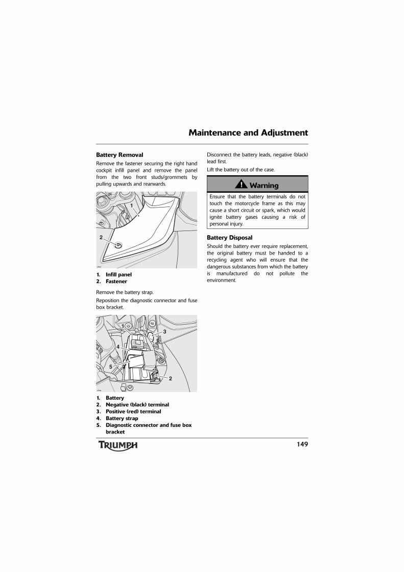
149
Maintenance and Adjustment
Battery RemovalRemove the fastener securing the right handcockpit infill panel and remove the panelfrom the two front studs/grommets bypulling upwards and rearwards.
1. Infill panel2. Fastener
Remove the battery strap.
Reposition the diagnostic connector and fusebox bracket.
1. Battery2. Negative (black) terminal3. Positive (red) terminal4. Battery strap5. Diagnostic connector and fuse box
bracket
Disconnect the battery leads, negative (black)lead first.
Lift the battery out of the case.
Battery DisposalShould the battery ever require replacement,the original battery must be handed to arecycling agent who will ensure that thedangerous substances from which the batteryis manufactured do not pollute theenvironment.
chtd
2
1
chte
2
31
4
5
WarningEnsure that the battery terminals do nottouch the motorcycle frame as this maycause a short circuit or spark, which wouldignite battery gases causing a risk ofpersonal injury.

150
Maintenance and Adjustment
Battery MaintenanceClean the battery using a clean, dry cloth. Besure that the cable connections are clean.
The battery is a sealed type and does notrequire any maintenance other than checkingthe Voltage and routine recharging whenrequired, such as during storage.
It is not possible to adjust the battery acidlevel in the battery; the sealing strip must notbe removed.
Battery Discharge
Under normal conditions, the motorcyclecharging system will keep the battery fullycharged. However, if the motorcycle isunused, the battery will gradually dischargedue to a normal process called self discharge;the clock, engine control module (ECM)memory, high ambient temperatures, or theaddition of electrical security systems or otherelectrical accessories will all increase this rateof battery discharge. Disconnecting thebattery from the motorcycle during storagewill reduce the rate of discharge.
WarningThe battery acid is corrosive and poisonousand will cause damage to unprotectedskin. Never swallow battery acid or allow itto come into contact with the skin. Toprevent injury, always wear eye and skinprotection when handling the battery.
CautionThe charge level in the battery must bemaintained to maximize battery life.
Failure to maintain the battery charge levelcould cause serious internal damage to thebattery.

151
Maintenance and Adjustment
Battery Maintenance During Storage and Infrequent Use of the MotorcycleDuring storage or infrequent use of themotorcycle, inspect the battery Voltageweekly using a digital multimeter. Follow themanufacturer's instructions supplied with themeter.
Should the battery Voltage fall below12.7 Volts, the battery should be charged(see page 151).
Allowing a battery to discharge or leaving itdischarged for even a short period of timecauses sulphation of the lead plates.Sulphation is a normal part of the chemicalreaction inside the battery, however over timethe sulphate can crystallize on the platesmaking recovery difficult or impossible. Thispermanent damage is not covered by themotorcycle warranty, as it is not due to amanufacturing defect.
Keeping the battery fully charged reduces thelikelihood of it freezing in cold conditions.Allowing a battery to freeze will cause seriousinternal damage to the battery.
Battery ChargingFor help with selecting a battery charger,checking the battery Voltage or batterycharging, contact your local authorizedTriumph dealer.
WarningThe battery gives off explosive gases; keepsparks, flames and cigarettes away. Provideadequate ventilation when charging orusing the battery in an enclosed space.
The battery contains sulphuric acid (batteryacid). Contact with skin or eyes may causesevere burns. Wear protective clothing anda face shield.
If battery acid gets on your skin, flush withwater immediately.
If battery acid gets in your eyes, flush withwater for at least 15 minutes and SEEKMEDICAL ATTENTION IMMEDIATELY.
If battery acid is swallowed, drink largequantities of water and SEEK MEDICALATTENTION IMMEDIATELY.
KEEP BATTERY ACID OUT OF THEREACH OF CHILDREN.

152
Maintenance and Adjustment
Should the battery Voltage fall below12.7 Volts, the battery should be chargedusing a Triumph approved battery charger.Always follow the instructions supplied withthe battery charger.
For extended periods of storage (beyond twoweeks) the battery should be removed fromthe motorcycle and kept charged using aTriumph approved maintenance charger.
Similarly, should the battery charge fall to alevel where it will not start the motorcycle,remove the battery from the motorcyclebefore charging.
Battery Installation
Place the battery in the battery case.
Reconnect the battery positive (red) lead.
Reconnect the negative (black) lead, notingthe orientation of the terminal, as shownbelow.
1. Battery negative terminal2. Negative lead
CautionDo not use an automotive quick charger asit may overcharge and may damage thebattery and the alternator.
WarningEnsure that the battery terminals do nottouch the motorcycle frame as this maycause a short circuit or spark, which wouldignite battery gases causing a risk ofpersonal injury.
1
2

153
Maintenance and Adjustment
Apply a light coat of grease to the terminalsto prevent corrosion.
Cover the positive terminal with theprotective cap.
Reposition the diagnostic connector and fusebox bracket.
Refit the battery strap, ensuring thediagnostic connector and fuse box bracket issecured by the strap.
Align the infill panel mounting studs to thegrommets and press down and forwards tosecure.
Align the infill panel to the cockpit and refitthe fastener, tightening to 27 lbf-in (3 Nm).
Trophy SE models only: After batteryreconnection allow the Triumph ElectronicSuspension (TES) system to re-calibrate asdescribed on page 57.
Fuse Boxes
Main Fuse Boxes
1. Front fuse box2. Rear fuse box3. ABS fuse box
The three fuse boxes are located beneath theleft hand side panel.
To allow access to the fuse boxes, the lefthand side panel must be removed (seepage 133).
The ABS fuse box is located next to the frontmain fuse box.
WarningAlways replace blown fuses with new onesof the correct rating (as specified on thefuse box cover) and never use a fuse ofhigher rating. Use of an incorrect fusecould lead to an electrical problem,resulting in motorcycle damage, loss ofmotorcycle control and an accident.
chsd
1
3
2Front of Motorcycle

154
Maintenance and Adjustment
Fuse IdentificationA blown fuse is indicated when all of thesystems protected by that fuse becomeinoperative. When checking for a blown fuse,use the tables to establish which fuse hasblown.
The fuse identification numbers listed in thetables correspond with those printed on thefuse box covers, as shown below. Spare fusesare located at right angles to the main fusesand should be replaced if used.
Fuse Layout - Trophy
1. Front fuse box cover2. Front fuse box3. Spare fuses
4. Rear fuse box5. Rear fuse box cover
Front Fuse Box Rear Fuse Box
10 102
1015
10
10
6
OP
EN
15A
5
20A4
10A
3
10A2
10A1
1015 20 15 20
1520
10
15
20A1 O
PE
N
15A2
20A3
10A4
15A5
10A6
10
12V
12V
12V
EMPTY
2
1
4
5
3cebw 3
Front of Motorcycle
Circuit Protected Position Rating (Amps)
Heated grips 1 10
Auxiliary socket 2 10
Empty 3 -
Auxiliary sockets 4 20
Auxiliary sockets 5 10
Windshield 6 15
Circuit Protected Position Rating (Amps)
Headlight 1 20
Engine management 2 15
Cooling fan 3 20
Fuel pump 4 10
Ignition, instruments 5 15
Tail light, brake light, horn
6 10

155
Maintenance and Adjustment
Fuse Layout - Trophy SE
1. Front fuse box cover2. Front fuse box3. Spare fuses
4. Rear fuse box5. Rear fuse box cover
Front Fuse Box Rear Fuse Box
10 152010
1015
10
10
6
OP
EN
15A
5
20A4
15A
3
10A2
10A1
1515 20 15 20
1520
10
15
20A1 O
PE
N
15A2
20A3
10A4
15A5
15A6
10
TES
12V
12V
10A
2
1
4
5
3cebw 3
Front of Motorcycle
Circuit Protected Position Rating (Amps)
Heated grips 1 10
Auxiliary socket 2 10
Audio system 3 10
Auxiliary sockets 4 20
Triumph Electronic Suspension (TES)
5 15
Windshield 6 15
Circuit Protected Position Rating (Amps)
Headlight 1 20
Engine management 2 15
Cooling fan 3 20
Fuel pump 4 10
Ignition, instruments 5 15
Tail light, brake light, horn
6 15

156
Maintenance and Adjustment
ABS Fuse Box
The ABS system is protected by two fuses,located in a separate fuse box next to thefront fuse box. The ABS fuse box alsocontains a spare 20 Amp fuse.
1. ABS fuse boxTo allow access to the ABS fuse box, the lefthand side panel must be removed (seepage 133).
Main FuseThe 40 Amp main fuse is located above thebattery.
To allow access to the main fuse, remove thefastener securing the right hand cockpit infillpanel and remove the panel from the twofront studs/grommets by pulling upwardsand rearwards.
1. Infill panel2. Fastener
1. Main fuse
Circuit Protected Position Rating (Amps)
ABS 1 20
ABS 2 20
chsd
1
Front of Motorcycle
chtd
2
1
chte
1

157
Maintenance and Adjustment
Headlights
Headlight AdjustmentVertical headlight adjustment is performedelectrically via the instruments, seeAdjustment on page 48. For horizontaladjustment consult you authorized Triumphdealer.
Headlight Bulb Replacement
Note:
• It is not necessary to remove theheadlight when bulb replacementbecomes necessary.
To Replace a Bulb:Disconnect the battery, negative (black) leadfirst (see page 148).
WarningAdjust road speed to suit the visibility andweather conditions in which the motorcycleis being operated.
Ensure that the beams are adjusted toilluminate the road surface sufficiently farahead without blinding oncoming traffic.An incorrectly adjusted headlight mayimpair visibility causing an accident.
CautionIf the motorcycle is to be used underclosed-course conditions, you may beasked to tape the visible outer surface ofthe headlight.
When taped, the headlight will overheatand distort the outer surface. Therefore, toavoid headlight distortion, alwaysdisconnect the headlights when they aretaped for use under closed-courseconditions.
WarningThe bulbs become hot during use. Alwaysallow sufficient time for the bulb to coolbefore handling. Avoid touching the glasspart of the bulb. If the glass is touched orgets dirty, clean with alcohol before reuse.
CautionThe use of non-approved headlight bulbsmay result in damage to the headlight lens.
Use a genuine Triumph supplied headlightbulb as specified in the Triumph PartsCatalog.
Always have replacement headlight bulbsinstalled by an authorized Triumph dealer.

158
Maintenance and Adjustment
Remove the two fasteners and remove thelower yoke cover to allow access to the bulbsfrom underneath.
1. Lower yoke cover2. Fasteners
Remove the bulb cover from the bulb to bereplaced.
Disconnect the multi-plug from the bulb.
Detach the bulb retainer from the hook onthe headlight assembly and rotate it awayfrom the bulb as shown.
1. Bulb retainer (right hand shown)2. Bulb retainer hook3. Bulb
Remove the bulb from the headlight.
Installation is the reverse of the removalprocedure, noting the following:
• Tighten the lower yoke cover fasteners to27 lbf-in (3 Nm).
• Reconnect the battery, positive (red) leadfirst (see page 148).
chtk
1
2
chsf
1
2
3

159
Maintenance and Adjustment
Position Light Bulb Replacement
1. Position light bulbThe position light is fitted to the underside ofthe headlight, behind the headlight trimpanel.
To Replace the Bulb:Disconnect the battery, negative (black) leadfirst (see page 148).
Remove the two fasteners and detach theheadlight trim panel (located below theheadlight) by sliding it forwards.
Disconnect the ambient air temperaturesensor connector and remove the trim panel.
1. Headlight trim panel2. Fasteners3. Removal direction4. Ambient air temperature sensor
location
Rotate the bulb holder anti-clockwise torelease it.
Replace the bulb.
Installation is the reverse of the removalprocedure, noting the following:
• Reconnect the ambient air temperaturesensor connector.
• Refit the headlight trim panel, ensuringthe hooks on the panel engage in theslots on the underside of the headlight.Tighten the fasteners to 27 lbf-in (3 Nm).
• Reconnect the battery, positive (red) leadfirst (see page 148).
chtc
1
chtu
2
21
3
4

160
Maintenance and Adjustment
Brake/Tail Light AssemblyThe brake/tail light, license plate light andrear direction turn signals are incorporated ina single assembly.
The brake/tail light unit is a sealed,maintenance free LED unit. The directionturn signal bulbs and license plate light bulbcan be replaced as described below:
Brake/Tail Light Assembly Removal and Installation
1. R-clip2. Wing nut
Remove the rear seat (see page 76).
Remove the R-clip and wing nut and detachthe brake/tail light assembly.
Installation is the reverse of the removalprocedure, noting the following:
• Tighten the plastic nut to 11.25 lbf-in(1.25 Nm).
Bulb Replacement
1. Turn signal bulb holders2. License plate light bulb holder3. Outer studs
Rear Direction Turn Signal Bulb ReplacementRotate the bulb holder connector away fromthe outer stud to release it.
Replace the bulb.
Insert the bulb holder to the brake/tail lightunit and rotate towards the outer stud tosecure in the brake/tail light assembly.
License Plate Light Bulb ReplacementCarefully pull the bulb holder from the backof the license plate light unit and remove thebulb.
Installation is the reverse of the removalprocedure.
chsw
1
2
chtj
2
1 1
chtj
3 3

161
Maintenance and Adjustment
Front Direction Indicator Bulb Replacement
1. Rear view mirror2. Indicator bulb holder
Fold out the rear view mirror towards the rearof the motorcycle.
Rotate the right hand bulb holderanti-clockwise to release it.
Rotate the left hand bulb holder clockwise torelease it.
Replace the bulb.
Installation is the reverse of the removalprocedure.
CleaningFrequent, regular cleaning is an essential partof the maintenance of your motorcycle. Ifregularly cleaned, the appearance will bepreserved for many years. Cleaning with coldwater containing an automotive cleaner isessential at all times but particularly so afterexposure to sea breezes, sea water, dusty ormuddy roads and in winter when roads aretreated for ice and snow. Do not usehousehold detergent, as the use of suchproducts will lead to premature corrosion.
Although, under the terms of yourmotorcycle warranty, cover is providedagainst the corrosion of certain items, theowner is expected to observe this reasonableadvice which will safeguard against corrosionand enhance the appearance of themotorcycle.
chso
1
2

162
Maintenance and Adjustment
Preparation for WashingBefore washing, precautions must be takento keep water off the following places.
Rear opening of the exhausts: Cover with aplastic bag secured with rubber bands.
Clutch and brake levers, switch housings onthe handlebar: Cover with plastic bags.
Ignition switch and steering lock: Cover thekeyhole with tape.
Remove any items of jewelry such as rings,watches, zips or belt buckles, which mayscratch or otherwise damage painted orpolished surfaces.
Use separate cleaning sponges or cleaningcloths for washing painted/polished surfacesand chassis areas. Chassis areas (such aswheels and under fenders) will be exposed tomore abrasive road grime and dust, whichmay then scratch painted or polishedsurfaces, if the same sponge or cleaningcloths are used.
Where to be CarefulAvoid spraying water with any great forcenear the following places:
• Instruments;
• Brake cylinders and brake calipers;
• Steering head bearings.
Note:
• Use of soaps that are highly alkalinewill leave a residue on paintedsurfaces, and may also cause waterspotting. Always use a low alkalinesoap to aid the cleaning process.
CautionAny water sprayed around the air intakeduct could enter the airbox and engine,causing damage to both items.
CautionUse of high-pressure spray washers is notrecommended. When using pressurewashers, water may be forced intobearings and other components causingpremature wear from corrosion and loss oflubrication.

163
Maintenance and Adjustment
After WashingRemove the plastic bags and tape, and clearthe air intakes.
Test the brakes before motorcycle operation.
Start the engine and run it for 5 minutes.Ensure adequate ventilation for the exhaustfumes.
Use a dry cloth to absorb water residue. Donot allow water to stand on the machine asthis will lead to corrosion.
Seat Care
To help maintain its appearance, clean theseat using a sponge or cleaning cloth withsoap and water.
Unpainted Aluminum ItemsItems such as brake and clutch levers, wheels,engine covers, top and bottom yokes onsome models must be correctly cleaned topreserve their appearance. Please contactyour dealer if you are unsure whichcomponents on your motorcycle areunpainted aluminum parts.
Use a proprietary brand of aluminum cleaner.
Clean aluminum items regularly, in particularafter use in inclement weather, where thecomponents must be hand washed and driedeach time the machine is used.
Warranty claims due to inadequatemaintenance will not be allowed.
WarningNever wax or lubricate the brake discs.Loss of braking power and an accidentcould result. Clean the disc with aproprietary brand of oil-free brake disccleaner.
CautionUse of chemicals or high-pressure spraywashers is not recommended for cleaningthe seat. Using chemicals or pressurewashers may damage the seat cover.

164
Maintenance and Adjustment
Windshield Cleaning
Clean the windshield with a solution of mildsoap or detergent and lukewarm water. Aftercleaning, rinse well and then dry with a soft,lint free cloth.
If the transparency of the windshield isreduced by scratches or oxidation whichcannot be removed, the windshield must bereplaced.
CautionProducts such as window cleaning fluids,insect remover, rain repellent, scouringcompounds, gasoline or strong solventssuch as alcohol, acetone, carbontetrachloride, etc. will damage thewindshield. Never allow these products tocontact the screen.
WarningNever attempt to clean the windshieldwhile the motorcycle is in motion asreleasing the handlebars may cause loss ofvehicle control and an accident.
Operation of the motorcycle with adamaged or scratched windshield willreduce the rider's forward vision. Any suchreduction in forward vision is dangerousand may lead to an accident causing injuryor death.
CautionCorrosive chemicals such as battery acidwill damage the windshield. Never allowcorrosive chemicals to contact thewindshield.

165
Maintenance and Adjustment
Cleaning of the Exhaust SystemAll parts of the exhaust system of yourmotorcycle must be cleaned regularly toavoid a deterioration of its appearance.
Note:
• The exhaust system must be coolbefore washing to prevent waterspotting.
WashingPrepare a mixture of cold water and mildautomotive cleaner. Do not use a highlyalkaline soap as commonly found atcommercial car washes because it leaves aresidue.
Wash the exhaust system with a soft cloth. Donot use an abrasive scouring pad or steelwool. They will damage the finish.
Rinse the exhaust system thoroughly.
Ensure no soap or water enters the mufflers.
DryingDry the exhaust system as far as possible witha soft cloth. Do not run the engine to dry thesystem or spotting will occur.
ProtectingWhen the exhaust system is dry, rub'Motorex 645 Clean and Protect' into thesurface.
It is recommended that regular protection beapplied to the system as this will both protectand enhance the system's appearance.
CautionThe use of abrasive cleaners and polisheswill damage the system and must not beused.

Maintenance and Adjustment
166
This page intentionally left blank

167
Storage
STORAGE
Preparation For StorageClean and dry the entire vehicle thoroughly.
Fill the fuel tank with the correct grade ofunleaded fuel and add a fuel stabilizer (ifavailable), following the fuel stabilizermanufacturer's instructions.
Remove the spark plug from each cylinderand put several drops (5 ml) of engine oil intoeach cylinder. Cover the spark plug holeswith a piece of cloth or rag. With the enginestop switch in the RUN position, push thestarter button for a few seconds to coat thecylinder walls with oil. Install the spark plugs,tightening to 9 lbf-ft (12 Nm).
Change the engine oil and filter (seepage 125).
Check and if necessary correct the tirepressures (see page 173).
Set the motorcycle on a stand so that bothwheels are raised off the ground. (If thiscannot be done, put boards under the frontand rear wheels to keep dampness awayfrom the tires.)
Spray rust inhibiting oil (there are a host ofproducts on the market and your dealer willbe able to offer you local advice) on allunpainted metal surfaces to prevent rusting.Prevent oil from getting on rubber parts,brake discs or in the brake calipers.
Make sure the cooling system is filled with a50% mixture of coolant (noting thatHD4X Hybrid OAT coolant, as supplied byTriumph, is pre-mixed and requires nodilution) and distilled water solution (seepage 127).
Remove the battery, and store it where it willnot be exposed to direct sunlight, moisture,or freezing temperatures. During storage itshould be given a slow charge (one ampereor less) about once every two weeks (seepage 148).
Store the motorcycle in a cool, dry area, awayfrom sunlight, and with a minimum dailytemperature variation.
Put a suitable porous cover over themotorcycle to keep dust and dirt fromcollecting on it. Avoid using plastic or similarnon-breathable, coated materials that restrictair flow and allow heat and moisture toaccumulate.
WarningGasoline is extremely flammable and canbe explosive under certain conditions. Turnthe ignition switch off. Do not smoke.Make sure the area is well ventilated andfree from any source of flame or sparks;this includes any appliance with a pilotlight.

168
Storage
Preparation After StorageInstall the battery (if removed) (seepage 152).
If the motorcycle has been stored for morethan four months, change the engine oil (seepage 125).
Check all the points listed in the Daily SafetyChecks section.
Before starting the engine, remove the sparkplugs from each cylinder.
Put the side stand down.
Crank the engine on the starter motor severaltimes until the oil pressure light goes out.
Replace the spark plugs, tightening to9 lbf-ft (12 Nm), and start the engine.
Check and if necessary correct the tirepressures (see page 173).
Clean the entire vehicle thoroughly.
Check the brakes for correct operation.
Test ride the motorcycle at low speeds.

Specifications
169
SPECIFICATIONS
Dimensions
Overall Length . . . . . . . . . . . . . . . . . . . . . 88 in (2235 mm)
Overall Width . . . . . . . . . . . . . . . . . . . . . . 38.3 in (975 mm) (with panniers fitted)
37.6 in (955 mm) (without panniers)
Overall Height. . . . . . . . . . . . . . . . . . . . . . 56.5 in (1435 mm) (screen fully down)
61.2 in (1555 mm) (screen fully up)
Wheelbase. . . . . . . . . . . . . . . . . . . . . . . . . 60.7 in (1542 mm)
Seat Height . . . . . . . . . . . . . . . . . . . . . . . . 31.4 in (800 mm) (low setting)*
32.3 in (820 mm) (high setting)*
*North American and Canadian markets have a 1.2 in (30 mm) lower seat fitted.
Weights
Wet Weight . . . . . . . . . . . . . . . . . . . . . . . . 633 lbs (301 kg)
Maximum Payload . . . . . . . . . . . . . . . . . . 526 lbs (239 kg)
Engine
Type . . . . . . . . . . . . . . . . . . . . . . . . . . . . . . In-line 3 cylinder
Displacement. . . . . . . . . . . . . . . . . . . . . . . 74.14 cu in (1215 cc)
Bore x Stroke . . . . . . . . . . . . . . . . . . . . . . 3.4 x 2.8 in (85 x 71.4 mm)
Compression Ratio . . . . . . . . . . . . . . . . . . 11:1
Cylinder Numbering. . . . . . . . . . . . . . . . . Left to Right
Cylinder Sequence . . . . . . . . . . . . . . . . . . 1 at left
Firing Order . . . . . . . . . . . . . . . . . . . . . . . 1-2-3
Starting System . . . . . . . . . . . . . . . . . . . . . Electric Starter

Specifications
170
Performance
Maximum Power (95/1/EC) . . . . . . . . . . . 132 bhp (98.5 kW/134 PS) at 8,900 rpm
Maximum Torque . . . . . . . . . . . . . . . . . . . 88.5 lbf-ft (120 Nm) at 6,450 rpm
Lubrication
Lubrication. . . . . . . . . . . . . . . . . . . . . . . . . Pressure Lubrication (wetsump)
Engine Oil Capacities
Dry Fill . . . . . . . . . . . . . . . . . . . . . . . . . . . . 1.9 US gallons (4.5 liters)
Oil/Filter Change . . . . . . . . . . . . . . . . . . . 1.1 US gallons (4.0 liters)
Oil Change Only. . . . . . . . . . . . . . . . . . . . 1.0 US gallon (3.85 liters)
Cooling
Coolant Type . . . . . . . . . . . . . . . . . . . . . . . Triumph HD4X Hybrid OAT coolant
Water/Anti-freeze ratio . . . . . . . . . . . . . . . 50/50 (premixed as supplied by Triumph)
Coolant Capacity . . . . . . . . . . . . . . . . . . . . 0.74 US gallons (2.8 liters)
Thermostat Opens (nominal) . . . . . . . . . 190°F (88°C) (nominal)

Specifications
171
Fuel System
Type . . . . . . . . . . . . . . . . . . . . . . . . . . . . . . Electronic Fuel Injection
Injectors . . . . . . . . . . . . . . . . . . . . . . . . . . . Solenoid Operated
Fuel Pump . . . . . . . . . . . . . . . . . . . . . . . . . Submerged Electric
Fuel Pressure (nominal). . . . . . . . . . . . . . . 50.7 PSI (3.5 bar)
Fuel
Type . . . . . . . . . . . . . . . . . . . . . . . . . . . . . . 91 RON unleaded
Tank Capacity . . . . . . . . . . . . . . . . . . . . . . (motorcycle upright)
6.6 US gallons (25.0 liters)
Ignition
Ignition System . . . . . . . . . . . . . . . . . . . . . Digital Inductive
Electronic Rev Limiter . . . . . . . . . . . . . . . . 9,500 r/min
Spark Plug . . . . . . . . . . . . . . . . . . . . . . . . . NGK CR8EK
Spark Plug Gap. . . . . . . . . . . . . . . . . . . . . 0.026 in (0.7 mm)
Gap Tolerance . . . . . . . . . . . . . . . . . . . . . . +0.001/-0.002 in (+0.05/-0.1 mm)

Specifications
172
Transmission
Transmission Type . . . . . . . . . . . . . . . . . . . 6 Speed, Constant Mesh
Clutch Type . . . . . . . . . . . . . . . . . . . . . . . . Wet, Multi-Plate
Final Drive Ratio . . . . . . . . . . . . . . . . . . . . 2.557:1
Gear Ratios:
Front Bevel Box . . . . . . . . . . . . . . . . . . . . . 1.042:1 (24/25)
Rear Bevel Box . . . . . . . . . . . . . . . . . . . . . 2.455:1 (11/27)
1st. . . . . . . . . . . . . . . . . . . . . . . . . . . . . . . . 2.846:1 (13/37)
2nd . . . . . . . . . . . . . . . . . . . . . . . . . . . . . . . 2.056:1 (18/37)
3rd . . . . . . . . . . . . . . . . . . . . . . . . . . . . . . . 1.583:1 (24/38)
4th . . . . . . . . . . . . . . . . . . . . . . . . . . . . . . . 1.292:1 (24/31)
5th . . . . . . . . . . . . . . . . . . . . . . . . . . . . . . . 1.138:1 (29/33)
6th . . . . . . . . . . . . . . . . . . . . . . . . . . . . . . . 0.964:1 (28/27)

Specifications
173
Tires
Tire Sizes:
Front Size. . . . . . . . . . . . . . . . . . . . . . . . . . 120/70 ZR17
Rear Size . . . . . . . . . . . . . . . . . . . . . . . . . . 190/55 ZR17
Tire Pressures (Cold):
Front . . . . . . . . . . . . . . . . . . . . . . . . . . . . . 36 lb/in² (2.5 bar)
Rear . . . . . . . . . . . . . . . . . . . . . . . . . . . . . . 42 lb/in² (2.9 bar)
WarningUse the recommended tires ONLY in the combinations given. Do not mix tires from differentmanufacturers or mix different specification tires from the same manufacturers as this mayresult in loss of motorcycle control and an accident.
Approved Road Tires
Option 1, Front . . . . . . . . . . . . . . . . . . . . . Pirelli Angel ST - A specification
Option 1, Rear . . . . . . . . . . . . . . . . . . . . . . Pirelli Angel ST - Standard specification
Option 2, Front . . . . . . . . . . . . . . . . . . . . . Metzeler Roadtec Z8 Interact - Standard specification
Option 2, Rear . . . . . . . . . . . . . . . . . . . . . Metzeler Roadtec Z8 Interact - C specification
Option 3, Front . . . . . . . . . . . . . . . . . . . . . Dunlop Roadsmart - Standard specification
Option 3, Rear . . . . . . . . . . . . . . . . . . . . . Dunlop Roadsmart - K specification
Option 4, Front . . . . . . . . . . . . . . . . . . . . . Dunlop Roadsmart II - Standard specification
Option 4, Rear . . . . . . . . . . . . . . . . . . . . . Dunlop Roadsmart II - Standard specification
Note:
• For all tires without a letter specification (such as option 1, rear above), use thestandard specification tire from the manufacturer.

Specifications
174
Electrical Equipment
Battery Type. . . . . . . . . . . . . . . . . . . . . . . . YTX20L-BS
Battery Rating . . . . . . . . . . . . . . . . . . . . . . 12 Volt, 18 Ah
Alternator. . . . . . . . . . . . . . . . . . . . . . . . . . 12 Volt, 70 Amp at 4,000 rpm
Headlight . . . . . . . . . . . . . . . . . . . . . . . . . . 2 x 12 Volt, 55/60 Watt, H4 Halogen
Tail/Brake Light . . . . . . . . . . . . . . . . . . . . . LED
Parking light . . . . . . . . . . . . . . . . . . . . . . . 12 Volt, 5 Watt
Directional Indicator Lights . . . . . . . . . . . . 12 Volt, 10 Watt, amber
Frame
Rake. . . . . . . . . . . . . . . . . . . . . . . . . . . . . . 27°
Trail . . . . . . . . . . . . . . . . . . . . . . . . . . . . . . 4.7 in (119 mm)

Specifications
175
Tightening Torques
Oil Filter . . . . . . . . . . . . . . . . . . . . . . . . . . . 7 lbf-ft (10 Nm)
Oil Drain Plug . . . . . . . . . . . . . . . . . . . . . . 18 lbf-ft (25 Nm)
Spark Plug . . . . . . . . . . . . . . . . . . . . . . . . . 9 lbf-ft (12 Nm)
Rear Wheel Nuts. . . . . . . . . . . . . . . . . . . . 52 lbf-ft (70 Nm)
Fluids and Lubricants
Engine Oil . . . . . . . . . . . . . . . . . . . . . . . . . Semi or fully synthetic 10W/40 or 10W/50 motorcycle engine oil which meets specification API SH (or higher) and JASO MA, such as Castrol Power 1 Racing 4T 10W-40 (fully synthetic)
Brake and Clutch Fluid . . . . . . . . . . . . . . . DOT 4 Brake and Clutch Fluid
Coolant . . . . . . . . . . . . . . . . . . . . . . . . . . . Triumph HD4X Hybrid OAT coolant
Bearings and Pivots . . . . . . . . . . . . . . . . . . Grease to NLGI 2 specification
Final Drive Unit . . . . . . . . . . . . . . . . . . . . . Castrol SAF-XO (fully synthetic hypoid oil)

Specifications
176
This page intentionally left blank

177
Index
INDEX
AAccessories and Loading . . . . . . . . . . . . . 111
Loading Distribution . . . . . . . . . . . . . 115Maximum Vehicle Loading Weight . . . . . . . . . . . . . . . . . . . . . . . . 111
Accessory D-lock Storage . . . . . . . . . . . . . . 79Audio System Handbook . . . . . . . . . . . . . . 75
BBattery . . . . . . . . . . . . . . . . . . . . . . . . . . . . 148
Charging . . . . . . . . . . . . . . . . . . . . . . 151Disposal . . . . . . . . . . . . . . . . . . . . . . . 149Installation . . . . . . . . . . . . . . . . . . . . . 152Maintenance . . . . . . . . . . . . . . . . . . . 150Removal . . . . . . . . . . . . . . . . . . . . . . . 149
Brake/Tail Light AssemblyBrake/Tail Light/License Plate Light . . . . . . . . . . . . . . . . . . . . . . . . . . 160Direction Turn Signal Lights . . . . . . . 160
Brakes . . . . . . . . . . . . . . . . . . . . . . . . . . . . 133Brake and Clutch Lever Adjusters . . . 73Braking. . . . . . . . . . . . . . . . . . . . . . . . 103Disc Brake Fluid . . . . . . . . . . . . . . . . . 135Light Switches . . . . . . . . . . . . . . . . . . 137Pad Wear Compensation . . . . . . . . . 134Wear Inspection. . . . . . . . . . . . . . . . . 133
Breaking-In . . . . . . . . . . . . . . . . . . . . . . . . . 95Breaking-in New Brake Pads and Discs . . 133
CCleaning . . . . . . . . . . . . . . . . . . . . . . . . . . 161
After Washing . . . . . . . . . . . . . . . . . . 163Drying . . . . . . . . . . . . . . . . . . . . . . . . 165Exhaust System . . . . . . . . . . . . . . . . . 165Preparation. . . . . . . . . . . . . . . . . . . . . 162Protecting. . . . . . . . . . . . . . . . . . . . . . 165Unpainted Aluminum Items . . . . . . . 163Washing. . . . . . . . . . . . . . . . . . . . . . . 165Where to be Careful . . . . . . . . . . . . . 162
Clutch . . . . . . . . . . . . . . . . . . . . . . . . . . . . 131Clutch Fluid Level Inspection and Adjustment. . . . . . . . . . . . . . . . . . . . . 131
Cockpit Stowage Box . . . . . . . . . . . . . . . . 80Considerations for High-Speed Operation . . . . . . . . . . . . . . . . . . . . . . . . . 108Cooling System . . . . . . . . . . . . . . . . . . . . . 127
Coolant Change. . . . . . . . . . . . . . . . . 130Coolant Level Adjustment . . . . . . . . . 129Coolant Level Inspection . . . . . . . . . . 128Corrosion Inhibitors . . . . . . . . . . . . . . 127
Cruise Control . . . . . . . . . . . . . . . . . . . . . . 58Activating . . . . . . . . . . . . . . . . . . . . . . 59Deactivating . . . . . . . . . . . . . . . . . . . . 60Decreasing Speed . . . . . . . . . . . . . . . 62Increasing Speed . . . . . . . . . . . . . . . . . 61Resuming . . . . . . . . . . . . . . . . . . . . . . . 61
EElectrical Accessory Sockets . . . . . . . . . . . 83Engine
Serial Number . . . . . . . . . . . . . . . . . . . 17To Start the Engine . . . . . . . . . . . . . . 100To Stop the Engine . . . . . . . . . . . . . . 100
Engine Oil . . . . . . . . . . . . . . . . . . . . . . . . . 124Disposal of Oil and Filters . . . . . . . . . 126Grade and Specification. . . . . . . . . . . 127Oil and Oil Filter Change . . . . . . . . . 125Oil Level Inspection . . . . . . . . . . . . . . 124
FFinal Drive Unit
Oil Level Adjustment . . . . . . . . . . . . . 132Front Suspension. . . . . . . . . . . . . . . . . . . . 139
Fork Inspection. . . . . . . . . . . . . . . . . . 139Front Suspension Adjustment (Trophy only) . . . . . . . . . . . . . . . . . . . 140Front Suspension Settings Chart (Trophy only) . . . . . . . . . . . . . . . . . . . 140

178
Index
Fuel Requirement . . . . . . . . . . . . . . . . . . . . 70Filling the Fuel Tank . . . . . . . . . . . . . . 72Fuel Grade . . . . . . . . . . . . . . . . . . . . . . 70Fuel Tank Cap . . . . . . . . . . . . . . . . . . . 71
Fuse Boxes . . . . . . . . . . . . . . . . . . . . . . . . 153
GGears
Shifting Gears . . . . . . . . . . . . . . . . . . 102
HHazard Warning Lights . . . . . . . . . . . . . . . 68Headlights . . . . . . . . . . . . . . . . . . . . . . . . . 157
Adjustment . . . . . . . . . . . . . . . . . . . . 157Bulb Replacement . . . . . . . . . . . . . . . 157
Heated Grips. . . . . . . . . . . . . . . . . . . . . . . . 80Helmet and Luggage Hooks . . . . . . . . . . . 82
Helmet Hooks . . . . . . . . . . . . . . . . . . . 82Luggage Straps and Hooks. . . . . . . . . 82
IIgnition
Key . . . . . . . . . . . . . . . . . . . . . . . . . . . . 62Switch/Steering Lock . . . . . . . . . . . . . . 63
Instrument PanelInstrument Panel Layout . . . . . . . . . . . 23Multi-function Display Screen . . . . . . . 25Multi-function Display Screen Layout . . . . . . . . . . . . . . . . . . . . . . . . . 24Speedometer . . . . . . . . . . . . . . . . . . . . 25Tachometer . . . . . . . . . . . . . . . . . . . . . 25Warning Lights . . . . . . . . . . . . . . . . . . 26
InstrumentsAutomatic Self Cancelling Turn Signals. . . . . . . . . . . . . . . . . . . . . 51Central Display Area . . . . . . . . . . . . . . 40
Adjustment Menu . . . . . . . . . . . . 45Bike Setup. . . . . . . . . . . . . . . . . . . 48Profiles . . . . . . . . . . . . . . . . . . . . . 44Settings Menu . . . . . . . . . . . . . . . 43Trip Computer 1 and 2 . . . . . . . . 40
Trip Computer Reset . . . . . . . . . 43Trip Setup . . . . . . . . . . . . . . . . . . 47
Lower Message Area . . . . . . . . . . . . . 50Audio Information. . . . . . . . . . . . . 51Cruise Control Status . . . . . . . . . . 51Information Messages. . . . . . . . . 50TPMS Information. . . . . . . . . . . . . 51Warning Messages . . . . . . . . . . . 50
Multi-function Display Screen . . . . . . 34Ambient Air Temperature . . . . . 34Clock . . . . . . . . . . . . . . . . . . . . . . 34Coolant Temperature Gauge . . . 35Fuel Gauge . . . . . . . . . . . . . . . . . 36Gear Position Display . . . . . . . . . 35Heated Grips. . . . . . . . . . . . . . . . 38Heated Seats . . . . . . . . . . . . . . . . 37Low Battery Warning . . . . . . . . . 39Service Interval Indicator. . . . . . . 38
Units of Measure . . . . . . . . . . . . . . . . 52
LLeft Handlebar Switches . . . . . . . . . . . . . . 66
Direction Indicator Switch . . . . . . . . . 67Headlight Dimmer Switch . . . . . . . . . 66Horn Button . . . . . . . . . . . . . . . . . . . . 67Instrument Scroll Button . . . . . . . . . . 67Instrument Select Button . . . . . . . . . . 67Pass Button. . . . . . . . . . . . . . . . . . . . . 67
Luggage System . . . . . . . . . . . . . . . . . . . . 86Pannier Installation . . . . . . . . . . . . . . . 87Pannier Operation . . . . . . . . . . . . . . . 88Pannier Removal . . . . . . . . . . . . . . . . 87Top Box Installation . . . . . . . . . . . . . . . 91Top Box Operation . . . . . . . . . . . . . . 93Top Box Removal . . . . . . . . . . . . . . . 90
MMotorcycle Storage
Preparation After Storage . . . . . . . . . 168Preparation For Storage . . . . . . . . . . . 167

179
Index
OOwner’s Literature . . . . . . . . . . . . . . . . . . . 75
PParking . . . . . . . . . . . . . . . . . . . . . . . . . . . 107Parts Identification. . . . . . . . . . . . . . . . . . . . 14
RRear Suspension . . . . . . . . . . . . . . . . . . . . 141
Rear Suspension Settings Chart (Trophy only) . . . . . . . . . . . . . . . . . . . 142
Rear Suspension AdjustmentRebound Damping (Trophy only). . . 142Spring Pre-Load. . . . . . . . . . . . . . . . . 141
Right Handlebar Switches . . . . . . . . . . . . . 65Cruise Control Adjust Button . . . . . . . 65Cruise Control ON/OFF button . . . . . 65Engine Stop Switch . . . . . . . . . . . . . . . 65Starter Button. . . . . . . . . . . . . . . . . . . . 65
SSafety . . . . . . . . . . . . . . . . . . . . . . . . . . . . . . 5
Daily Checks . . . . . . . . . . . . . . . . . . . . 96Fuel and Exhaust Fumes . . . . . . . . . . . . 6Handlebars and Footrests . . . . . . . . . . 11Maintenance/Equipment. . . . . . . . . . . . 8Motorcycle . . . . . . . . . . . . . . . . . . . . . . . 5Parking. . . . . . . . . . . . . . . . . . . . . . . . . . 7Parts and Accessories . . . . . . . . . . . . . . 8Riding. . . . . . . . . . . . . . . . . . . . . . . . . . . 9Safety Helmet and Clothing . . . . . . . . . 7
Seats . . . . . . . . . . . . . . . . . . . . . . . . . . . . . . 75Heated Seats . . . . . . . . . . . . . . . . . . . . 78Rear Seat . . . . . . . . . . . . . . . . . . . . . . . 76Rider’s Seat . . . . . . . . . . . . . . . . . . . . . 77Rider’s Seat Height Adjustment . . . . . 78Seat Care . . . . . . . . . . . . . . . . . . . . . . . 75
SpecificationsApproved Tire Options . . . . . . . . . . . 173Cooling . . . . . . . . . . . . . . . . . . . . . . . 170Dimensions . . . . . . . . . . . . . . . . . . . . 169Electrical Equipment . . . . . . . . . . . . . 174
Engine . . . . . . . . . . . . . . . . . . . . . . . . 169Engine Oil Capacities . . . . . . . . . . . . . 170Fluids and Lubricants . . . . . . . . . . . . . 175Frame . . . . . . . . . . . . . . . . . . . . . . . . . 174Fuel . . . . . . . . . . . . . . . . . . . . . . . . . . . 171Fuel System . . . . . . . . . . . . . . . . . . . . 171Ignition . . . . . . . . . . . . . . . . . . . . . . . . 171Lubrication . . . . . . . . . . . . . . . . . . . . . 170Performance . . . . . . . . . . . . . . . . . . . . 170Tightening Torques . . . . . . . . . . . . . . 175Tires . . . . . . . . . . . . . . . . . . . . . . . . . . 173Transmission . . . . . . . . . . . . . . . . . . . 172Weights . . . . . . . . . . . . . . . . . . . . . . . 169
Stands . . . . . . . . . . . . . . . . . . . . . . . . . . . . 74Center Stand . . . . . . . . . . . . . . . . . . . 74Side Stand . . . . . . . . . . . . . . . . . . . . . 74
Steering/Wheel Bearings . . . . . . . . . . . . . 137Inspection . . . . . . . . . . . . . . . . . . . . . . 138
TThrottle Control. . . . . . . . . . . . . . . . . . . . . 131
Inspection . . . . . . . . . . . . . . . . . . . . . . 131Throttle Control. . . . . . . . . . . . . . . . . . . . . 69Tire Pressure Monitoring System (TPMS)
Replacement Tires . . . . . . . . . . . . . . . 55Sensor Batteries . . . . . . . . . . . . . . . . . 54System Display . . . . . . . . . . . . . . . . . . 54Tire Pressures . . . . . . . . . . . . . . . . . . . 55TPMS symbol. . . . . . . . . . . . . . . . . . . 54
Tires . . . . . . . . . . . . . . . . . . . . . . . . . . . . . . 143Minimum Recommended Tread Depth . . . . . . . . . . . . . . . . . . . . 145Tire Inflation Pressures. . . . . . . . . . . . 144Tire Replacement . . . . . . . . . . . . . . . . 146Tire Wear . . . . . . . . . . . . . . . . . . . . . . 145
Tool Kit . . . . . . . . . . . . . . . . . . . . . . . . . . . 75TPMS Sensor ID Number. . . . . . . . . . . . . 53Triumph Electronic Suspension (TES). . . . 56Triumph Traction Control (TTC). . . . . . . . 55

180
Index
UUnder-seat Stowage Box . . . . . . . . . . . . . . 81
VVehicle Identification Number . . . . . . . . . . 17
WWarning Lights . . . . . . . . . . . . . . . . . . . . . 26Warnings
Warning Label Locations . . . . . . . . . . . 12Warning Labels . . . . . . . . . . . . . . . . . . 2Warnings, Cautions and Notes . . . . . . 1
Windshield. . . . . . . . . . . . . . . . . . . . . . . . . 84Windshield and Heated Grips Switch Unit . . . . . . . . . . . . . . . . . . . . . . . . 68Windshield Cleaning. . . . . . . . . . . . . . . . . 164