vhf/uhf antennas antenna training..pdfdipole antenna is equal to a half-wavelength at the frequency...
TRANSCRIPT

VHF/UHF ANTENNAS
By K5MJD
Mike Durbin PhD. E.E.

ANTENNAS A device that matches 377 ohm to your feed line!!
• FUN STUFF
A 70-meter dish antenna. Part of NASA's Jet Propulsion Laboratory (JPL) communication system.
In 1913, the Eiffel Tower was used an antenna. Back when communication was at very low frequencies, the antennas had to be very large to get any sort of radiation. The Eiffel Tower fit this bill well, and was used to communicate with the United States Naval Observatory in Arlington, Virginia.

EIRP DISCUSSION
EIRP is Effective Isotropic Radiated Power, also called the Equivalent Isotropic Radiated Power. In antenna measurements, the measured radiated power in a single direction.
As an example, suppose the radiated power is measured for an arbitrary antenna. Suppose the peak power is measured at is EIRP = 20 dBm = -10 dB = [0.1 W = 100 mW]. Then a perfectly isotropic antenna radiating 20 dBm would radiate equally poorly in all directions.
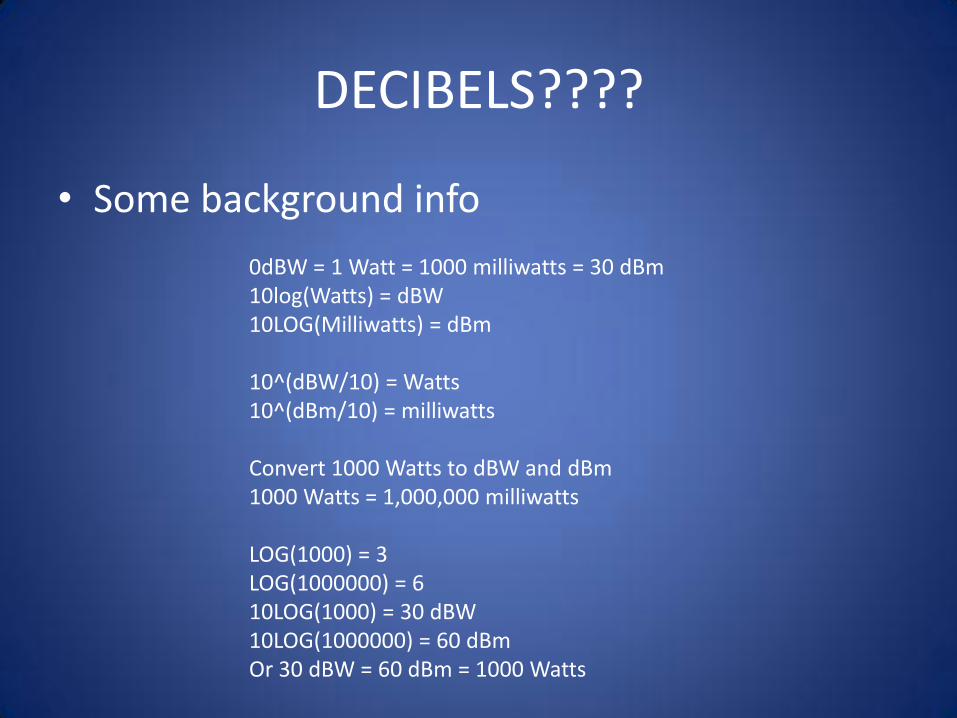
DECIBELS????
• Some background info
0dBW = 1 Watt = 1000 milliwatts = 30 dBm 10log(Watts) = dBW 10LOG(Milliwatts) = dBm 10^(dBW/10) = Watts 10^(dBm/10) = milliwatts Convert 1000 Watts to dBW and dBm 1000 Watts = 1,000,000 milliwatts LOG(1000) = 3 LOG(1000000) = 6 10LOG(1000) = 30 dBW 10LOG(1000000) = 60 dBm Or 30 dBW = 60 dBm = 1000 Watts
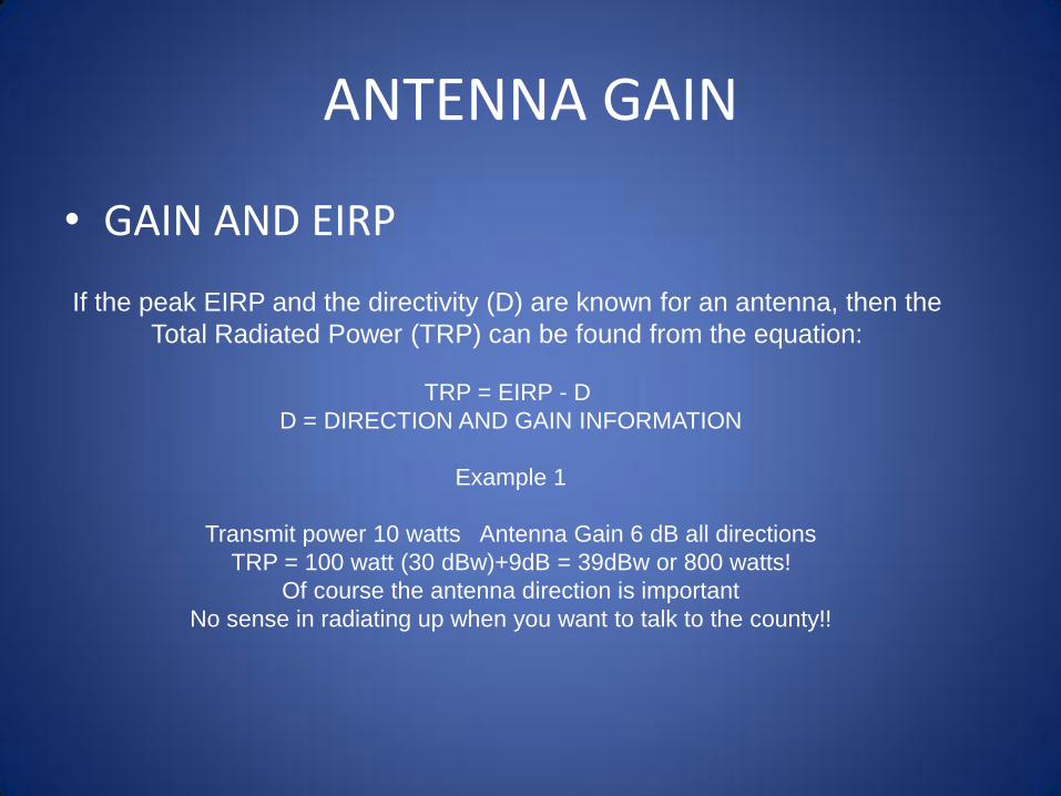
ANTENNA GAIN
• GAIN AND EIRP
If the peak EIRP and the directivity (D) are known for an antenna, then the
Total Radiated Power (TRP) can be found from the equation:
TRP = EIRP - D
D = DIRECTION AND GAIN INFORMATION
Example 1
Transmit power 10 watts Antenna Gain 6 dB all directions
TRP = 100 watt (30 dBw)+9dB = 39dBw or 800 watts!
Of course the antenna direction is important
No sense in radiating up when you want to talk to the county!!

WHAT GOES INTO ANTENNA DESIGN
Axial Ratio Baluns Bazooka Balun Cross Polarization
Decibels (dB) E-plane Effective Isotropic Radiated Power (EIRP) Effective Isotropic Sensitivity (EIS) Electric Field (E-field) Electric Flux Density Folded Balun Fractional Bandwidth (FBW) Front-to-Back Ratio H-plane Intrinsic Impedance Magnetic Field (H-field) Magnetic Flux Density Maxwell's Equations Multipath Permeability Permittivity Q Reciprocity Resonant S-Parameters Specific Absorption Rate (SAR) Spherical Coordinates Steering Vector Tapered Baluns Total Isotropic Sensitivity (TIS) Total Radiated Power (TRP) VSWR or SWR
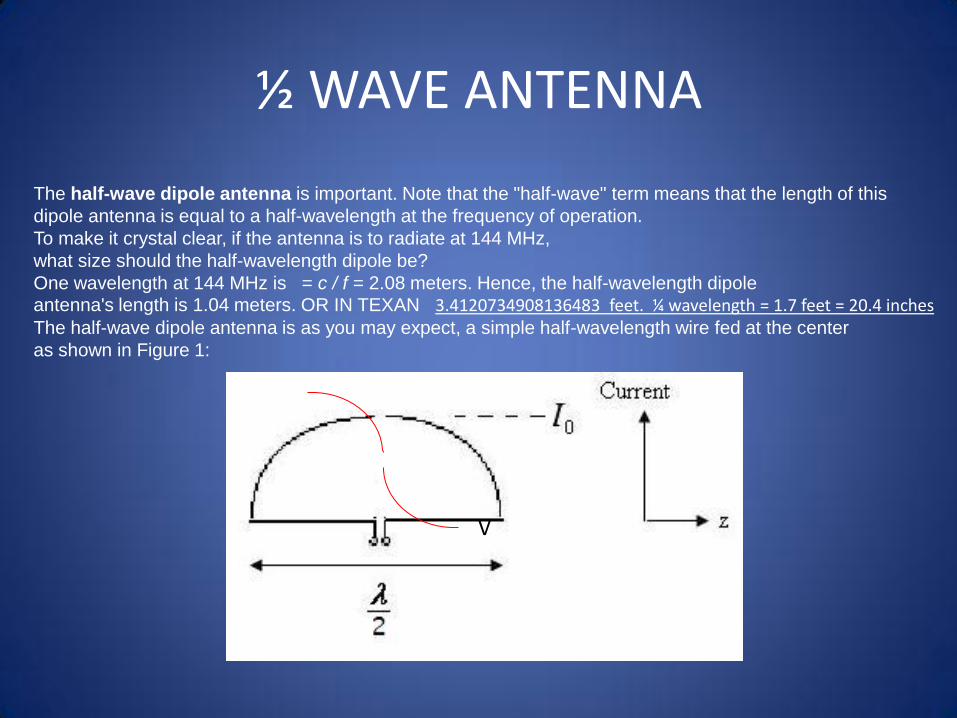
½ WAVE ANTENNA
The half-wave dipole antenna is important. Note that the "half-wave" term means that the length of this
dipole antenna is equal to a half-wavelength at the frequency of operation.
To make it crystal clear, if the antenna is to radiate at 144 MHz,
what size should the half-wavelength dipole be?
One wavelength at 144 MHz is = c / f = 2.08 meters. Hence, the half-wavelength dipole antenna's length is 1.04 meters. OR IN TEXAN 3.4120734908136483 feet. ¼ wavelength = 1.7 feet = 20.4 inches The half-wave dipole antenna is as you may expect, a simple half-wavelength wire fed at the center
as shown in Figure 1:
V
Band width considerations
A standard rule of thumb in antenna design is: an antenna can be made more broadband by increasing the volume it occupies. Hence, a dipole antenna can be made more broadband by increasing the radius A of the dipole.
the fatter the dipole gets the lower the resonant frequency becomes. In other words, if an antenna is to resonate at 100 MHz, the resonant length decreases as the dipole gets fatter.
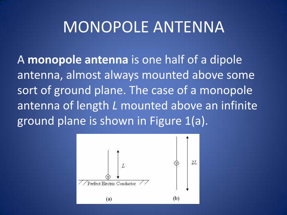
MONOPOLE ANTENNA
A monopole antenna is one half of a dipole antenna, almost always mounted above some sort of ground plane. The case of a monopole antenna of length L mounted above an infinite ground plane is shown in Figure 1(a).
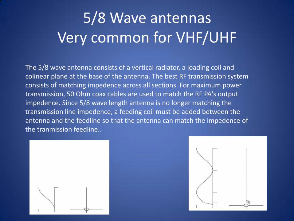
5/8 Wave antennas Very common for VHF/UHF
The 5/8 wave antenna consists of a vertical radiator, a loading coil and colinear plane at the base of the antenna. The best RF transmission system consists of matching impedence across all sections. For maximum power transmission, 50 Ohm coax cables are used to match the RF PA's output impedence. Since 5/8 wave length antenna is no longer matching the transmission line impedence, a feeding coil must be added between the antenna and the feedline so that the antenna can match the impedence of the tranmission feedline..

COLLINEAR ANTENNAS
In telecommunications, a collinear (or co-linear) antenna array is an array of dipole antennas mounted in such a manner that the corresponding elements of each antenna are parallel and collinear, that is they are located along a common line or axis. A collinear array is usually mounted vertically, in order to increase overall gain and directivity in the horizontal direction. When stacking dipole antennas in such a fashion, doubling their number will, with proper phasing, produce a 3 dB increase in gain.
BEAM ANTENNAS
A directional antenna or beam antenna is an antenna which radiates greater power in one or more directions allowing for increased performance on transmit and receive and reduced interference from unwanted sources. Directional antennas like yagi antennas provide increased performance over dipole antennas when a greater concentration of radiation in a certain direction is desired. All practical antennas are at least somewhat directional, although usually only the direction in the plane parallel to the earth is considered, and practical antennas can easily be omnidirectional in one plane. The most common types are the yagi antenna, the log-periodic antenna, and the corner reflector, which are frequently combined and commercially sold as residential TV antennas. Cellular repeaters often make use of external directional antennas to give a far greater signal than can be obtained on a standard cell phone. Satellite Television receivers usually use parabolic antennas. For long and medium wavelength frequencies, tower arrays are used in most cases as directional antennas.

Radiation Angle
In the field of antenna design the term radiation pattern most commonly refers to the directional (angular) dependence of the strength of the radio waves from the antenna

Polarization An antenna is a transducer that converts radio frequency electric current to
electromagnetic waves that are then radiated into space. The electric field plane determines the polarization or orientation of the radio wave. In general, most antennas
radiate either linear or circular polarization.
Typical Applications Vertical polarization is most commonly used when it is desired to radiate a radio signal in all
directions over a short to medium range. Horizontal polarization is used over longer distances to reduce interference by vertically polarized equipment radiating other radio noise, which is often predominantly vertically polarized.

QUESTIONS?