vi, ,,/67531/metadc63215/m...vi, _ i?atiohal advisory committee for aiueoitatjtics. ho. 929...
TRANSCRIPT

r/6s-,
. .
M.
‘.
b’-
.
.- .. .. . -.——- -—- — - - ,
.-.. .
,,
..
TECHIJICAL MEMOR&tbtiS
Vi, _
I?ATIOHAL ADVISORY COMMITTEE FOR AIUEOiTAtJTICS
.
Ho. 929
AERODYNAMICS OF ROTATIl!TQ-WIli?GAIRCRAYT WZTH
BLADE-PITCH COETHOL
By A. PflUger
‘ImftfahrtforschungVol. 16, NO. 7, July 20, 1939
Verlag von E. Oldenbourg, MUnchen und Berlin
-... . .
WashingtonFebruary 1940
1’ .-. -.
.
/’,,J.

Ill~llp#JiiiJuiil’illl:..-\—————..._____NATIONAL ADVISOR? COMMITTEE ~OR.JMBOl?A~lCS
.“ TECHHICAL UMORAHDUM MO- 929L. .. . . .-.-, ..“,- -... ... ,, . . . :.,. -.-..,,,L. .AERODYl!IAMICS OT.ItOTA~IllG-WIIUlAIRCB+ WITH “-”- “ -
.“ BL~E+ I“@E OOMT~OL *. : ...”
“By A: PfIUger.. . .. . .
> .. . . .
In the studies that have thus far appeared on the “aerodynamic of rotating-wing aircraft. rotor ey0tem8 areInvestigated of such a oharacter that rotation of theblade ‘about Its span axis, except for torsional deflection.ita excluded from consideration. In the present report,with tho zild of tho usual boniputation methods. a rotor islnv~stlgated the pitch of whose blades Is capable of beingcontrolled in such a mhnner that It varies linearly withtho fla~ping angle. To test tho effect of this linkage onthe aircraft performance, the theory is applied to an illus-trcbtivo example.
I. PRELIMINARY ~?4ARKS
1. Control Linkag6 “’
The aerod7namlcs of rotating-wing aircraft has boon C.troatod In m considerable number of published reports-Those aro all concerned with wing sybtems for which therotor blades. hinge-connected to the axis of rotation.possess two degrees of freedom; a motion of rotation of eachblade In the-piano of rotation, pormittod by the swivelinghinge In tho rotor disk (plnno containing tho hlngo and thoperpendicular to tho rotor axis). and”at flapping motion atright angles to tho rotor disk pormittod by the flappinghinge, With this Qrrangemwntt no deflection of the bladeoccurs about Its span axis. Tho blade pitch. that 1ss ‘thoanglo betwoon tho zero lift lino of tho hlado sect~on andtho piano of rotatton (fdg. 3). Is thus doterminod by the. .design and remains constant during the rotation of--thewing system= :.
*nAorodynamik des Drohfltlglors mlt BlattwinkolrUckstouorung- “ ‘Luftfnhrtforschung9 vol. 16. no. 7, Jul~ 20. 1939. pp. 355-361.
—- - .--— .—

—— —-- ——. ..— — .. . —.
.
ll.A.C .A. !l?echntcbl Harnorandum No. 929 :
In recent times, a differpnt kinematical system hasproven Iteelf practically applicable. With this system,a rotation of the wing about its span axis, In additionto flapping and” ro~~tlng, is possible, This yariat~on ofthe blade pitch is, however, positively coupled with theflapping angle in euch a manner that” the. upward motion ofthe blade reduces the blade pitch- The process can bestbe understood by considering tho do~ign of the rotor sys-tem In detail. Such coupling has been practically a plied
7to tho Brdguot hellcoptor (German Patent Ho. 567,584 62b(1933) ) and the Hafner gyroplane (roferenoe 1). Sinco thelatter Is doscrlbed in dotall in the literature, the ar-rangement of its rotor~ system has been used as tho baBisfor our computation.
The ossontjal characteristic of the design Is theso-called ‘spldorti shown in tho sketch of figuro 1, Itconsists of the spider axis and the spider arms which areconnected with the rotor blades through hinges G andLovor arms H. The rotor blades aro attached to the ringR through a Cardan bingo K, making possible the changoin blade angle with flapping angle. In the Hafner gyro-plane, the flapping hinge is through suitable means placedin the axis of rotation. In figure 1, the more generalcage of a distance e between the hinge K and the ax~sis assumed. Tho spider axis may move up and down In ringR and be inclined in any direction. The possibilitiesthus providod for tho change In the blado pitch aro ofgroat importance for the .contrbllablllty of the aircraftbut will not be considered further here- We are inter-ostod only in the relation lotween tho flapping and bladeanglo for steady flight conditions with constant. settingof the spider axis with rospoct to the ring R. This re-lation may bo derived with tho aid of figuro 1. Lot theflapping angle be donotod by e, the blade pitch by ~(see figs. 2 and 3); for P = O, let d = do. E’or an up-ward motion of the blade point A at which the lever arnH is attached to the blade spar, movos up by tho amount~(a-o)s Since the position of the.hinge G remains un-chan~od, the blade pitch is decreased by tho amount
relations
~or briofnoss, we sot
.-— —-—
3iA. C.A* Toohnloal Metiorandum .lTe..,929 3
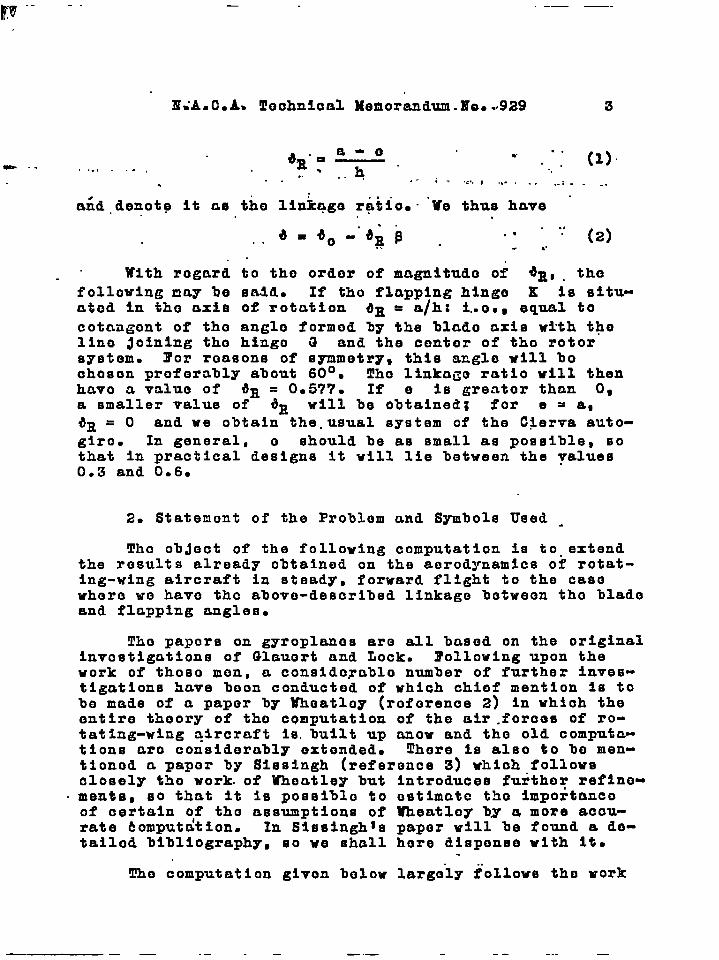
~-od~”:y. ‘ “ ..; : (1)- .. ....-. ., ... . ... :. ..... ,,..,,, -:-- ..
..” ‘: (2)
. . .
With regard to tho ordor of magnitudo of 6E0 . the
following may be sa.ld. If tho flapping hinge K is situ-ated In tho axis of rotation dE = a/h: i..o., equal tocotnagont of tho anglo formod by the blado axis wtth thelino Joining tho bingo G and the contor of tho rotorsystemg I’or reasons of symmetry, this angle will lIochoson proferahly about 60°~ Tho linka~o ratio will thenhavo a value of *R = 0.577. If e is greater than 0,a smaller value of *R will be obtained; for e = a,ilR = O and we obtain the.usual system of the C~erva auto-glro. In general, o should be as small as possible, sothat in practical designs it will lie between the values0.3 and 0.6.
2. Statenont of the Problom and Symbols Used -
!FI1oobject of the following computation is to. extendthe results already obtained on the aerodynamics of rotat-ing-wing aircraft in steady, forward flight to the casowhero wo havo tho above-described linkage botweon tho bladoand flapping angles.
Tho papers on gyroplanos are all based on the originalInvestigations of Glauort and Lock. Following upon thework of thoso men, Q consldorablo number of further inves-tigations have boon conducted of which chief mention Is tobe made of a paper by Whoatloy (roforence 2) In which theentire theory of tho computation of the air .forcos of ro-tating-wing qlrcraft 1s.built up anew and tho old computa-tions aro considercbbly oxtonded. There Is also to bo men-tionod a paper by Sissingh (reference 3) which followsclosely tho work. of Wheatley but Introduces further refino-mentsD so that it is possiblo to ostimato tho Importanceof certain olf tho assumptions of Wheatloy by Q more accu-rate &omputation. In Sissingh~s paper will be found a de-tailed bibliography, so we shall here dispense with It.
Tho computation glvon below largely follows the+ work
— — — .— — — .— -- - .- —

...
—1
. ...
4 IT. A. C...A. gochnieal Memorandum No.. 929
of Wheatloyb Vo may thoroforo disponso with a detailedoxplnnatlon of tho assumpfi~ris and formulas which hold forall rotating-wing aircraft indopondent of any particularklnomatics of tho wing syqton. !J!hoinvostlgatlon Is ro-strictod to the slnplost caso of untwlstod rectangularblades: I.e., tho blado pitch do, and tho blado chord aroconstant. Tho blado twist due to torsional nonents abouttho blade-span axis is by suitable constructive moans(snallost posslblo distanco between blade ccnt~r of gravity,shear contor of blade cross soction~ and center of prossuroof blado section) hold low enough so thnt It nay bo no-glocted.
The following notation is usods
R, rotor radius (distanco Qf blado tip from rotationOXIS):..
z~ ~unbor of rotor blades:.
t, blado chord:. .
ata=— s31icity;
nR’
v, forward velocity; “
w, angular velocity of tho rotor blades;
w, Induced velocity;
a, angle of attack of tho rotor-disk.
Then
V cos a is tho componont of tho forward velocity inthe rotor disk;.,
Vsina-v, component of tho forward voloclty normalto the rotor ”disk (fig. 2).
.
Fron those, we further dofino tho nondimensional coeffi-cients:
V cos aP=—. WE ‘
A=V sin a - w
UJR
—-. ——— -, .,..- . ...,,. . . . . . . . . . , , -, -, , - .

—.
.--1:...
MiA. C..A. “l?ochnieal Monoranduh J?o~ 929 5,
A, “rotor lift: .“c.. . ,. .
w, ““ “’‘“” ‘-‘rotor drag (no-t of “th’oelitlro aircraft); .,.. .... ..
s, rotor thrust (oonponont of. tho resultant airforco in the dlrootion of tho axis);
For tho purposos of our investlgction, wo may withsufficient accuracy set S ,oqual to tho resultant air “forco, so that A = S cos ctt “
~d , applied nonont of tho rotor blmdes about thoaxis of rotation (for tho autogiro Md = O):
slcs=l thrust coefficient:
5P w“ R’11’
wc lift-drag ratio;
= x’
Tho abovo-doflnod aagnitudos refer to tho rot~tlng-wing systen as a wholo. E’or tho flow and lift relationsat each blade olenent, the following symbols aro used.(See fig. 3.)
r, dlstnnco of a blado elenont from the axis of rota-tion;
rx=—;
R
n, blrulo nass per unit length along blade span;
R
J = r Qr~dr, nass nonent of inertia of a blade
JJabout the polLt r = O;
f
E
‘g = ngrdr, ponont of tho blado weight about
“othe point r = 0:
CLr~ angle between zero lift line and resultant flowat blade elo~ent at position r;
Ca* blade section lift coeffioiont:
cats constant ne~ value of slopo of curve Ca =“ f(ar) ;
.
1.- -. ————— --- ._
.—. .- -- .---- —
.
I
6 Ii.A.&A~ Technical Memorandum no. 929
~, constant noan Tnluo of drag coefficient Cw ofbl”ade seotlon; .
upw R, velocity at blado olenent parallel to rotoraxis ;
ut(J.)R, velocity at blado elonent In the rotor disk;
v=% angle botweon direction of resultant flow and‘% rotor disk;
v, azinuth angle of blades noasurcd in piano ofrotor (fig. 2);
tR4c 1Y=J’.a, blade nass constant;
J
145, nomont of air forcos of a blade about tho flap-ping }.in~o; .
B, factor to tako account of the tip losses.
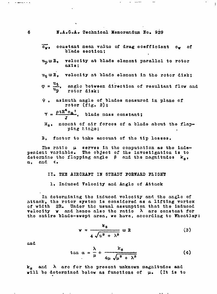
!EMe ratio k serves liI tho conputatlon as tho inde-pendent varla3le- Tho ob~ect of the invostlgation is todotornlao tho flapping angle ~ mad the nagnitudos ks,a, cad co
II* THE AIRCIW?T IN STEADY FORWAHD ~LIGHll!
1. Induced Velocity and Angle of Attack
In dotornining the induced voloclt~ and tho anglo ofattack, the rotor syston is considoro& as a lifting vortexof width 2R. Under tho usual assumption that the inducedvelocity w and hence also the ratio A aro constant fortho entire hlado-ewept area, we huve, according to Whontley:
ksw= WR
4-
cm d
(3)
(4)
ks and A aro for tho present unknown nagaltudos and
will ho dotorninod below as functions of p. (It iS to.
. . ---

EiA.C.A. Teohnical Monorandun.HQ. 929 7
bo notod that between the thrust coefficient k~ and themagnitude CT enployod by Whoe.tley tharo is the relationk~ = 2Cg )
n
2. R’low Volocitlos at Blade Elenent
l’or the velocity at tho blado olenont in tho piano oftho rotor, wo obtain
ut wE= Wr.+
Ut = x+ ~
and for tho velocity parallel
d$~wR= AWE-r_dt
xd~up . ~. -— - v
wdt:
~ 18 tko derivativewhorodt
stn~ (5)
to tho rotor axis
-~wRpcos*
$ COE* (6)
of tho flapplng anglo B
with rospoct to tine. The an@o ~ (acuto cnglo betweenthe bl~de span axis nnd tho rotor disk) is expressed intorr~s of tho azinuth anglo ~ by a Z’ourior sorios in whichterns only up to the second harnonic aro retained:
There is then obtained fron (6), with W = UJ t
The radial velocity in the direction of the %lade spanaxis need not be taken Into account. Its effect on the
.— —. .. —

8 IT. A.C*A. Tochnlcal Memorandum Ho. 929
magnitudes to be invebtlgated will as usual be ncglocted-
3. Flapping Anglo
The flapping motion .~ is obtained by determiningthe Fourier coefficient ao, al, ‘il. a~ baa In most ofthe Investigations on the aerodynamics of helicopters andautogiros , the second harmonics aa and baa in contr~stto the procedure of Wheatley, are dropped, being consid-ered negligible. This is Justified by experience as longas we are mainly concerned with the a.orodyn.amic behaviorof tko rotating-wln~ system in its total offoct: i.e., inthe mcgnitudos S, A, W, UI, V. For the designer, it isimportant, howover, in ordor to ostimcte tho strength ofthe rotor blades, to know as accurately as possible theair forcos at onch blado olcmont which forcos firo con-siderably nffoctod by tho second hnrmonic of tho flappingmotion. Tho coofficionts aa nnd ba aro thoroforo intho following retained.
The dlfforontial equation of tho flr.pping motion Isobtainod from the momont oquilibri-am equation about thefl~pping hinge. In this condition thoro ontcir tho airforcos, the inertia forcos of tho flapptag blr.do, tho cen-trifugal forcos, and tho weight. With tho notation givenabove, thoro is obttiinod tho known relation
(9)
It is hero assumadping hinge cmd theso that its effect
The monent ofunder the assumption thr.t the resuitant velocity at theblmie element is with .sufficieat acc-.~racy given 3Y .vtulR, is
that tho distnuco e botwoon tho flap-axis of rotntioa is zero or small enoughmay be neglected.
the nir forces nbout the flapping hi~ge,
Ms = /’ ~ptutawaRacardr
●O E
~.ls= ~pt~aRqr
Ut a caxdx (lo)
.-—— . .— .. . . - _ . _ . . —. --- .-

!!.
.R. A.C.A. !l!echnical Memorandum Ho. 929 9
LTo take account of the thrust 10SSCS at the blade tip, woIntogrcbto, followlng Wheat loy, not up to B but onlyup to BR, where
-. . .
I.1,.(
. How
tB=l.—
2R
c~ = cat ar
and from figure 3
ar =13+q)
With the aid of (2), there is then obtained
ar = do 3- a# + ~t (11)
This holds, however, only for the advancing blade section.For the retreatin~ blade (n<~<2Tr and Oe r<-Wrsin w), a is as usual replaced by -ar and it Isassumed that t~e slope Ca’ of tho lift curve has approxi-mately tho scmo value aa for tho advancing blade. Wo sot
MsI II
= MB + Ms
Iwhoro ‘s is tho air-forco moment that Is obtainod by
substituting tMSII aglo ar
valid for tho forward movingblndo, and is tho correction term that takes thorotroatinG motion into account. From (10), thoro is ob-tainod
-. ---- ----- —- .-—

.
14a-c)
(16 a–~
M=-~etdf14ca’
[(2 2 M.~ a0+3a’cos 2y+3b*sin2~ ——yJOJz )1(16)
et fP c.’with y.—BY comparingthe coiffi;ientmof the trigo.,nometricfunctionsof equations(13) and(16), the followingrelationsare obtained.
2 – 2M0 ~uo+—
7 .YJW2 ‘- 0,
Al= wB,= O, I
6
I
. . . (17 a–e)~ aa= A*,
:b,=B,
Equations(17) in connectionwith (15)●re now to be solvedfor the Fouriercoefficientsof the flappingmotion.It in sufficient here to compute ao,a~, bl up to terms of the order ofmagnitude lJ4 and aa, ba up to termsof the order of Vz. Under this asmmp-
1 I
.-——fish * a,b) “
,.
nfp = -Qtdl{’c:$[(o.-o#B).’’+,lsdzsdzWith the ●id of (7), there is obtainedfrom (9)
IJforn<p<2n
U8 18 now developedinto a Fourier#cr-ies of which again only termsup to thesecondhanmonicare retained:
JIs=~ef w~NcO’(Ao+A1cos~ +Blsin~
+A,cos2v+B,sin2@ . .. .(13)
*or each of the harmonics,if the emall effectof the retreatingmotion i. taken into accountonly in the coefficientsAo, A=, and BL, thefollowingexpressionsare valid:
2X
Ao=&
J
M:—.—d~
1~e ~~2 p ~a,
0Zz
J
@I
+: - dv,
~e td Ra,ca’
.
Al, B,= ;
1
‘mM~(cos~,sin~) dv
--i-~e tUJzR4ca’
02X “
J
lf~(cos~,siny)+; ~ —dy,
~e td R Ca’
n
I
2zM~(cos2y, sin2~)dvA,, B, = ;
1~e t& W cc’
Substikting (5), (8),and (7) in (~)and then in (14), there is obtained,after carrying out the intagratione“AO=;ABS+&A~,+;PSBsb,
(+O.+ B4+P8BS—;P
‘)
.(—%+ B4%+P2B’UO—+P%
)—~pBabl+~paBsa, ,
4A1=—&sB8ao—.=p ‘ao+~Babl
+~pzBZbl—~pBSa,
( )+@R_$ B~al+&aBsal+&Babs .
1 B,&lB1=;ApB,—&a-~
+~pzBZal—~pB3b,
(
8+00 ;PB’+F--P4
)
(
s2 B8UU+WXP 4 a.—~. ~P
* B8a2,_:B,b1_;paB2b,+~~
)
An=~p B3a1+~B&b,’— ~pBB’@o
(+08: PsBsao—Tp 4 B8b1
)’+Btat+#Baa2 ,
tlon aa and b= may be determined -from equatione (17 d,e) if, in the ex-pression for Aa and Ba, the follow-ing approximation values are substi-tuted for the coefficients ao, al , bl
(‘- 8+ YILB’ 3 )~AB3+t90B4,
2p“- B2(l+t?8a) ( )1
A+$Bt%—~BO,aO, (18a–c)
IThese relations are obtained from (17),if in (17a) for the computation of a.only terms without p are retained andin (17 b,c) for computing al, bl onlyterms with vi. With the aid of (18)0there is then obtained from (17 d,e)
b,=B, #
72+9 Y19EB1
0,1YB*—40a—60$OB—~Oo0,yB5x
( )W+ ;—;B48R2 ,(19a,b)
7YP2B“= 18(8+yo,B4)
( )(X ;A+60B —L ~—;B8,
B4 y )Knowing aa and ba, the remaining co-efficients of the flapping motion may bedetermined from (17 a-c) up to the orderof magnitude of V4. Oarrying out thecomputation, there is obtained
I

... ,
N. A.O.A. Technical Memorandum” .No. 929 11
with(.)”
fbl= B*+; Ps (l+ I?,s)+, ZP*f&
(
,_~.9?,=+ IY+wp
,, )*P**
P ..-. ,. _:, ,.‘a~= 1
~L#(l +a,s)+lFp**=-., .z,
[ (
,=.
x LW+; IP’W ;P+;A’B -
)(+##8 -#p ;&a 1,—TjOBao+&%Fao
++.B3q) 1
-;lFb, (l+2t?#) , . .
4#’61= ——
JY+~pa Bs
(X +Bs%+*xpsao+~~aa—~ s10 Bsb,
)— % A
4. Thrust Coefficient
For the total thrust of all of thes bladee,there ia obtainedfor on.revolution the mean *alti
For the thrustcoefficient,there in obtained
.31where ‘U=’z
Sub#titut~ the w1O of ●ttack ar &nd ●zb-dividlng the range of Integrationfor advancingand retre~tingmotion, there ie obtained.
2ar B
ks=~{ff,(oo-o,,) w,+u,u,ld.dv
9.= —pe.ln+
-2J O;[($o-o*P)ut’+utuzldzdv1 (m)With ;ho ●\d of (5), (8),and (7)0 thereIs obtainedfrod (20) after e~aluatingthe integralsuof ~llltude $’ ‘o ‘ems of the Order
‘“=”’”’{i’(B’+i~’)+~”i(B’+:~’~-+~’)
[(++ P’%++ P*%-% ;an BS+:P’B
I
(21)
-a’a)-+’b’(B’++ 4++”2Ba’1}6. Drag-LiftCoefficient
TO detmrmino the drw,ana power ofthe rotora knowledgeof the drag-liftratio c .18requirad,the latterbeingcomputedfrom the ●nergy losoeaof therotetlng-wing9y*t3m. Those 10s800●rise from the inducedvelocity●nilfromthe dragm at each blade ●lsment in ro-tating. The first-namedportion of thelesseeis eb$aiaod.from coneiderationa.on tb rotor ●y8tem in its total effect,the corre8pondlng fomulas not being●ffected by the linkagebetweenthepiteh and flappingangles. The linkageratio ~R doee not ●nter into tho
second portionof the lossesbecauae●
mean value of ~ independentof theangle of ●ttack Ie used in detenetni~
the d- of a blade ●lement. Wheatley~8value of the lfft-dmg ratio can there-fore”bo taken over w~thaut●odtfioation,him ●xoreasionbeioc
=- ~“a—( )l+3#?+.f/4 +kg
4pks(22)
4#fm” ‘-“6i”-IWincoof Ucunte”about the
YertioalHinge
AU of theaagnltude8 thue fg d@-terdned containthe nondimensionalra-tio A whose dependenceon )1‘Is #tillto be determined. A relationbetween A●nd p. ie obtaimd fraa the conditionof ~nt equilibri= about the verticalhinge. This conditionis
2.BR~d.k&f-$+Qtw,(..Rc.vrdrdw
-iii%tut”dlt’’~wrdrd~=()
or00
z- Blw~
1 +f$uhqmdzdy~@ w%RGcr “ “
~= ,
Tho first of the double integralerepresent the contributionof the liftto the moment, the second,the contribu-tion of the dreg. The latterintegral18 to be integratedfrom O to 1, not onlyto B becauaethe drag ie not decreasedby the thrustdrop at the blade tipm.Takingaccountof the retreating ❑otionof the bladea, there1. obtainedafter●ubetitutingthe expressionsfor Cati ~
z
h—/4sln14
—2 [(~o—~.~)u.w+u,’lzdzdvt
(23)
00‘2= 1 2m—pslntp
-WV utazdzd~+2~f futazdxd~ 1?erform& the integrati&’and rearran&r-lng the t&e. ther~ is finallyobtalne~
.— —

la E.A.C. A. Technical Memorandum Ho! 929
The practical computation of the ratio A afl a func-tion of M is somewhat difficult since (24) contains thecoefficients of the flapping motion, which coefficients,accordin~ to (19) , again depend on A and ~ If A isknown, however, no difficulty Is encountered in determin-ing B, CL, ks, and G.
III. ILLUSTRATIVE EXAMPLE
The formulas set up in the preceding section will nowbe applied to a numerical example. The ob~ect of the com-putation is not so much to clarify the process of practicalcomputations as to obtain a numerical estimate of the slg-nificanco of the pitch and flapping angle linkage on theaircraft performance.
As an example, there will be chosen an autoglro oftho usual present-day design. Tho initial values used asa basis for the computation and which approximately corre-spond in their order of magnitudo to tho design factorsused for the C 30 typo autogiro aro the following:
G= 900 kg Md =0
R= 6.00 m Caf = 5.6
z = 3 Cw = 0.014
t = 0.28 m do = 6°
J= 25.9 mkg S2 ‘R = 0.45
B= 0.98
With these values, there Is obtained from (19) Inconnection with (24) the variation of the Fourier coeffi-cients of the flapping motion with p shown In figure 4.In figure 5, ks Is plotted from (21) and in figure 6,the lift-drag ratio ~ from (22). ~or A = G,
As—=
cos a
the rotational speed n = $UJ is obtained from
—.-—— -.. .1

. .. —— —___
... . ..- . . . . . .
M.A. C.A. Technical Memorandum
Jis =“s’
.!,. ,. ‘1 “- -“---aB? G-”~pu
Ho. .929 13 .
.._ .- ------
The result is plotted in figure 7 for G = 900 kg. Thedopondenco of tho forward speed on +L+ which is obtainodfrom the relation
I.bwn .. ..T=—
. cos a
is shown on figure 8. Tho maximum velocity of tho aircraftwill lie near tho valuo p = 0.4 (V = 208 km/h). For thisfli~ht condition, flgurc 9 shows tho corresponding flappingmotion.
Tho coofficlont a., donotod as tho coning angle, hastho valuo 4.73°. To a flapping anGlo of this magnltudo,thorc corresponds tho blado pitch anglo
dp = Llo = T90 - *R Eio
= 6 - 0.45X4.73
= 3.87°
Tho rotor thus oporatos on tho avorago with a pitch of theusual ordor of magnltudo of about 4°.
!l!hoimportant result brought out in figures 5 to 9is that tho autogiro Invostigatod hnving the blade pitchcontrol doscrlbod doos not show any particular, unoxpoctcdproportion but bohavos ontiroly liko m normal autogiro oftho Ciorva typo. (Conpare th~ conputntions of Whoatloy,H.A.C.A. Reports Hos. 487 nnd 591.) Particularly note-worthy is tho fact that tho amplitudo of tho flnpplng mo-tion, i.o.s chiefly tho coefficient al, iS Of tho utau~l
magnltudo t so that the type of llnkagc dcscribod doos notgQS night havo boon oxpoctedm load to a docroaso In thoflapplng not~on.
All this loads to tho final conclusion that tho kino-matlcs of the blade-pitch control of the autoglro, while
— .. —-—. — -..

14 IT.A. C.A.. Technical Memorandum Ho. 929
offering no disadvantages, does not offer any particularadvantages as far as behavior In stea”dy forward flight isconcerned”. It Is true that in flight under gust condi-tions the linkage gives the rotor less sensitivity to thegust. The use of the linkage will hardly prove worth-whllo, however, unless othor advantages are gained throughits application. The advantages of the spider construc-tion doscrihod in section I aro to ho found chiefly in thecontrol possibllitios of tho rotating-wing system, becauseof the fact that tho spider axis may bo displaced up anddown or tilted to tho sldo In tho ri~g R. Tho offoct oftho llnkr.go is to be considorod a by-product conditionedby tho design which, howuvor, doos not Impair tho aorody-nanic behavior of tho aircraft. It should bo pointod out,howovor, that ccution nust bo omployod In gonornllzingtho results ottainod from tho coraputation oxcmple to link-ago rmtlos that consldornbly cxcood tho valuo of ‘R = 0.45invest.lg?.tcd.
IV. SUMMARY
.
Tho method developed by Wheatley for tha computationof the air forces of rotating-wing aircraft is extendedin that Instead of a constant-blade-pitch angle a lineardependence Is assumed between that angle and the flappingangle. The application of the formulas obtained to anautogiro with a linkage ratio of the usual magnitude showsthat for steady, forward flight no particular effects ariscion tho aerodynamic behavior of tho aircraft.
Translation by S. Relss,Eational Advisory Comnlttoofor Aeronautics.
..— -— —. -- I

.—.
[
. . . . .. ----- —
H.A. C.A. Technical Komorandum go. 929 15
REI’J!UUITCES-s ,, - .,..-,..-
.,. -,. . ,- --------- . . . . . -. -,,-.--
1. !Cho Hufnor Gyroplane, Tho Aoroplmno, Yeb. 17, 1937,pp. 197-98.
The Hafnor A.R.111 Gyroplano (British), A.C. Ho. 205,liTsA,C.Ao, 1937-
Tho Hafner Llyroplane A.R.III, Englnooring, Hay 28, 1937,ppo 600-020
2. Whoatloy, John B.: An Aerodynamic Analysis of the Auto-giro Rotor with a Comparison between Calculated andExperimental Results. T.Il. HO. 487, H.A.C.A., 19~34.
3. Sissingh, G.: Contribution to the Aerodynamics of Rotat-Ing-lrlng Aircraft. T.K. ~0. 921, N.A.C.A., 1939.
—--- —. —. -. —

.-
IIALC.A. Technical memorandum Ho. 929 , Figs. 1,2,3
A AxiEIof rotation
. .- .. . . . ‘W
//
Figure 1.. Autogiro rotor with llnkga between theblade pitch angle and the flapping angle.
Figure 2.- Velocities and forces of the rotor system.
Figure 3.- Velocities at the blade element.
——- -— ..— -—- —- -. --

——— . . .
m
11.A.C.A. Tecmlcal Wnorandum No. 929 Vigs. 4,5,6,7,8,9
.1 .2 .3 .4 .5IJ
~igure 4.- Fourier coefficients ofthe flapping motion as
a function of the w .
#.008+h“g.oo7u
E!“.006
#
.1 .2 .3 .4 .5M
9ookg.
.1 .2 .3 .4 .5u
Ji’lgure8.- Forward velocity as afunction of IL for G=Yooiqg #
Figure 5.- Thrmt coefficienta function of K ,
w.
w IYgure 9.- Flapping angle aO a func-Flgure 6.- Rotor drag-lift coef-
ficient as a functiontlon of the azimuth angle
for G=900kgand M=O.4 .Ofb.
I —- .. .-.. . . .— .. .-— .-

..
,,-,
%., ,+
“,-,*
.’
,,,
,, ,,
.,
,.
!.,
,.. —.