v.i. karas et al- kinetic simulation of fields excitation and particle acceleration by laser beat...
TRANSCRIPT

8/3/2019 V.I. Karas et al- Kinetic Simulation of Fields Excitation and Particle Acceleration by Laser Beat Wave in Non-Homoge…
http://slidepdf.com/reader/full/vi-karas-et-al-kinetic-simulation-of-fields-excitation-and-particle-acceleration 1/3
KINETIC SIMULATION OF FIELDSEXCITATION ANDPARTICLE
ACCELERATION BY LASER BEATWAVE IN NON-HOMOGENEOUS
PLASMAS
V.I. Karas’, Ya.B. Fainberg,
Kharkov Institute of Physics and Technology, National Scientific Center, Kharkov, 310108 Ukraina,
V.D. Levchenko and Yu.S. Sigov,
M.V. Keldysh Institute of Applied Mathematics, Moscow, 125047 Russia
Abstract
Resonance excitation of longitudinal plasma electrostatic wave
by double-frequency laser radiation is investigated numerically
to study in detail conditions of particle beat wave accelera-
tion. The computer simulation is based on the highly special-
ized code SUR, using splitting technique. Both the space uni-
form and slightly non-uniform cases are investigated. Maintain-
ing of phase synchronism between accelerated particles and ex-
ited longitudinalwave is provided by a choice of density plasmaprofile.
I. INTRODUCTION
The method of charged particle acceleration by charge den-
sity waves in plasmas and in non-compensated charged parti-
cles, which Ya.B. Fainberg proposed in 1956 [1], seems to be
one of the promising methods of collective acceleration [2],
[3]. The primary challenge in all plasma acceleration schemes
is to produce a substantial plasma density perturbation with a
phase velocity to be close to velocity of light c . At present the
most promising concepts are plasma beat–wave acceleration and
plasma wake field acceleration.In the plasma beat–wave acceleration scheme [4], two coprop-
agating laser beams with slightly different frequencies are in-
jected into a plasma. C. Toshi at al (1993) obtained the electric
field strengths of the charge–density wave of 0 7 1 0
7
V
c m
, and de-
tected the accelerated electrons with an energy of 9 1 M e V
(in-
jection energy was 2 M e V ). The resonant plasma density was
8 6 1 0
1 5
c m
3 , but already in January 1994, the 1 c m length,
the electrons acquired2 8 M e V
.
Resonance excitation of longitudinal plasma electrostatic
waves by electromagnetic waves is investigated numerically
with helpof the SUR code. The SUR codeis based on solving the
finite–difference analogs of the Maxwell and Vlasov–Fokker–
Planck equations throughthe successive use of the splittingtech-
nique over physical processes and variables of phase space.
In order to economize our machine time, we do not yet pose
the problem to be solved with its real parameters [5].
II. COMPUTATIONAL MODEL
Consider a linearly polarized electromagnetic wave propagat-
ingin the x direction with the electric vector ~
E directed along the
The workis partly supportedby the InternationalScientific Foundation,grantU27000 and Russian Foundation for Fundamental Research, project no. 94-02-06688.
y –axis and the magnetic field vector ~
B oriented along the z –axis
( p –polarization). The action of such a wave onto plasma parti-
cles can give rise only to the V
x
and V
y
velocity components. In
the case where the distributionfunction does not depend initially
on y and z , three phase space coordinates x V
x
V
y
are sufficient
to describe subsequent plasma behavior; the relevant distribution
function is f ( ~ r ; ~ p ) = f ( x V
x
V
y
) ( V
z
) .
The plasma electron dynamics may by described the Vlasov
equation
@ f
e
@ t
+ V
x
@ f
e
@ x
e ( E
x
+
V
y
c
B
z
)
@ f
e
@ p
x
e ( E
y
V
z
c
B
z
)
@ f
e
@ p
y
= 0
This equation is solved by a variant of the method of splitting
over phase–space coordinates[6].
Effects due to charged–particle collisions in the plasma can-
not significantly affect the time of electromagnetic wave prop-
agation through the simulated system. Because of this, we do
not take the Fokker–Plank collision term in the equation into ac-
count.
The similar equation might be written for the plasma ions;
however, in these computations the ions, being heavy compared
to electrons, were assumed to be motionless.
The longitudinalelectric field E
x
is determined from thePois-
son equation, which, in one–dimensional case, can be written as
E
x
= E
x L
+ 4 e
x
Z
x
L
( n
i
( ) n
e
( ) ) d
where n
i
( x ) is the ion background; n
e
( x t ) =
R
f d ~ p is the
electron density; x
L
and E
x L
represent the coordinate and field
value on the system left boundary, respectively.The transverse electromagnetic field must be satisfy the
Maxwell equations:
1
c
@ B
z
@ t
=
@ E
y
@ x
1
c
@ E
y
@ t
=
@ B
z
@ x
4
c
j
y
where j
y
= e
R
f
e
V
y
d ~ p is the current density. The latter two
equationscan be written in a form more convenient fornumerical
computations:
8/3/2019 V.I. Karas et al- Kinetic Simulation of Fields Excitation and Particle Acceleration by Laser Beat Wave in Non-Homoge…
http://slidepdf.com/reader/full/vi-karas-et-al-kinetic-simulation-of-fields-excitation-and-particle-acceleration 2/3
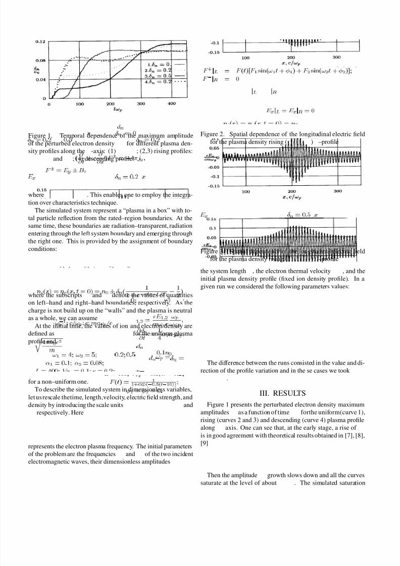
Figure 1. Temporal dependence of the maximum amplitude
of the perturbed electron density d
n
for different plasma den-
sity profiles along thex
-axis: (1)
n
= 0
; (2,3) rising profiles:
n
= 0 2 and 0 5 ; (4) descending profile:
n
= 0 2
(
@
@ t
c
@
@ x
) F
= 4 j
y
whereF
= E
y
B
z
. This enables one to employ the integra-
tion over characteristics technique.
The simulated system represent a “plasma in a box” with to-
tal particle reflection from the rated–region boundaries. At the
same time, these boundaries are radiation–transparent, radiation
entering through the left system boundary and emerging through
the right one. This is provided by the assignment of boundary
conditions:
F
+
L
= F ( t ) [ F
1
s i n ( !
1
t +
1
) + F
2
s i n ( !
2
t +
2
)
F
R
= 0
where the subscriptsL
andR
denote the values of quantitieson left–hand and right–hand boundaries, respectively. As the
charge is not build up on the “walls” and the plasma is neutral
as a whole, we can assumeE
x L
= E
x R
= 0
.
At the initial time, the values of ion and electron density are
defined asn
i
( x ) = n
e
( x t = 0 ) = n
0
for the uniform plasma
profile and
n
i
( x ) = n
e
( x t = 0 ) = n
0
n
(
1
1 + e
( x L = 2 )
1
2
)
for a non–uniform one.
To describe the simulated system in dimensionless variables,
let us rescale thetime, length,velocity, electric field strength, anddensity by introducing the scale units !
1
p
c = !
p
c m c !
p
= e and
n
0
respectively. Here
!
p
=
r
4 n
0
e
2
m
represents the electron plasma frequency. The initial parameters
of the problem are the frequencies !
1
and !
2
of the two incident
electromagnetic waves, their dimensionless amplitudes
1 2
=
e E
1 2
m !
p
c
!
p
!
1 2
Figure 2. Spatial dependence of the longitudinal electric field
E
x
for the plasma density rising (
n
= 0 2 ) x –profile
Figure 3. Spatial dependence of the longitudinal electric field
E
x
for the plasma density rising (
n
= 0 5
)x
–profile
the system lengthL
, the electron thermal velocityV
T
e
, and the
initial plasma density profile (fixed ion density profile). In a
given run we considered the following parameters values:
!
1
= 4 !
2
= 5
1
= 0 1
2
= 0 0 8
L = 4 0 0 ; V
T
e
= 0 1 = 0 2
F ( t ) =
1
1 + e x p ( 0 5 ( t 1 0 ) )
1
=
2
= 0
The difference between the runs consisted in the value and di-
rection of the profile variation and in the se cases we took
n
=
0 0 2 0 5 .
III. RESULTSFigure 1 presents the perturbated electron density maximum
amplitudes d
n
as a function of time t !
p
forthe uniform(curve 1),
rising (curves 2 and 3) and descending (curve 4) plasma profile
along x axis. One can see that, at the early stage, a rise of d
n
is in good agreement with theoretical results obtained in [7], [8],
[9]
@ d
n
@ t
=
1
4
1
2
!
p
Then the amplitude d
n
growth slows down and all the curves
saturate at the level of about 0 1 n
0
. The simulated saturation

8/3/2019 V.I. Karas et al- Kinetic Simulation of Fields Excitation and Particle Acceleration by Laser Beat Wave in Non-Homoge…
http://slidepdf.com/reader/full/vi-karas-et-al-kinetic-simulation-of-fields-excitation-and-particle-acceleration 3/3
Figure 4. Spatial dependence of the longitudinal electric field
E
x
for the plasma density descending (
n
= 0 2 ) x –profile
level is considerably lower then the theoretically estimated one
due to the relativistic shift of the Langmuir frequency obtained
for cold plasma in [7], [8], [9]:
d
s a t
n
=
3
r
1 6
3
1
2
0 3 4
For nonuniform density profiles, the saturation level is higher
than for the uniform one (curve 1). This is caused by the fact,
for the case of uniform profile, the plasma density was chosen to
ensure the exact equality of the Langmuir frequency to the beat
frequency !
s
= !
1
!
2
. During the transition to a steady state,
the location of the perturbed electron density maximum is de-
termined by the distance from the left boundary to some point,
where the plasma density has such a value that the difference be-
tween theelectron Langmuir frequency and thebeat frequency is
equal to a quantity !
o p t
(optimal frequency shift) proportional
to (
1
2
)
2 = 3
!
s
.
Figures 2-4 shows the steady-state spatial distributions of the
longitudinalelectric field E
z
for the plasma density profilerising
(Fig.2 and 3) and descending (Fig.4) along the x –axis. It is seen
that the longitudinal electric field reaches its maximum at points
where the local plasma frequency exceeds the beet frequency by
a value of !
o p t
determined in its turn bu the amplitudes and fre-
quencies of electromagnetic waves. The plasma density 1 0 %
variation within the rated region results in an acceptable spatial
distribution of E
x
. This allows one to hope (see Fig.4) that the
descending plasma profile may be of practical use in this beat-
wave acceleration method: an appropriate density gradient may
help to prolong the accelerated particle synchronism with a lon-
gitudinal beat wave [10].
References
[1] Ya. B. Fainberg. The use of plasma waveguides as accel-
erating structures in linear accelerators. In Proc. Symp.
CERN , volume 1, page 84, 1956.
[2] Ya. B. Fainberg. Plasma Physics Reports, 20(7):549, 1994.
[3] J. S. Wurtele. Physics Today, (7):33, 1994.
[4] T. Tajima and J. Dawson. Phys. Rev. Lett., 43:267, 1979.
[5] C. E. Clayton et al. In Proc. 1993 IEEE Particle Accelera-
tor Conference. IEEE , volume 4., 1993.
[6] Cheng and G. Knorr. J. Comp. Physics, 22:330, 1976.
[7] M. Rosenbluthand C.S. Liu. Phys. Rev. Lett., 29:701,1972.
[8] C.M. Tang et al. Phys. Fluids, 28:1374, 1985.
[9] P. Chen, J. M. Dawson, R. W. Huff, and T. Katsouleas. Ac-
celeration of electrons by the interaction of a bunched elec-
tron beam with a plasma. Phys. Rev. Lett., 54:693, 1985.
[10] Ya. B. Fainberg. Acceleration of charged particles by
space–charge waves excited on plasmas by laser beams
and relativistic electron beams. Sov. J. Plasma Physics,
13(5):350, 1987.