via user's guide - vmware docs home · about the via user's guide the via user's...
TRANSCRIPT
VIA User's GuideVMware Cloud Foundation 2.1.1
This document supports the version of each product listed andsupports all subsequent versions until the document isreplaced by a new edition. To check for more recent editions ofthis document, see http://www.vmware.com/support/pubs.
EN-002377-00

VIA User's Guide
2 VMware, Inc.
You can find the most up-to-date technical documentation on the VMware Web site at:
http://www.vmware.com/support/
The VMware Web site also provides the latest product updates.
If you have comments about this documentation, submit your feedback to:
Copyright © 2015 – 2017 VMware, Inc. All rights reserved. Copyright and trademark information.
VMware, Inc.3401 Hillview Ave.Palo Alto, CA 94304www.vmware.com
Contents
About the VIA User's Guide 5
1 About VIA 7
Cloud Foundation Deployment Options 8Software Bundle 9VIA Components 10Components of a Physical Rack 11
2 Before You Install VIA 15
Requirements for VIA 15Setting up your Environment 15
3 Installing VIA 33
Installing VIA on a Laptop or Desktop 33Installing VIA on a Management Host 34
4 Imaging Physical Racks 37
Image a Physical Rack 38Retrieve SDDC Manager Password and Rack Thumbprint 49Resume Imaging 50Image Additional Racks 52
5 Imaging Individual Devices 53
Image Individual Server 53Image New Management Switch 54
6 Viewing the VIA Log File 57
7 Viewing Results of an Imaging Run 59
View Imaging History 59View Inventory 60
8 BIOS Settings 63
Quanta Settings 63Dell Settings 64Hewlett Packard Settings 65
9 Troubleshooting VIA 67
Host failed to be imaged with error Unable to Establish IPMI v2 / RMCP+ Session 67ESXi Server has Incorrect BIOS Settings 67
VMware, Inc. 3

ESXi Server has Bad SD Card 68Management Switch Boots into EFI Shell 68
Index 69
VIA User's Guide
4 VMware, Inc.
About the VIA User's Guide
The VIA User's Guide provides information about how to install VIA, manage software bundles, and imagephysical racks.
Intended AudienceThis information is intended for anyone who wants to install or upgrade VIA and image physical racks. Theinformation is written for experienced Windows or Linux system administrators who are familiar withvirtual machine technology and datacenter operations.
Related PublicationsThe VMware Cloud Foundation Overview and Bring-Up Guide contains detailed information about theCloud Foundation product, its components, and the network topology of an Cloud Foundation installation.
The Administering VMware Cloud Foundation provides information about how to manage a VMware CloudFoundation™ system, including managing the system's physical and logical resources, managing users,configuring and deploying service offerings, and upgrading and monitoring the system.
VMware Technical Publications GlossaryVMware Technical Publications provides a glossary of terms that might be unfamiliar to you. For definitionsof terms as they are used in VMware technical documentation, go to http://www.vmware.com/support/pubs.
VMware, Inc. 5

VIA User's Guide
6 VMware, Inc.
About VIA 1VIA is a virtual appliance used by system integrators or administrators deploying Cloud Foundation toimage physical racks. During imaging, VIA pre-configures the Cloud Foundation software stack on the rack.
A physical rack consists of a management switch, two Top of Rack (ToR) switches and 4 to 32 physicalservers. If you have multiple physical racks in your datacenter, the second rack must contain two spineswitches for inter-rack connectivity.
For imaging the rack, VMware provides the VIA OVF template and the Cloud Foundation software bundle.The software bundle consists of SDDC components - vSphere, NSX, Virtual SAN and management toolsvRealize Operations Manager, VMware Horizon with View, vRealize Log Insight, and App Volumes.
The imaging infrastructure at the customer or partner site includes a laptop running Workstation or Fusion,desktop, or ESXi host (referred to as the management host) and a supported 24-port 1GE Managed Switchwith RJ45 ports and Cat 5/5E cables. The VIA OVA template is installed on the laptop or management hostand the software bundle is uploaded on the VIA VM. The laptop or management host is connected to thecorporate network as well as to the private network used by the VIA VM to image the individual hosts andswitches. You use a browser (on the laptop) or jump VM (on the management host) to connect to the VIAVM and image the physical rack. The managed switch allows for multiple racks to be simultaneously bycreating VLANs.
VMware, Inc. 7
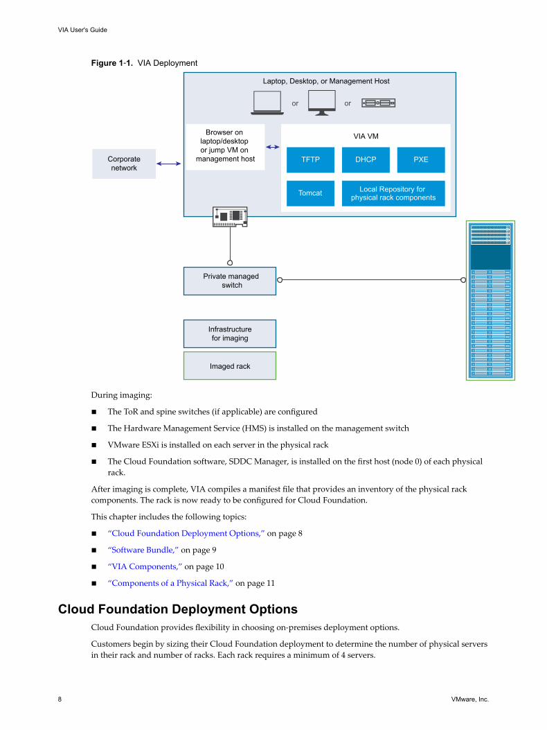
Figure 1‑1. VIA Deployment
Imaged rack
Infrastructurefor imaging
Laptop, Desktop, or Management Host
Private managed switch
VIA VM
or or
TFTP
Tomcat
DHCP PXE
Local Repository for physical rack components
Browser on laptop/desktop or jump VM on
management hostCorporatenetwork
During imaging:
n The ToR and spine switches (if applicable) are configured
n The Hardware Management Service (HMS) is installed on the management switch
n VMware ESXi is installed on each server in the physical rack
n The Cloud Foundation software, SDDC Manager, is installed on the first host (node 0) of each physicalrack.
After imaging is complete, VIA compiles a manifest file that provides an inventory of the physical rackcomponents. The rack is now ready to be configured for Cloud Foundation.
This chapter includes the following topics:
n “Cloud Foundation Deployment Options,” on page 8
n “Software Bundle,” on page 9
n “VIA Components,” on page 10
n “Components of a Physical Rack,” on page 11
Cloud Foundation Deployment OptionsCloud Foundation provides flexibility in choosing on-premises deployment options.
Customers begin by sizing their Cloud Foundation deployment to determine the number of physical serversin their rack and number of racks. Each rack requires a minimum of 4 servers.
VIA User's Guide
8 VMware, Inc.
Customers have two deployment options for Cloud Foundation
n Deploy the Cloud Foundation software on ready systems in your datacenter.
Customers can start with a ready system (set of qualified Virtual SAN nodes and switches) in theirdatacenter, wire it up, and deploy the Cloud Foundation software stack on the ready system. Forinformation on qualified hardware, see VMware Compatibility Guide.
n Purchase a fully integrated system that combines software and hardware from select VMware partners.
The partner works with a VMware representative to complete the Site Readiness document. Thistranslates into a bill of materials (BoM) consisting of both hardware and software components. With thisBoM in hand, the partner assembles the rack and images it. The partner then ships the system,consisting of physical racks, servers, server sub-components, power distribution units, switchinginfrastructure and the Cloud Foundation software, to customers.
Deploying VMware Cloud Foundation on Qualified Hardware(http://link.brightcove.com/services/player/bcpid2296383276001?bctid=ref:video_deploy_cloud_foundation_hardware)
Software BundleThe software bundle is a collection of all the software, configuration files, utilities, and tools used by VIA toimage a physical rack. It contains a manifest file that lists the contents of the bundle. The bundle is based ona hardware bill-of-materials (BoM), that includes specific servers, switch models, and their component levelconfigurations.
The bundle contains the following software:
n vSphere (vCenter Server and ESXi)
n NSX
n Virtual SAN
n vRealize Log Insight
n vRealize Operations
n SDDC Manager
n Platform Services Controller
n VMware Horizon with View
n App Volumes
See the VMware Cloud Foundation Release Notes for the software component versions.
Chapter 1 About VIA
VMware, Inc. 9
VIA ComponentsVIA uses multiple components to track and perform the imaging process. This section describes thesecomponents, but you do not need to perform any configuration on them.
DatabaseVIA stores information about all activities during an imaging run in an HSQLDB database. This includescurrent imaging information as well as the previous imaging status. All entities utilized by the imagingprocess are stored as an entry in the database. These entities include the software bundle, imagedcomponent, manifests, user information, and hardware information.
InventoryVIA maintains a bundle inventory and a rack inventory.
The bundle inventory is an input to the imaging activity, and is created by VIA before it begins an imagingrun. The bundle inventory is specific to a vendor and hardware type.
The rack inventory includes configuration details of the hardware imaged by VIA. The configuration detailsincludes credentials to access both the data and the management interfaces of the imaged hardware, as wellas the protocols to be used to access the interfaces of the imaged hardware.
ServicesIn order to handle disparate requests that may be required to service its components, VIA deploys multipleservices. Each service has a specific goal, and is instantiated based on the state of the imaging activity.
Bundle Inventory ServiceVIA deploys the bundle inventory service before starting an imaging activity. The service creates a bundleinventory using all the information in the bundle manifest. It ensures that the software bundle contains thefiles listed in the manifest and lists the manufacturer and hardware for which the bundle can be used.
The bundle inventory service includes a bundle manager and bundle controller. They manage the softwarebundles, mount the active bundle to be used for an imaging run, and set up TFTP and PXE Linuxconfiguration to image the servers.
Device Manifest ServiceThe device manifest service creates a new manifest file when an imaging activity is performed for the firsttime. It also tracks changes to the device status and stores hardware information for the rack components.
Imaging ServiceThe imaging service can start, stop, or cancel an imaging run. It tracks the imaging workflow and maintainsthe state of the imaging run as well as details about the device being imaged. Details being tracked includethe IP address of the device, imaging task being performed, status of the imaging task, and completion timeof the imaging task.
DHCP ServiceVIA deploys the DHCP service before starting an imaging run. The DHCP service discovers the physicalrack components and their PXE images using the DHCP Protocol. It keeps track of the IP addressesallocated to the devices to ensure that a device can be provided with the same IP address in case it needs tobe reimaged.
VIA User's Guide
10 VMware, Inc.
Cipher ServiceThe imaging service uses a cipher service to generate passwords to access the imaged rack components. Thecipher service ensures that each imaged component is always associated with a unique password. However,all ESXi hosts have the same password.
Rack Inventory ServiceThe rack inventory service is deployed when the components have been successfully imaged. It collectsaccess information for the imaged components such as connection protocol, IP address, and username andpassword and generates an inventory file. This inventory file is then transferred to the management switch.
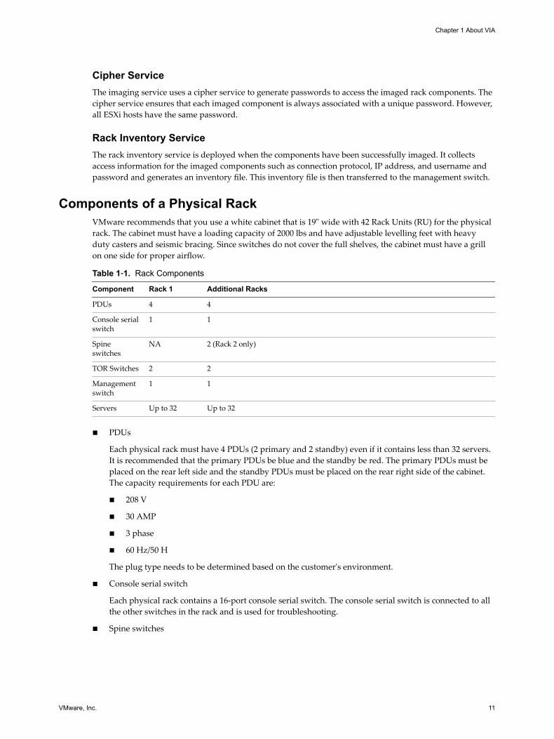
Components of a Physical RackVMware recommends that you use a white cabinet that is 19" wide with 42 Rack Units (RU) for the physicalrack. The cabinet must have a loading capacity of 2000 lbs and have adjustable levelling feet with heavyduty casters and seismic bracing. Since switches do not cover the full shelves, the cabinet must have a grillon one side for proper airflow.
Table 1‑1. Rack Components
Component Rack 1 Additional Racks
PDUs 4 4
Console serialswitch
1 1
Spineswitches
NA 2 (Rack 2 only)
TOR Switches 2 2
Managementswitch
1 1
Servers Up to 32 Up to 32
n PDUs
Each physical rack must have 4 PDUs (2 primary and 2 standby) even if it contains less than 32 servers.It is recommended that the primary PDUs be blue and the standby be red. The primary PDUs must beplaced on the rear left side and the standby PDUs must be placed on the rear right side of the cabinet.The capacity requirements for each PDU are:
n 208 V
n 30 AMP
n 3 phase
n 60 Hz/50 H
The plug type needs to be determined based on the customer's environment.
n Console serial switch
Each physical rack contains a 16-port console serial switch. The console serial switch is connected to allthe other switches in the rack and is used for troubleshooting.
n Spine switches
Chapter 1 About VIA
VMware, Inc. 11
Rack 2 in your Cloud Foundation system contains two 32 x 40 GE spine switches. These switchesconnect multiple racks by using uplinks from the Top of Rack switches.
Spine switches must not be connected to a corporate network. They are only used for ToR connectivitybetween physical racks.
n Top of Rack (ToR) switches
Each rack contains two 1RU 48-port 10 GE ToR switches with four 40 GE uplinks. Servers in each rackare connected to both ToRs. The ToRs on rack 1 connect Cloud Foundation to the corporate network.
n Management switch
Each rack contains a 1 GE management switch, which is used for IPMI access and access to the physicalswitches. The management ports of the ToR switches, Spine switches (on Rack 2 only) , and the physicalservers are connected to the management switch. The data ports of the ToR switches are also connectedto the management switch. This enables the management switch to monitor the data from the serversfrom both the management network as well as the data network.
The management switch provides out-of-band (OOB) connectivity for managing switches and servers.The hardware management service (HMS) runs on the management switch.
n Servers
VIA User's Guide
12 VMware, Inc.
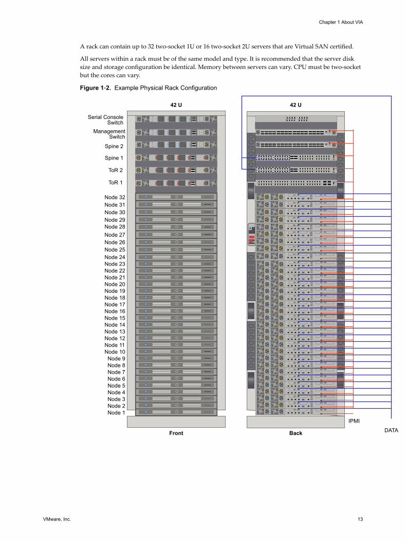
A rack can contain up to 32 two-socket 1U or 16 two-socket 2U servers that are Virtual SAN certified.
All servers within a rack must be of the same model and type. It is recommended that the server disksize and storage configuration be identical. Memory between servers can vary. CPU must be two-socketbut the cores can vary.
Figure 1‑2. Example Physical Rack Configuration
42 U
Back
42 U
Front
IPMIDATA
Node 24
Node 1Node 2Node 3Node 4Node 5Node 6Node 7Node 8Node 9
Node 10Node 11Node 12Node 13Node 14Node 15Node 16Node 17Node 18Node 19Node 20Node 21Node 22Node 23
Spine 2
Spine 1
ToR 2
ToR 1
ManagementSwitch
Serial ConsoleSwitch
Node 25
Node 28
Node 26Node 27
Node 29Node 30Node 31Node 32
Chapter 1 About VIA
VMware, Inc. 13

VIA User's Guide
14 VMware, Inc.
Before You Install VIA 2Before you install VIA, ensure that you have all of the required hardware components in place.
This chapter includes the following topics:
n “Requirements for VIA,” on page 15
n “Setting up your Environment,” on page 15
Requirements for VIAVIA requires the following infrastructure.
n You need a laptop/desktop or an ESXi host (called management host) to run the VIA VM.
A laptop works well for imaging a single rack while a management host is recommended if you areimaging multiple racks. The laptop need to be connected to the management switch of the rack beingimaged. If there are multiple racks to be imaged, this would mean physically moving the laptop forimaging each rack. The management host is connected to all the management switches through aninternal switch, so the connection to the rack being imaged can be managed remotely.
n Desktop or laptop (Windows or Mac) with 4 GB memory and a multi core processor to access thejump VM. A Windows laptop must have Workstation 8 or later and a Mac should have Fusion 4 orlater installed on it. You also need a network adapter, a cable, and a 4-port unmanaged switch.
n Management host - a standalone VMware vSphere ESXi 6.0 or later server to host the Windowsjump VM. The management host must have at least two NICs, with one NIC connected to thecorporate network and one NIC connected to the private network.
n If you are using a management host for imaging, you need a jump VM to access VIA
n Private managed switch. Private indicates that it is being used only by you. A managed switch providesthe ability to configure, manage, and monitor your LAN, which gives you greater control over how datatravels over the network and who has access to it.
Setting up your EnvironmentYou must inspect the components of the physical rack, verify cable connectivity, and validate BIOS settingsbefore beginning the imaging process.
Review the Bill Of Materials (BOM) from VMware and ensure there are no discrepancies between the BOMand the equipment being used.
VMware, Inc. 15
Rack PowerEnsure that rack power meets the following requirements.
n Verify that each device in the rack has a connection to each PDU.
n VMware recommends that you cable each server to the nearest power port so that the cable length canbe kept to a minimum. Length of power cables should be as follows.
n From the Physical Server: (9) .5m (3) 1m
n From the Top-of-Rack Switch: 1.5m
n From the Spine Switch: .5m
It is common for power cables within a rack to be longer than required. However, if excess cabling isnot managed properly, it may create electromagnetic interference. Avoid bundling of excess cables asthis may lead to the cables being damaged due to bending.
n The power connector from the PDU must match the power connector in the Site Readiness Assessment.
n Power cables must be seated properly from each device to the PDU.
n The cables connect the primary PDUs to the other components must be blue and the cables from thesecondary PDUs must be red.
n Power cables should not be in an area where there is a risk of touching sharp edges, excessive heat, orsubject to pinching between sliding rails.
Network CablesProper management of network cables promotes the elimination of crosstalk and interference, coolerperformance, improved maintenance, and easier upgrades. Incorrect cable management may result indamage or failure, which may lead to data transmission errors, performance issues, or system downtime.This section contains cable color and management recommendations. You can adapt the recommendationsto suit your environment.
Regardless of the number of servers in each rack, cables must be in place for 32 servers. Ideally, data andpower cables must be at opposite ends of the physical rack. If they are aggregated in a bundle or run parallelto each other, induction may introduce electromagnetic interference.
Cable ColorsUsing specific colors for cables from each device makes for easier troubleshooting.
n All cables from the management switch (except those going to the ToRs): yellow
n Management switch ports 49 and 50 going to the ToRs: black
n ToR 1 cables to servers: blue
n ToR 2 cables to servers: red
n ToR 1 and ToR 2 connections to spine switches: orange
n Console serial switch connections: grey
VIA User's Guide
16 VMware, Inc.
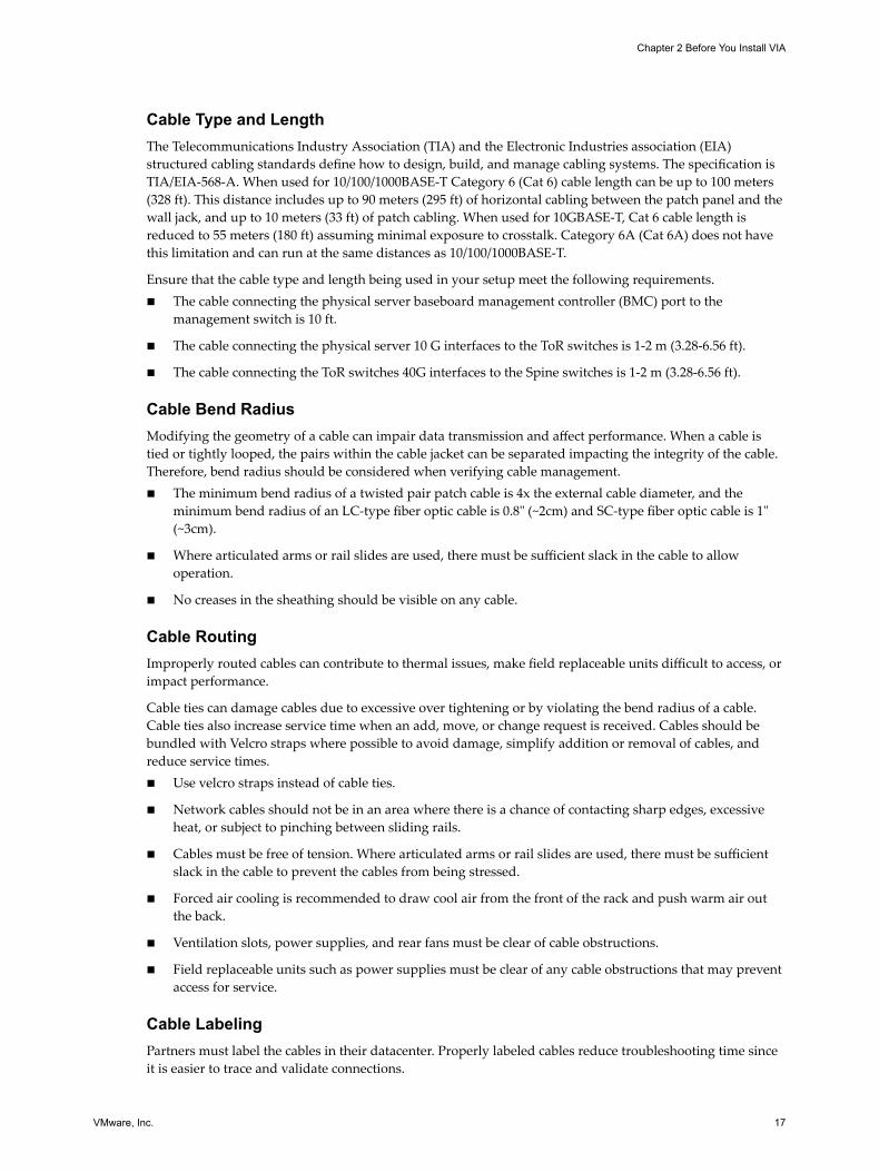
Cable Type and LengthThe Telecommunications Industry Association (TIA) and the Electronic Industries association (EIA)structured cabling standards define how to design, build, and manage cabling systems. The specification isTIA/EIA-568-A. When used for 10/100/1000BASE-T Category 6 (Cat 6) cable length can be up to 100 meters(328 ft). This distance includes up to 90 meters (295 ft) of horizontal cabling between the patch panel and thewall jack, and up to 10 meters (33 ft) of patch cabling. When used for 10GBASE-T, Cat 6 cable length isreduced to 55 meters (180 ft) assuming minimal exposure to crosstalk. Category 6A (Cat 6A) does not havethis limitation and can run at the same distances as 10/100/1000BASE-T.
Ensure that the cable type and length being used in your setup meet the following requirements.n The cable connecting the physical server baseboard management controller (BMC) port to the
management switch is 10 ft.
n The cable connecting the physical server 10 G interfaces to the ToR switches is 1-2 m (3.28-6.56 ft).
n The cable connecting the ToR switches 40G interfaces to the Spine switches is 1-2 m (3.28-6.56 ft).
Cable Bend RadiusModifying the geometry of a cable can impair data transmission and affect performance. When a cable istied or tightly looped, the pairs within the cable jacket can be separated impacting the integrity of the cable.Therefore, bend radius should be considered when verifying cable management.n The minimum bend radius of a twisted pair patch cable is 4x the external cable diameter, and the
minimum bend radius of an LC-type fiber optic cable is 0.8" (~2cm) and SC-type fiber optic cable is 1"(~3cm).
n Where articulated arms or rail slides are used, there must be sufficient slack in the cable to allowoperation.
n No creases in the sheathing should be visible on any cable.
Cable RoutingImproperly routed cables can contribute to thermal issues, make field replaceable units difficult to access, orimpact performance.
Cable ties can damage cables due to excessive over tightening or by violating the bend radius of a cable.Cable ties also increase service time when an add, move, or change request is received. Cables should bebundled with Velcro straps where possible to avoid damage, simplify addition or removal of cables, andreduce service times.n Use velcro straps instead of cable ties.
n Network cables should not be in an area where there is a chance of contacting sharp edges, excessiveheat, or subject to pinching between sliding rails.
n Cables must be free of tension. Where articulated arms or rail slides are used, there must be sufficientslack in the cable to prevent the cables from being stressed.
n Forced air cooling is recommended to draw cool air from the front of the rack and push warm air outthe back.
n Ventilation slots, power supplies, and rear fans must be clear of cable obstructions.
n Field replaceable units such as power supplies must be clear of any cable obstructions that may preventaccess for service.
Cable LabelingPartners must label the cables in their datacenter. Properly labeled cables reduce troubleshooting time sinceit is easier to trace and validate connections.
Chapter 2 Before You Install VIA
VMware, Inc. 17
Cable TestingCable testing ensures that the installed cabling links provide the transmission capability to support the datacommunication required.
Several tools are available for copper testing. Tests fall into three categories: Verification, Qualification, andCertification. Verification tools are used to perform basic continuity, cable length, and open connectionverification. Qualification tools can provide information that details the cable capabilities, e.g. supports10GBase-T. Certification tools determine whether the cable meets TIA standards such as TIA-568-B.
Options for testing SFP+ and QSFP+ cables are limited. Because handheld cable testers are not available,many network administrators typically reserve ports between two adjacent switches, then connect a suspectcable between active ports to determine if the cable is functional.
n Test cables from the physical server baseboard management controller (BMC) port and the managementswitch.
n Review the test print out to confirm that the cables passed the test.
n Cables from the physical server BMC port to the management switch must be seated properly.
n Cables from the physical server 10G interface to the ToR switches must be tested prior to installation.They must be seated properly.
n Each 10G interface must be connected to a separate ToR switch.
n Inter-switch SFP+ and QSFP+ cables must be tested prior to installation.
n Each 40G QSFP+ cable from the ToR switch must be connected to a separate Spine switch.
n There must be two 40G QSFP+ cable connections between each ToR switch and Spine switch.
n Inter-switch SFP+ and QSFP+ cables must be seated properly.
VIA User's Guide
18 VMware, Inc.
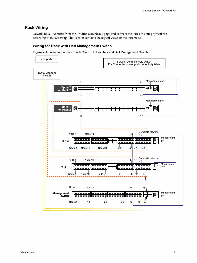
Rack WiringDownload VCF Wiremap from the Product Downloads page and connect the wires in your physical rackaccording to the wiremap. This section contains the logical views of the wiremaps.
Wiring for Rack with Dell Management SwitchFigure 2‑1. Wiremap for rack 1 with Cisco ToR Switches and Dell Management Switch
1
2
1
2
Spine 2on Rack 2
ToR 2
Managementswitch
Spine 1on Rack 2
ToR 1
16 switch serial console switch. For Connections, see port connectivity table
Management port
Corporate network
Management port
31
31
32
32
Management port
Node 1
Node 2 Node 12 Node 24 30
39
48
Management port
Node 1
Node 2 Node 12 Node 24 30 48
Node 1
Node 2 12 24 36 50
49
Management port
Jump VM
Privatе Managed Switch
41
42 48
Corporate network
Node 13
Node 13
Node 13
39
40
41
41
42
40 42
Chapter 2 Before You Install VIA
VMware, Inc. 19
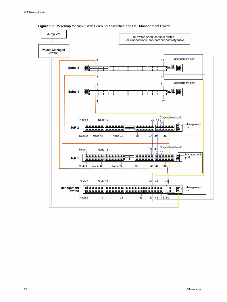
Figure 2‑2. Wiremap for rack 2 with Cisco ToR Switches and Dell Management Switch
Spine 2
ToR 2
Managementswitch
Spine 1
ToR 1
16 switch serial console switch. For Connections, see port connectivity table
Management port
Corporate network
Management port
31
31
32
32
Management port
Node 1
Node 2 Node 12 Node 24 30
39
48
Management port
Node 1
Node 2 Node 12 Node 24 30 48
Node 1
Node 2 12 24 36 50
49
Management port
Jump VM
Privatе Managed Switch
41
42 48
Corporate network
Node 13
Node 13
Node 13
39
40
40
41
41
42
42
43
44
3
4
3
4
VIA User's Guide
20 VMware, Inc.
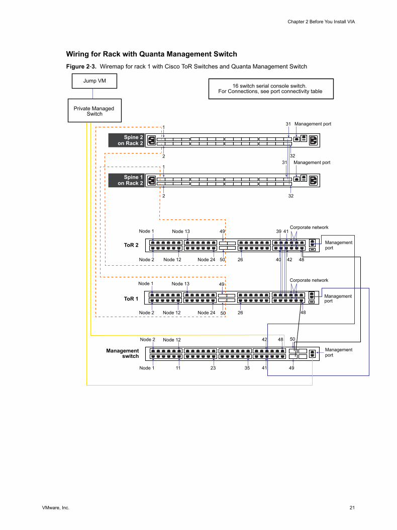
Wiring for Rack with Quanta Management SwitchFigure 2‑3. Wiremap for rack 1 with Cisco ToR Switches and Quanta Management Switch
ToR 2
Managementswitch
ToR 1
16 switch serial console switch. For Connections, see port connectivity table
Management port
Corporate network
Management port
1
2
Management port
Node 1
Node 2 Node 12 Node 24 26
39
Management port
Node 1
Node 2 Node 12 Node 24 26
Node 2
Node 1 11 23 35 49
48
Management port
Jump VM
Private Managed Switch
42
41
Corporate network
Node 13
Node 13
Node 12
41
32
31
32
31
50
49
50
49
48
50
484240
1
2
Spine 2on Rack 2
Spine 1on Rack 2
Chapter 2 Before You Install VIA
VMware, Inc. 21
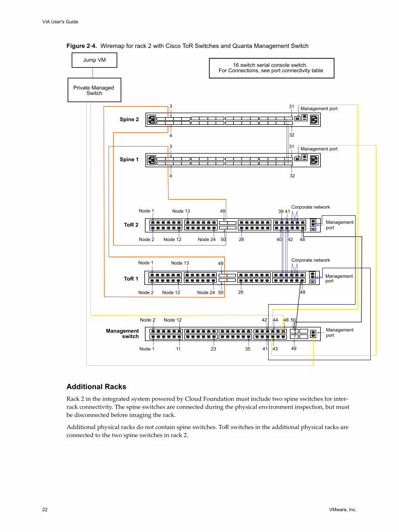
Figure 2‑4. Wiremap for rack 2 with Cisco ToR Switches and Quanta Management Switch
Spine 2
ToR 2
Managementswitch
Spine 1
ToR 1
16 switch serial console switch. For Connections, see port connectivity table
Management port
Corporate network
Management port
3
4
Management port
Node 1
Node 2 Node 12 Node 24 26
39
48
Management port
Node 1
Node 2 Node 12 Node 24 26
Node 2
Node 1 11 23 35 49
48
Management port
Jump VM
Private Managed Switch
42
41
Corporate network
Node 13
Node 13
Node 12
41
42
32
31
32
31
50
49
50
49
40
48
50 44
43
3
4
Additional RacksRack 2 in the integrated system powered by Cloud Foundation must include two spine switches for inter-rack connectivity. The spine switches are connected during the physical environment inspection, but mustbe disconnected before imaging the rack.
Additional physical racks do not contain spine switches. ToR switches in the additional physical racks areconnected to the two spine switches in rack 2.
VIA User's Guide
22 VMware, Inc.
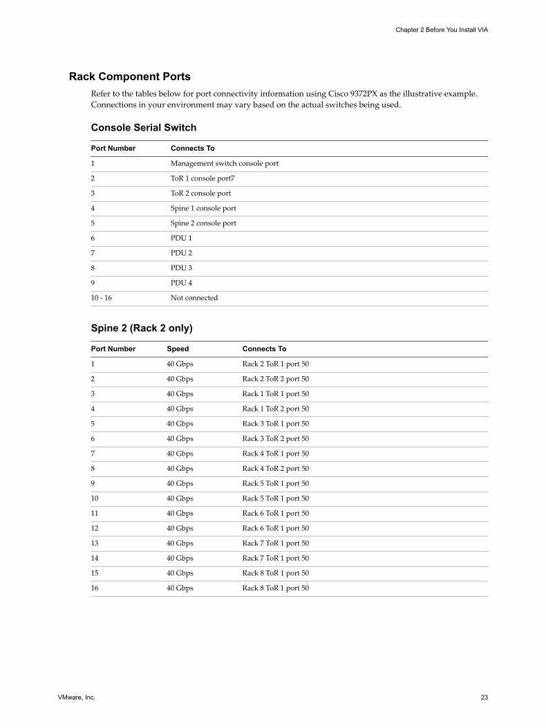
Rack Component PortsRefer to the tables below for port connectivity information using Cisco 9372PX as the illustrative example.Connections in your environment may vary based on the actual switches being used.
Console Serial Switch
Port Number Connects To
1 Management switch console port
2 ToR 1 console port7
3 ToR 2 console port
4 Spine 1 console port
5 Spine 2 console port
6 PDU 1
7 PDU 2
8 PDU 3
9 PDU 4
10 - 16 Not connected
Spine 2 (Rack 2 only)
Port Number Speed Connects To
1 40 Gbps Rack 2 ToR 1 port 50
2 40 Gbps Rack 2 ToR 2 port 50
3 40 Gbps Rack 1 ToR 1 port 50
4 40 Gbps Rack 1 ToR 2 port 50
5 40 Gbps Rack 3 ToR 1 port 50
6 40 Gbps Rack 3 ToR 2 port 50
7 40 Gbps Rack 4 ToR 1 port 50
8 40 Gbps Rack 4 ToR 2 port 50
9 40 Gbps Rack 5 ToR 1 port 50
10 40 Gbps Rack 5 ToR 1 port 50
11 40 Gbps Rack 6 ToR 1 port 50
12 40 Gbps Rack 6 ToR 1 port 50
13 40 Gbps Rack 7 ToR 1 port 50
14 40 Gbps Rack 7 ToR 1 port 50
15 40 Gbps Rack 8 ToR 1 port 50
16 40 Gbps Rack 8 ToR 1 port 50
Chapter 2 Before You Install VIA
VMware, Inc. 23
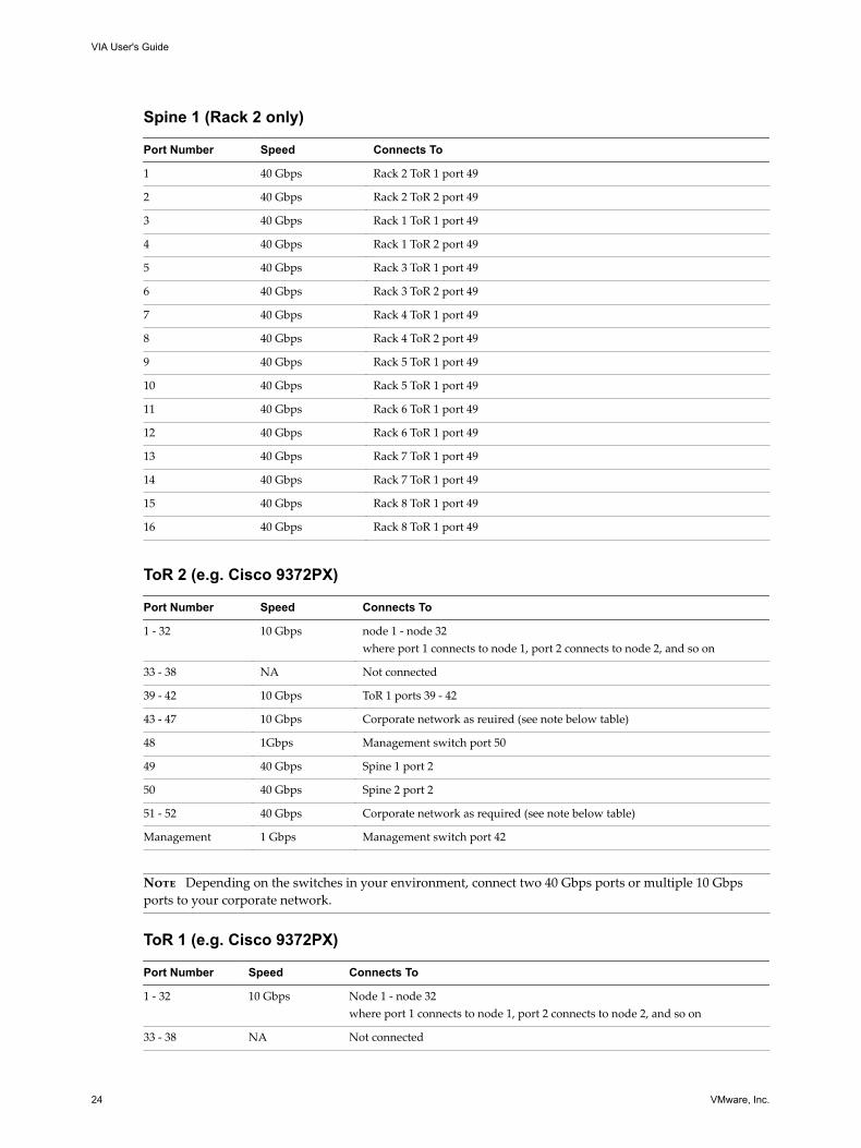
Spine 1 (Rack 2 only)
Port Number Speed Connects To
1 40 Gbps Rack 2 ToR 1 port 49
2 40 Gbps Rack 2 ToR 2 port 49
3 40 Gbps Rack 1 ToR 1 port 49
4 40 Gbps Rack 1 ToR 2 port 49
5 40 Gbps Rack 3 ToR 1 port 49
6 40 Gbps Rack 3 ToR 2 port 49
7 40 Gbps Rack 4 ToR 1 port 49
8 40 Gbps Rack 4 ToR 2 port 49
9 40 Gbps Rack 5 ToR 1 port 49
10 40 Gbps Rack 5 ToR 1 port 49
11 40 Gbps Rack 6 ToR 1 port 49
12 40 Gbps Rack 6 ToR 1 port 49
13 40 Gbps Rack 7 ToR 1 port 49
14 40 Gbps Rack 7 ToR 1 port 49
15 40 Gbps Rack 8 ToR 1 port 49
16 40 Gbps Rack 8 ToR 1 port 49
ToR 2 (e.g. Cisco 9372PX)
Port Number Speed Connects To
1 - 32 10 Gbps node 1 - node 32where port 1 connects to node 1, port 2 connects to node 2, and so on
33 - 38 NA Not connected
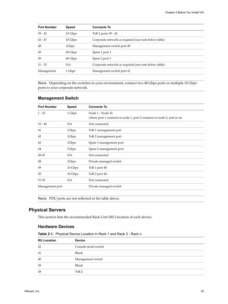
39 - 42 10 Gbps ToR 1 ports 39 - 42
43 - 47 10 Gbps Corporate network as reuired (see note below table)
48 1Gbps Management switch port 50
49 40 Gbps Spine 1 port 2
50 40 Gbps Spine 2 port 2
51 - 52 40 Gbps Corporate network as required (see note below table)
Management 1 Gbps Management switch port 42
Note Depending on the switches in your environment, connect two 40 Gbps ports or multiple 10 Gbpsports to your corporate network.
ToR 1 (e.g. Cisco 9372PX)
Port Number Speed Connects To
1 - 32 10 Gbps Node 1 - node 32where port 1 connects to node 1, port 2 connects to node 2, and so on
33 - 38 NA Not connected
VIA User's Guide
24 VMware, Inc.
Port Number Speed Connects To
39 - 42 10 Gbps ToR 2 ports 39 - 42
43 - 47 10 Gbps Corporate network as required (see note below table)
48 1Gbps Management switch port 49
49 40 Gbps Spine 1 port 1
50 40 Gbps Spine 2 port 1
51 - 52 NA Corporate network as required (see note below table)
Management 1 Gbps Management switch port 41
Note Depending on the switches in your environment, connect two 40 Gbps ports or multiple 10 Gbpsports to your corporate network.
Management Switch
Port Number Speed Connects To
1 - 32 1 Gbps Node 1 - Node 32where port 1 connects to node 1, port 2 connects to node 2, and so on
33 - 40 NA Not connected
41 1Gbps ToR 1 management port
42 1Gbps ToR 2 management port
43 1Gbps Spine 1 management port
44 1Gbps Spine 2 management port
45-47 NA Not connected
48 1Gbps Private managed switch
49 10 Gbps ToR 1 port 48
50 10 Gbps ToR 2 port 48
51-52 NA Not connected
Management port Private managed switch
Note PDU ports are not reflected in the table above.
Physical ServersThis section lists the recommended Rack Unit (RU) location of each device.
Hardware DevicesTable 2‑1. Physical Device Location in Rack 1 and Rack 3 - Rack n
RU Location Device
42 Console serial switch
41 Blank
40 Management switch
39 Blank
38 ToR 2
Chapter 2 Before You Install VIA
VMware, Inc. 25
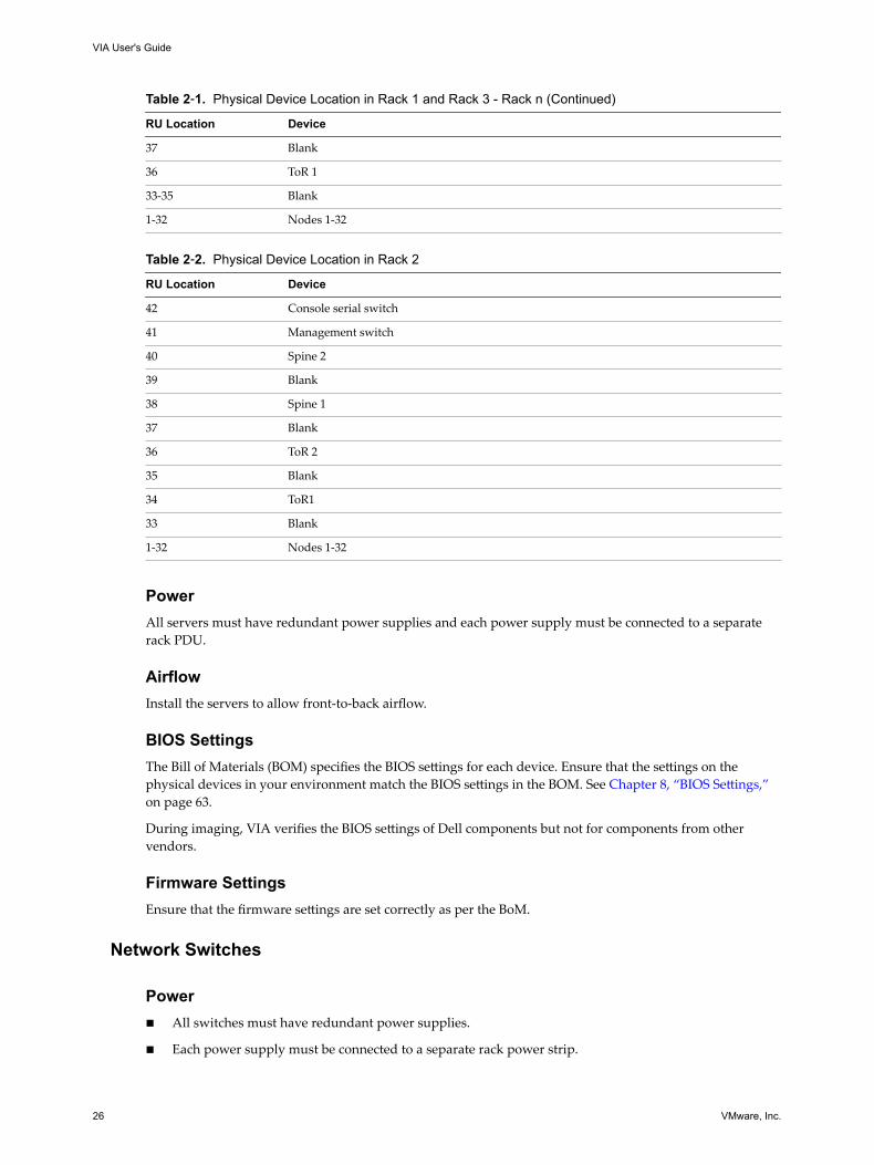
Table 2‑1. Physical Device Location in Rack 1 and Rack 3 - Rack n (Continued)
RU Location Device
37 Blank
36 ToR 1
33-35 Blank
1-32 Nodes 1-32
Table 2‑2. Physical Device Location in Rack 2
RU Location Device
42 Console serial switch
41 Management switch
40 Spine 2
39 Blank
38 Spine 1
37 Blank
36 ToR 2
35 Blank
34 ToR1
33 Blank
1-32 Nodes 1-32
PowerAll servers must have redundant power supplies and each power supply must be connected to a separaterack PDU.
AirflowInstall the servers to allow front-to-back airflow.
BIOS SettingsThe Bill of Materials (BOM) specifies the BIOS settings for each device. Ensure that the settings on thephysical devices in your environment match the BIOS settings in the BOM. See Chapter 8, “BIOS Settings,”on page 63.
During imaging, VIA verifies the BIOS settings of Dell components but not for components from othervendors.
Firmware SettingsEnsure that the firmware settings are set correctly as per the BoM.
Network Switches
Powern All switches must have redundant power supplies.
n Each power supply must be connected to a separate rack power strip.
VIA User's Guide
26 VMware, Inc.
AirflowSwitches must be installed to allow front-to-back airflow.
ONIE versionEnsure that the correct ONIE version is installed as per the BOM.
Laptop or Management HostYou need a laptop or management host where you install VIA.
LaptopYou need a desktop or laptop (Windows or Mac) with 4 GB memory and a multi core processor to access thejump VM. A Windows laptop must have Workstation 8 or later and a Mac should have Fusion 4 or laterinstalled on it. You also need a network adapter, a cable, and a 4-port unmanaged switch.
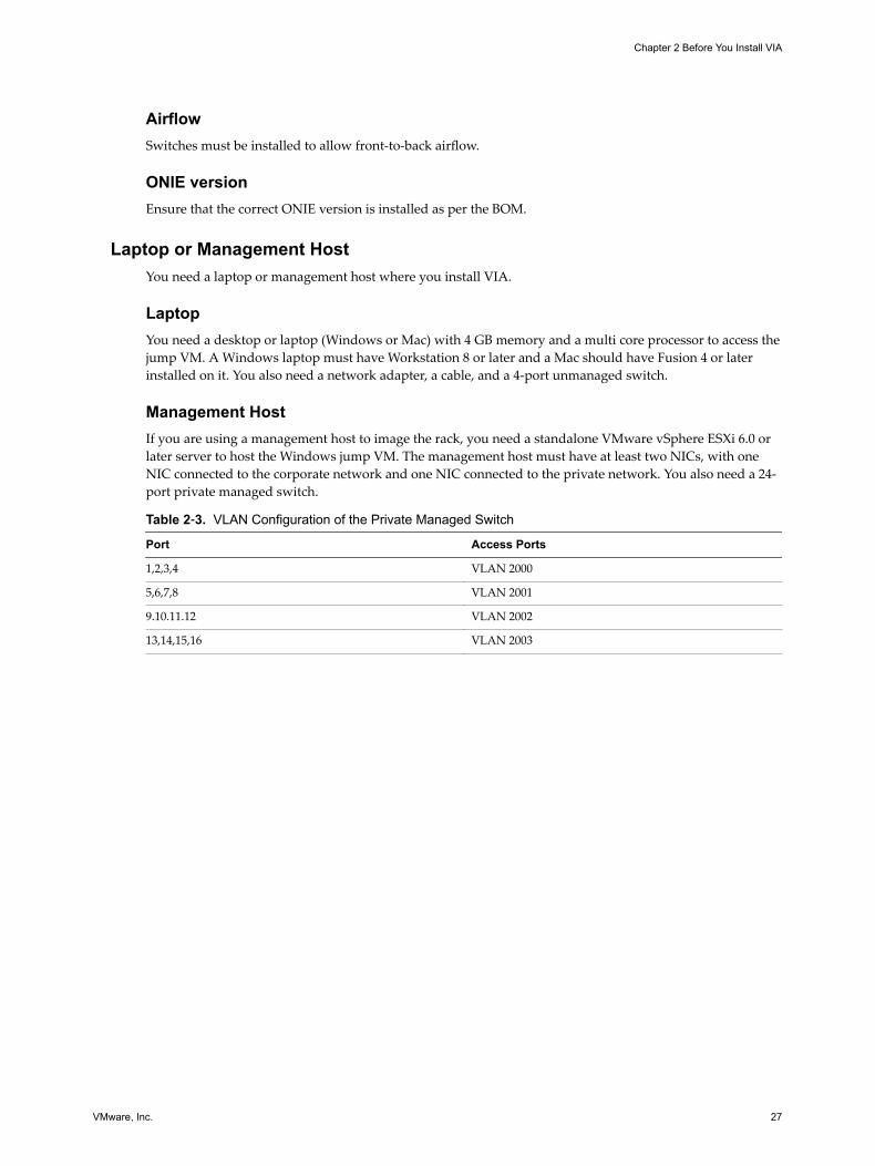
Management HostIf you are using a management host to image the rack, you need a standalone VMware vSphere ESXi 6.0 orlater server to host the Windows jump VM. The management host must have at least two NICs, with oneNIC connected to the corporate network and one NIC connected to the private network. You also need a 24-port private managed switch.
Table 2‑3. VLAN Configuration of the Private Managed Switch
Port Access Ports
1,2,3,4 VLAN 2000
5,6,7,8 VLAN 2001
9.10.11.12 VLAN 2002
13,14,15,16 VLAN 2003
Chapter 2 Before You Install VIA
VMware, Inc. 27
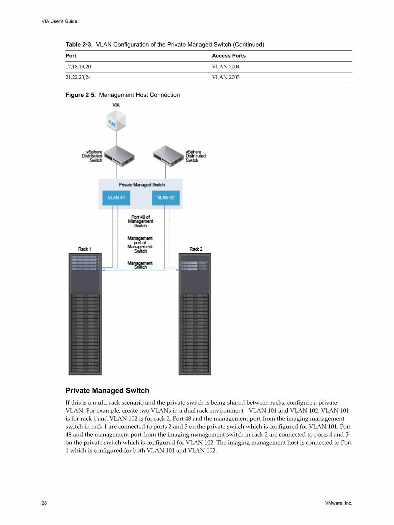
Table 2‑3. VLAN Configuration of the Private Managed Switch (Continued)
Port Access Ports
17,18,19,20 VLAN 2004
21,22,23,24 VLAN 2005
Figure 2‑5. Management Host Connection
Private Managed SwitchIf this is a multi-rack scenario and the private switch is being shared between racks, configure a privateVLAN. For example, create two VLANs in a dual rack environment - VLAN 101 and VLAN 102. VLAN 101is for rack 1 and VLAN 102 is for rack 2. Port 48 and the management port from the imaging managementswitch in rack 1 are connected to ports 2 and 3 on the private switch which is configured for VLAN 101. Port48 and the management port from the imaging management switch in rack 2 are connected to ports 4 and 5on the private switch which is configured for VLAN 102. The imaging management host is connected to Port1 which is configured for both VLAN 101 and VLAN 102.
VIA User's Guide
28 VMware, Inc.
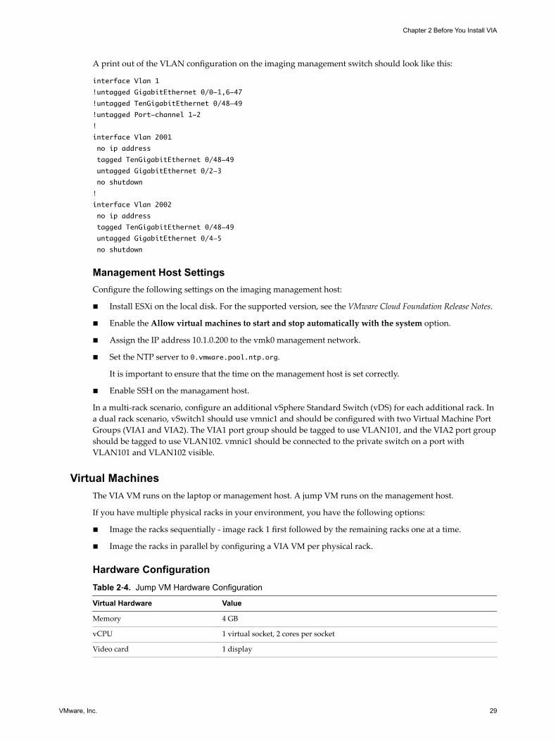
A print out of the VLAN configuration on the imaging management switch should look like this:
interface Vlan 1
!untagged GigabitEthernet 0/0-1,6-47
!untagged TenGigabitEthernet 0/48-49
!untagged Port-channel 1-2
!
interface Vlan 2001
no ip address
tagged TenGigabitEthernet 0/48-49
untagged GigabitEthernet 0/2-3
no shutdown
!
interface Vlan 2002
no ip address
tagged TenGigabitEthernet 0/48-49
untagged GigabitEthernet 0/4-5
no shutdown
Management Host SettingsConfigure the following settings on the imaging management host:
n Install ESXi on the local disk. For the supported version, see the VMware Cloud Foundation Release Notes.
n Enable the Allow virtual machines to start and stop automatically with the system option.
n Assign the IP address 10.1.0.200 to the vmk0 management network.
n Set the NTP server to 0.vmware.pool.ntp.org.
It is important to ensure that the time on the management host is set correctly.
n Enable SSH on the managament host.
In a multi-rack scenario, configure an additional vSphere Standard Switch (vDS) for each additional rack. Ina dual rack scenario, vSwitch1 should use vmnic1 and should be configured with two Virtual Machine PortGroups (VIA1 and VIA2). The VIA1 port group should be tagged to use VLAN101, and the VIA2 port groupshould be tagged to use VLAN102. vmnic1 should be connected to the private switch on a port withVLAN101 and VLAN102 visible.
Virtual MachinesThe VIA VM runs on the laptop or management host. A jump VM runs on the management host.
If you have multiple physical racks in your environment, you have the following options:
n Image the racks sequentially - image rack 1 first followed by the remaining racks one at a time.
n Image the racks in parallel by configuring a VIA VM per physical rack.
Hardware ConfigurationTable 2‑4. Jump VM Hardware Configuration
Virtual Hardware Value
Memory 4 GB
vCPU 1 virtual socket, 2 cores per socket
Video card 1 display
Chapter 2 Before You Install VIA
VMware, Inc. 29
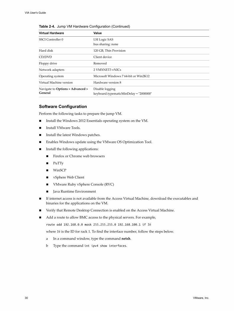
Table 2‑4. Jump VM Hardware Configuration (Continued)
Virtual Hardware Value
SSCI Controller 0 LSI Logic SASbus sharing: none
Hard disk 120 GB, Thin Provision
CD/DVD Client device
Floppy drive Removed
Network adapters 2 VMXNET3 vNICs
Operating system Microsoft Windows 7 64-bit or Win2K12
Virtual Machine version Hardware version 8
Navigate to Options > Advanced >General
Disable loggingkeyboard.typematicMinDelay = "2000000"
Software ConfigurationPerform the following tasks to prepare the jump VM.
n Install the Windows 2012 Essentials operating system on the VM.
n Install VMware Tools.
n Install the latest Windows patches.
n Enables Windows update using the VMware OS Optimization Tool.
n Install the following applications:
n Firefox or Chrome web browsers
n PuTTy
n WinSCP
n vSphere Web Client
n VMware Ruby vSphere Console (RVC)
n Java Runtime Environment
n If internet access is not available from the Access Virtual Machine, download the executables andbinaries for the applications on the VM.
n Verify that Remote Desktop Connection is enabled on the Access Virtual Machine.
n Add a route to allow BMC access to the physical servers. For example,
route add 192.168.0.0 mask 255.255.255.0 192.168.100.1 if 16
where 16 is the ID for rack 1. To find the interface number, follow the steps below.
a In a command window, type the command netsh.
b Type the command int ipv4 show interfaces.
VIA User's Guide
30 VMware, Inc.
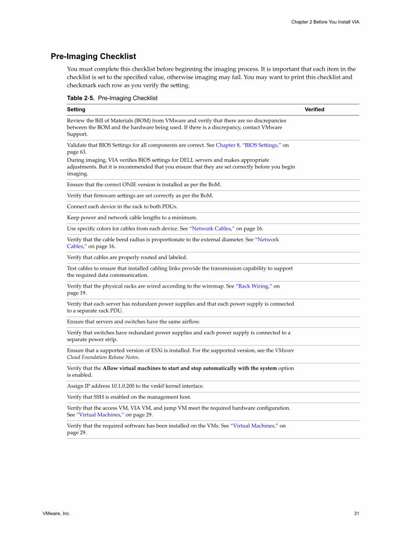
Pre-Imaging ChecklistYou must complete this checklist before beginning the imaging process. It is important that each item in thechecklist is set to the specified value, otherwise imaging may fail. You may want to print this checklist andcheckmark each row as you verify the setting.
Table 2‑5. Pre-Imaging Checklist
Setting Verified
Review the Bill of Materials (BOM) from VMware and verify that there are no discrepanciesbetween the BOM and the hardware being used. If there is a discrepancy, contact VMwareSupport.
Validate that BIOS Settings for all components are correct. See Chapter 8, “BIOS Settings,” onpage 63.During imaging, VIA verifies BIOS settings for DELL servers and makes appropriateadjustments. But it is recommended that you ensure that they are set correctly before you beginimaging.
Ensure that the correct ONIE version is installed as per the BoM.
Verify that firmware settings are set correctly as per the BoM.
Connect each device in the rack to both PDUs.
Keep power and network cable lengths to a minimum.
Use specific colors for cables from each device. See “Network Cables,” on page 16.
Verify that the cable bend radius is proportionate to the external diameter. See “NetworkCables,” on page 16.
Verify that cables are properly routed and labeled.
Test cables to ensure that installed cabling links provide the transmission capability to supportthe required data communication.
Verify that the physical racks are wired according to the wiremap. See “Rack Wiring,” onpage 19.
Verify that each server has redundant power supplies and that each power supply is connectedto a separate rack PDU.
Ensure that servers and switches have the same airflow.
Verify that switches have redundant power supplies and each power supply is connected to aseparate power strip.
Ensure that a supported version of ESXi is installed. For the supported version, see the VMwareCloud Foundation Release Notes.
Verify that the Allow virtual machines to start and stop automatically with the system optionis enabled.
Assign IP address 10.1.0.200 to the vmk0 kernel interface.
Verify that SSH is enabled on the management host.
Verify that the access VM, VIA VM, and jump VM meet the required hardware configuration.See “Virtual Machines,” on page 29.
Verify that the required software has been installed on the VMs. See “Virtual Machines,” onpage 29.
Chapter 2 Before You Install VIA
VMware, Inc. 31

VIA User's Guide
32 VMware, Inc.
Installing VIA 3You can install VIA on a desktop, laptop, or an ESXi host, also referred to as the management host. A laptopor desktop is recommended when you are imaging a single rack. A management host is better suited for anenvironment where you have several physical racks in your datacenter.
This chapter includes the following topics:
n “Installing VIA on a Laptop or Desktop,” on page 33
n “Installing VIA on a Management Host,” on page 34
Installing VIA on a Laptop or DesktopVIA is a virtual appliance. After you install the VIA VM on your laptop, you copy the software bundle to theVIA VM. You can then access the VIA user interface through a browser on the laptop.
Prerequisites
n Ensure that you have the infrastructure for VIA available and that you have set up your physicalenvironment as described in Chapter 2, “Before You Install VIA,” on page 15.
n Download the VIA OVF file, Cloud Foundation software bundle, and the md5sum file on the laptop ordesktop.
Procedure
1 Connect one port of the network adapter to your laptop and one port to the unmanaged switch.
2 Connect two ports of the unmanaged switch as follows:
n one port to the ethernet management port of the management switch
n one port to port 48 of the management switch
3 Deploy the VIA OVF file on your laptop.
Follow the wizard prompts to specify where to save the OVF file and accept the license agreement.
4 Configure time settings on the laptop.
5 Upload the Cloud Foundation software bundle on to the VIA VM by pointing the CD /DVD drive to thebundle ISO. Ensure that the CD/DVD drive is connected.
6 Configure network settings on the laptop.
a Connect one NIC on the laptop to the corporate network and the other to the unmanaged switch.
b Manually assign a static IP address to the laptop in the range 192.168.100.151 to 192.168.100.199.
VMware, Inc. 33
This allows for separation of network traffic between the corporate network and the private networkthat is established between the physical rack and VIA. It also helps ensure that the DHCP service whichis part of is VIA is confined to the private network between the physical rack and VIA.
7 For the browser on the laptop that will be used to access VIA, make the following selections.
n In Network Connection, disable the proxy.
n Select Auto-detect proxy settings for this network so that the browser detects the proxy settingsfor your network.
8 Ensure that you can ping the VIA VM (IP address is 192.168.100.2) from the laptop.
9 Power on the VIA VM.
10 Ensure that you can ping the management switch (IP address 192.168.100.1) from the VIA VM.
Since the management switch is the first component to be imaged, the VIA VM must be able to talk tothe management switch.
What to do next
Open a web browser on the laptop and type the following URL to connect to VIA:
http://192.168.100.2:8080/via/
Installing VIA on a Management Host
Prerequisites
n Ensure that you have the infrastructure for VIA available and that you have set up your physicalenvironment as described in Chapter 2, “Before You Install VIA,” on page 15.
n Download the VIA OVF file, Cloud Foundation software bundle, and the md5sum file on your local filesystem.
Procedure
1 Deploy the VIA OVF file on the management host.
a Login to the vSphere Web Client on the management host.
b Right-click the management host and click Deploy OVF Template.
c In source location, select Local file. Click Browse and select the VIA OVF from your local filesystem.
d Click Next.
e Review the OVF file details and click Next.
f Accept the OVF license agreements and click Next.
g Specify a name and location for the OVF and click Next.
h Select a resource and click Next.
i Select the disk format to store the VIA disks and the datastore to store the deployed OVF templateand click Next.
j On the Setup networks page, connect VIA to the private switch connected to rack 1.
k Review the deployment details and click Finish.
2 Copy the Cloud Foundation bundle to the management host.
a On the management host, create a single datastore named datastore1.
VIA User's Guide
34 VMware, Inc.

b In datastore1, create a folder named ISO bundle and copy the Cloud Foundation bundle file to thisfolder.
3 Configure time settings on the management host.
a In the vSphere Web Client, navigate to the management host in the vSphere inventory.
b Select Manage and then select Settings.
c Under System, select Time configuration and click Edit.
d Select Manually configure the date and time on this host.
e Set the time and date manually.
f Click OK.
4 Upload the software bundle on to the VIA VM.
a Right-click the VIA VM and select Edit Settings.
b Click the Hardware tab and select the CD/DVD drive.
c Select the Connected check box to connect the CD.
d Select Connect at power on so that the CD-ROM drive is connected when the virtual machinestarts.
e Select Datastore ISO under Device Type.
f Click Select, browse to the ISO Bundle folder in datastore1 on the management host, and select thebundle.
g Click OK.
5 Create a VM on the management host to serve as the jump VM.
Connect one NIC on the jump VM to the
network and the other to the private managed switch.
The jump VM must have a static IP address. The IP range 192.168.100.151 to 192.168.100.199 is usuallyavailable for the jump VM. Verify the address that you want to use against the via.properties file inthe bundle ISO to avoid any conflict.
This allows for separation of network traffic between the datacenter network and the private networkthat is established between the physical rack and VIA. It also helps ensure that the DHCP service whichis part of is VIA is confined to the private network between the physical rack and VIA.
6 Copy the md5sum file on the jump VM.
7 For the browser on the jump VM that will be used to access VIA, make the following selections.
n In Network Connection, disable the proxy.
n Select Auto-detect proxy settings for this network so that the browser detects the proxy settingsfor your network.
8 Ensure that you can ping the VIA VM (IP address is 192.168.100.2) from the jump VM.
If you cannot ping the VIA VM, check the route on the jump VM.
9 Power on the VIA VM.
10 Ensure that you can ping the management switch (IP address 192.168.100.1) from the VIA VM.
Since the management switch is the first component to be imaged, the VIA VM must be able to talk tothe management switch.
Chapter 3 Installing VIA
VMware, Inc. 35

What to do next
Open a web browser and type the following URL to connect to VIA:
http://192.168.100.2:8080/via/
VIA User's Guide
36 VMware, Inc.
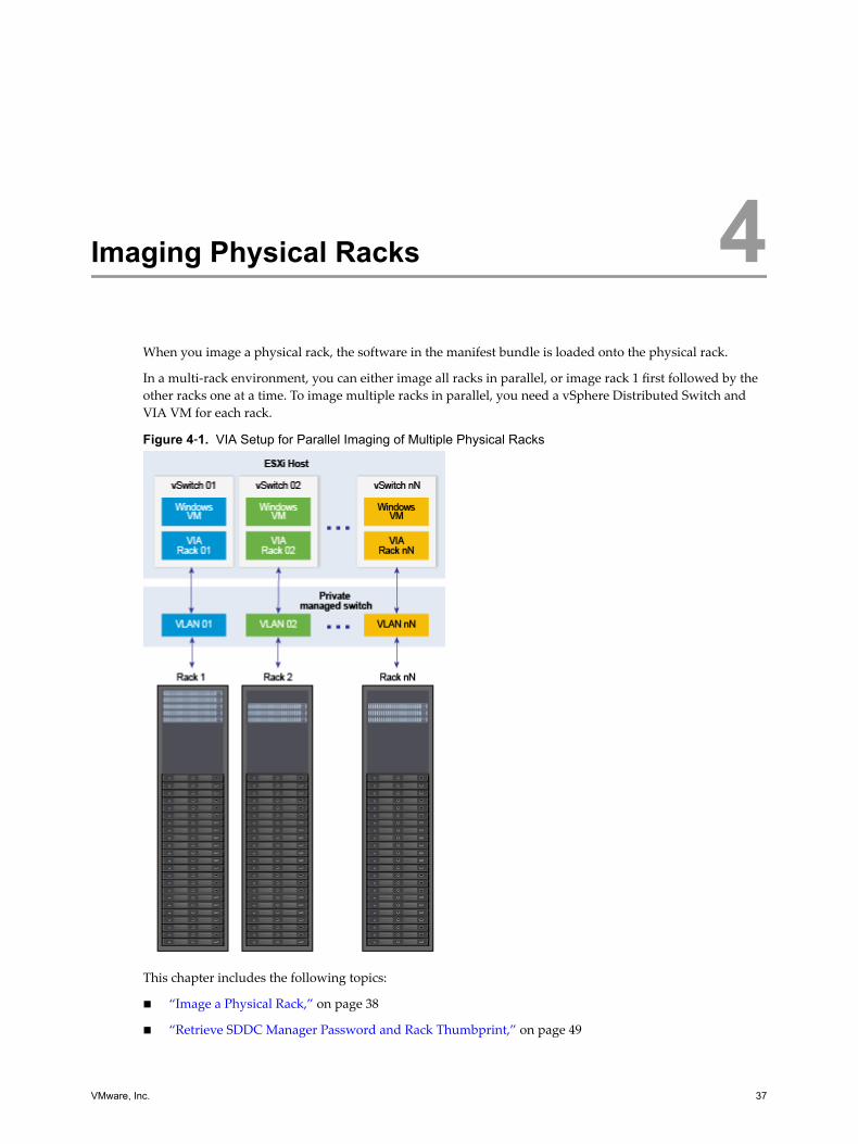
Imaging Physical Racks 4When you image a physical rack, the software in the manifest bundle is loaded onto the physical rack.
In a multi-rack environment, you can either image all racks in parallel, or image rack 1 first followed by theother racks one at a time. To image multiple racks in parallel, you need a vSphere Distributed Switch andVIA VM for each rack.
Figure 4‑1. VIA Setup for Parallel Imaging of Multiple Physical Racks
This chapter includes the following topics:
n “Image a Physical Rack,” on page 38
n “Retrieve SDDC Manager Password and Rack Thumbprint,” on page 49
VMware, Inc. 37
n “Resume Imaging,” on page 50
n “Image Additional Racks,” on page 52
Image a Physical RackVIA images the rack components in a pre-determined order, which is determined by the availability ofnetwork route to the different components of the rack. All switches are imaged first. This enables VIA toaccess the servers through the switches for imaging. The imaging order is as follows.
1 Management switch
The management switch is the main access gateway through which the Cloud Foundation managementdata is routed. The management ports of the ToR switches, Spine switches, and the physical servers areconnected to the management switch. The data ports of the ToR switches are also connected to themanagement switch. This enables VIA to communicate with the servers over both management anddata network through the management switch. VIA is also connected to the rack through a designatedport on the management switch. It is therefore required that the management switch is the firstcomponent imaged by VIA in order to obtain access to the other components of the rack. VIA currentlyuses an IPMI connection to image the management switch.
2 Spine switches (rack 2 only) and ToR switches
Spine and ToR switches are imaged in parallel.
Spine switches inter-connect multiple racks enabling a scale out architecture for the datacenter. Theycreate an stretched L2 backplane between racks.
ToR switches provide connectivity to servers in each rack out to spine switches. The first pair of ToRswitches provide connectivity to your datacenter network.
3 Servers
The management ports on the servers become accessible to the management switch during the course ofimaging/configuration, which in turn make the management ports accessible to VIA through themanagement switch. Once all the switches are imaged and configured, the data ports of the serversbecome accessible to VIA through the ToR switches, which then proceeds to image the servers inparallel.
For each component that is being imaged, the following tasks are performed.
1 Discovery
Rack components are discovered using the DHCP service running on the VIA VM. The DHCP Serviceuses the device type information to identify the device being discovered. Apart from the device typeinformation, the DHCP service also uses hardware vendor specific strings to determine whether theswitch being imaged is a management, ToR, or Spine switch.
The first component to be discovered is the management switch. The DHCP service hands out a pre-determined IP address for the management switch followed by a PXE image specific to themanagement switch.
After the management switch is imaged, the ToR and Spine switches are discovered and imaged. Themanagement switch also discovers the IPMI network of the servers. This allows VIA to initiate imagingof the servers. The ToR switch enables discovery of the data network of the servers which is used toreceive the installation image delivered by the DHCP service.
2 Image installation
Image installation refers to installing software on the components to make them operational. Thesoftware depends on the component type - an Operating System for switches and a Hypervisor forservers.
VIA User's Guide
38 VMware, Inc.
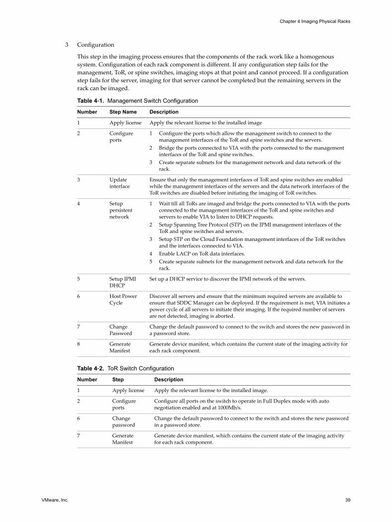
3 Configuration
This step in the imaging process ensures that the components of the rack work like a homogenoussystem. Configuration of each rack component is different. If any configuration step fails for themanagement, ToR, or spine switches, imaging stops at that point and cannot proceed. If a configurationstep fails for the server, imaging for that server cannot be completed but the remaining servers in therack can be imaged.
Table 4‑1. Management Switch Configuration
Number Step Name Description
1 Apply license Apply the relevant license to the installed image
2 Configureports
1 Configure the ports which allow the management switch to connect to themanagement interfaces of the ToR and spine switches and the servers.
2 Bridge the ports connected to VIA with the ports connected to the managementinterfaces of the ToR and spine switches.
3 Create separate subnets for the management network and data network of therack.
3 Updateinterface
Ensure that only the management interfaces of ToR and spine switches are enabledwhile the management interfaces of the servers and the data network interfaces of theToR switches are disabled before initiating the imaging of ToR switches.
4 Setuppersistentnetwork
1 Wait till all ToRs are imaged and bridge the ports connected to VIA with the portsconnected to the management interfaces of the ToR and spine switches andservers to enable VIA to listen to DHCP requests.
2 Setup Spanning Tree Protocol (STP) on the IPMI management interfaces of theToR and spine switches and servers.
3 Setup STP on the Cloud Foundation management interfaces of the ToR switchesand the interfaces connected to VIA.
4 Enable LACP on ToR data interfaces.5 Create separate subnets for the management network and data network for the
rack.
5 Setup IPMIDHCP
Set up a DHCP service to discover the IPMI network of the servers.
6 Host PowerCycle
Discover all servers and ensure that the minimum required servers are available toensure that SDDC Manager can be deployed. If the requirement is met, VIA initiates apower cycle of all servers to initiate their imaging. If the required number of serversare not detected, imaging is aborted.
7 ChangePassword
Change the default password to connect to the switch and stores the new password ina password store.
8 GenerateManifest
Generate device manifest, which contains the current state of the imaging activity foreach rack component.
Table 4‑2. ToR Switch Configuration
Number Step Description
1 Apply license Apply the relevant license to the installed image.
2 Configureports
Configure all ports on the switch to operate in Full Duplex mode with autonegotiation enabled and at 1000Mb/s.
6 Changepassword
Change the default password to connect to the switch and stores the new passwordin a password store.
7 GenerateManifest
Generate device manifest, which contains the current state of the imaging activityfor each rack component.
Chapter 4 Imaging Physical Racks
VMware, Inc. 39
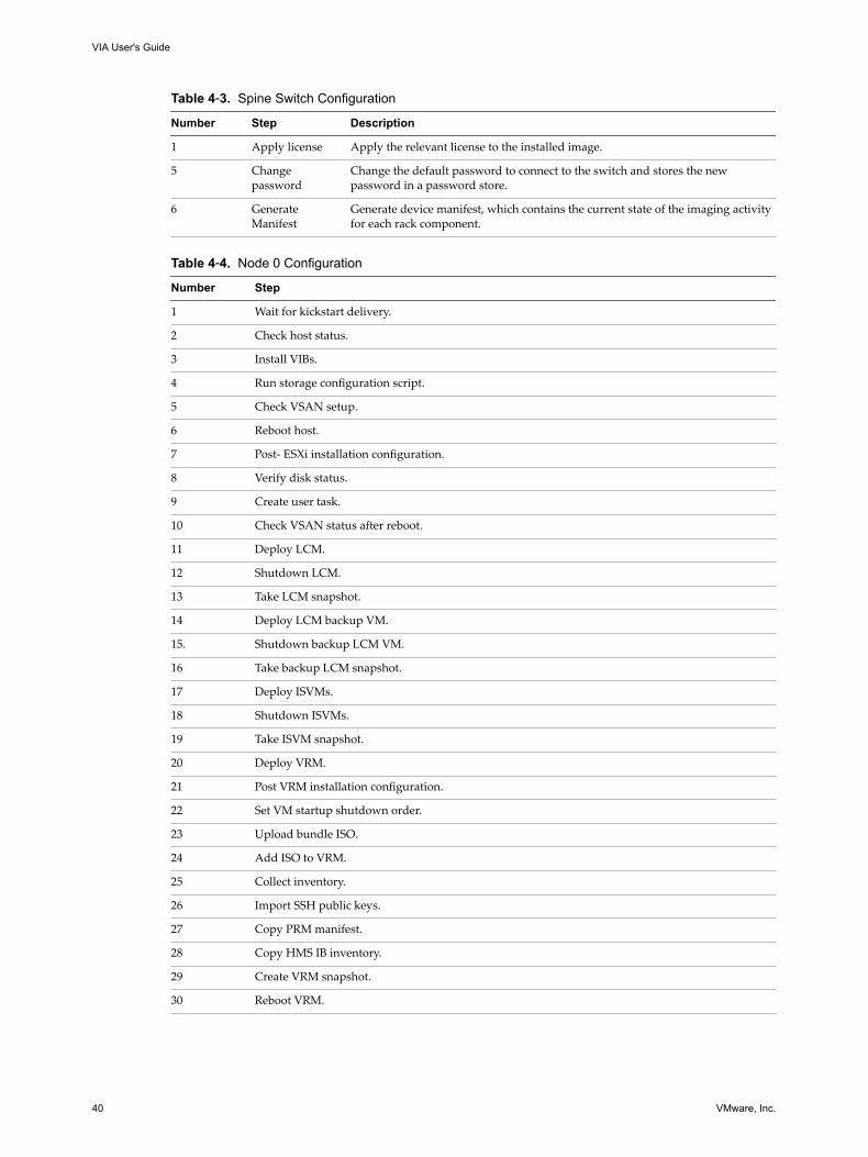
Table 4‑3. Spine Switch Configuration
Number Step Description
1 Apply license Apply the relevant license to the installed image.
5 Changepassword
Change the default password to connect to the switch and stores the newpassword in a password store.
6 GenerateManifest
Generate device manifest, which contains the current state of the imaging activityfor each rack component.
Table 4‑4. Node 0 Configuration
Number Step
1 Wait for kickstart delivery.
2 Check host status.
3 Install VIBs.
4 Run storage configuration script.
5 Check VSAN setup.
6 Reboot host.
7 Post- ESXi installation configuration.
8 Verify disk status.
9 Create user task.
10 Check VSAN status after reboot.
11 Deploy LCM.
12 Shutdown LCM.
13 Take LCM snapshot.
14 Deploy LCM backup VM.
15. Shutdown backup LCM VM.
16 Take backup LCM snapshot.
17 Deploy ISVMs.
18 Shutdown ISVMs.
19 Take ISVM snapshot.
20 Deploy VRM.
21 Post VRM installation configuration.
22 Set VM startup shutdown order.
23 Upload bundle ISO.
24 Add ISO to VRM.
25 Collect inventory.
26 Import SSH public keys.
27 Copy PRM manifest.
28 Copy HMS IB inventory.
29 Create VRM snapshot.
30 Reboot VRM.
VIA User's Guide
40 VMware, Inc.
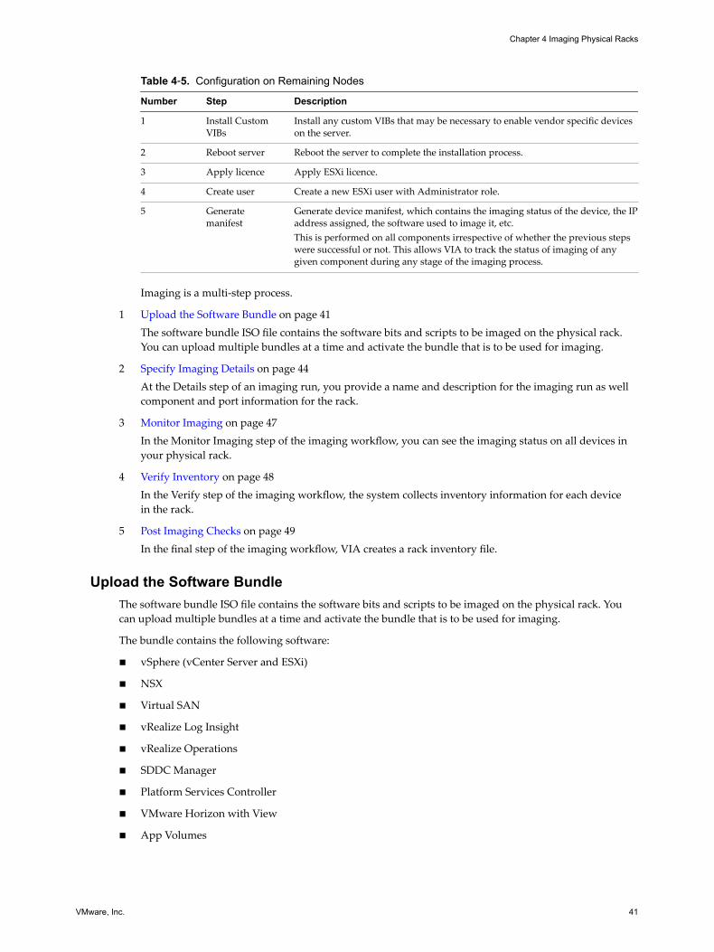
Table 4‑5. Configuration on Remaining Nodes
Number Step Description
1 Install CustomVIBs
Install any custom VIBs that may be necessary to enable vendor specific deviceson the server.
2 Reboot server Reboot the server to complete the installation process.
3 Apply licence Apply ESXi licence.
4 Create user Create a new ESXi user with Administrator role.
5 Generatemanifest
Generate device manifest, which contains the imaging status of the device, the IPaddress assigned, the software used to image it, etc.This is performed on all components irrespective of whether the previous stepswere successful or not. This allows VIA to track the status of imaging of anygiven component during any stage of the imaging process.
Imaging is a multi-step process.
1 Upload the Software Bundle on page 41The software bundle ISO file contains the software bits and scripts to be imaged on the physical rack.You can upload multiple bundles at a time and activate the bundle that is to be used for imaging.
2 Specify Imaging Details on page 44At the Details step of an imaging run, you provide a name and description for the imaging run as wellcomponent and port information for the rack.
3 Monitor Imaging on page 47In the Monitor Imaging step of the imaging workflow, you can see the imaging status on all devices inyour physical rack.
4 Verify Inventory on page 48In the Verify step of the imaging workflow, the system collects inventory information for each devicein the rack.
5 Post Imaging Checks on page 49In the final step of the imaging workflow, VIA creates a rack inventory file.
Upload the Software BundleThe software bundle ISO file contains the software bits and scripts to be imaged on the physical rack. Youcan upload multiple bundles at a time and activate the bundle that is to be used for imaging.
The bundle contains the following software:
n vSphere (vCenter Server and ESXi)
n NSX
n Virtual SAN
n vRealize Log Insight
n vRealize Operations
n SDDC Manager
n Platform Services Controller
n VMware Horizon with View
n App Volumes
Chapter 4 Imaging Physical Racks
VMware, Inc. 41
Prerequisites
n Download the Cloud Foundation software bundle and the md5sum file on your laptop, desktop, orjump VM.
n If you are re-purposing hosts in your datacenter, backup the data on the hosts. They are wiped cleanduring imaging.
n Ensure that the KVM console is closed.
n For Dell servers only, install the Dell RACADM utility on VIA.
a Download the Dell OpenManage Linux Remote Access Utilities package from http://www.dell.com/support/home/us/en/04/Drivers/DriversDetails?driverId=X9WN2.
b Unzip the tarball.
tar -xzf filename
c Navigate to the RPM location.
cd linux/rac/SLES11/x86_64/
d Install the package.
rpm -Uhv *.rpm
The RACADM utility sets most of the BIOS parameters for Dell servers automatically except for DHCPand IPMI.
n For Dell servers only, set the following BIOS parameters.
n Enable DHCP on the iDRAC/BMC port.
n Enable IPMI over LAN on BMC.
For servers from other vendors, all BIOS settings need to be set manually. See Chapter 8, “BIOSSettings,” on page 63.
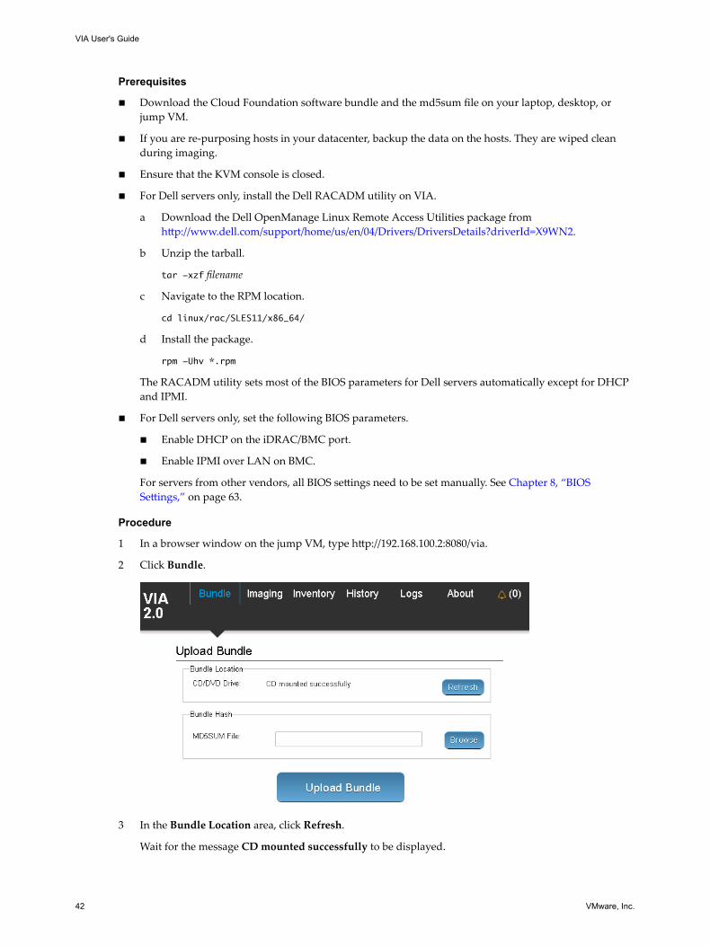
Procedure
1 In a browser window on the jump VM, type http://192.168.100.2:8080/via.
2 Click Bundle.
3 In the Bundle Location area, click Refresh.
Wait for the message CD mounted successfully to be displayed.
VIA User's Guide
42 VMware, Inc.
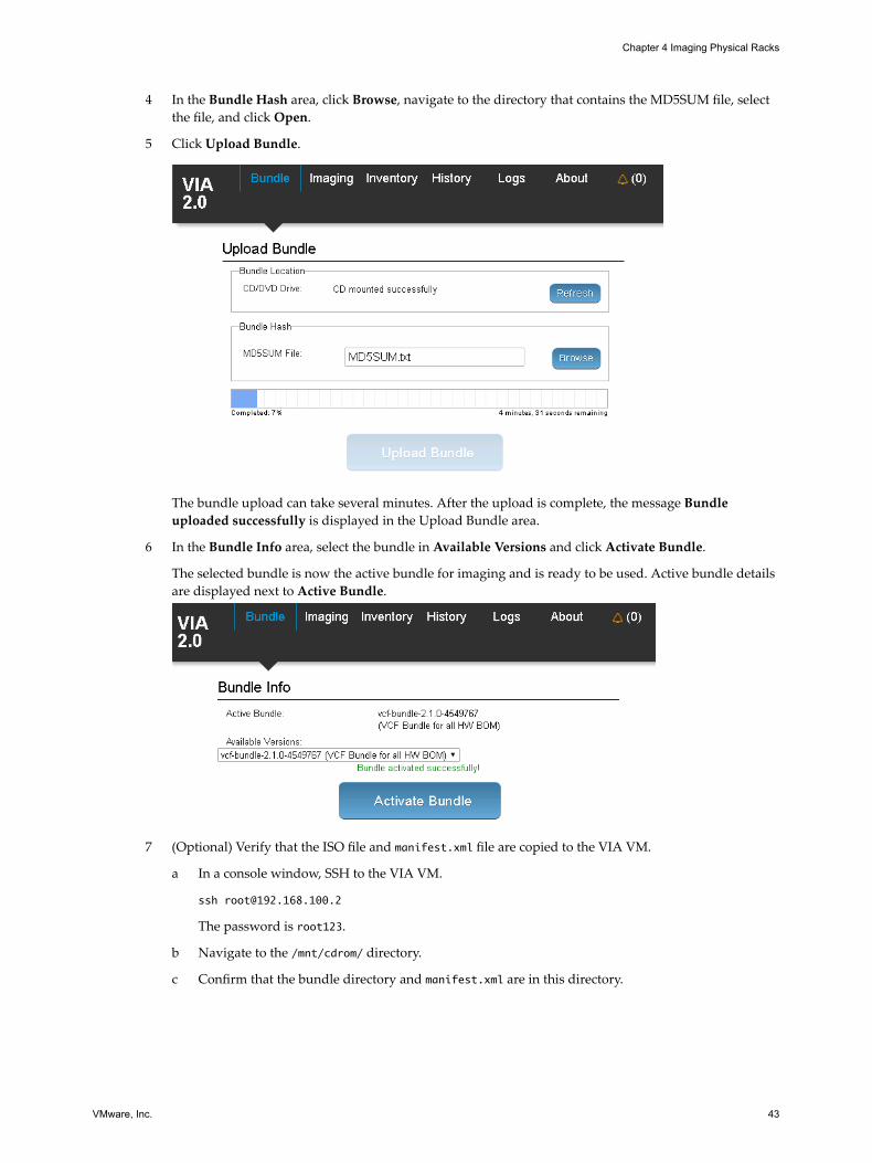
4 In the Bundle Hash area, click Browse, navigate to the directory that contains the MD5SUM file, selectthe file, and click Open.
5 Click Upload Bundle.
The bundle upload can take several minutes. After the upload is complete, the message Bundleuploaded successfully is displayed in the Upload Bundle area.
6 In the Bundle Info area, select the bundle in Available Versions and click Activate Bundle.
The selected bundle is now the active bundle for imaging and is ready to be used. Active bundle detailsare displayed next to Active Bundle.
7 (Optional) Verify that the ISO file and manifest.xml file are copied to the VIA VM.
a In a console window, SSH to the VIA VM.
The password is root123.
b Navigate to the /mnt/cdrom/ directory.
c Confirm that the bundle directory and manifest.xml are in this directory.
Chapter 4 Imaging Physical Racks
VMware, Inc. 43
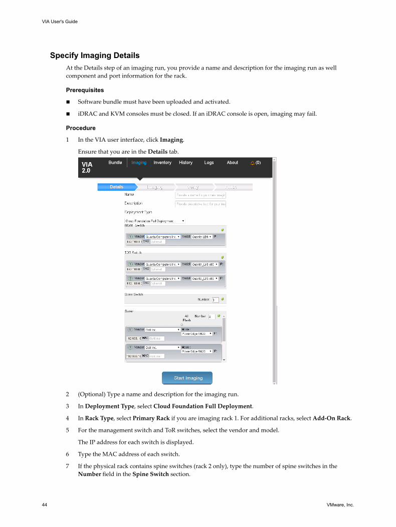
Specify Imaging DetailsAt the Details step of an imaging run, you provide a name and description for the imaging run as wellcomponent and port information for the rack.
Prerequisites
n Software bundle must have been uploaded and activated.
n iDRAC and KVM consoles must be closed. If an iDRAC console is open, imaging may fail.
Procedure
1 In the VIA user interface, click Imaging.
Ensure that you are in the Details tab.
2 (Optional) Type a name and description for the imaging run.
3 In Deployment Type, select Cloud Foundation Full Deployment.
4 In Rack Type, select Primary Rack if you are imaging rack 1. For additional racks, select Add-On Rack.
5 For the management switch and ToR switches, select the vendor and model.
The IP address for each switch is displayed.
6 Type the MAC address of each switch.
7 If the physical rack contains spine switches (rack 2 only), type the number of spine switches in theNumber field in the Spine Switch section.
VIA User's Guide
44 VMware, Inc.
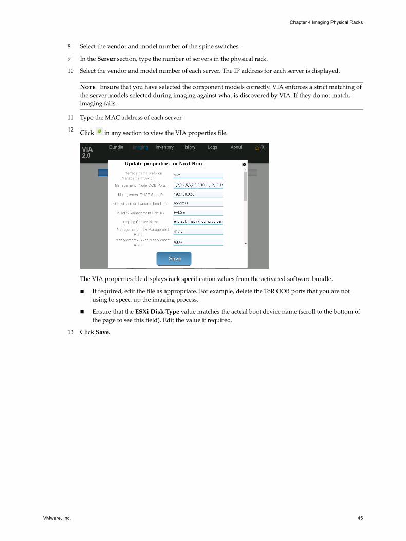
8 Select the vendor and model number of the spine switches.
9 In the Server section, type the number of servers in the physical rack.
10 Select the vendor and model number of each server. The IP address for each server is displayed.
Note Ensure that you have selected the component models correctly. VIA enforces a strict matching ofthe server models selected during imaging against what is discovered by VIA. If they do not match,imaging fails.
11 Type the MAC address of each server.
12 Click in any section to view the VIA properties file.
The VIA properties file displays rack specification values from the activated software bundle.
n If required, edit the file as appropriate. For example, delete the ToR OOB ports that you are notusing to speed up the imaging process.
n Ensure that the ESXi Disk-Type value matches the actual boot device name (scroll to the bottom ofthe page to see this field). Edit the value if required.
13 Click Save.
Chapter 4 Imaging Physical Racks
VMware, Inc. 45
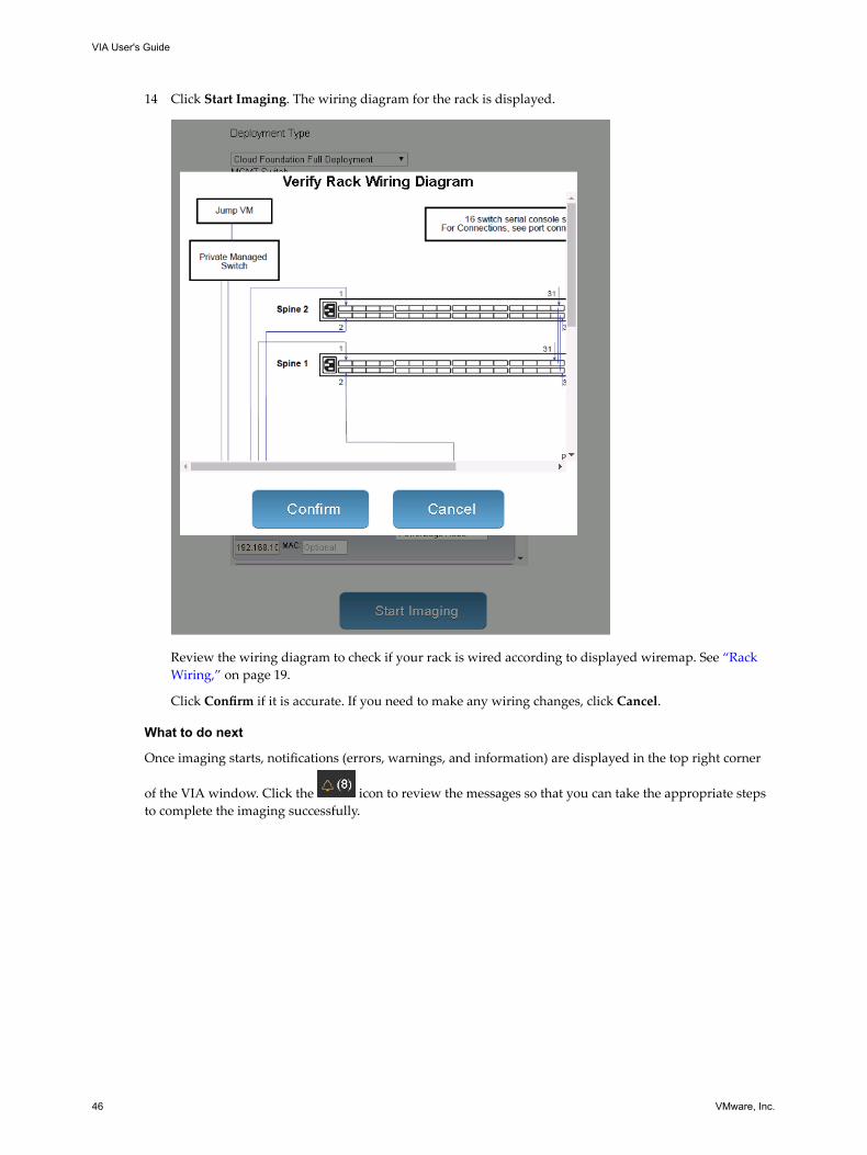
14 Click Start Imaging. The wiring diagram for the rack is displayed.
Review the wiring diagram to check if your rack is wired according to displayed wiremap. See “RackWiring,” on page 19.
Click Confirm if it is accurate. If you need to make any wiring changes, click Cancel.
What to do next
Once imaging starts, notifications (errors, warnings, and information) are displayed in the top right corner
of the VIA window. Click the icon to review the messages so that you can take the appropriate stepsto complete the imaging successfully.
VIA User's Guide
46 VMware, Inc.
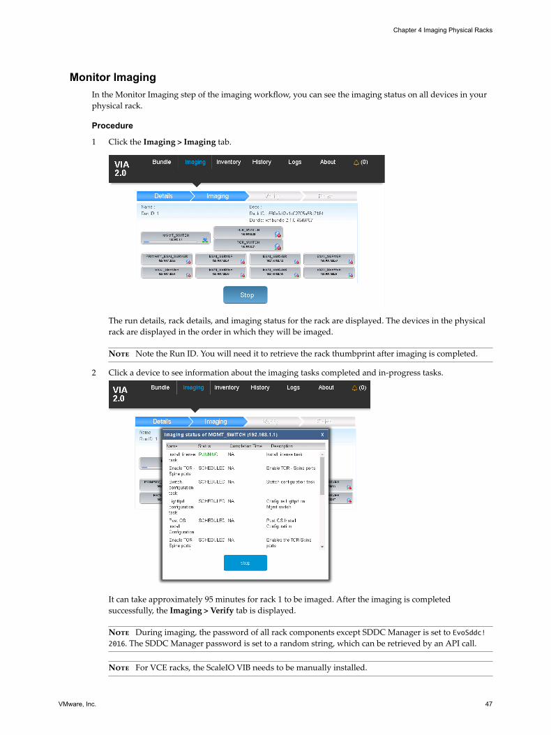
Monitor ImagingIn the Monitor Imaging step of the imaging workflow, you can see the imaging status on all devices in yourphysical rack.
Procedure
1 Click the Imaging > Imaging tab.
The run details, rack details, and imaging status for the rack are displayed. The devices in the physicalrack are displayed in the order in which they will be imaged.
Note Note the Run ID. You will need it to retrieve the rack thumbprint after imaging is completed.
2 Click a device to see information about the imaging tasks completed and in-progress tasks.
It can take approximately 95 minutes for rack 1 to be imaged. After the imaging is completedsuccessfully, the Imaging > Verify tab is displayed.
Note During imaging, the password of all rack components except SDDC Manager is set to EvoSddc!2016. The SDDC Manager password is set to a random string, which can be retrieved by an API call.
Note For VCE racks, the ScaleIO VIB needs to be manually installed.
Chapter 4 Imaging Physical Racks
VMware, Inc. 47
For information on next steps if a device fails to be imaged, see “Resume Imaging,” on page 50.
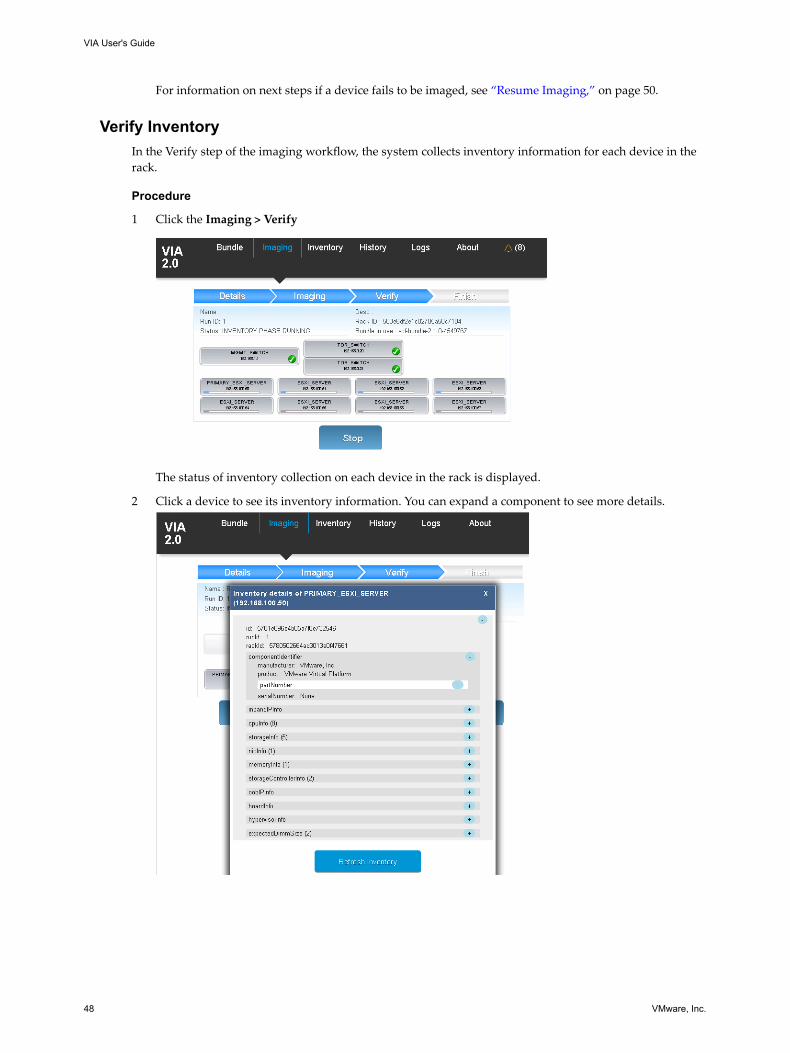
Verify InventoryIn the Verify step of the imaging workflow, the system collects inventory information for each device in therack.
Procedure
1 Click the Imaging > Verify
The status of inventory collection on each device in the rack is displayed.
2 Click a device to see its inventory information. You can expand a component to see more details.
VIA User's Guide
48 VMware, Inc.
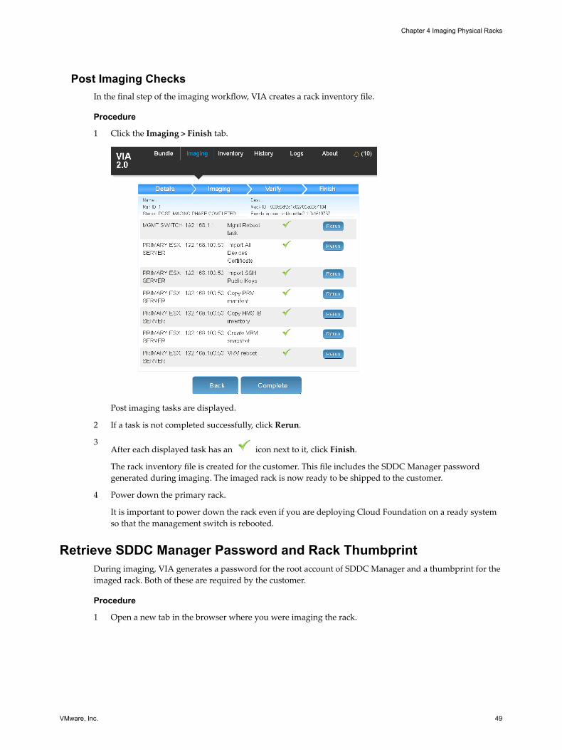
Post Imaging ChecksIn the final step of the imaging workflow, VIA creates a rack inventory file.
Procedure
1 Click the Imaging > Finish tab.
Post imaging tasks are displayed.
2 If a task is not completed successfully, click Rerun.
3After each displayed task has an icon next to it, click Finish.
The rack inventory file is created for the customer. This file includes the SDDC Manager passwordgenerated during imaging. The imaged rack is now ready to be shipped to the customer.
4 Power down the primary rack.
It is important to power down the rack even if you are deploying Cloud Foundation on a ready systemso that the management switch is rebooted.
Retrieve SDDC Manager Password and Rack ThumbprintDuring imaging, VIA generates a password for the root account of SDDC Manager and a thumbprint for theimaged rack. Both of these are required by the customer.
Procedure
1 Open a new tab in the browser where you were imaging the rack.
Chapter 4 Imaging Physical Racks
VMware, Inc. 49
2 Type the following:
192.168.100.2:8080/via/ipsecThumbprint/runId
The browser displays the SDDC Manager password, bootstrap password, and rack thumbprint.
3 Print the output.
If you are a partner imaging the rack for a customer, send this print out to the customer along with theimaged rack.
If you are imaging your own rack, keep this print out. You will need this password during bring-up.
Resume ImagingA device may fail to be imaged because of possible hardware faults or mis-configuration, or network issues.You can take a number of actions that can help in continuing with the imaging run.
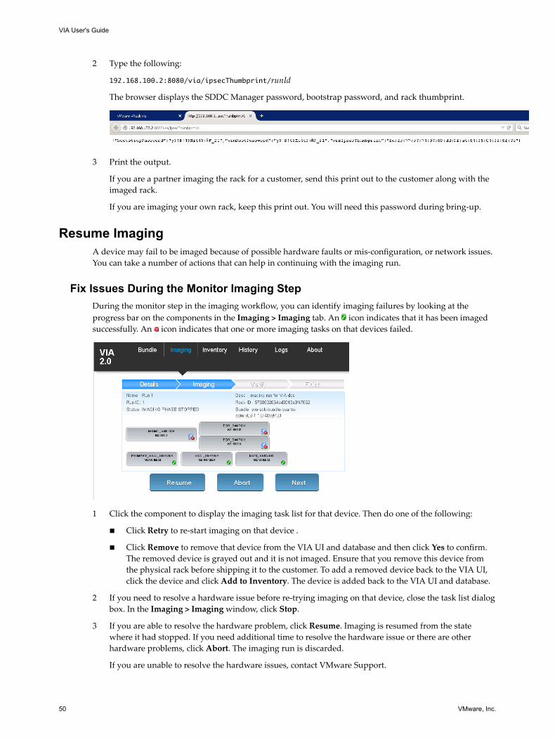
Fix Issues During the Monitor Imaging StepDuring the monitor step in the imaging workflow, you can identify imaging failures by looking at theprogress bar on the components in the Imaging > Imaging tab. An icon indicates that it has been imagedsuccessfully. An icon indicates that one or more imaging tasks on that devices failed.
1 Click the component to display the imaging task list for that device. Then do one of the following:
n Click Retry to re-start imaging on that device .
n Click Remove to remove that device from the VIA UI and database and then click Yes to confirm.The removed device is grayed out and it is not imaged. Ensure that you remove this device fromthe physical rack before shipping it to the customer. To add a removed device back to the VIA UI,click the device and click Add to Inventory. The device is added back to the VIA UI and database.
2 If you need to resolve a hardware issue before re-trying imaging on that device, close the task list dialogbox. In the Imaging > Imaging window, click Stop.
3 If you are able to resolve the hardware problem, click Resume. Imaging is resumed from the statewhere it had stopped. If you need additional time to resolve the hardware issue or there are otherhardware problems, click Abort. The imaging run is discarded.
If you are unable to resolve the hardware issues, contact VMware Support.
VIA User's Guide
50 VMware, Inc.
4 Click Next to proceed to the next step in the workflow.
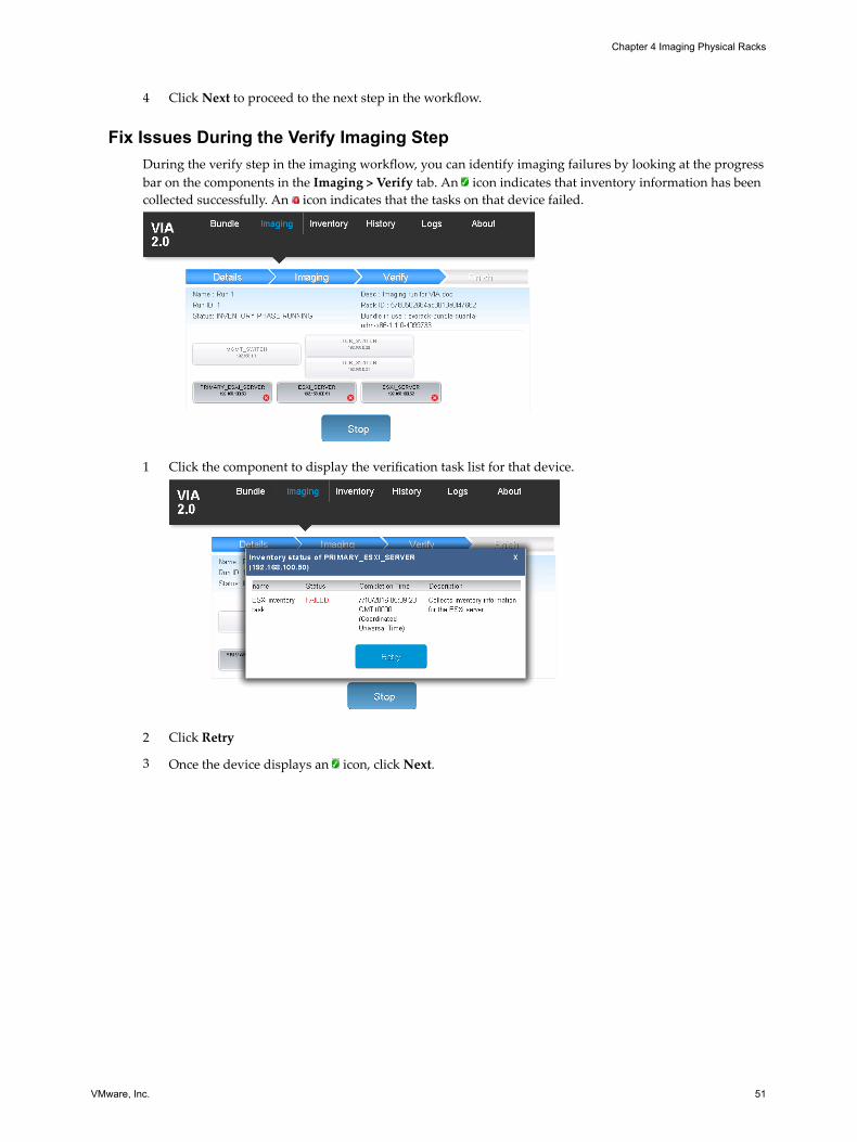
Fix Issues During the Verify Imaging StepDuring the verify step in the imaging workflow, you can identify imaging failures by looking at the progressbar on the components in the Imaging > Verify tab. An icon indicates that inventory information has beencollected successfully. An icon indicates that the tasks on that device failed.
1 Click the component to display the verification task list for that device.
2 Click Retry
3 Once the device displays an icon, click Next.
Chapter 4 Imaging Physical Racks
VMware, Inc. 51
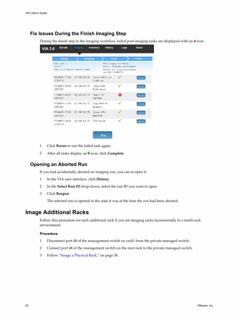
Fix Issues During the Finish Imaging StepDuring the finish step in the imaging workflow, failed post-imaging tasks are displayed with an icon.
1 Click Rerun to run the failed task again.
2 After all tasks display an icon, click Complete.
Opening an Aborted RunIf you had accidentally aborted an imaging run, you can re-open it.
1 In the VIA user interface, click History.
2 In the Select Run ID drop-down, select the run ID you want to open.
3 Click Reopen.
The selected run is opened in the state it was at the time the run had been aborted.
Image Additional RacksFollow this procedure for each additional rack if you are imaging racks incrementally in a multi-rackenvironment.
Procedure
1 Disconnect port 48 of the management switch on rack1 from the private managed switch.
2 Connect port 48 of the management switch on the next rack to the private managed switch.
3 Follow “Image a Physical Rack,” on page 38.
VIA User's Guide
52 VMware, Inc.
Imaging Individual Devices 5You can image a server or management switch as an individual device.
This chapter includes the following topics:
n “Image Individual Server,” on page 53
n “Image New Management Switch,” on page 54
Image Individual ServerYou can use the individual server imaging feature in the following scenarios:
n Imaging fails on a server in a rack
You can image that server as an individual device rather than re-imaging the complete rack.
n You are adding a new host to a Cloud Foundation rack or replacing a dead host.
You can image the new or replacement host with this feature.
Prerequisites
If this is a new or replacement host, do the following.
n Mount the host in the appropriate slot in the physical rack. For a replacement host, mount it in the sameslot as the previous host and wire it according to the same wiring connections.
n Depending on whether VIA is installed on a laptop or management host, the NIC port on the laptopmust be connected to port 48 of the management switch. Or the management host must be connected toa private managed switch that is connected to port 48 of the management switch.
n VIA must have access to ESXi OOB network (192.168.0.x) and inband network (192.168.100.x).
n Software bundle must have been uploaded.
n BIOS settings must have been set on the server to be imaged.
n In a multi-rack scenario, disconnect the spine switches temporarily while imaging is in progress. Thisprevents hosts on the other rack from being impacted by the imaging process.
For both use cases, ensure that:
n Server is in ONIE mode.
n iDRAC consoles are closed. If an iDRAC console is open, imaging may fail.
Procedure
1 In the VIA user interface, click Imaging.
Ensure that you are in the Details tab.
VMware, Inc. 53
2 (Optional) Type a name and description for the imaging run.
3 In Deployment Type, select Cloud Foundation Individual Deployment.
4 In Device Type, select ESXi_SERVER.
5 In Rack Type, select Primary Rack if you are imaging a server in rack 1. For a server in an additionalracks, select Add-On Rack.
6 Select the vendor and model number of the server. The IP address of the server is displayed.
7 If you want the displayed IP address to be assigned only to the host being imaged, type the MACaddress of the server.
8 Click Start Imaging.
9 Power on the server.
The server is discovered and the imaging process begins.
10 Open the KVM console to the server.
11 For a Dell server, change the boot device for the next boot to Local SD.
Do not power cycle or reset the server.
12 Monitor the ESXi installation on the console.
The server is rebooted after ESXi installation is complete. Ensure that ESXi is booting from the installedcopy of ESXi and not from the network.
After the server boots from the installed copy of ESXi, VIA continues imaging the server.
13 After imaging is completed, disconnect VIA and shutdown the laptop or management host.
Image New Management SwitchImaging the new management switch with VIA installs the necessary software on the switch.
Prerequisites
n Management switch must be connected to the laptop or management host where VIA is installed.
n If VIA is installed on a laptop, the NIC port on the laptop must be connected to port 48 of themanagement switch.
n If VIA is installed on a management host, the management host must be connected to a privatemanaged switch that is connected to port 48 of the management switch.
n Identify the Cloud Foundation version in your environment and ensure that the appropriate bundleand md5sum file is uploaded on VIA.
Note Do not connect the management switch to any host before or during imaging.
Procedure
1 In the VIA user interface, click Imaging.
Ensure that you are in the Details tab.
2 (Optional) Type a name and description for the imaging run.
3 In Deployment Type, select Cloud Foundation Individual Deployment.
4 In Device Type, select MGMT_SWITCH.
5 Select the vendor and model number of the switch. The IP address is displayed.
VIA User's Guide
54 VMware, Inc.

6 Click Start Imaging.
Imaging fails at collect BMC-IP information task. This is expected behavior.
7 Disconnect the switch from the laptop or management host.
Chapter 5 Imaging Individual Devices
VMware, Inc. 55

VIA User's Guide
56 VMware, Inc.
Viewing the VIA Log File 6The log file displays information for all VIA services.
Procedure
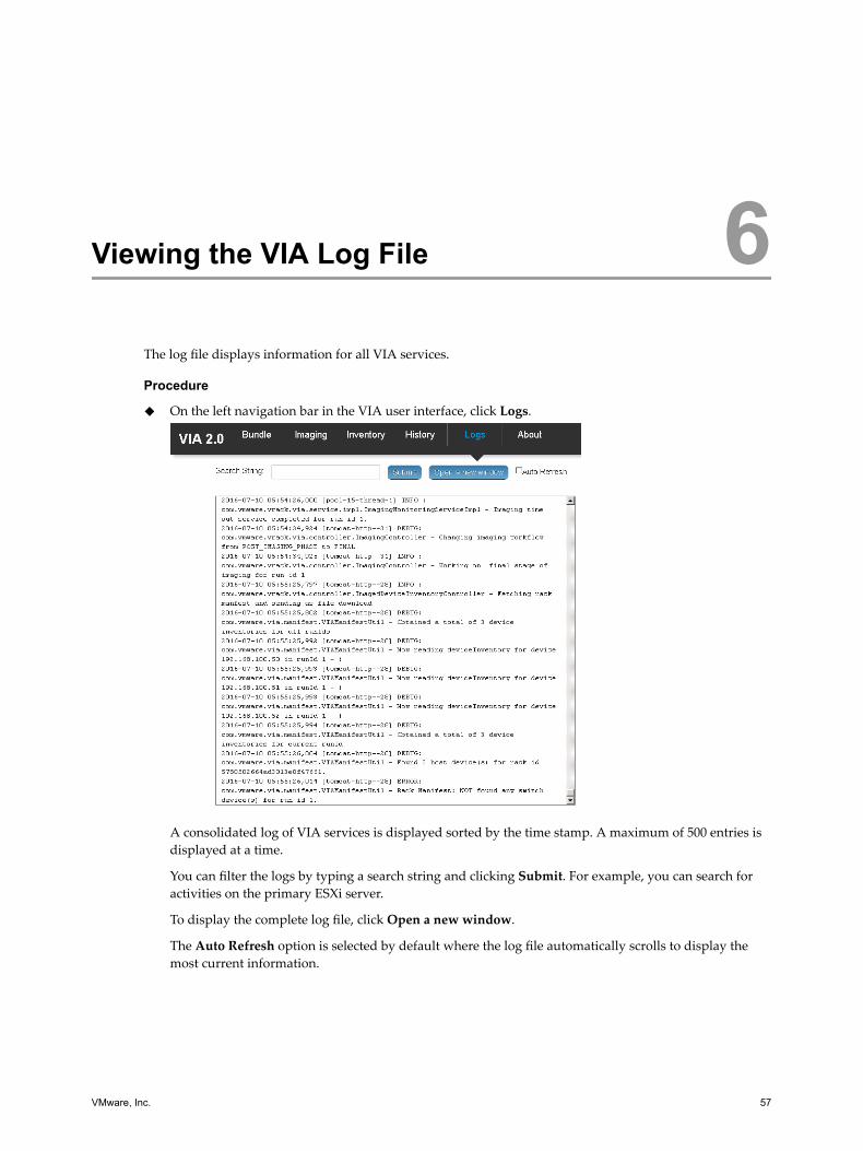
u On the left navigation bar in the VIA user interface, click Logs.
A consolidated log of VIA services is displayed sorted by the time stamp. A maximum of 500 entries isdisplayed at a time.
You can filter the logs by typing a search string and clicking Submit. For example, you can search foractivities on the primary ESXi server.
To display the complete log file, click Open a new window.
The Auto Refresh option is selected by default where the log file automatically scrolls to display themost current information.
VMware, Inc. 57

VIA User's Guide
58 VMware, Inc.
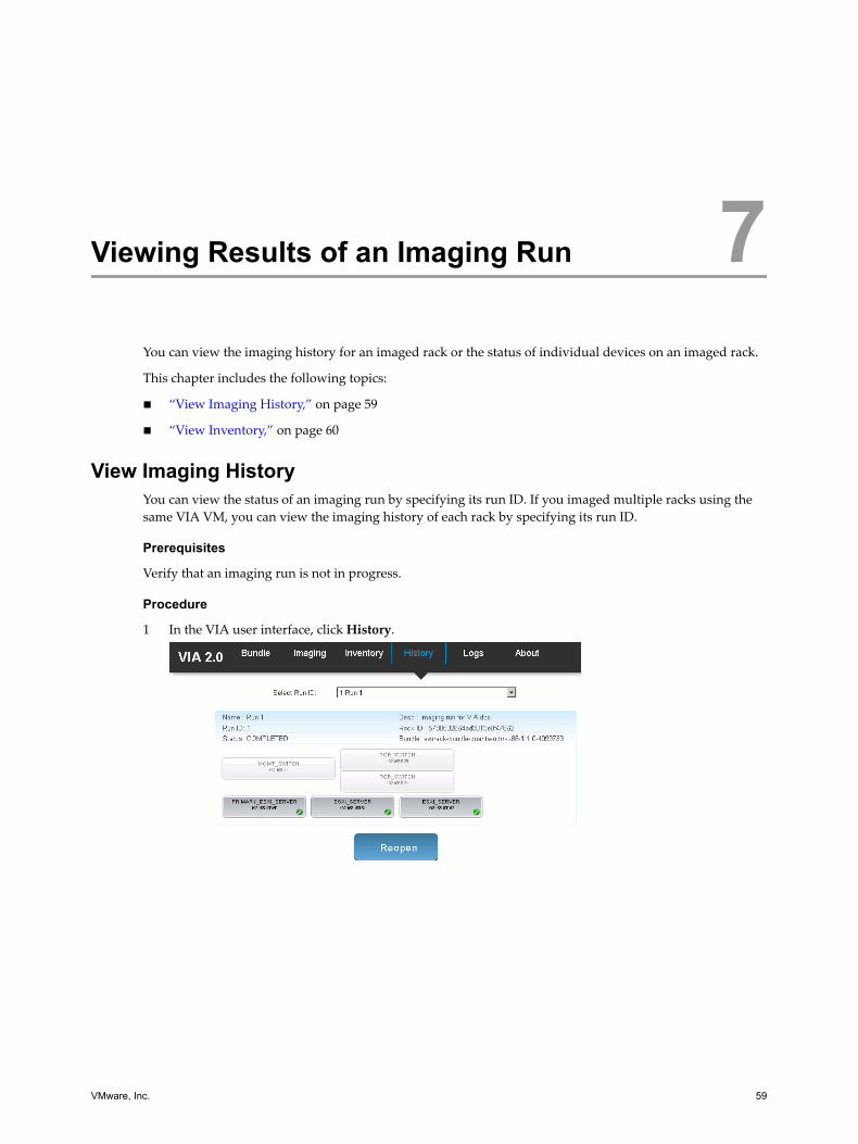
Viewing Results of an Imaging Run 7You can view the imaging history for an imaged rack or the status of individual devices on an imaged rack.
This chapter includes the following topics:
n “View Imaging History,” on page 59
n “View Inventory,” on page 60
View Imaging HistoryYou can view the status of an imaging run by specifying its run ID. If you imaged multiple racks using thesame VIA VM, you can view the imaging history of each rack by specifying its run ID.
Prerequisites
Verify that an imaging run is not in progress.
Procedure
1 In the VIA user interface, click History.
VMware, Inc. 59
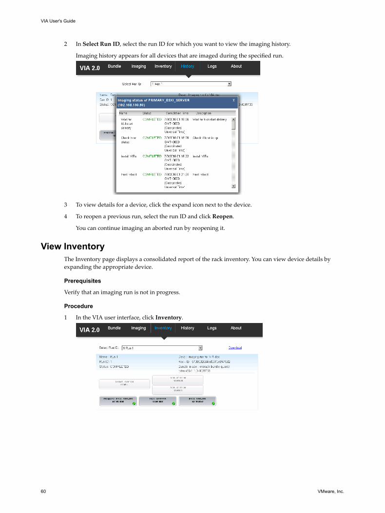
2 In Select Run ID, select the run ID for which you want to view the imaging history.
Imaging history appears for all devices that are imaged during the specified run.
3 To view details for a device, click the expand icon next to the device.
4 To reopen a previous run, select the run ID and click Reopen.
You can continue imaging an aborted run by reopening it.
View InventoryThe Inventory page displays a consolidated report of the rack inventory. You can view device details byexpanding the appropriate device.
Prerequisites
Verify that an imaging run is not in progress.
Procedure
1 In the VIA user interface, click Inventory.
VIA User's Guide
60 VMware, Inc.
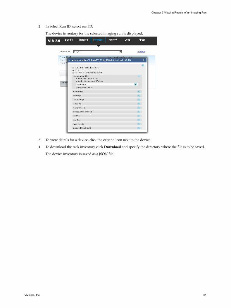
2 In Select Run ID, select run ID.
The device inventory for the selected imaging run is displayed.
3 To view details for a device, click the expand icon next to the device.
4 To download the rack inventory click Download and specify the directory where the file is to be saved.
The device inventory is saved as a JSON file.
Chapter 7 Viewing Results of an Imaging Run
VMware, Inc. 61

VIA User's Guide
62 VMware, Inc.
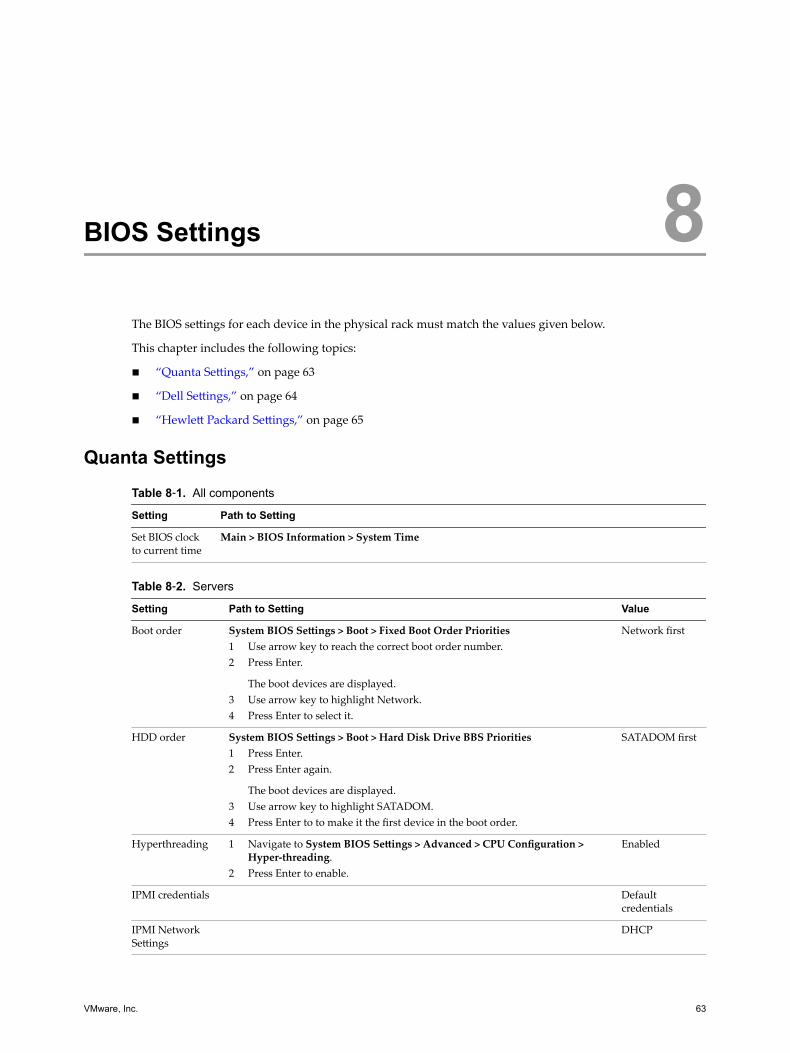
BIOS Settings 8The BIOS settings for each device in the physical rack must match the values given below.
This chapter includes the following topics:
n “Quanta Settings,” on page 63
n “Dell Settings,” on page 64
n “Hewlett Packard Settings,” on page 65
Quanta SettingsTable 8‑1. All components
Setting Path to Setting
Set BIOS clockto current time
Main > BIOS Information > System Time
Table 8‑2. Servers
Setting Path to Setting Value
Boot order System BIOS Settings > Boot > Fixed Boot Order Priorities1 Use arrow key to reach the correct boot order number.2 Press Enter.
The boot devices are displayed.3 Use arrow key to highlight Network.4 Press Enter to select it.
Network first
HDD order System BIOS Settings > Boot > Hard Disk Drive BBS Priorities1 Press Enter.2 Press Enter again.
The boot devices are displayed.3 Use arrow key to highlight SATADOM.4 Press Enter to to make it the first device in the boot order.
SATADOM first
Hyperthreading 1 Navigate to System BIOS Settings > Advanced > CPU Configuration >Hyper-threading.
2 Press Enter to enable.
Enabled
IPMI credentials Defaultcredentials
IPMI NetworkSettings
DHCP
VMware, Inc. 63
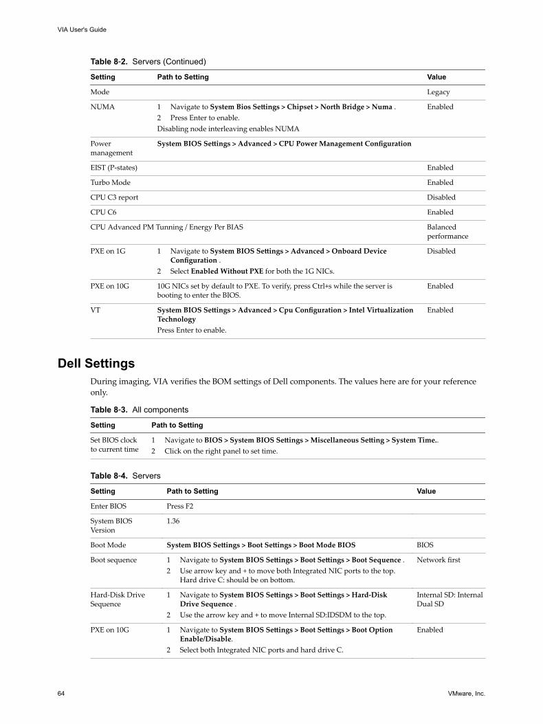
Table 8‑2. Servers (Continued)
Setting Path to Setting Value
Mode Legacy
NUMA 1 Navigate to System Bios Settings > Chipset > North Bridge > Numa .2 Press Enter to enable.Disabling node interleaving enables NUMA
Enabled
Powermanagement
System BIOS Settings > Advanced > CPU Power Management Configuration
EIST (P-states) Enabled
Turbo Mode Enabled
CPU C3 report Disabled
CPU C6 Enabled
CPU Advanced PM Tunning / Energy Per BIAS Balancedperformance
PXE on 1G 1 Navigate to System BIOS Settings > Advanced > Onboard DeviceConfiguration .
2 Select Enabled Without PXE for both the 1G NICs.
Disabled
PXE on 10G 10G NICs set by default to PXE. To verify, press Ctrl+s while the server isbooting to enter the BIOS.
Enabled
VT System BIOS Settings > Advanced > Cpu Configuration > Intel VirtualizationTechnologyPress Enter to enable.
Enabled
Dell SettingsDuring imaging, VIA verifies the BOM settings of Dell components. The values here are for your referenceonly.
Table 8‑3. All components
Setting Path to Setting
Set BIOS clockto current time
1 Navigate to BIOS > System BIOS Settings > Miscellaneous Setting > System Time..2 Click on the right panel to set time.
Table 8‑4. Servers
Setting Path to Setting Value
Enter BIOS Press F2
System BIOSVersion
1.36
Boot Mode System BIOS Settings > Boot Settings > Boot Mode BIOS BIOS
Boot sequence 1 Navigate to System BIOS Settings > Boot Settings > Boot Sequence .2 Use arrow key and + to move both Integrated NIC ports to the top.
Hard drive C: should be on bottom.
Network first
Hard-Disk DriveSequence
1 Navigate to System BIOS Settings > Boot Settings > Hard-DiskDrive Sequence .
2 Use the arrow key and + to move Internal SD:IDSDM to the top.
Internal SD: InternalDual SD
PXE on 10G 1 Navigate to System BIOS Settings > Boot Settings > Boot OptionEnable/Disable.
2 Select both Integrated NIC ports and hard drive C.
Enabled
VIA User's Guide
64 VMware, Inc.
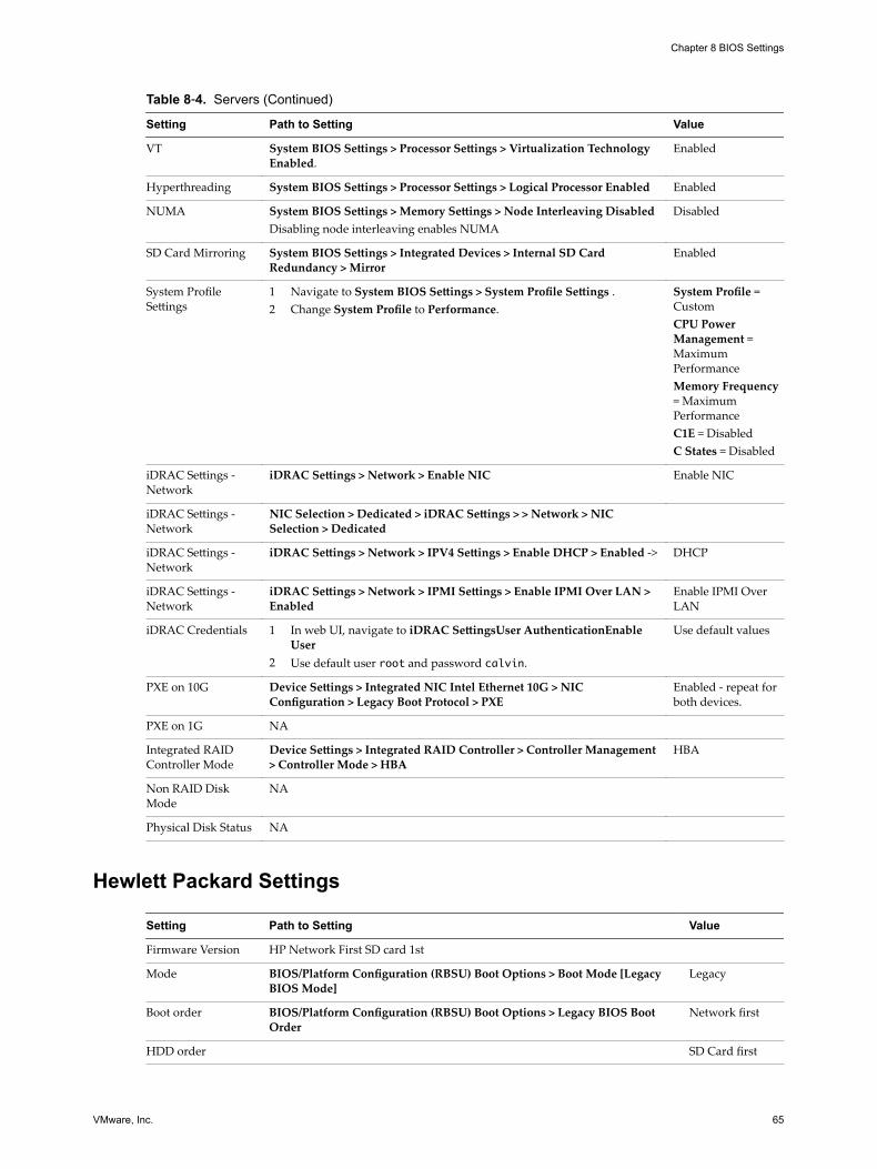
Table 8‑4. Servers (Continued)
Setting Path to Setting Value
VT System BIOS Settings > Processor Settings > Virtualization TechnologyEnabled.
Enabled
Hyperthreading System BIOS Settings > Processor Settings > Logical Processor Enabled Enabled
NUMA System BIOS Settings > Memory Settings > Node Interleaving DisabledDisabling node interleaving enables NUMA
Disabled
SD Card Mirroring System BIOS Settings > Integrated Devices > Internal SD CardRedundancy > Mirror
Enabled
System ProfileSettings
1 Navigate to System BIOS Settings > System Profile Settings .2 Change System Profile to Performance.
System Profile =CustomCPU PowerManagement =MaximumPerformanceMemory Frequency= MaximumPerformanceC1E = DisabledC States = Disabled
iDRAC Settings -Network
iDRAC Settings > Network > Enable NIC Enable NIC
iDRAC Settings -Network
NIC Selection > Dedicated > iDRAC Settings > > Network > NICSelection > Dedicated
iDRAC Settings -Network
iDRAC Settings > Network > IPV4 Settings > Enable DHCP > Enabled -> DHCP
iDRAC Settings -Network
iDRAC Settings > Network > IPMI Settings > Enable IPMI Over LAN >Enabled
Enable IPMI OverLAN
iDRAC Credentials 1 In web UI, navigate to iDRAC SettingsUser AuthenticationEnableUser
2 Use default user root and password calvin.
Use default values
PXE on 10G Device Settings > Integrated NIC Intel Ethernet 10G > NICConfiguration > Legacy Boot Protocol > PXE
Enabled - repeat forboth devices.
PXE on 1G NA
Integrated RAIDController Mode
Device Settings > Integrated RAID Controller > Controller Management> Controller Mode > HBA
HBA
Non RAID DiskMode
NA
Physical Disk Status NA
Hewlett Packard Settings
Setting Path to Setting Value
Firmware Version HP Network First SD card 1st
Mode BIOS/Platform Configuration (RBSU) Boot Options > Boot Mode [LegacyBIOS Mode]
Legacy
Boot order BIOS/Platform Configuration (RBSU) Boot Options > Legacy BIOS BootOrder
Network first
HDD order SD Card first
Chapter 8 BIOS Settings
VMware, Inc. 65
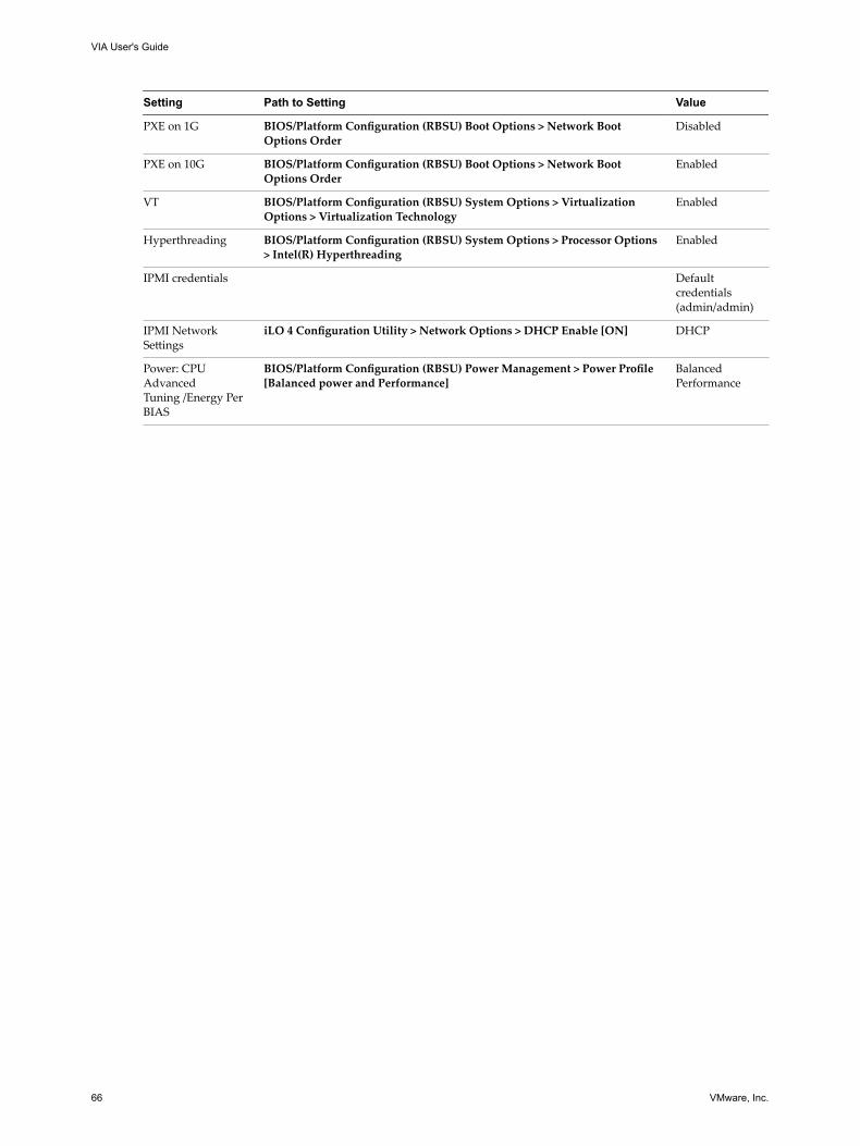
Setting Path to Setting Value
PXE on 1G BIOS/Platform Configuration (RBSU) Boot Options > Network BootOptions Order
Disabled
PXE on 10G BIOS/Platform Configuration (RBSU) Boot Options > Network BootOptions Order
Enabled
VT BIOS/Platform Configuration (RBSU) System Options > VirtualizationOptions > Virtualization Technology
Enabled
Hyperthreading BIOS/Platform Configuration (RBSU) System Options > Processor Options> Intel(R) Hyperthreading
Enabled
IPMI credentials Defaultcredentials(admin/admin)
IPMI NetworkSettings
iLO 4 Configuration Utility > Network Options > DHCP Enable [ON] DHCP
Power: CPUAdvancedTuning /Energy PerBIAS
BIOS/Platform Configuration (RBSU) Power Management > Power Profile[Balanced power and Performance]
BalancedPerformance
VIA User's Guide
66 VMware, Inc.
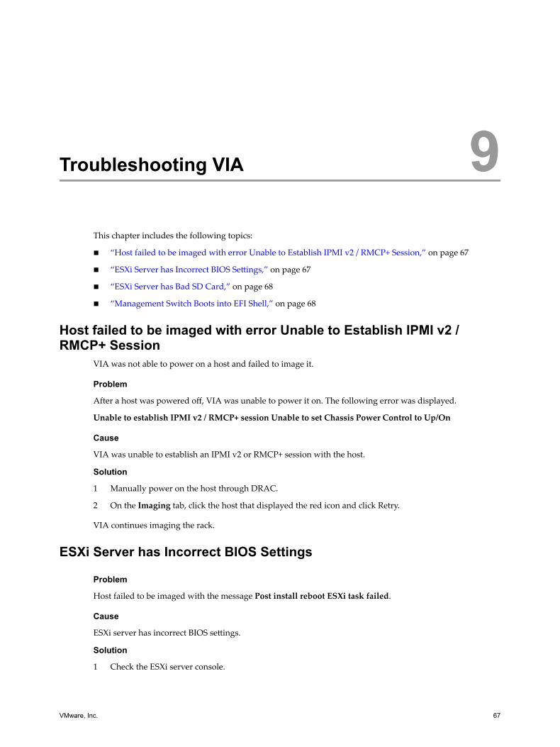
Troubleshooting VIA 9This chapter includes the following topics:
n “Host failed to be imaged with error Unable to Establish IPMI v2 / RMCP+ Session,” on page 67
n “ESXi Server has Incorrect BIOS Settings,” on page 67
n “ESXi Server has Bad SD Card,” on page 68
n “Management Switch Boots into EFI Shell,” on page 68
Host failed to be imaged with error Unable to Establish IPMI v2 /RMCP+ Session
VIA was not able to power on a host and failed to image it.
Problem
After a host was powered off, VIA was unable to power it on. The following error was displayed.
Unable to establish IPMI v2 / RMCP+ session Unable to set Chassis Power Control to Up/On
Cause
VIA was unable to establish an IPMI v2 or RMCP+ session with the host.
Solution
1 Manually power on the host through DRAC.
2 On the Imaging tab, click the host that displayed the red icon and click Retry.
VIA continues imaging the rack.
ESXi Server has Incorrect BIOS Settings
Problem
Host failed to be imaged with the message Post install reboot ESXi task failed.
Cause
ESXi server has incorrect BIOS settings.
Solution
1 Check the ESXi server console.
VMware, Inc. 67
2 If the console displays a gray screen with the message Unable to find boot device, check that the BIOSsetting is SATADOM for Quanta servers and SD card for Dell servers.
3 Fix the hardware problem.
4 On the Imaging tab, click the host that displayed the red icon and click Retry.
ESXi Server has Bad SD Card
Problem
Device failed to be imaged with the message Kickstart image not delivered..
Cause
ESXi server has bad SD card.
Solution
1 Replace the SD flash card in the ESXi server.
2 On the Imaging tab, click the host that displayed the red icon and click Retry.
Management Switch Boots into EFI Shell
Problem
After rebooting, the management switch boots into EFI shell instead of ONIE mode.
Cause
The switch was not in ONIE mode and after rebooting, it boots into an EFI shell.
Solution
1 Connect to the management swtich with a console cable.
2 Press DEL to change the boot order.
3 Select P0.
4 Select Save changes.
5 Select Save changes and restart.
6 To wipe the switch login as cumulus, type sudo cl-image-select -k.
VIA User's Guide
68 VMware, Inc.
Index
Aabout the Virtual Imaging Appliance User's
Guide 5about VIA 7
BBIOS settings
Dell 64Hewlett Packard 65Quanta 63
Cchecklist, pre-imaging 31
Ddeployment options 8
Iimage, rack 44image rack
about 38additional racks 52bundle 41post imaging checks 49
image individual devicemanagement switch 54server 53
imaged device information 60imaging 59, 60infrastructure requirements 15install VIA
on laptop or desktop 33on management host 34
installing VIA, prepare for 15
Llog file, UI 57
Pphysical rack
components 11port connectivity 23
Ssetting up environment
management host 27network cables 16
network switches 26physical servers 25rack power 16rack wiring 19virtual machines 29
Tthumbprint 49troubleshooting
host has bad SD card 68server has incorrect BIOS settings 67VIA cannot power on host 67
VVIA 15VIA database 10VIA services 10VIA inventory 10VIA software bundle 9view 59, 60
VMware, Inc. 69

VIA User's Guide
70 VMware, Inc.