viadrus hercules u28 manual for boiler operation and ... · pdf filemanual for boiler...
TRANSCRIPT

VIADRUS HERCULES U28
Manual for boiler operation and installation
GB_2015_21GB_2016_48

2
Table of contents page
1 Technical information ............................................................................................................................................ 3
1.1 Usage ............................................................................................................................................................. 3
1.2 Boiler advantages ........................................................................................................................................... 3
1.3 Boiler technical data ....................................................................................................................................... 4
1.4 Basic boiler dimensions .................................................................................................................................. 5
2 Assembly manual .................................................................................................................................................. 7
2.1 Boiler construction .......................................................................................................................................... 7
2.2 Rules and directives ....................................................................................................................................... 7
2.3 Positioning possibilities .................................................................................................................................. 8
2.4 Delivery and accessories ............................................................................................................................. 10
2.5 Assembly technique ..................................................................................................................................... 12
2.5.1 Installation of the boiler body ................................................................................................................ 12
2.5.2 Mounting of Covers ............................................................................................................................... 12
2.5.3 Way of Positioning of Side Grate in Boiler ............................................................................................ 16
2.5.4 Change of Opening Direction of Stocking Door .................................................................................... 18
2.5.5 Assembly tools for brush ....................................................................................................................... 18
2.5.6 Filling the heating system with water .................................................................................................... 19
2.6 Boiler commissioning ................................................................................................................................... 19
2.6.1 Verification activities before commissioning ......................................................................................... 19
2.6.2 Boiler commissioning ............................................................................................................................ 19
2.7 Control and safety elements ........................................................................................................................ 19
2.8 Equipment for surplus heat withdrawal ........................................................................................................ 21
2.9 Equipment for heat exhausting – accumulating reservoir ............................................................................ 23
3 Manual for operation ............................................................................................................................................ 23
3.1 Boiler operation by user ............................................................................................................................... 23
3.2 Firing ............................................................................................................................................................. 24
3.3 Operation ...................................................................................................................................................... 25
3.4 Boiler cleaning - maintenance ...................................................................................................................... 26
3.5 IMPORTANT NOTICE .................................................................................................................................. 27
4 Instruction for product disposal after its service life ............................................................................................ 28
5 Guarantee and the liability for defects ................................................................................................................. 29

3
Dear customer, we thank you that you have bought VIADRUS HERCULES U28 universal boiler, thus having shown your confidence in VIADRUS a.s. For you to get used to a correct way of handling your new product from the beginning please read at first this manual for its usage (first of all the chapter no. 3.1 – Boiler operation by user, chapter no. 3.4 – Boiler cleaning - maintenance and chapter no. 3.5 – IMPORTANT NOTICE). Please follow the stated information whereby a longlife and trouble-free boiler operation will be guaranteed for both your and our satisfaction.
1 Technical information VIADRUS HERCULES U28 is cast-iron low-pressure boiler designed for combustion of solid fuels – light coal and hard coal. As a complement fuel it is possible to use wood. Combustion of other materials, like plastics is impermissible.
1.1 Usage
The VIADRUS HERCULES U28 boiler complies with the requirements on heating up family houses, shops, schools etc. The boiler is manufactured as a hot-water boiler with both natural and forced heating water circulation and working overpressure up to 400 kPa (4 bar). Before dispatch the boiler is tested for tightness by applying 800 kPa (8 bar) testing overpressure. The boiler is designed for heating both closed and open heating systems.
1.2 Boiler advantages
1. Long lifetime of the cast-iron heat exchange and all other parts with regard to the quality of used materials.
2. Long-term verified construction.
3. Sophisticated manufacturing technology on the automatic forming lines with a constant and verified quality of the manufacturing process (ISO 9001, ISO 14 001).
4. Combustion efficiency 82 %.
5. Easy operation and maintenance.
6. Output graduation according to the sections number.
Fig. №. 1 Hydraulic loss of boiler drum
Pressure loss independence on p z – Q flow rate
Flow rate Q (10 -3 m3.s-1)
Pre
ssur
e lo
ss P
z (P
a)
Čl. = sections

4
1.3 Boiler technical data
Tab. №. 1 Dimensions, technical data Number of section s pc 4 5 6 7 Boiler class according to EN 303 - 5 - 3 Combustion chamber volume l 45,6 61,9 78,2 94,9 Water space volume l 52,6 62 71,7 81,3 Weight kg 364 437 510 583 Combustion chamber depth mm 311 422 533 644 Diameter of smoke socket mm 156 Boiler dimensions: height x width mm 1165 x 695
depth L mm 831 942 1053 1164 Filling opening dimensions mm 318 x 265 Maximum working water overpressure kPa
(bar) 400 (4)
Minimum working water overpressure kPa (bar)
50 (0,5)
Testing water overpressure kPa (bar)
800 (8)
Boiler hydraulic loss - See Fig. no. 1 Minimum output water temperature °C 60 Control range of water temperature °C 60 – 85 Noise level dB Does not exceed the level 65 dB (A) Boiler connections – heating water “ 1 1/2
– return water “ 1 1/2 Cooling water temperature for equipment for surplus heat withdaral
°C 5 – 20
Cooling water overpressure for equipment for surplus heat withdaral
kPa (bar)
200 – 600 (2 - 6)
Tab. №. 2 Technical data – hard coal as fuel
Granularity 20 – 40 mm, fuel moisture max. 15 % Calorific value of fuel: 14 – 20 MJ.kg-1
Number of sections pc 4 5 6 7 Nominal heat output kW 19 25 30 35 Fuel consumption at nominal heat output kg.h-1 3,7 4,7 5,8 6,8 Fuel efficiency MJ.kg-1 19,68 Burning time at nominal output hour 4 Flue gases temperature at nominal heat output
°C 232 – 288
Flue gases mass flow rate at nominal output kg.s-1 0,0156 0,0205 0,0254 0,0303 Efficiency % 80 79 79,5 78,5 Required chimney draught mbar 0,16 0,2 0,25 0,30 Tab. №. 3 Technical parameters – hard coal as fuel
Granularity 20 – 40 mm, fuel moisture max. 15 % Calorific value of fuel: 26 - 29 MJ.kg-1
Number of sections pc 4 5 6 7 Nominal heat output kW 20 27 35 44 Fuel consumption at nominal heat output kg.h-1 3,15 4,2 5,4 6,5 Fuel efficiency MJ.kg-1 24,2 Burning time at nominal output hour 4 Flue gases temperature at nominal heat output
°C 243 – 295
Flue gases mass flow rate at nominal output kg.s-1 0,0196 0,0251 0,0306 0,0361 Efficiency % 78,4 79,5 81 82,8 Required chimney draught mbar 0,2 0,23 0,27 0,3

5
1.4 Basic boiler dimensions
4 5 6 7 L mm 492 603 714 825 L1 mm 831 942 1053 1164 D mm 156
Fig. №. 2 Basic boiler dimensions

6
1 Front cell 2 Center cell 3 Middle section without lower bar 4 Rear cell 5 Feeding gate (with the rosette of primary air) 6 Cleaning cover -upper 7 Cleaning cover - lower 8 Dump grate 9 Ash gate (with a suffocating throttle of secondary air) 10 Smoke extension piece 11 Air rosette (tertiary air) 12 Boiler case (complete) 13 Thermo-manometer
14 Draught regulator 15 Pipe of output water 16 Filling and cock 17 Pipe of input water 18 Two-way safety cock DBV 1 - 02 19 Safety valve 20 Small ash pan with a movable cover
(tertiary air) 21 Ash pan 22 Partition of the smoke adapter 23 Partition of the flue gases area
Fig. №. 3 Basic boiler parts

7
2 Assembly manual 2.1 Boiler construction
The main boiler part is the cast-iron sectional boiler drum made of the grey cast-iron according to EN 1561, quality 150. The pressure parts meet the strenght demands according to EN 303- 5. The boiler drum is assembled of sections by means of pressed boiler nipples with 56 mm diameter and secured by anchor bolts. The boiler sections create the feed space, combustion and ash space, water space and convectional space. The heating water input and output is situated at the rear boiler part. There is placed the smoke adapter and heating water connection at the upper part of rear boiler section and the return water connection at the bottom part. The water connection is possible to connect by means of thread pipes. The stoking door, ash door and 2 cleaning covers are connected to the front boiler section. Under the ash pan door there is installed the tilting grate. The whole boiler drum is insulated by the health harmless mineral insulation, which reduces the losses caused by heat transmission into the environment. The boiler sell is coloured by a good quality comaxit spray.
2.2 Rules and directives
The solid fuel boiler can be installed by the company holding a valid certification for its installation and maintenance. There must be made lay-out according to the valid rules for the boiler installation. Before the boiler installation to the older heating system the installation company must make the flush (cleaning) of the whole heating system. The heating system must be filled with water meetin g the requirements ČSN 07 7401, especially its hardness must not exceed the require d parameters.
Tab. №. 4 Recommended values
hardness mmol/l 1 Ca2+ mmol/l 0,3 Concentration of whole Fe + Mn mg/l (0,3)*
*) recommended value
WARNING!!! The use of anti-freeze mixture is not re commended by the manufacturer.
In case of two way safety vent reaction, when there is a possibility of boiler having been filled with the water, which does not meet the ČSN 077401 requirements it is necessary to change th e water in the heating system so that it meets the ČSN 077401 requirements again.
a) to the heating system ČSN 06 0310 Heating systems in buildings – Designing and installation ČSN 06 0830 Heating systems in buildings – protecting device ČSN 07 7401 Water and steam for thermal energy equipments with working pressure up to 8 MPa. EN 303-5 Boilers for central heating – Part 5: Solid fuel boilers for central heating with manual or
automatic feed and max. 500 kW nominal thermal output: terminology, requirements, testing and marking.
b) to the chimney ČSN 73 4201 Chimneys and flue gas ducting– designing, implementation and connection of fuel
consumers.
c) regarding the fire regulations ČSN 06 1008 Fire safety of heat installations. EN 13501-1 +A1 Fire classification of construction products and building elements – Part 1: Classification
using test data from reaction to fire tests
d) to the system of HWS heating ČSN 06 0320 Heating systems in buildings – Hot water preparation – Designing and planning ČSN 06 0830 Heating systems in buildings – Safety devices. ČSN 75 5409 Water installations inside buildings.

8
2.3 Positioning possibilities
Boiler positioning in the living space (including c orridors) is prohibited! The installation of the boiler must comply with all requirements of ČSN 06 1008.
Permanent access of air must be ensured in the room where the boiler will be installed and operated.
Boiler positioning with regard to the fire regulations: 1. The boiler can be installed on a fire-proof floor (Fig. no. 4):
− Place the boiler on fire-proof base exceeding the boiler platform by 20 mm on sides and only up to the boiler drum depth.
− If the boiler is positioned in a cellar, we recommend installing it on a retaining wall minimum 50 mm hight. − Install the boiler in the middle of the retaining wall.
Quantity of sections 4 5 6 7 L [mm] 494 605 716 827
Fig. №. 4 Boiler base dimensions 2. A safe distance from the combustible materials:
− when installing and operating the boiler it is necessary to keep a safety distance of 200 mm from the materials of combustibility grade A1, A2, B and C (D);
− for easily combustible materials of combustibility grade E (F), which quickly burn and burn themselves even after removal of ignition source (such as paper, cardboard, asphalt and tar paper, wood and wood-fiber boards, plastics, floor coverings) the safe distance has to be doubled, i.e. to 400 mm;
− safe distance should be doubled as bulb where the grade of reaction to fire has not been proved. Tab. №. 5 Grade of reaction to fire
Grade of reaction to fire Examples of building materials and pro ducts included in the reaction to fire (Extract from EN 13501-1 + A1)
A1 – incombustible Granite, sandstone, concrete, bricks, ceramic tiles, mortars, fireproof plasters, … A2 – combustible with difficulty acumin, izumin, heraklit, lignos, boards and basalt felt, fibreglass boards,... B – hardly combustible Beech and oak wood, hobrex boards, plywood, werzalit, umakart, sirkolit,... C (D) – medium combustible Pinewood, larch, whitewood, chipboard and cork boards, rubber flooring,...
E (F) – easily combustible Asphaltboard, fibreboards, cellulose materials, polyurethane, polystyrene, polyethylene, PVC,…

9
Boiler positioning with regard to the necessary handling space:
• Basic environment AA5/AB5 according to ČSN 33 2000-1 ed. 2. • In front of the boiler there must be left a minimum handling area of 1000 mm. • The minimum distance between the rear part of boiler and the wall 400 mm. • At least from one side part keep the access area to the back boiler part of minimum 400 mm. • Minimal distance from the wall at the left side of boiler is 100 mm. In a case of modification with left opening of
the door, the distance from the wall must be bigger because of door opening in sufficient action range.
Fig. №. 5 Modifications of stocking door opening Fuel positioning:
• It is interdicted to store the fuel behind the boiler or next to the boiler within a distance smaller than 400 mm. • It is interdicted to store the fuel between two boilers in the boiler-room. • The producer recommends to keep the distance between the boiler and fuel min. 1000 mm or to store the fuel
in a different room that where the boiler is installed. The selection of the right boiler size The selection of the right boiler size, it means the heating output, is very important condition for economic operation and the right boiler function. The boiler must be selected so that the heating output conforms to the heating loss of the object. The nominal output of the boiler is counted according to the valid rules for outside temperature –12 °C, -15 °C and –18 °C. The boiler selection with too high heating output (overrating) results in tarring and ratting of boiler. It is not useful to use the boiler with higher output than the heating loss of the boject. Chimney draught The chimney with the right chimney draught is the fundamental prerequisite for the right boiler function. It influences the boiler output as well as its efficiency. The boiler can be connected to the venting unit with the sufficient chimney draught, see. Chapter no. 1.3. and if the revision by the certified organization is made.
Fig. №. 6 Positioning of Boilers in Boiler Room

10
2.4 Delivery and accessories
The boiler is packed in a transport package and must not be tilted over during the transport. The accessories are put inside the boiler drum, accessible by opening the stoking door. Standard Boiler Delivery:
• Boiler with appropriate number of sections on a pallete • Cover with insulation including an ash pan, a bracket of cleaning tools – type 2, cover of a movable and small
ash pan of the appropriate size • Heating and return water tubes G 1 1/2" 2 pcs • Side grate -4 sections 4 sections - 1 pc, 6 sections - 1 pc • Side grate -5 sections 5 sections - 1 pc, 7 sections - 1 pc • Side grate -additional 6 sections - 1 pc, 7 sections - 1 pc • Cleaning tools - handle 1 pc • A packet • A production label • Commercial and technical documents
Packet Accessories:
• Door hinges 2 pcs • A handle 503a - 514 1 pc • A magnetic element - flat 1 pc • Brush 1 pc • Stabbler 1 pc • Jointing material for covers:
- Butterfly nut M4 1 pc - Nut M5 1 pc - Nut M6 2 pc - Nut M8 1 pc - Washers 4,3 9 pcs - Washers 5,3 4 pcs - Washers 6,4 2 pcs - Large-area washers 6,4 2 pcs - Washers 8,4 2 pcs - Connecting pins 8 pcs - Screws M4 x 6 9 pcs - Screws M5 x10 6 pcs - Screws M6 x 35 2 pcs - Screws M8 x 12 1 pcs - Screws ST 4,8 x 13 11 pcs - Spring leave retainers 8 pcs
• A pull rod of smoke control 1 pc • Jointing material for the pull rod of smoke control:
- Cotter pins 2,5 x 20 2 pcs - A nut M10 1 pc - Washers 10,5 2 pcs - A plastic ball M10 1 pc
• A thermomanometer 1 pc • A screw of suffocating throttle 1 pc • A special hook 1 pc • A socket spanner with a handle, hexagonal 902-13 1 pc • Filling and discharging cock Js 1/2“ 1 pc • Draught regulator - complete 1 pc • Plug Js 1 1/2“- blind 1 pc • Under plug sealing 1 pc • Stick-on label – position of a partition of smoke extension 1 pc • Screws M5x10 2 pc • Nust M10 5 pc • Washers 10,5 6 pc • Washers 5,3 2 pc

11
Necessary accessories: (they are not included in delivery):
• Two-ways safety valve DBV 1 – 02 (1 pc) incl. siesal (10 g); this equipment has not to be used in case of open heating system
• Safety valve – 1 pc By request (is not included in delivery):
• Filter 3/4“ – for delivery with the two way safety vent DBV 1 - 02 Necessary accessories for combustion of additional fuel - timber (It is not a part of delivery):
4 sections 5 sections 6 sections 7 sections • Additional adapter - timber 1 2 2 3 • Small additional adapter - timber 1 1 • Additional grate 4 sections 2 2 • Additional grate 5 sections 2 2 • Additional grate- additive 2 2 • Ceramics of combustion chamber 4 sections 1 1 1 • Ceramics of combustion chamber 5 sections 1 • Additional ceramics of combustion chamber
2 sections 1
• Additional ceramics of combustion chamber 3 sections
1
a) Ceramics of combustion chamber 5 sections b) Ceramics of combustion chamber 4 sections c) Additional ceramics of combustion chamber 3 sections d) Additional ceramics of combustion chamber 2 sections e) Additional grate 5 sections f) Additional grate 4 sections g) Additional grate - additive h) Additional adapter - timber j) Small additional adapter - timber
Fig. №. 7 Necessary Accessories for Combustion of Additio nal Fuel - Timber The necessary accessories and optional boiler acces sories is not included in the boiler standard price .

12
2.5 Assembly technique
2.5.1 Installation of the boiler body
1. Fit the boiler drum on the retaining wall (substruction). 2. Mount to the boiler drum system outlet the connecting tube G 1 1/2“. It must be connected by means of a
removable joint to the heating system. 3. Mount to the boiler drum system outlet the connecting tube G 1 1/2“. It must be connected by means of a
removable joint to the heating system. 4. To connect two-way safety valve DBV 1 - 02 with connecting pipe of recurrent and heating water and with the
input of cold water and with the output of excessive heat according to Fig. no.15. 5. Mount the discharging valve to 1/2“ thread in tube of heating water according to Fig. no. 3. 6. Set the smoke tube to the smoke adapter and insert it into the chimney. The diameter of smoke tube is 160
mm. 7. Screw the draught regulator into the opening in upper part of front section. The boiler draught regulator
adjustment procedure is described in the manual enclosed to the particular regulator. 8. Blind the threated opening JS 6/4“ in the front section with JS 6/4“ plug. Place the sealing under the plug.
2.5.2 Mounting of Covers
1. Take the covers out from the cardboard wrapping. 2. Fit the metal components by the appropriate connecting material according to Fig. no. 8:
− Pos. 1 Insert 2 pcs of connecting pins into left side part of the cover; − Pos. 2 Insert 2 pcs of connecting pins into right side part of the cover. Then connect it with the front part of
the cover by means of 2 pcs of door hinges and by 8 pcs of M4 x 6 screws and 8 pcs of 4,3 washers.
− Pos. 3 Fit the middle part of the cover by 4 pcs of spring leaf retainers and screw the magnetic element up by means of M5 nut;
− Pos. 4 Complete the small ash pan with removable cover (screw the removable cover and the small ash pan by means of 1 pc of 4,3 washer and 1 pc M4 butterfly nut).
− Pos. 5 Fit the upper part of the cover by 4 pcs of spring leaf retainers and screw the front curtain up by means of 3 pcs of ST 4,8 x 9,5 screws. Screw the console of drawbar up by 2 pcs of M5 x 12 screws.)
3. According to the Fig. no. 9 – cover the boiler.
4. Insert the small ash pan (11) with removable cover (21) into the boiler drum.
5. Screw up 2 pcs of cleaning cover console (8 and detail A) to the cleaning covers by means of 1 pcs of M8 x12 screws and 2 pcs of 8,4 washers.
6. Put the cover consoles (10 and detail C) on the anchoring screws and secure them by 4 pcs of M10 nuts and 4 pcs of 10,5 washers.
7. Put the side parts of the cover with insulation on the consoles and secure them by means of 4 pcs of M5x12 screws and 4 pcs of 5,3 washers (detail D). By means of 2 pcs of connecting pins, screw the left side part of the cover on the front section of the boiler drum. By means of 2 pcs M5 x 10 screws and 2 pcs of 5,3 washers, screw the right side part of the cover on the front section of the boiler drum.
8. Insert the insulation into the front part of the cover (22 + 23) and srew the handle up by means of 2 pcs of M6 x 35 screws and by 2 pcs of 6,4 large–area washers
9. Screw 2 pcs of connection pins into the front section (see detail E) and put on the middle part of the cover with insulation (4).
10. Assembling of the pull rod of smoke control according to the detail B. Parts list: - 2 pcs cotter pins - 2 pcs washers 10,5 - 1 pc nut M 10 Insert the cotter pins into the smoke extension and put the washers 10,5 on. Put the pull rod on the smoke extension partition and secure it by 10,5 washers and the cotter pins. Screw the M10 nut on the pull rod.
11. Insert the thermo-manometer into the upper part of the cover. Screw the manometer capillary tube into the return valve and insert the capillary tube of thermometer into the bulb and secure it by capillary spring.
12. Put the upper part of the cover (3) with insulation on the side parts of the cover (1 and 2). Screw the plastic ball M10 on the pull rod of smoke control.
13. Screw the upper back metal sheet by 2 pcs of ST 4,8 x 9,5 screws to the left side part of the cover.
14. Further screw the back metal sheet with insulation (6) by means of 5 pcs of ST 4,8 x 9,5 screws to the left and right part of the cover.
13
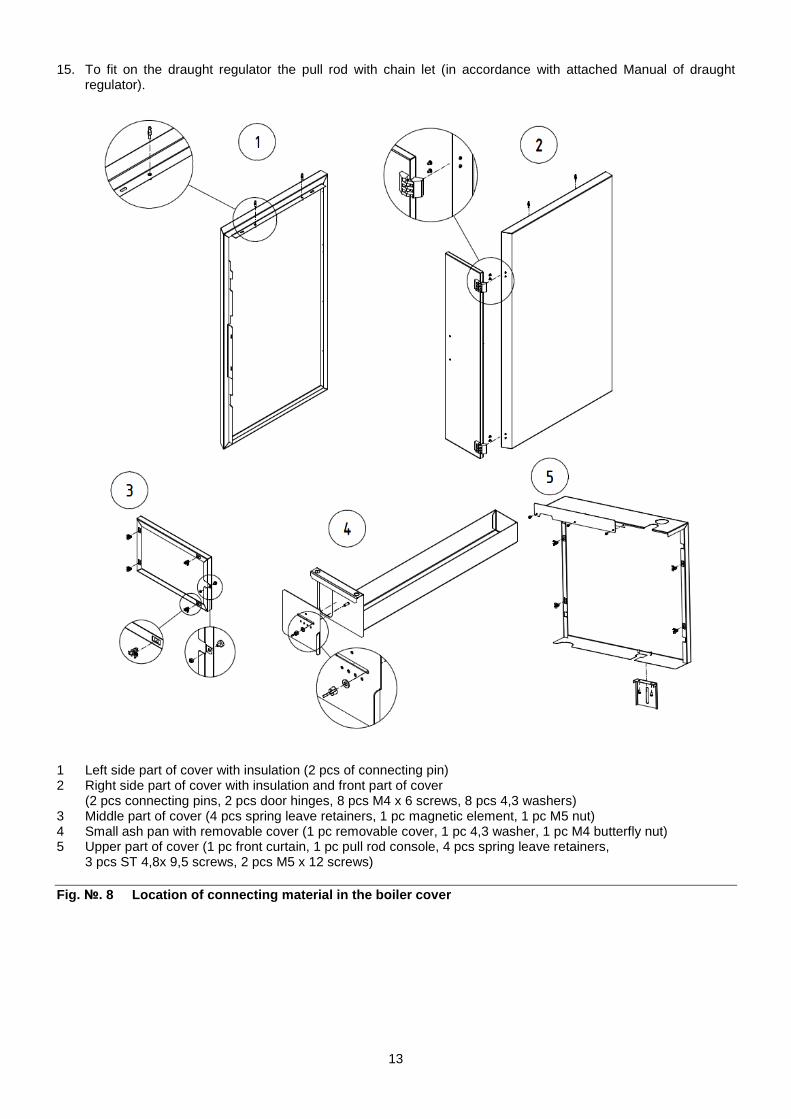
15. To fit on the draught regulator the pull rod with chain let (in accordance with attached Manual of draught regulator).
1 Left side part of cover with insulation (2 pcs of connecting pin) 2 Right side part of cover with insulation and front part of cover
(2 pcs connecting pins, 2 pcs door hinges, 8 pcs M4 x 6 screws, 8 pcs 4,3 washers) 3 Middle part of cover (4 pcs spring leave retainers, 1 pc magnetic element, 1 pc M5 nut) 4 Small ash pan with removable cover (1 pc removable cover, 1 pc 4,3 washer, 1 pc M4 butterfly nut) 5 Upper part of cover (1 pc front curtain, 1 pc pull rod console, 4 pcs spring leave retainers,
3 pcs ST 4,8x 9,5 screws, 2 pcs M5 x 12 screws)
Fig. №. 8 Location of connecting material in the boiler c over

14
1 Left side part of cover with insulation
(2 pcs connecting pins, 2 pcs M5 x 12 screws, 2 pcs 5,3 washers)
2 Right side part of cover with insulation (2 pcs connecting pins, 2 pcs M5 x 10 screws, 2 pcs 5,3 washers)
3 Upper part of cover with insulation 4 Middle part of cover with insulation
(2 pcs connecting pins) 5 Front part of cover with insulation
(4 pcs M4x6 screws, 4 pcs 4,3 washers) 6 Back part of cover with insulation
(5 pcs ST 4,8 x 9,5 screws) 7 Upper back metal sheet
(2 pcs ST 4,8 x 9,5 screws) 8 Console of cleaning cover
(1 pcs M8 x 12 screws, 2 pcs 8,4 washers)
9 Pull rod of smoke control (2 pcs cotter pins, 2 pcs 10,5 washers, 1 pc M10 nut)
10 Console of cover (4 pcs M10 nuts, 4 pcs 10,5 washers)
11 Small ash pan 12 Plastic ball M10 13 Pull rod console 14 Smoke extension 15 Cotter pin 2,5 x 20 16 Smoke extension partition 17 M10 nut 18 10,5 washer 19 Stick-on label – positon of smoke extension
partition 20 Front curtain 21 Removable cover 22 Insulation of front metal sheet 23 Insulation of upper front metal sheet

Fig. №. 9 Boiler Cover
Note: Before stoking it is necessary to open the p artition in smoke adaptor by means of the pull rod of smoke control. Thus the flue gases are discharged t hrough the shorting opening into the chimney.

16
2.5.3 Way of Positioning of Side Grate in Boiler
1 Section Grate Head Metal
Fig. №. 10 Position of Side Grate in Boiler Side grate will be positioned in the boiler under the angle of about 45 ° between 4 and 5 section grate head metal, see the detail in Fig. no. 10.

17
1 Side grate 4 sections 2 Side grate 5 sections 3 Side grate -additive
Fig. №. 11 Positions of Side Grates in Individual Sizes o f Boiler (Coal fuel) Side grates serve for combustion of coal fuel. If a ddtitive fuel of timber is combusted, take off thes e grates from the boiler.
Boiler 4 sections Boiler 5 sections
Boiler 6 sections Boiler 7 sections

18
2.5.4 Change of Opening Direction of Stocking Door
1. Raise the upper part of cover (13). 2. Disassemble the stocking door (1) by taking 2 pcs of door pins off (7). 3. Remove 2 pcs of M10 x 55 screws (4) including 2 pcs of M10 nuts (5) and 2 pcs of 10,5 washers (6) into the
head metals on the left side. 4. Disassemble the support piece for the catch (9) and screw it on by means of 2 pcs of M8 x 12 screws (8) on the
right hand side. 5. Disassemble the protective plate of the stocking door with insulation (10) by releasing of 2 pcs M8 x 16 screws
(12) and 2 pcs of 8,4 washers (11). Take out the 8 x 30 pin (3) and the catch (2) from the stocking door. Reassemble the protective plate with insulation. Remove the catch on the right side of the door and secure it by the pin.
6. Hang the stocking door on the 2 pcs of M10 x 55 screws and secure it by 2 pcs of door pins. 7. Verify tightness of the areas of contact of the door.
1. Stocking door 2. Catch 3. 8x30 Pin 4. M10x55 Screw 5. M10 Nut 6. 10,5 Washer 7. Door pin
8. M8x12 Screw 9. Supporting piece for catch 10. Protective plate of stocking door including Insulation 11. 8,4 Washer 12. M8 x 16 Screw 13. Upper part of cover
Fig. №. 12 Change of Opening Direction of Stocking Door
2.5.5 Assembly tools for brush
Use the leather gloves and common assembly tools for mounting or dismounting of the brush and the spike point (if they are included in the delivery).

19
2.5.6 Filling the heating system with water
The water hardness must correspond to ČSN 07 7401 and it is inevitable to treat the water according to Chap. no. 2.2. in case the water hardness is unsati sfactory. The heating systems with an open expansion tank allow the direct contact between the heating water and the atmosphere. During the heating season the water expanding in the tank absorbs the oxygen, which increases its corrosive effects and at the same time the water evaporates heavily. Only the water treated to the values according to ČSN 07 7401 can be used for refilling. The heating system must be thoroughly flushed out in order to wash out all impurities. During the heating season it is necessary to keep a constant volume of heating water in heating system and be particular about bleeding the heating system to avoid the air suction into the system. Water from the boilers and heating system must never be discharged or taken for usage except in cases of emergency like the repairs etc. Water discharge and filling with new water increases the danger of corrosion and scale development. In case we have to refill the heating system with water we onl y do this operation when the boiler is cold in order to prevent its sections from getting broken. After boiler and heating system refilling operation the all joints must be tested for tightness. When using the two way safety vent DBV 1 - 02 the c ooling water is added gradually to the to the rever se water. The assembly and stoking test completion must be recorded in the “Guarantee certificate”.
2.6 Boiler commissioning
This boiler can only be commissioned by a professio nal assembly firm authorized to do this activity.
2.6.1 Verification activities before commissioning
Before the boiler put into operation it is necessary to check: a) filling the heating system with water (thermomanometer check) and the system tightness; b) connection to the chimney – this connection can only be done with the agreement of a chimney firm
(chimney revision); c) closing of smoke adapter partition (impurities associated with the installation of the boiler chimney system); d) draught regulator and two-way safety valve DBV 1 - 02.
2.6.2 Boiler commissioning
1. Fire a boiler 2. Bring the boiler to the necessary operating temperature. The recommended output water temperature is 80 C. 3. Adjust the draught regulator including the chain length (according to the enclosed draught regulator manual). 4. Operate the boiler in the operating condition according to the relevant standards. 5. Check again the boiler tightness. 6. Acquaint the user with the operation and maintenance. 7. Make a record in the Guarantee certificate.
2.7 Control and safety elements
Stocking door rosette serves for primary air supply into the combustion chamber. The rosette setting has been described further in Table no. 6. Tab. №. 6 Setting of Stocking Door Rosette for Primary Ai r Supply (mm) 4 5 6 7 Black coal 3 - 4 3 - 4 4 - 6 6 - 8 Brown coal 3 - 4 3 - 4 4 - 6 6 - 8

20
Fig. №. 13 Stocking Door Rosette for Primary Air Supply The rosette in the boiler back part stays closed. If smoke comes out the chimney, the rosette may be opened a little bit. By that more tertiary air is admitted into the boiler. The suffocating throttle of ash pan door controls inlet of secondary combustion air under the boiler grate. It is controlled by a damper or manually by the adjusting screw of the suffocating throttle. The removable cover on the small ash pan serves for inlet of tertiary air (see Fig. no. 3 - Pos. 20). Tab. №. 7 Adjustment of Removable Cover Position towards Small Ash Pan for Inlet of Tertiary Air
(Position) 4 5 6 7 Black coal 2 3 5 O Brown coal 2 3 5 O The position is informative only. In a case of smoke coming out the chimney (the same as in the case of stocking door rosette), it is possible to open the removable cover more to prevent from respective smoking.
U Closed O Opened
Fig. №. 14 Position of Removable Cover towards Small Ash pan for Inlet of Tertiary Air The combination appliance – thermo-manometer – is used for the heating water temperature and the water stress in the heating system detection. The pit of the thermo-manometer sensor is located in the upper part of the front boiler cell.

21
2.8 Equipment for surplus heat withdrawal
The two way safety vent DBV 1 - 02 serves for surpl us heat removal in case the water temperature in bo iler exceeds 95 °C. In case the system is equipped with a two way safety vent and the boiler becomes overheated (the output temperature exceeds 95 °C) the two way safety vent creates a cold water circuit which is kept until the temperature drops below the limit temperature. At this moment there are simultaneously closed the discharge cooling equipment and the cold water inlet of refilling the system.
The two way safety vent DBV 1 – 02 technical data ( from the firm Regulus)
Opening temperature (limit): 100 °C (+0° - 5 °C) Maximum temperature: 120 °C Maximum stress on boiler side 400 kPa (4 bar) Maximum stress on water side 600 kPa (6 bar) Nominal flow at �p 100 kPa (1 bar): 1,9 m3/h Usage
The two way safety vent DBV 1 – 02 is used as a protection of heating boilers against overheating. In the valve body there is the bleed and supply valve controlled by thermostatic element. When the limit temperature is reached, the bleed and supply valve is simultaneously opened meaning that the cold water is running in and the hot water is running out. When the temperature drops below limit, the bleed and supply valve is simultaneously closed.
Caution! It is not a compensation for safety valve.
In case of two way safety vent reaction, when there is a possibility of boiler having been filled with the water, which does not meet the ČSN 077401 requirements it is necessary to change th e water in the heating system so that it meets the ČSN 077401 requirements again.
Fig. №. 15 The two way safety vent DBV 1 - 02
It is necessary to install a safety valve for maxim um overpressure of 400 kPa (4 bar) on the system an d its dimension must correspond to the rated boiler outpu t. The safety valve must be located directly behind the boiler. Any stop valve must not be located between the safety valve and boiler. If you have any questi ons, please contact our contractual assembly firm and se rvice organizations.
Installation
Installation can be only carried out by a qualified person. For the correct operation of the thermostatic, two ways safety vent it is necessary to comply with the conditions for its installation and keep the flow directions marking on its body. The safety vent is always mounted in the output pipe of boiler or directly on the upper part of boiler, where the hot water leaves boiler and is transported into heating system. When installing the vent it is necessary to check, if the 3/4“ socket usage, which can be both in pipeline and on boiler, ensures complete immersion of the thermostatic vent element after the vent installation. After the vent has been installed in socket, connect the down pipe, in which the hot water from boiler will flow to drain, to „C“(see. fig. no. 15). The cooling water inlet, which will cool the boiler after setting the vent in operation, is connected (see fig. no. 16) to „A“ (see fig. no. 15). The filter for mechanical impurities must be installed in the cooling water inlet. It is necessary to connect the pipeline to „B“ (see. fig. no. 15) and the pipeline is to be led into reverse flow pipe of heating system near the boiler (see fig. no. 16).
A – cold water inlet B – output to boiler C – output to drain D – input from boiler

22
1 – Boiler 2 – Two way safety vent DBV 1 – 02 3 – Safety valve 4 – Transforming valve 5 – Filter 6 – Ball-shaped cock
7 – Pump 8 – Surplus heat removal 9 – Bleed valve I – Cooling water inlet II – Heating water outlet III – Return water inlet
Fig. №. 16 The recommended scheme of the two way safety v ents DBV 1 – 02 connection
Regular maintenance
Once a year it is necessary to turn the safety vent’s head to remove possible impurities formed in the vent. Clean the cooling water inlet filter.
In case of using an open expansion tank it is not n ecessary to use a pressure protecting device agains t overheating. Every heat source in an open heat system must be connected with an open expansion tank positioned at the highest point of the heat system. The expansion tanks must be rated in the way that they can contain the changes in water volume resulting from heating and cooling. The open expansion tanks must be equipped with non-closable bleeder and an overflow pipes. The overflow pipe must be designed in the way that it safely drains off the maximum flow volume entering the system. This can be achieved by rating the overflow pipes by one DN higher than that of the filling piping. The expansion tanks and their connecting pipes must be designed and positioned in the way that freezing is reliably inhibited.
Fig. №. 17 The examples of open expansion tanks connectio n
1 Heat source 2 Expansion tank 3 Safety piping 4 Expansion piping 5 Overflow piping 6 Filling piping 7 Water level limiter 8 Reverse piping

23
2.9 Equipment for heat exhausting – accumulating re servoir
The boiler has to be operated with an accumulating reservoir.
Calculation of the smallest capacity of the accumulating heat exchanger,
Vsp = 15Tb x QN (1-0,3 x (QH/Qmin)) where: Vsp accumulating reservoir capacity in liters QN nominal heat power in kW Tb combustion time in hours QH buildings’ heat load in kW Qmin smallest heat power in kW
The sizes of the accumulating reservoir have to be determined on the basis of the boiler power and the used fuel. The biggest capacity has to taken into consideration, whereas the minimum used capacity of the reservoir has to be 300 l.
In case that the reservoir is fully charged, it is necessary to shut down the boiler and heat up by heat from the accumulating reservoir. After the heat is spent in the reservoir, put the boiler into operation again. The accumulating reservoir enables provision of heat comfort and at the same time the boiler operation.
ATTENTION! Failure of it will cause extreme polluti on of the boiler drum.
Hydraulic schemes of the boilers with an accumulating reservoir are at disposal in the project materials of Viadrus at www.viadrus.cz.
3 Manual for operation 3.1 Boiler operation by user
Incorrect operation and improper combustion of fuel leads to damage to the product.
During the first ignition of the cold boiler, water condenses therein and then flows down its inner wa lls. This condensation of the boiler body ends when the boiler reaches operating temperature. During the operation of the boiler at the temperatu re lower than 60 °C, condensing of water on the boi ler body or the so called low temperature corrosion can take, which shortens the life of the boiler exchan ger. Therefore we recommend to operate the boiler at 60 °C and higher. SOFT COAL The most suitable fuel is sort coal with 20 – 40 mm granularity. Burning time at nominal output is 4 hours. HARD COAL The most suitable fuel is hard coal of 20 – 40 mm granularity. Burning time at nominal output is 4 hours. ADDITIONAL FUEL – WOOD Using this fuel it is not reached the nominal outpu t.
Guarantee of clean and good combustion is to use on ly dry and wood in the natural state.
It is necessary to keep the wood max. humidity 20%. If the humidity is higher than 20%, output of the boiler decreases. Combustion of the damp wood releases wat er which condenses on the walls of the boiler and chimney body, this leads to an increased formation of tar and water vapor, which reduces the life of t he heat exchanger. Furthermore, improper combustion ca uses corrosion of cast iron called "Metal dusting", which leads to carbon diffusion into the material, and thus disintegration of the material to a powder (dust). This process is gradual and long-term. Flue gas str eam with solid particles then causes abrasion or erosion of material from the surface, thereby gradu ally thinning the wall thickness of the elements, a nd this can cause perforation of the boiler body. Fuel must be stored in a dry place. For heating, do not use plastics, household waste, chemically treated wood residues, waste paper, wood chips, brushwood, garbage from boards pressed from the bark or chipboards.

24
▶ Follow the instructions for operating the boiler. ▶ When operating the boiler follow the recommended op erating temperature. ▶ Operate the boiler with an approved fuel.
I.
II.III.
III.
O
Z
Fig. №. 18
3.2 Firing
1. Check the water volume in the heating system on thermomanometer.
2. Open the closing fittings between the boiler and the heating system.
3. Clean the grate and ash-pan.
4. Check the closed position of the smoke adapter partition (Any coal, ash or carbon deposit mustn’t be left between the areas of contact).
5. Before lighting the fire and every stocking, it is necessary to open the partition of the smoke extension by means of smoke control pull rod. By that, the flue gases are discharged through a shorting hole into the chimney.
6. Insert the kindling and wood trough the ash door on the cleaned grate all over its depth.
7. Light the kindling through the ash door.
8. Close the ash door and open fully the choke.
9. Put the basic fuel bed on the burning wood.
10. After its good igniting, stock the other fuel in order that the fuel was not poured into the shorting hole. For proper function of the boiler it is necessary that the partition of the smoke adapter closes tightly (see chap. 2.6.1 item c).
11. After closing the stoking door close the partition of smoke adapter by means of the pull rod of smoke control. Thus the shorting opening is closed.
Note: In course of making fire the boiler dewing can occur – it is not considered as a defect.
I. primary air II. secondary air III. tertiary air O open–Lighting fire/Stocking Z closed - Operation

25
Fig. №. 19 Scheme of flue gas passage through the boiler
3.3 Operation
1. After having achieved the heating water temperature regulate the combustion air inlet. Power control is executed by the suffocating throttle that regulates secondary air inlet under the grate by means of the damper or by the adjusting screw of the suffocating throttle itself. Adjust the regulator so that the ash door choke is nearly closed at the moment of achieving the required heating water temperature (see a separate Operating Manual of Damper).
2. As need may be during the operation, fuel up the boiler again (hot layer suitable for further fuel stoking is min. 15 cm). Stoke in the way making sure that the fuel layer is equally high along the whole depth of the boiler.
ATTENTION! Prior opening of the stoking door it is necessary to open the smoke adapter partition with use of the smoke control pull rod.
3. According to Table no. 6, slightly open the rosette of stocking door for inlet of primary air.
4. The rosette in the back part of the boiler must stay closed. In a case of smoke coming out of the chimney, slightly open the rosette. Inlet of tertiary air in the front part of the boiler is controlled by means of a removable cover fixed to the small ash pan. This small ash pan must be completely closed and pressed to the front section in order that unrequired air was sucked.
Important notice! The dark smoke from the chimney signals not fully c losed partition of the smoke adapter or a lack of tertiary air. A large volume of tertiary air result s in cooling of flue gases and thereby reducing the efficiency of the boiler. Full closure of stoking d oor rosette can also cause dark smoke from the chimney and boiler tarring .
5. At the transition to the night top-fed stove damped operation the grate must be cleaned and freshly stoked fuel must flare. The rosette of stoking door is also kept ajar the draught controller in this case can be unhung (the choke completely closed). Close the choke of ash pan door.
6. The morning re-putting into operation make by opening the ash door choke, together with poking up the grate after the ash door opening.
7. The ash door must be closed during the boiler operation.
8. If necessary, clean the ash pan, and the small ash pan with removable cover (the gloves needed).

26
3.4 Boiler cleaning - maintenance
1. Ash from ash pan and small ash pan has to be removed in the boiler operation even several times a day according to the type of used fuel, because full ash pan protects the correct division of the combustion air under fuel and evokes rough burning of fuel on grate. Al residues in the boiler furnace, mainly cinder have to be removed before each new burning start and in course of the morning boiler operation reinsertion. It is necessary to put away the ash into the fireproof containers with covering. During working period it is necessary to use safety helps and to care the personal safety.
Fig. №. 20 Disassembling of Cleaning Cover
2. After the heating season end or as needed (this is influenced by the quality of fuel, chimney draught and setting of boiler) it is necessary to clean up the boiler flue gas passage. Unscrew the cleaning covers by means of the socket spanner with a handle, take the covers out by means of the special hook and clean up the flue gas passages by the appropriate cleaning tools (Fig. no. 20). Clean up the air channels by the hook. Discharge the small ash pan. Reassemble the cleaning covers.
3. After cleaning up the flue gas passages, yopu must clean up the smoke extension. According to Fig. no. 21 unscrew the cleaning cover of the smoke extension. Clean up the space of the smoke extension and reassemble the cleaning cover.
4. Provided settlement of tar agglomeration on the combustion space walls has been occurred in course of using fuels with greater gas formation we remove them with scraper or with burning out using hardwood under the boiler putting into maximum working temperature at the open partition of the smoke adapter.
5. After the heating season ending it is necessary to clean the interconnection between the boiler smoke adapter and chimney and then to treat pivots of the flue gas flap with the carbon grease.
1 Upper cleaning cover 2 Lower cleaning cover 3 Middle part of cover 4 M8 Nut 5 8,4 Washer 6 Socket spanner with a
handle, hexagonal 7 Special hook

27
Fig. №. 21 Cleaning of the smoke extension piece
3.5 IMPORTANT NOTICE
1. The boiler only can be used for the purpose that it is destined for.
2. The boiler can be operated only by adult persons acquainted with this operation manual. It is inadmissible to leave the children unattended by ad ults near the boiler. The boiler construction intervention, which can endanger the attendant´s sa fety, eventually the housemate´s safety, is inadmissible.
3. The boiler is not destined for the use by person s (incl. children) whose physical, sensual or menta l disability or lack of experience and knowledge prev ent them from a safe use of the appliance unless they are supervised or if they were not instructed on the use of appliance by a person responsible for their safety.
4. Children should be supervised in order to ensure that they do not play with the appliance.
5. If there occurs a danger or flammable vapours an d gases development and penetration into the boiler room, or at works accompanied by the temporary deve lopment of the fire or explosion (gluing the floor covering, painting with combustible painting colour s), the boiler must be duly closed down before the works start.
6. It is FORBIDDEN to use the flammable liquids for boiler firing.
7. It is FORBIDDEN to overheat the boiler during it s operation. Fill the boiler under the lower edge o f stoking door. Open the stoking door by use of plast ic handle and half-open the ash door to smoke vent the smoke gases.
8. It is forbidden to put the flammable materials o n the boiler or in its near distance.
9. When cleaning the ashes at boiler there must not be put any flammable materials within minimally 1500 mm distance from the boiler.
10. When operating the boiler at the temperature lo wer than 60 C the boiler drum can be bedewed, whic h means the low-temperature corrosion and reduction o f boiler drum service life. Therefore we recommend to operate the boiler at the temperature of 60 C and higher. Possible corrosion marks on boiler drum don´t mean a defect and they don´t affe ct the boiler function.
11. In case of a storage container usage, the boile r can be fired or stoked up again, if the boiler is burned down to the fire basis, and the storage container i s empty or cool.
ATTENTION! Ignoring leads to extreme heat exchange r fouling.
1 Insulation of the cleaning covering of the smoke extension part
2 Cleaning covering of the smoke extension piece
3 Washer 5,3 4 Screw with the hexagon head M5 x 14

28
12. After the heating season termination it is nece ssary to clean the boiler, smoke-flues and smoke adapter properly. Spread the graphitic grease on sw ivel taps, smoke flap mechanism and on other flexible parts of boiler. Keep the boiler room clea n and dry.
13. In case the heating system is not daily used in winter season, then the water from boiler must be drained.
14. It is necessary to install a safety valve for m aximum overpressure of 400 kPa (4 bar) on the syste m and its dimension must correspond to the rated boiler o utput. The safety valve must be located directly behind the boiler. Any stop valve must not be locat ed between the safety valve and boiler. If you have any questions, please contact our contractual assem bly firm and service organizations.
15. In case of two way safety vent reaction, when t here is a possibility of boiler having been filled with the water, which does not meet the ČSN 077401 requirements it is necessary to change th e water in the heating system so that it meets the ČSN 077401 requirements again.
16. During assembly, installation and operation of the appliance it is necessary to comply with standa rds that apply in the relevant country of destination.
If you fail to meet these conditions you cannot req uisite the guarantee repairs.
4 Instruction for product disposal after its servic e life VIADRUS a.s. is a contracting partner of the firm E KO–KOM a.s. with the client number F00120649. The packages comply with EN 13427.
We recommend to dispose the packages in the following way: - plastic foil, cardboard cover, use a salvage point - metal strapping tape, use a salvage point - wooden base, is designated for a single usage and no longer can be used as a product. Its disposal is subject
to Act. 477/ 2001 Sb. a 185/2001 Coll.as amended.
Whereas the boiler is constructed from common materials, we recommend to dispose the individual parts as follows: - the heat exchanger (grey cast-iron), use a junk - distribution pipes, shells, use a junk. - other metal parts, use a junk - insulation material, through a firm engaged in waste collection and disposal.
In case that the product has lost its serviceabilit y, you can use the back collection service (if this is introduced). If the originator has declared that it is the waste and it will be handled according to t he legislative provisions valid in the particular coun try.

29
5 Guarantee and the liability for defects VIADRUS a.s. provides the basic guarantee period du ring 24 months from the sell-by date, but not longe r than 30 months from the dispatch date of the produc t from the production plant. The condition for validity of the guarantee is observation of instructions for mounting, mainly as following: • Connection according to the schemes of the manufacturer by a qualified supply or mounting company with a
valid mounting certificate. • Commissioning the product by a service company with a valid service certificate. • Observation of instructions specified in the Service and Installation Manual for the boiler. • Performance of regular inspections given by the manufacturer by a service company with a valid service
certificate. • Evidencing all records about fulfilled guarantee and after-guarantee repairs and about performance of regular
annual checks of the boiler in the amendment to the guarantee card of this manual. • Usage of original spare parts supplied by the manufacturer. • Sending information to the manufacturer about commissioning the boiler (this information is to be sent by the
end user – a consumer). Mainly, it is necessary to specify when and by whom the boiler was commissioned, as well as it is necessary to specify a precise address of operation of the boiler.
VIADRUS a.s. provides the extended guarantee period for the boiler drum during 60 months from the sell -by date, but not longer than 66 months from the dis patch date of the product from the production plant . The condition for recognition of the extended guarantee period is the following: • Observation of the conditions for recognition of the basic guarantee period. • Sending information to the manufacturer about commissioning the boiler (this information is to be sent by a
service company) • Fulfilment of regular service inspections within the range prescribed by the manufacturer, by a service
company with a valid service certificate.
In case of a claim of the boiler shell, a customer is obliged to present the packaging label of the bo iler shell. It is placed on the cardboard box, in which the boiler shell is transported.
The user is obliged to order removing defects only to a qualified contractual service organization accredited by the boiler manufacturer – VIADRUS a.s ., otherwise the guarantee for appropriate function of the boiler would not be valid. “Certificate of qual ity and completeness of the boiler” serves – after its fulfilment – as a “Guarantee certificate”.
The user is obliged to perform regular maintenance of the boiler.
Each notification of defects has to be made immedia tely after their detection and always in written fo rm and by phone.
In case of non-observance of the above mentioned in structions, the guarantee provided by the manufacturer is not admitted.
The manufacturer reserves the right for changes per formed within innovation of the product, which don’ t need to be included to this manual.
The manufacturer is not liable for possible damages , if the product is not operated in accordance with the conditions specified in this Service manual. The guarantee doesn´t apply to: - the faults caused by a wrong assembly (see chapter 2.5) or wrong product operation (see chapter 3.1)
and faults cause y wrong maintenance (see chapter 3 .4). - product damage arisen during the transport or other mechanical damage - faults cause by rought storage - faults and damage caused by failure to observe wate r quality in heating system see chap. no. 2.2 and
2.5.6 or by using the anti-freeze mixture - faults caused by the failure to observe the instruc tions stated in this manual; - faults caused by natural disasters or force majeure .

30
Information for customer
Packaging identification PE Plastic sacks, folie, corrugated board, iron and plastic fix line
Assessment reference
Identification of principal materials used. Paper, Polyethylene, iron, wood
Part 1: Summary of assessment
Standard/Report Assessment requirement Claim Note 1.1 Prevention by source
reduction
YES
1.2 Heavy metals and ensure below maximum permitted levels for components (CR 13695-1)
YES
1.3 Other noxious/hazardous substances
ensure in compliance with (ČSN 77 0150-2, EN 13428) YES
2 Reuse ensure reusability in all terms of the standard for the functional packaging unit (EN 13429)
NO
3.1 Recovery by material recycling
ensure recyclability in all terms of the standard for the functional packaging unit (EN 13430)
YES
3.2 Recovery in the form of energy
ensure that calorific gain is achievable for the functional packaging unit (EN 13431)
YES Iron - NO
3.3 Recovery by composting
ensure compost ability in all terms of the standard for the functional packaging unit (EN 13432)
NO
NOTE Conformity with EN 13427 requires affirmative responses to sections 1.1; 1.2; 1.3 and to at
least one of 3.1; 3.2; 3.3. In addition, where a claim of reuse is made section 2 should also record affirmative responses.
Part 2: Statement of conformity In the light of the assessment results recorded in part I above, this packaging is claimed to comply with the requirements of EN 13427.

31
Annex to the guarantee certificate for customer- th e user
Record of accomplished guarantee and post -guarantee repairs and regular product checks
Record date Carried out activity
Contracting service organization
(stamp, signature)
Customer´s signature

VIADRUS HERCULES U28
VIADRUS a.s.
Bezručova 300
| CZ - 735 81 | Bohumín
: [email protected] | www.viadrus.cz