viaduct over the ribeira de grandola - fenixeducristina/gdbape/artigos/grandola.pdfexample 2 viaduct...
TRANSCRIPT
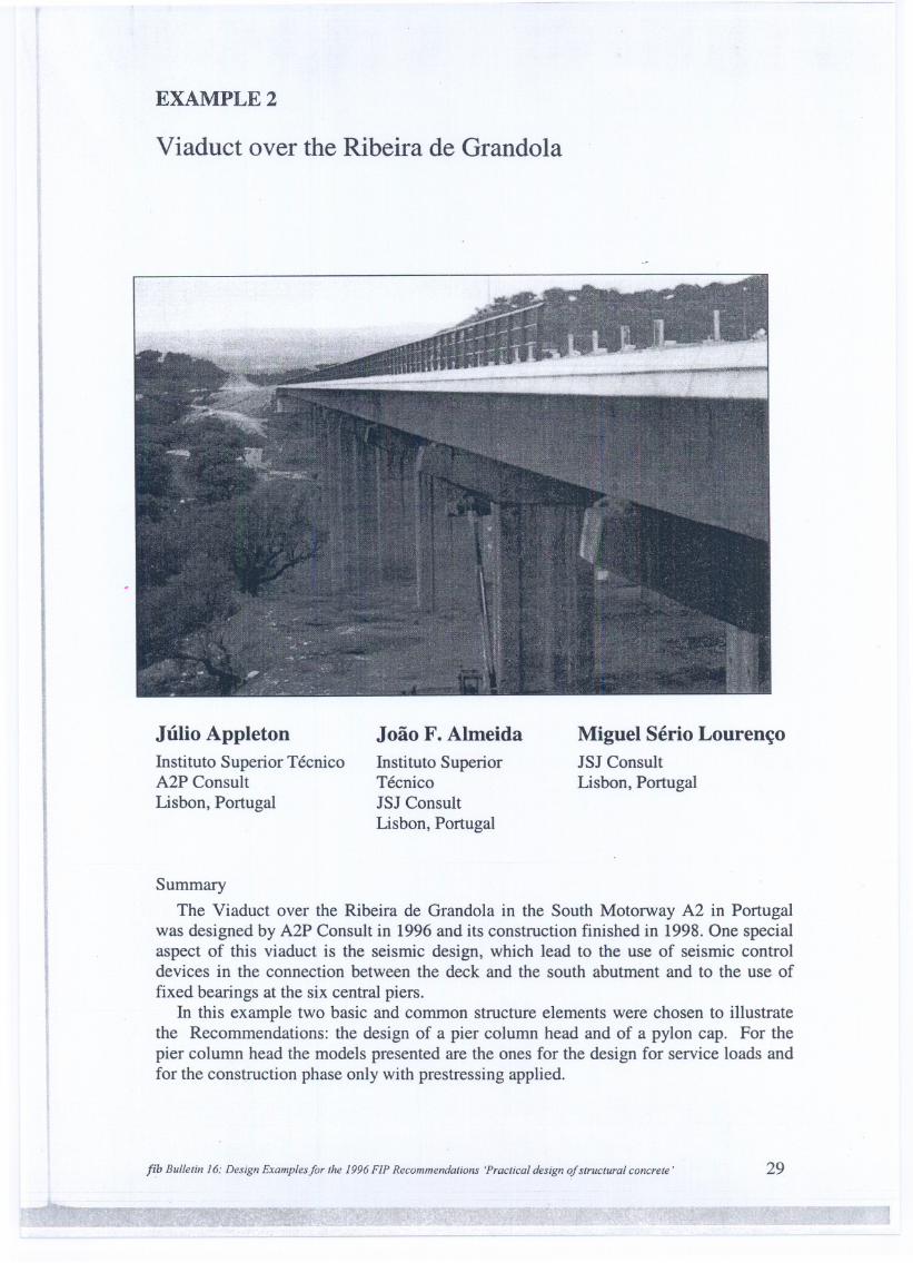
EXAMPLE 2
Viaduct over the Ribeira de Grandola
Júlio AppletonInstituto Superior TécnicoA2P Consult
Lisbon, Portugal
João F. AlmeidaInstituto SuperiorTécnicoJSJ Consult
Lisbon, Portugal
Miguel Sério LourençoJSJ ConsultLisbon, Portugal
Summary
The Viaduct over the Ribeira de Grandola in the South Motorway A2 in Portugalwas designed by A2P Consult in 1996 and its construction finished in 1998. One specialaspect of this viaduct is the seismic design, which lead to the use of seismic controldevices in the connection between the deck and the south abutment and to the use offixed bearings at the six central piers.
In this example two basic and common structure elements were chosen to illustratethe Recommendations: the design of a pier column head and of a pylon capo For thepier column head the models presented are the ones for the design for service loads andfor the construction phase only with prestressing applied.
fib Bullel;n 16: Des;gn Examplesfor lhe 1996 F1P Recommendal;ons 'Pracl;cal des;gn ofslruclural concrele' 29

Ur . ,
1 Description of the structure .
This viaduct has a totallength of 620.50 m with spans of 34.00 m + 13 x 42.50 m +34.00 m and two twin decks ofvariable width from 18.85 m to 21.10 m.
Each deck is a prestressed concrete slab with two longitudinal prestressed beams,3.20 m high.
The columns have an hollow section with externa! dimensions of 5.00 m x 2.20 marid 0.35 mIO.70 m thick walls. At the top a column head gives support for the deckbeams.
VERTICAL SECTION
0.= ALCACEJIDO 8AL44.0 42.50 4..
SECTION A. A'
Fig. 1: Geometry of the structure
2 Column head - design for service loads
This example refers to the calculation of the column head and it is an illustration ofthe FIP Recommendations chapter 6.5.2.3. Corbels.
The load transferred by each beam is F = 16 095 kN and the dimensions of thecolumnheadare presentedin Fig. 2.1.
30 2 Viaduct over the Ribeira de Grando/a
----- == --=

COLUMN HEAO
4.47
Fig. 2.1: Geometry of the corbel
2.1 Design model
Design ca1culations according to chapter 6.5.2.3
n-I
I
Fig. 2.2: Design model
fib Bulletin 16: Design Examplesfor the 1996 FIP Recommendations 'Practical design ofstructural concrete' 31
'!Y~'!IIp r
--- -- --- - --- --
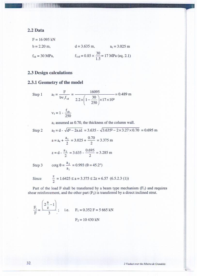
_72.2 Data
F =16095 kN
b =2.20 m,
fck= 30 MPa,
d = 3.635m, ac= 3.025m
30fIcd= 0.85x -= 17MPa (eq.2.1)1.5
2.3 Design calculations
2.3.1 Geometry of the model
Step 1
ai = F = (1:) - 0.489mbvJ cd 2 2 x 1- - x 17X103
. 250
fCk
VI= 1- 250
Step 2
aI assumed as 0.70, the thickness of the column wa11.
a2=d- .Jd2-2a.aI =3.635- .J3.6352-2x3.27xO.70 =0.695m
ai 0.70a = ac+ - =3.025 + - =3.375 m2 2
a2 0.695z =d - - =3.635 - - =3.285 m2 2
Step 3a
cotg 9 =-2. =0.993 (9 = 45.2°)ai
Sincez- =1.6425 ~ a =3.375 ~ 2z =6.57 (6.5.2.3 (1))2
Part of the load F shall be transferred by a beam type mechanism (FI) and requiresshear reinforcement, and the other part (F2)is transferred by a direct inclined strut.
i.e. FI =0.352 F =5 665 kN
32. 2 ViaducI over lhe Ribeira de Grandola
I..

2.3.2 Transfer of load FI
Transverse reinforcement (FI - Vcc) - 6.5.2.3.(1)To be distributed over
zaw = 0.85 a - - = 2.0475m
4
From the figure
FI 5665Vcc= - . tga= - xO.5963=2182kN
tgf3 1.548
FI - Vcc = 5665 - 2182 = 2 767 kN/m::; As~ .fSYdaw 2.048 s
For fsyd= 348 MPa ~ Asw ~ 48.9 cm2/m (distributed in aw)s
2.3.3 Strength of the inclined strut at load transfer F (node NI)
This check is satisfied if the width of the bearing plate aFfulfils
x
[
VI
]aF~ - cos 82
sin 82 0.6cos 82a
cotg 82 = - =1.027 ; x =0.40 mz
ap~ 0.7631 m (bearing plate provided with 0.90 m)
2.3.4 Transfer of load F (node NI)
TI =F cotg 8 =15 800 kN::; Fspr
Fspr (6 cables of 19 strands 1.4 cm2/each, fspk=1 670 MPa) =23 180 kN
2.3.5 Check of node NI
According to 5.6.2. - CCC Node, considering the effect of the prestressing anchorage:
(eq. 3.20)
(eq.5.19b)
092Aco=1tx ~ =0.636m2
4
A1.782
2 49 2cI =1t X - =. m
4
fib Bulle/in 16: Design Examplesfar lhe 1996 FlP Reeommenda/ians 'Prae/ieal design afs/rue/ural eanere/e' 33
. - ...,.. ~, ' .- -.. ~....-.-...

- - - - -- - - - -
16095 =25 306creO= 0.636 ~ 1.2 x 17 x 103~ 2.49 =40 364.4 kN/m20.636
~ 3.88 x 17 x 103=65 960 kN/m2
2.3.6 Check of node N2
According to 5.6.2. -CCC Node.
Ff JE
clcreO= - ~ led - (5.20)
bx ai Aco16095
creO= = 10451 kNl m2~ fled.l = 17000 kN/m22.2xO.70
(incorporated in Step 1 - see 2.3.1).
2.3.7 Check of inclined strut (at node N2)
According to 5.3.2.:
This verification is not required if the nodes are checked. It is presented to illustratethe recommendations:
VI =0.88
~ V2 fed V2= 0.8 1F
Cw= - =22324kNsinS
Xc (at node N2) =0.986
b =2.2 m
22324cre= =10 291.3 ~ 0.8 x 17 x 103=13.6 MN/m20.986 x 2.2 I
34.2 Viaducl over lhe Ribeira de Grandola

.,.....-
3 Prestressing in the column head -Model for construction phase
3.1 Introduction
Prestressing in the corbel was designed imposing no tension under rare combinationof loads (P' o = 18183 kN). As a consequence, tension occurs, temporarily, duringconstruction phase, at the bottom region of the corbel. -~
3.2 Geometry and loads
Prestressing cables are modelled by a resultant cable and the cable-Iayout issimplified by considering a bilinear profile. Fig. 3.1 shows the geometry of the corbel,the bending stresses at the central zone and the equivalent effects of the cable-Iayoutconsidered (anchoring and deviation forces).
-7936.8 kN/m2
1
4810.317kN t4810.317kN
I' 1.89 .1
3632.1kN/m2
~ ~83 kN
....-«>..-j
Fig. 3.1: Geometry and loads
3.3 Geometry of the model
The model presented in §6.5.7.1 should be adapted to fit with the geometry of thecorbel (Fig. 3.2). The position of TI and Cz is defined by the centroid of, respectively,the tension and compression zones of the stresses diagram. C3 is related with thedeviation of the tension bottom force and Cz should split in three parts, to equilibrate theanchoring and the deviation forces. Local splitting forces near the prestressing anchorare not represented.
jibBullelin 16: Design Examplesfor lhe 1996 F1P Recommendalions 'Praclical design qfslruclural concrele' 35
- ~------------ - - - -- - - -

-7936.8!4810.317 f4810.317
<D
IFig. 3.2: Geometry ofthe model
The inclination of C3 is not predefined having no significant influence on the tensionforces in ties T4 and T9. In the present case the direction of C3leads to similar TI and T4forces.
The modeI presented before can be refined following the principIes of the generalmodel proposed in §6.5.7.1. As illustrated in Fig. 3.3, the stresses compression zoneshould then be divided in three blocks: the first one (C2) is equivalent to the tensionforce (TI), and the remaining part, having a force resultant equivalent to the prestressingforce, further sub-divided in the zones above and below the prestressing cable (C3 andC4). .
! 4810.317-7936.8
&=
~---~-- ~--- -~~ @I@ ---
,..JiL_ Q); (j2----- - ""1'\
(!)\\
Fig. 3.3: Refined model
36
"
11~I
.,
1I
2 Viaducl over lhe Ribeira de Grando/a
==
Element Force[kN]
1 48162 -229993 -25584 48165 -41396 -100687 -84218 -85279 2600
Element Force[kN]
1 48162 -48163 -148244 -33595 4816
. 6. -25587 -48168 -63089 -417310 -878511 -986312 191813 -1918
,.....
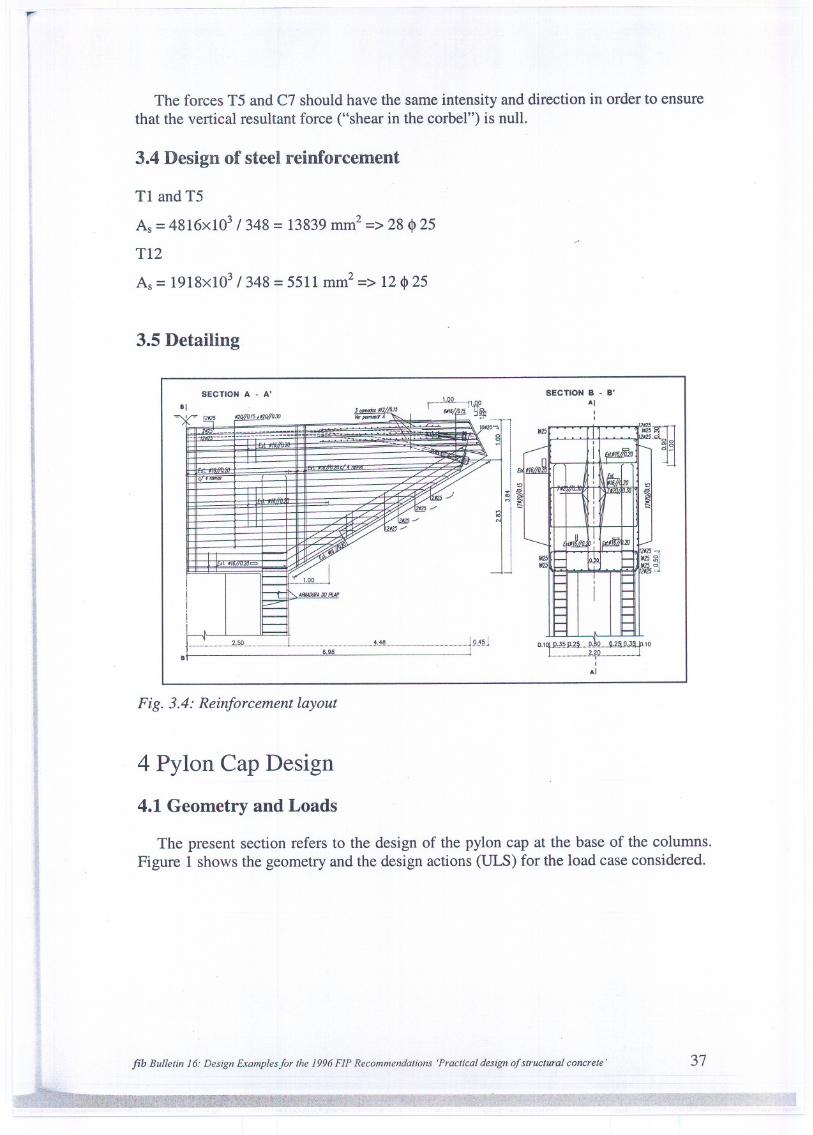
The forces T5 and C7 should have the same intensity and direction in order to ensurethat the vertical resultant force ("shear in the corbel") is null.
3.4 Design of steel reinforcement
TI and T5
As =4816xl03 / 348 =13839 mm2 =>28 «I> 25
T12
As =1918x103 / 348 =5511 mm2 =>12 «I> 25
3.5 Detailing
-
SECTION B -B'AI
SECTION A -A'
Izm
~IIZS:;!1'Z5ó'Zl2j...
~,§.!L J m.H.~ m J9"~§..I
6.98
0.1~.,ml,.2! !!,.~9 9.2~U~~f 'O2.201....-----
IAI
8
Fig. 3.4: Reinforcement layout
4 Pylon Cap Design
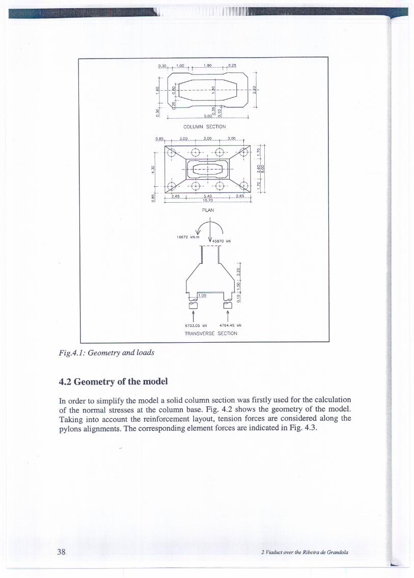
4.1 Geometry and Loads
The present section refers to the design of the pylon cap at the base of the columns,Figure 1 shows the geometry and the design actions (ULS) for the load case considered.
fib Bulletin 16: Design Examplesfor the 1996 F1P Recommendations 'Practical designofstructural concrete' 37
------
---
.Q,~9.t.t.-lcQ9t t 1.,~L t-tQ,~~
g
f
~- _~t g --
~
- -
_
...: dI ...: N
'"N _
. U') ...u ,.~ '1 oci1-_m m !LQ9.:'__~L ~
COLUMN SECTION
°..,...
°":
-'+-8-+'-
01
°"'0N<O
~+-' \; ,'1"+ -. .-"t++-. .."t-t t -.
, .. ,~+ '..+
f - i:~~'~~==:::___:=!1~j~===.I=====L=t
PLAN
LI
i6703.05 kN 4764.45 kN
TRANSVERSE SECTION
FigA.I: Geometry and loads
4.2 Geometry of the model
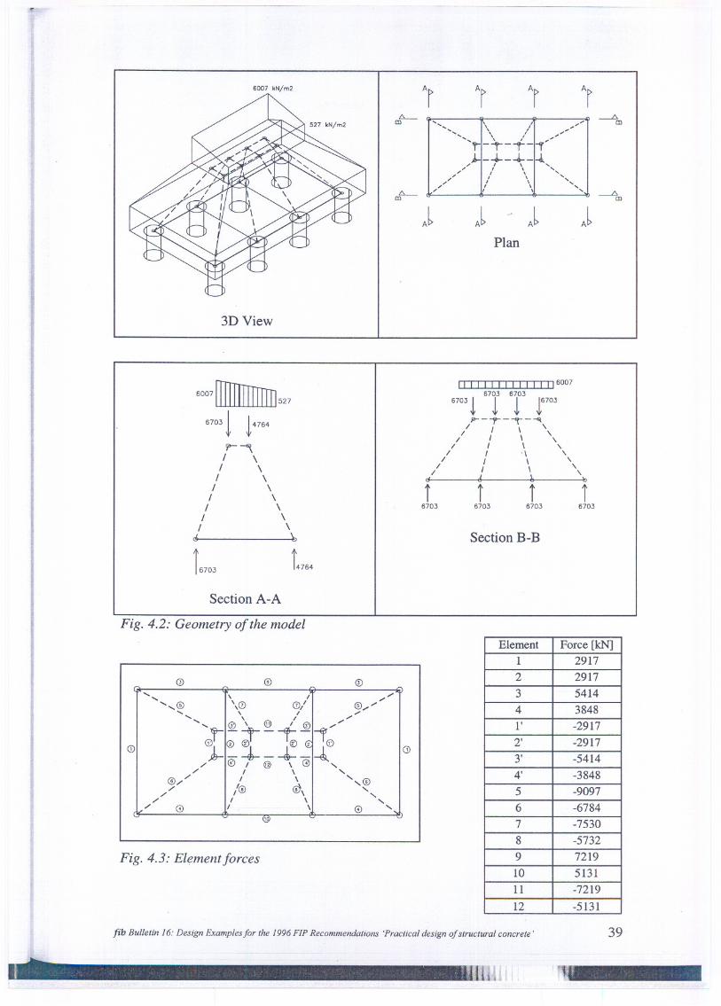
In order to simplify the model a solid column section was firstly used for the calculationof the normal stresses at the column base. Fig. 4.2 shows the geometry of the modeI.Taking into account the reinforcement layout, tension forces are considered along thepylons alignments. The corresponding element forces are indicated in Fig..4.3.
38 2 Viaduct over the Ribeira de Grando/a
~== ........
6007 kN/m2
3D View
.-.-.-.-
.-.-.-.-
J J JJPlan
6007 rnIIITIrITrn527
67031 14764
9-""",I \
I \I \
I \I \
I \I \
I \G \,
i6703
Section A-A
Fig. 4.2: Geometry ofthe modei
Fig. 4.3: Element forces
II I I I I I I I I I I I 1160076703 6703
6703! ! ! !6703,I>--"'f""-""'t"-~
I I \ '/ I \ \
I I \ ,I I .\ ,
I I \ 'I I \ '
/ d ~ \,i i i i
6703 6703 6703 6703
Section B-B
o
fib Bulletin 16: Design Examples for the 1996 FlP Reeommendations 'Praetieal design of struetural eonerete ' 39
"u--- - --
.... , I "...... "..
.... ....@ \0 0/ @".."".... , I "......
@\ @ /@"..
"......
.... "..
0't" 01"-€ "1"0)1- -.:J.--+-/ @ I @ \ <9 ,/ I \ ,
@// I \ ',@/ /@ <!\ ,/ ,/ I \ ,/ 0 I \ 0 "[.n'
Element Force [kN]1 29172 2917
3 54144 3848l' -29172' -29173' -54144' -38485 -90976 -67847 -75308 -57329 721910 513111 -7219
12 -5131

4.3 Steel reinforcement design
Longitudinal reinforcement
P;'máx= 7219x103 1348 = 20744 mm2 => 3 x 9 cj>32 (three layers)
Transversal reinforcement
P!.máx= 2917x103 1348 = 8382 mm2 => 2 x 9 cj>25 (two layers)
4.4 Check of node Nl
f1cd= 0.85xfck 1Yc= 0.85x30/1.5 = 17.0 MPa
fcd,eff=V2xflcd= 0.85x17 = 14.5 MPa (§5.6.4)
The equilibrium conditions lead to the equations:
0'1
(
4 u
J
2-= 1+-x-xtg<p xcos <p0'2 1t ai
SECTION A-A
Fig. 4.4: Node Nl
aI =1.0 m
u =0.25 m
<p=45°
0'1 =8.5 MPa
0'2 =12.9 MPa < fcd,eff
40.
---- ----
PLAN
and
2 Viaduct over the Ribeira de Grandola
_ _ i...

Anchorage of reinforcement (§2.4.1)
I =ti>X fYd =ti>x 348 ={
700mm,tI>25
b 4 fbd 4 1.05x2.9 900mm,tI>32
Since horizontal tension occurs in both directions the favourabl~ effect of the verticaltransverse pressure should not be considered. On the other hand, the anchorage lengthof longitudinal reinforcement can be reduced (As,req<As,prov,§5.6.4). In fact, the steelreinforcement design was performed considering for the maximum tension forceoccurring at the central zone and then extended alI along the longitudinal direction.
Ib=900 mm
As,req = 5414xlO3 / 348 = 15557 mm2 (Element 3)
As,prov= 3x9x804 = 21715 mm2
Ib,net= As,req/ As,provx Ib = 645 mm
In both directions the tension forces can be anchored inside the node.
4.5 Transfer of the strut force Cs across the interface (§5.5)
. 1t.a2Al =--L + a1 x u x tgcp=1.035 m2 (see figo 4.4)
4
T =fi! + T32 =6149.8 kN
'tfd =0.5 fctm+ 1.2 af = 9.25 MPa
af = 6703.05xlO-3 / 1.035 = 6.5 MPa
'tsd= T / A'] = 6149.8 X 10-3/ 1.035 = 5.9 MPa < 'tfd
fib Bulle/in 16: Design Examples for lhe 1996 FIP Reeommenda/ions 'Prae/ieal design of s/rue/ural eonere/e ' 41

4.6 Detailing
+1
I
IS
8ri
8ri
l_bsIIl*"*4J1o
BOTTOM REINFORCEMENT
~"
I' . ,'r+.-h~-,-'..f~/ I
I I II I I
1110 1 I_I-'-'--1- 1 8",I '" I .
;:SI ~;:Sl"§ ~I~ ~~l O) -.'"'r +--'
I
Fig. 4.5: Reinforcement layout
42. 2 Viaduct over the Ribeira de Grandola
,...
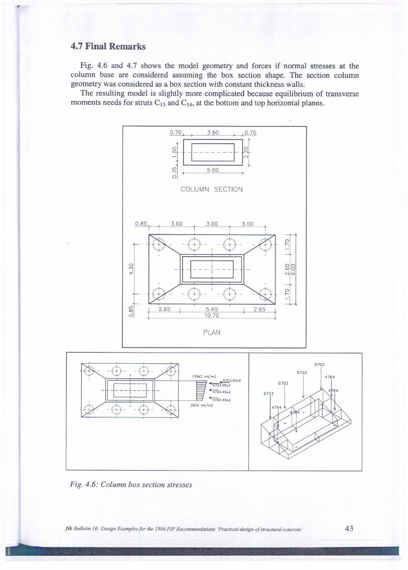
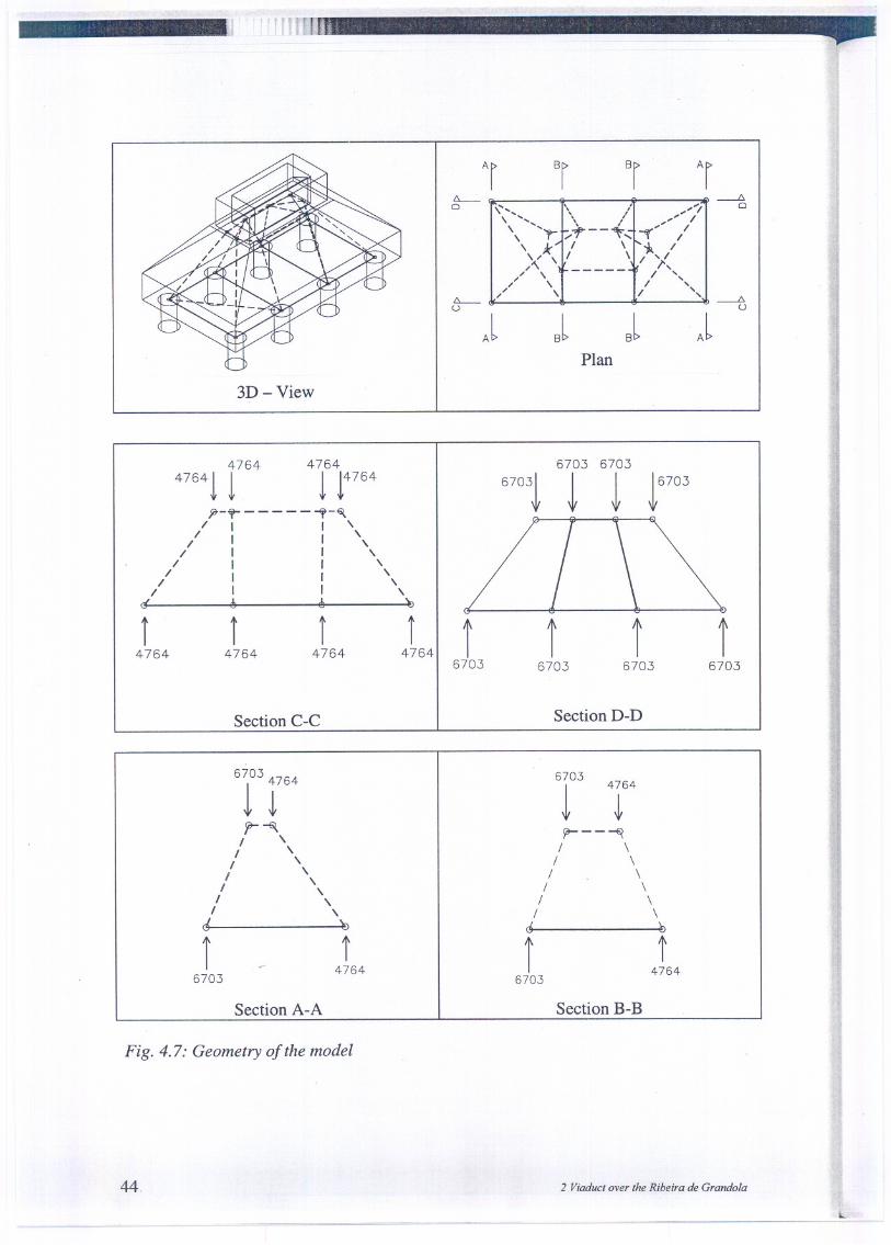
4.7 Final Remarks
Fig. 4.6 and 4.7 shows the model geometry and forces if normal stresses at thecolumn base are considered assuming the box section shape. The section columngeometry was considered as a box section with constant thickness walls.
The resulting model is slightly more complicated because equilibrium of transversemoments needs for struts C13and C14,at the bottom and top horizontal planes.
0.70I--' 3.60 1--'0.70
COLUMN SECTION
,-t-,_.-f.+.+.-
'...~ I
I ~...'\-.-t.+.+.-
'..~..,.'
o"
-1 t' I-.
01
0<DONc.O
O"
PLAN
-'.-I---t---I-.'-
6703
,-h-f+i--
".j--'
13547 kN/m2
~~3.05.26703.05.2
~4.45.2
~4,45.2
2835 kN/m2
Fig. 4.6: Column box section stresses
fib Bulletin 16: Design Examplesfor the 1996 FIP Recommendations 'Practical design ofstructural concrete' 43
li ~::
3D - View
4764 4764
47641 1 1 14764j7-ff-- - - - - ,,-~
/ I I '/ I I'
// I I"/ I I'
/ I I '// I I "
cr ~ ~ b
i4764
i4764
i4764
Section C-C
i4764
JPlan
6703 6703
67031 1 1 16703
I6703
I I6703 6703
I6703
Section D-D
6703
1 r64r-~I 'I 'I 'I 'I '
I 'I 'ct ' 'b
1~. f6703 4764
Section A-A
6703
1
4764
~yr---~
/ \/ \
/ \/ \
/ \/ \
ó b
I t6703 4764
Section B-B
Fig. 4.7: Geometry of the model
44. 2 Viaduct over the Ribeira de Grandola
L..

The resulting forces are not substantially changed (TI and T2 are no more equal),having no practical influence on the calculations previously presented.
. Fig. 4.8: Element forces
fib Bul/elin 16: Design Examplesfor lhe 1996 F1P Recommendalions 'Praclical design qfslruclural concrele'
- --
45
0) 0,
\', @\ ... ...\ '...\
01 @\ k I /@ @'. I_0 10
<@/,,/ \ ,---@--/ \0
/
/ 0 \»,@
Element Force[kN]
1 32742 25183 54124 3445l' -32412' -8193' -54834' -15205 -88276 -67297 -73248 -516413 -64214 -25229 695010 301811 -949912 -469