vibration analysis of circular arch element using curvature
TRANSCRIPT

Shock and Vibration 15 (2008) 481–492 481IOS Press
Vibration analysis of circular arch elementusing curvature
H. Saffaria, R. Tabatabaeia,∗ and S.H. Mansourib
aCivil Engineering Department, University of Kerman, Kerman, IranbMechanical Engineering Department, University of Kerman, Kerman, Iran
Received 20 July 2006
Revised 22 February 2007
Abstract. In this paper, a finite element technique was used to determine the natural frequencies, and the mode shapes of acircular arch element was based on the curvature, which can fully represent the bending energy and by the equilibrium equations,the shear and axial strain energy were incorporated into the formulation. The treatment of general boundary conditions doseneed a consideration when the element is incorporated by the curvature-based formula. This can be obtained by the introductionof a transformation matrix between nodal curvatures and nodal displacements. The equation of the motion for the element wasobtained by the Lagrangian equation. Four examples are presented in order to verify the element formulation and its analyticalcapability.
Keywords: Circular arch element, curvature, free vibration, natural frequencies, membrane-shear locking
1. Introduction
The study of free vibration is an important prerequisite for all dynamic response calculations for elastic systems.The natural frequencies and mode shapes can be obtained by free vibration analysis. The equations of motion for anelastic system with a finite number of degrees of freedom were derived through the application of the virtual-workprinciple for dynamic loading [19].
The most important subject discussed in this article is the vibration analysis of curved beams in the design ofthe structural components and the machine elements by using the finite element method. The development offinite elements for a curved beam has received considerable attention in recent years. A curved beam may can bemodeled by some straight beam elements and one can use the different finite element models to analyze the thinarch structures [4]. The models, varied in the polynomial orders, were used to interpolate displacement components.Choosing the three different combinations of shape function [2], carried out a static analysis of beams for the lateraland in-plane displacements [17]. used four different shape functions for the vibration curved beam problems [3].used a mixed trigonometric polynomial displacement field derived from an assumed constant membrane strain andlinear curvature strain field. Based on Timoshenko beam theory [7] derived trigonometric basis functions for curvedbeam element. A coupled polynomial displacement field has been presented by [15,16]. Besides the displacementfield [9,10], introduced an additional degree of freedom, which was the nodal shear strain. The analysis of curvedbeams derived by [14], included the effects of shear deformation and rotatory inertia. The same equation was givenby [1] without the considering of the effects of shear deformation [8]. gave a theory about analysis of thin-walledcurved box beam [12]. used several Fourier P-elements for the in-plane vibration of the thin and thick curved beam.Much of the attention has been focused to compensate the locking phenomena over the years since the locking
∗Corresponding author. Tel.: +98 9133429226; Fax.: +98 341 3211497; E-mail: [email protected].
ISSN 1070-9622/08/$17.00 2008 – IOS Press and the authors. All rights reserved

482 H. Saffari et al. / Vibration analysis of circular arch element using curvature
RS
W
θ
θ
CoordinateLocal
W
U
Fig. 1. Components of displacement in a typical curved beam.
concept was first introduced by improved numerical integration methods. These approaches are mostly in use, butit cannot represent the curvature of curved beam completely; therefore, following the method of [11], the presentauthors such as [18] used the formulation of a curved beam element with six nodes for curvature to compensatefor the undesirable shear or axial locking phenomenon completely. The formulation is capable of representing thebehavior of the curved beam with adequate accuracy and efficiency as compared to previous methods.
In the present work, a new formulation for vibration analysis of a circular arch element with three nodes forcurvature is presented. This formulation focuses on four major differences between the present study and the othersmethod. One of the four major differences is that the nodal parameters are not pure displacements, but the curvaturesin three nodes elements. Here, we use three nodes for curvature because components of mass matrix are derivedeasier than six nodes. Another differences is that in order to avoid membrane and shear locking phenomena, theshear and tangential strains are incorporated into the total potential energy by the force equilibrium equation. Themembrane locking occurs due to the fact that the element cannot bend without being stretched and shear lockingtakes place, because when the elements are subject to bending moments alone, the conventional lower-order elementsare unable to represent the condition of zero radial shear strains. Another major differences is that the total massmatrix includes the effects of shear deformation and rotatory inertia. The final difference has an interesting point inthis new formulation and that is the way it can easily be used to model curved beams and to analyze the free vibrationproblems. Incorporating these aspects into the new formulation resulted in a more efficient and less problematiccurved beam element. For this task, the radial and tangential displacements and sectional rotation are obtained byintegrating the assumed curvature filed. The treatment of general boundary conditions does need the considerationwhen the element employs the curvature-based formulation. This can be obtained by introduction of a transformationmatrix between nodal curvature and nodal displacements. The transformed matrix is obtained by eliminating thecomponents of the rigid body motion that is embedded in the two nodal displacements of typical circular archelement. The final finite element equilibrium equation is written in terms of the displacement components of thetwo-edge nodes only. The equation of motion for the element is obtained by the Lagrangian for dynamic loading.The formulation will be applied to four types of problems to verify the concept employed and its numerical resultsare given in tabular form that are compared with the known results obtained in other approaches.
2. General equations of arch element in the polar coordinates
The circular arch element with the radius of curvatureR and arclengthL loaded in plane is shown in Fig. 1. Theradial displacement,W , the tangential displacement,U , and the rotation,θ, are also shown in this figure. Thesecomponents are related to the curvatureκ, the shearing strainγ, and the tangential strainε, respectively by:
κ =∂θ
∂S, γ =
∂W
∂S− θ +
U
R, ε =
∂U
∂S− W
R(1)
The bending moment,Mb, the shearing force,Vb, and the axial force,N , are also related to the components of strain:
Mb = EIκ, Vb = nGAγ, N = EAε (2)
The equilibrium conditions of a small element in a circular arch takes the final form:

H. Saffari et al. / Vibration analysis of circular arch element using curvature 483
R
tm
S
r
κ1
κ2
κ3
L
Fig. 2. Nodal curvatures and applied loads in a 3-node circular arch element.
∂Mb
∂S+ Vb = 0,
∂Vb
∂S+N
R= 0 (3)
Using the Eqs (2), (3) shearing and the axial strains can be expressed in terms of the curvatureκ, by
ε =IR
A·(
1∂S2
∂2κ
), γ = − EI
GAn· 1
∂S∂κ
(4)
To determineθ, W andU , we substitute the Eq. (4) in Eq. (1) and the relationship between the rotationθ andcurvatureκ obtained from Eq. (1) as:
θ =
S∫0
κdS + Cθ (5)
WhereCθ is the constant of integration. The radial displacement is determined by the following equation, whichresults from Eqs (1–4):
∂W 2
∂S2+
1R2
·W = κ−(EI
GAn+I
A
)· 1
∂S2
∂2κ
(6)
The solution forW consists of the homogeneous and particular parts. The homogeneous solution has sinusial termsand two integration constants; the particular solution is a function of the curvature since there appearκ and 1
∂S2
∂2κ
on
the right-hand side of the Eq. (6):
W = (Wh +WP ), Wh = CW1 · CosS
R+ CW2 · Sin
S
R, WP =WP (κ) (7)
The three constant appearing in the Eqs (5) and (7) shows the components of rigid-body motion of the curvedelement. Finally, the tangential displacement is determined by the results of the Eqs (1–4):
U = R ·(θ − ∂W
∂S− EI
GAn· 1
∂S∂κ
)(8)
2.1. Interpolation of curvature κ, and other components of the displacement
Now, the interpolation process for curvature is to be carried on. It is worth noting here before the formulation thatcurvature should be interpolated with the order equal or higher than 2. A 3-node element for the curvature sincethe polynomial functions for the interpolation of the curvature with the order equal to two is presented in this paper.When the curvature in the element is interpolated as shown in Fig. 2, the following equations holds:
κ = {Hκ} · {V }, {V } = [κ1, κ2, κ3]T , {Hκ} = [hκ1 , h
κ2 , h
κ3 ] (9)

484 H. Saffari et al. / Vibration analysis of circular arch element using curvature
hκ1 = 1 − 3
S
L+ 2
(S
L
)2
, hκ2 = −S
L+ 2
(S
L
)2
, hκ3 = 4
S
L− 4
(S
L
)2
(10)
Equation (9) in Eq. (5) gives the sectional rotation as:
θ = {Hθ} · {V } + Cθ, {Hθ} = [hθ1, h
θ2, h
θ3] (11)
Also the radial displacement is given by Eq. (9) in Eq. (7) as shown below:
W = {HWP } · {V } + CW1 · CosS
R+ CW2 · Sin
S
R, {HWP } = [hWP
1 , hWP2 , hWP
3 ] (12)
Finally, the tangential displacement is written by Eq. (8) as shown below:
U = {HU} · {V } +R · {Cθ} + CW1 · SinS
R− CW2 · Cos
S
R, {HU} = [hU
1 , hU2 , h
U3 ] (13)
2.2. Transformation matrix between nodal curvatures and nodal displacements
When nodal curvatures(V ) are used for the interpolation, it is not easy to use the boundary conditions given asdisplacements. Therefore, we must consider a circular arch element with two nodal displacements in which the sixboundary conditions are given at the nodes of the element as shows in Fig. 3. When the components of rigid-bodymotion embedded in each nodal displacement are eliminated, the relations between nodal displacements(∆), andnodal curvatures can be found by using the following Eqs (11–13). Note that the three constantsC θ,CW1andCW2
appearing in the equations represent the rigid-body motion components. With the components of the rigid-bodymotion eliminated [19]:
θ1 = {Hθ |0 } · {V } + Cθ = Cθ (14)
W1 = {HWP |0 } · {V } + CW1 (15)
U1 = {HU |0} · {V } +R · Cθ − CW2 (16)
θ2 = {Hθ |L} · {V } + Cθ (17)
W2 = {HWP |L} · {V } + CW1 · CosL
R+ CW2 · Sin
L
R(18)
U2 = {HU |L} · {V } +R · Cθ + CW1 · SinL
R− CW2 · Cos
L
R(19)
or in the matrix form relationship between the nodal curvatures and nodal displacements can be obtained by:
[Tκ] · {V } = [TU ] · {∆} (20)
where
{∆} = [W1, U1, θ1,W2, U2, θ2]T (21)
and
[Tκ] =
HWP |L · V −HWP
∣∣0CosL
R +HU
∣∣0Sin L
R
HU
∣∣L · V −HWP
∣∣0Sin L
R −HU
∣∣0CosL
RHθ|L
(22)
[TU ] =
−CosL
R Sin LR −R · Sin L
R 1 0 0
−Sin LR −CosL
R −R · (1 − CosLR ) 0 1 0
0 0 −1 0 0 1
(23)

H. Saffari et al. / Vibration analysis of circular arch element using curvature 485
W2
U2
W1
U1
θ1
θ2
R
L
Fig. 3. Nodal displacement at 3-node circular arch element.
The transformation matrix, which relates the curvature vector at the three nodes and the displacement vector attwo-nodes as shown in Fig. 3 can be expressed as follows:
{V } = [T ] · {∆} (24)
[T ] = [T−1k ] · [TU ] (25)
For static problems the total displacementsQ in the continuous element as Fig. 3 can be related to a finite numberof displacements selected at two nodes in boundary conditions. This relationship is expressed by a column matrixof [f ] as:
[Q] = [f ] · {∆}, [Q] = [W U θ ] (26)
and[f ] is the shape function matrix. By using the Eqs (20–25), components of matrix[f ] we get:
[f ] = [fW fU fθ ]T (27)
where
{fW } =({HWP } − {HWP |0} · Cos
S
R+ {HU |0} · Sin
S
R
)· [T ] + {HW0} (28)
{HW0} =⌊Cos
S
R− Sin
S
RR · Sin
S
R0 0 0
⌋(29)
{fU} =({HU} − {HWP |0} · Sin
S
R− {HU |0} · Cos
S
R
)· [T ] + {HU0} (30)
{HU0} =[Sin
S
RCos
S
RR ·(
1 − CosS
R
)0 0 0
](31)
{fθ} = {Hθ} · [T ] + {Hθ0} (32)
{Hθ0} =[0 0 1 0 0 0
](33)
Other components of the displacement can be obtained in terms of the nodal displacement vector and transformationmatrix above. The radial displacementW as shown in Fig. 3 can be written as follows:
W = {fW} · {∆} (34)
The tangential displacementU can be obtained,
U = {fU} · {∆} (35)
And the sectional rotationθ can be written as:
θ = {fθ} · {∆} (36)

486 H. Saffari et al. / Vibration analysis of circular arch element using curvature
3. Stiffness and mass matrix for the arch element
The strain energyUeand, kinetic energyTe (neglecting rotary inertia) of the arch element is given by,
Ue =12
L∫0
εT ·[EA 00 EI
]·ε · dS
Te =12
L∫0
ρ · A · (U2 + W 2) · dS(37)
Where the dots denote the derivatives with respect to timet, ρ is the mass density of the arch material, which isconsidered in Ref. [16]. The Lagrangian in terms of nodal quantities can be expressed as,
L = Te − Ue =12{q}T · [M ] · {q} − 1
2{q} · [K] · {q} (38)
The Euler-Lagrange equation for the curved beam under consideration become,
[M ] · {∆} + [K] · {∆} = {0} (39)
The equivalent mass matrix[M ] for the circular arch element , which is given by :
[M ] = ρ ·A∫v
[f ]T · [f ] · dS (40)
Now, let us useA as the area of the section for the element, the final form of the equivalent mass matrix can bewritten as:
[M ] = [MW ] + [MU ] + [Mθ] (41)
Where[M ] is defined by the relations :
[MW ] = ρ · A∫ L
0
[fW ]T · [fW ] · dS (42)
[MU ] = ρ · A∫ L
0
[fU ]T · [fU ] · dS (43)
[Mθ] = ρ · I∫ L
0
[fθ]T · [fθ] · dS (44)
As illustrated above, the Eqs (42–44) represented the mass matrix for the radial translation[MW ], the mass matrixfor tangential translation[MU ]and lastly they represent the mass matrix for rotation[Mθ].
and, the stiffness matrix can be calculated in Eq. (38) by,
[K] = [T ]T ·EI
L∫
0
{Hκ}T · {Hκ}dS + α
L∫0
{Bκ}T · {Bκ}dS + β
L∫0
{Qκ}T · {Qκ}dS · [T ] (45)
where
{Bκ} ={∂Hκ}∂S
, {Qκ} =∂2{Hκ}∂S2
, β = IR2
A , α = EIGAn (46)
Note that as the polynomial terms are integrated in calculating the stiffness matrix, the conventional Gaussianintegration scheme is applicable.

H. Saffari et al. / Vibration analysis of circular arch element using curvature 487
Table 1Natural frequencies (HZ) for a circular ring computed by two present element
R/h Mode 2 Mode 4Method Method
Present study Plane stress element Exact Present study Plane stress element ExactANSYS (Timoshenko 1955) ANSYS (Timoshenko 1955)
320 10.70 10.74 10.70 58.40 58.13 58.04250 13.70 13.74 13.70 74.82 74.40 74.28200 17.12 17.17 17.12 93.50 93.01 92.86150 22.83 22.87 22.83 124.70 123.97 123.81100 34.24 34.29 34.24 187.02 185.91 185.7280 42.80 43.00 42.80 233.70 233.15 232.1450 68.49 68.89 68.49 373.80 373.43 371.4340 85.59 85.83 85.49 467.13 465.04 464.3030 114.11 114.29 114.15 622.30 618.74 619.0620 171.10 171.56 171.22 931.12 928.16 928.5910 340.92 341.76 342.45 1837.97 1824.40 1857.185 671.52 675.67 684.89 3504.46 3460.00 3714.36
4. Determination of natural frequencies and mode shapes
The elemental stiffness matrix[K] and mass matrix[M ] are assembled to obtain global equation of motionEq. (39). Since the free vibration is harmonic, the displacements{∆} can be written as:
{∆} = {q} · eiωt (47)
where{q} is a column matrix of the amplitudes of the displacements{∆}, (ω) is the circular frequency of vibration,andt is the time. Using the Eqs 47) in (39) and then canceling the common factore iωt, we obtain:
(−ω2 · [M ] + [K]) · {q} = {0} (48)
That can be regarded as the equation of motion for a system that is undamped and free of vibration. The Eq. (48)since it has a nonzero solution for{q} it can be rewritten as:∣∣−ω2 · [M ] + [K]
∣∣ = {0} (49)
This last equation is a characteristic equation from which the natural frequencies of free vibrations can be calculated.
5. Numerical examples
To confirm the reliability of the present study, the natural frequencies of free vibration responses obtained from thenew formulation of circular arch element are compared with the existing literature and those from the conventionalfinite straight-beam and plane stress elements, respectively.
5.1. Free vibration of a circular ring
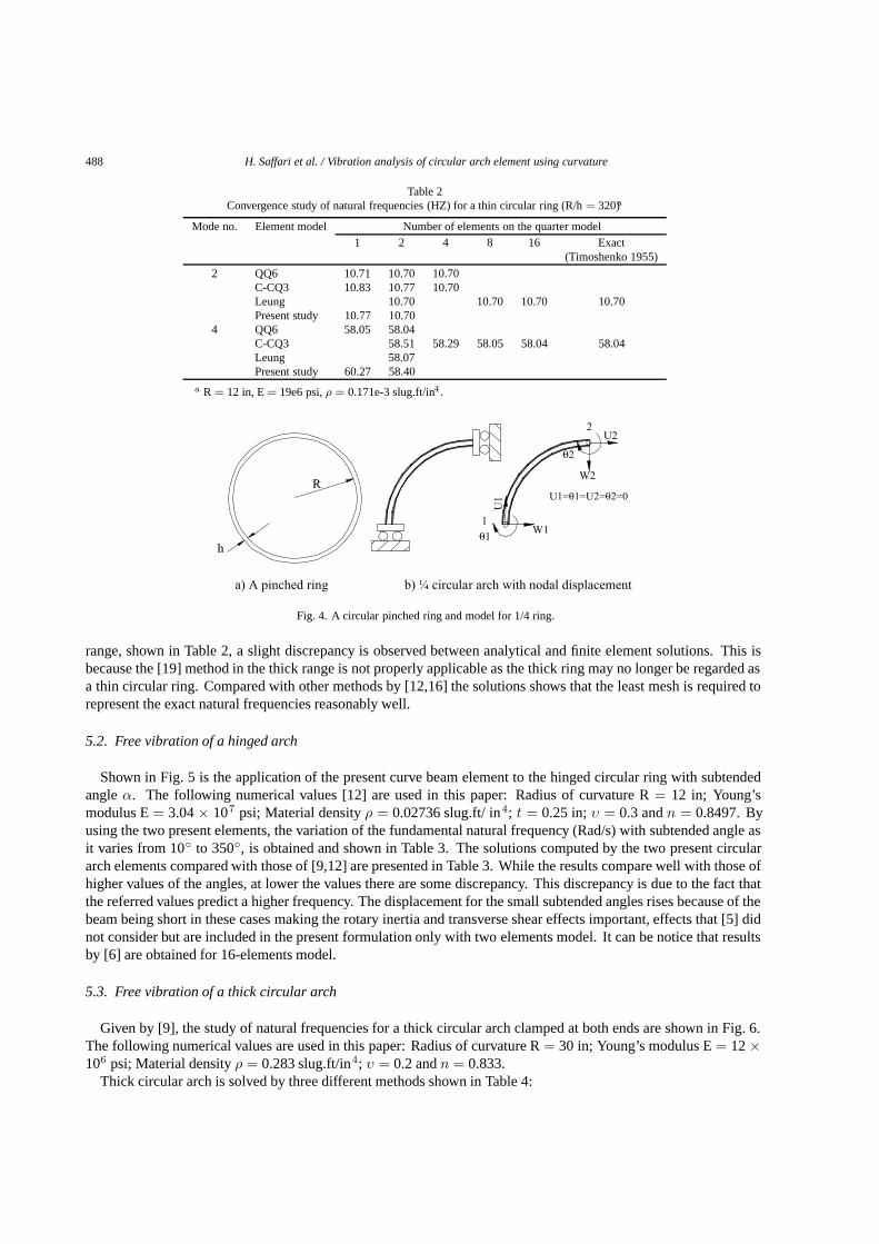
In order to investigate the representation of in extensional flexure behavior by the finite elements, the problemof vibrations of a circular ring is chosen and discussed in the preceding section [19]. gave the exact solutions ofthe natural vibration of a ring shown in Fig. 4. This problem is considered by several elements in the literaturessuch as [12,16] recently. The information used regarding the free vibration analysis of a circular ring are: Radiusof curvature R= 12 in = 0.3048 m; Cross-section A= 0.0375 in2 = 0.0009525 m2; Young’s modulus E= 19×106 lbf/ in2 1.31× 10¹¹ Pa; and the material densityρ = 0.171× 10⁻³ slug.ft/in4 1827 kg/m3. Only a quarterof the ring is modeled with symmetric boundary conditions as shown in Fig. 4. Two circular arch element with asubtended angle of 90◦ is used to predict the modes of the whole ring. Table 1 summarizes the results of the naturalfrequencies reasonably for two of the lowest symmetric modes of a thin circular ring with different ratio ofR/h.
The frequencies are obtained from the circular arch element and the exact solutions are given by [19]. Since thering with R/h = 320 is very thin, it is clear that the present curved element is free of locking. In the very thick
488 H. Saffari et al. / Vibration analysis of circular arch element using curvature
Table 2Convergence study of natural frequencies (HZ) for a thin circular ring (R/h= 320)a
Mode no. Element model Number of elements on the quarter model1 2 4 8 16 Exact
(Timoshenko 1955)
2 QQ6 10.71 10.70 10.70C-CQ3 10.83 10.77 10.70Leung 10.70 10.70 10.70 10.70Present study 10.77 10.70
4 QQ6 58.05 58.04C-CQ3 58.51 58.29 58.05 58.04 58.04Leung 58.07Present study 60.27 58.40
a R = 12 in, E= 19e6 psi,ρ = 0.171e-3 slug.ft/in4 .
Fig. 4. A circular pinched ring and model for 1/4 ring.
range, shown in Table 2, a slight discrepancy is observed between analytical and finite element solutions. This isbecause the [19] method in the thick range is not properly applicable as the thick ring may no longer be regarded asa thin circular ring. Compared with other methods by [12,16] the solutions shows that the least mesh is required torepresent the exact natural frequencies reasonably well.
5.2. Free vibration of a hinged arch
Shown in Fig. 5 is the application of the present curve beam element to the hinged circular ring with subtendedangleα. The following numerical values [12] are used in this paper: Radius of curvature R= 12 in; Young’smodulus E= 3.04× 10⁷ psi; Material densityρ = 0.02736 slug.ft/ in4; t = 0.25 in;υ = 0.3 andn = 0.8497. Byusing the two present elements, the variation of the fundamental natural frequency (Rad/s) with subtended angle asit varies from 10◦ to 350◦, is obtained and shown in Table 3. The solutions computed by the two present circulararch elements compared with those of [9,12] are presented in Table 3. While the results compare well with those ofhigher values of the angles, at lower the values there are some discrepancy. This discrepancy is due to the fact thatthe referred values predict a higher frequency. The displacement for the small subtended angles rises because of thebeam being short in these cases making the rotary inertia and transverse shear effects important, effects that [5] didnot consider but are included in the present formulation only with two elements model. It can be notice that resultsby [6] are obtained for 16-elements model.
5.3. Free vibration of a thick circular arch
Given by [9], the study of natural frequencies for a thick circular arch clamped at both ends are shown in Fig. 6.The following numerical values are used in this paper: Radius of curvature R= 30 in; Young’s modulus E= 12×106 psi; Material densityρ = 0.283 slug.ft/in4; υ = 0.2 andn = 0.833.
Thick circular arch is solved by three different methods shown in Table 4:

H. Saffari et al. / Vibration analysis of circular arch element using curvature 489
Table 3Fundamental frequency (rad/s) values of hinged circular archs computed by two present element for various subtended angles
Angle Fundamental frequency (rad/s)(degrees) Present study E1.1a E1.1b (Den Hartog 1928) (Heppler 1992)
(Krishnan et al. 1995) (Krishnan et al. 1995)
10 5862.21 5957.70 5874.30 21608.00 5849.9020 2869.65 2826.60 2823.10 5371.10 2830.2030 2538.53 2523.70 2345.20 2364.40 2339.7060 569.00 562.50 561.20 561.76 560.2490 229.50 230.65 230.40 229.95 229.77
120 115.20 116.33 116.30 115.74 115.64150 64.14 64.96 64.93 64.48 64.44180 37.70 38.25 38.24 37.89 37.87210 22.66 23.06 23.05 22.78 22.77240 13.60 13.87 13.87 13.67 13.67270 7.89 8.06 8.06 7.93 7.93300 4.15 4.27 4.27 4.19 4.19330 1.69 1.73 1.73 1.69 1.69350 0.49 0.51 0.50 0.49 0.24
Table 4Natural frequencies (rad/s) for a thick circular arch clamped at both ends with subtendedangleα = 90◦
R/h Mode 2 Mode 4Method Method
Present study Plane stress element Present study Plane stress elementANSYS ANSYS
50 28.61 28.87 56.29 54.3640 58.16 58.38 107.87 104.5130 118.84 119.27 169.58 163.6010 205.33 208.36 231.84 205.225 245.22 251.80 338.28 304.243 297.57 300.97 383.23 310.10
R
α
h
Fig. 5. A hinged circular arch with subtended angleα.
1. Using just two-element of present study.2. Modeling the beam as a plane stress elements3. Modeling the beam as a 20 straight beam elements [13].
The results obtained from the first method are compared to the other two methods as recorded in Table 4. Whilethat the present curved element is free of locking. In the very thick range, a discrepancy is observed between finiteelement solutions. This discrepancy happens because of the straight beam element in the thick range is not properlyapplicable as the thick ring may no longer be regarded as a thin circular ring [13]. When the solutions are compared

490 H. Saffari et al. / Vibration analysis of circular arch element using curvature
Table 5Natural frequencies (rad/s) for a quarter circular arch clamped at one end with subtended angleα = 90◦
R/h Mode 1 Mode 2 Mode 3Method Method Method
Present study Plane stress element Present study Plane stress element Present study Plane stress elementANSYS ANSYS ANSYS
300 0.313 0.316 1.51 1.51 4.79 4.78200 0.469 0.472 2.266 2.274 7.19 7.17100 0.939 0.936 4.531 4.530 14.39 14.3150 1.877 1.884 9.057 9.110 28.88 28.7125 3.753 3.757 18.07 18.09 58.31 56.74
12.5 7.497 7.508 35.75 35.81 117.22 110.656 15.52 15.54 70.97 71.19 217.76 202.263 30.32 30.31 120.91 122.90 278.95 262.32
1.5 55.82 55.48 163.99 174.98 310.62 298.85
R
h
α
Fig. 6. A thick circular arch clamped at both ends with subtended angleα.
R
h
Fig. 7. A quarter ring with fixed reaction.
with the others methods, it shows that the least mesh is required to represent the exact natural frequencies reasonablywell.
5.4. Free vibration of a quarter ring
Shown in Fig. 7 is a model that consists of two elements. One can make use of a program of vibration analysiswith new formulation to obtain the natural frequencies and mode shapes as the ratio of thickness to length of thebeam.
The following numerical values are used in this paper: Radius of curvature R= 30 in; Young’s modulus E= 12× 106 psi; Material densityρ = 0.283 slug.ft/in4; υ = 0.2 andn = 0.833. Comparing Table 5, the results of archshow good agreement with the existing finite element method.

H. Saffari et al. / Vibration analysis of circular arch element using curvature 491
6. Conclusions
Based on the curvature, a three nodes of the finite element model gives a satisfactory results for free vibrationbehavior of arches of the varied curvatures and thicknesses without locking is presented in this article; as wellas, the remedy of the undesirable shear/axial locking phenomenon. The element is actually a two-node elementwith displacements as nodal variables when it is transformed into the final shape from a three-node element for thecurvature in the beginning. The equation of motion of the element is written in final steps by Lagrangian equation.The natural frequencies and mode shapes curved structure is obtained by solving the characteristic equation ofmotion. To examine the convergence and accuracy of the present element, the vibration of some circular ring isanalyzed by making use of two present element. A computation was carried out to study the effect of curvature andboundary conditions on the fundamental frequency of circular arches. The accuracy of element is greatly improvedand the two present element can predict the lowest natural frequencies.
The results of the numerical examples shown is more accurate than other method, because it never utilizesapproximation. The results are also more useful from a practical point of view to the analysis of both thin andthick curved beam. It also makes the element readily usable in the vibration analysis of curved structures, which iscompatible with the existing plane stree elements.
Nomenclature
W Radial Displacement κ Curvature of ElementU Tangential Displacement θ Sectional RotationMb Bending moment γ Shearing StrainVb Shearing Force ε Tangential StrainN Axial Force n CoeffIcient ShearV Nodal Curvature {∆} Nodal Displacement[K] Stiffness Matrix ρ Density of the Body[D] Rigidity Matrix ω Circular Frequency[M ] Equivalent Mass Matrix t Time[f ] Displacement Shape FunctionsE Module of ElasticityI Moment of InertiaA Area of Section{q} The Amplitudes of the Displacements
References
[1] A.R. Archer, Small vibrations of incomplete circular rings,Int J of Mech Sci 1 (1960), 45–46.[2] D.G. Ashwell and A.B. Sabir, Limitations of certain curved finite elements to circular arches,Int J of Mech Eng 13 (1971), 133–139.[3] D.G. Ashwell, A.B. Sabir and T.M. Roberts, further studies in the application of curved finite elements to circular arches,Int J of Mech Sci
13 (1971), 507–517.[4] D.J. Dawe, Numerical studies using circular arch finite elements,Computers and Structures 4 (1974), 729–740.[5] J.P. Den Hartog, The lowest natural frequency of circular arcs,Philosophical Magazine 5 (1928), 400–408.[6] G.R. Heppler, An element for studying the vibration of unrestrained curved Timoshenko beams,J of Sound and Vibration 158 (1992),
387–404.[7] G.H. Heppler, J.S. Hansen and S. Timoshenko, beam finite elements using trigonometric basis functions,AIAA J 26 (1988), 1378–1388.[8] Y. Kim and Y.Y. Kim, Analysis of thin-walled curved box beam under in-plane flexure,J of Solids and Structures 40 (2003), 6111–6123.[9] A. Krishnan, S. Dharmaraj and Y.J. Suresh, Free vibration studies of arches,J of Sound and Vibration 186 (1995), 856–863.
[10] A. Krishnan and Y.J. Suresh, A simple cubic linear element for static and free vibration analyses of curved beams,Computers and Structures68 (1998), 473–489.
[11] P.G. Lee and H.C. Sin, Locking-free curved beam element based on curvature,Int J Numer Methods in Eng 37 (1994), 989–1007.[12] A.Y.T. Leung and B. Zhu, Fourier p-elements for curved beam vibrations,Thin-walled structures 42 (2004), 39–57.[13] R.H. Mc Neal and R.C. Harder,A Proposed Standard Set of Problems to Test Finite Element Accuracy, North-Holland, 1985.[14] S.S. Rao and V. Sundararajan, In-plane vibration of circular rings,J Appl Mech 36 (1969), 620–625.

492 H. Saffari et al. / Vibration analysis of circular arch element using curvature
[15] P. Raveendranath, G. Singh and B. Pradhan, A two-nodded locking-free shear flexible curved beam element,Int J Numer Methods in Eng44 (1999), 165–280.
[16] P. Raveendranath, G. Singh and B. Pradhan, Free vibration of arches using a curved beam element based on a coupled polynomialdisplacement field,Computers and Structures 78 (2000), 583–590.
[17] A.B. Sabir and D.G. Ashwell, A comparison of curved beam elements when used in vibration problems,J of Sound and Vibration 18(1971), 555–563.
[18] A. Sinaie, S.H. Mansouri, H. Saffari and R. Tabatabaei, A six node locking free curved beam element based on curvature,Iranian Journalof Science & Technology 27 (2003), 21–36.
[19] S. Timoshenko,Vibration Problems in Engineering, (3rd ed.), New York: Van Nostrand, 1955.

International Journal of
AerospaceEngineeringHindawi Publishing Corporationhttp://www.hindawi.com Volume 2010
RoboticsJournal of
Hindawi Publishing Corporationhttp://www.hindawi.com Volume 2014
Hindawi Publishing Corporationhttp://www.hindawi.com Volume 2014
Active and Passive Electronic Components
Control Scienceand Engineering
Journal of
Hindawi Publishing Corporationhttp://www.hindawi.com Volume 2014
International Journal of
RotatingMachinery
Hindawi Publishing Corporationhttp://www.hindawi.com Volume 2014
Hindawi Publishing Corporation http://www.hindawi.com
Journal ofEngineeringVolume 2014
Submit your manuscripts athttp://www.hindawi.com
VLSI Design
Hindawi Publishing Corporationhttp://www.hindawi.com Volume 2014
Hindawi Publishing Corporationhttp://www.hindawi.com Volume 2014
Shock and Vibration
Hindawi Publishing Corporationhttp://www.hindawi.com Volume 2014
Civil EngineeringAdvances in
Acoustics and VibrationAdvances in
Hindawi Publishing Corporationhttp://www.hindawi.com Volume 2014
Hindawi Publishing Corporationhttp://www.hindawi.com Volume 2014
Electrical and Computer Engineering
Journal of
Advances inOptoElectronics
Hindawi Publishing Corporation http://www.hindawi.com
Volume 2014
The Scientific World JournalHindawi Publishing Corporation http://www.hindawi.com Volume 2014
SensorsJournal of
Hindawi Publishing Corporationhttp://www.hindawi.com Volume 2014
Modelling & Simulation in EngineeringHindawi Publishing Corporation http://www.hindawi.com Volume 2014
Hindawi Publishing Corporationhttp://www.hindawi.com Volume 2014
Chemical EngineeringInternational Journal of Antennas and
Propagation
International Journal of
Hindawi Publishing Corporationhttp://www.hindawi.com Volume 2014
Hindawi Publishing Corporationhttp://www.hindawi.com Volume 2014
Navigation and Observation
International Journal of
Hindawi Publishing Corporationhttp://www.hindawi.com Volume 2014
DistributedSensor Networks
International Journal of