vibration isolation in a free-piston driven expansion tube
TRANSCRIPT

18th Australasian Fluid Mechanics ConferenceLaunceston, Australia3-7 December 2012
Vibration Isolation in a Free-Piston Driven Expansion Tube
D. E. Gildfind1, R. G. Morgan1, and P. A. Jacobs1
1Centre for HypersonicsThe University of Queensland, St. Lucia, QLD, 4067, Australia
Abstract
The stress waves produced by rapid piston deceleration are afundamental feature of free-piston driven expansion tubes, andwave propagation has to be considered in the design process.For lower enthalpy test conditions, these waves can traversethe tube ahead of critical flow processes, severely interferingwith static pressure measurements of the passing flow. This pa-per details a new device which decouples the driven tube fromthe free-piston driver, and thus prevents transmission of stresswaves. Following successful incorporation of the concept in thesmaller X2 facility, it has now been applied to the larger X3facility, and results for both facilities are presented.
Introduction
The expansion tube class of hypersonic flow facility is uniquelycapable of producing short duration test flows up to 15 km/s, atgigapascal total pressures. The University of Queensland (UQ)has two expansion tube facilities; X2 has a total length of 23 mand was originally commissioned in 1995; X3 is much longerat 69 m, and was commissioned in 2001. Both facilities arepowered by free-piston drivers, which provide the total pressurecapability necessary to produce test flows ranging from super-orbital planetary entry conditions (6-15 km/s), to high Machnumber scramjet access-to-space conditions (3-5 km/s).
A schematic of the X2 facility is shown in Figure 1 and is usedto explain the operation of both UQ facilities. A massive pis-ton is accelerated along the compression tube by high pressurereservoir air, attaining a high velocity, and compressing heliumdriver gas ahead of it (possibly mixed with argon). The drivergas is initially separated from the downstream driven tube by asteel diaphragm, scored so that it ruptures in a clean and repeat-able fashion. Towards the end of the piston stroke the drivergas pressure is sufficient to rupture the diaphragm, initiating ashock in the driven tube and the subsequent downstream flowprocesses. Simultaneously, this high driver pressure applies alarge magnitude impulsive axial load to the tube.
Figure 1: Schematic of X2 expansion tube facility, shown toscale, with nozzle attached.
Secondary and tertiary light Mylar diaphragms are used to ini-tially separate downstream tube sections which may contain dif-ferent gases at different pressures. In basic expansion tube modethe test gas is contained between the steel primary diaphragmand a Mylar secondary diaphragm. A low pressure gas fills theremaining downstream acceleration tube and dumptank, whichincludes the test section. The primary shock first processes thetest gas. The shock ruptures the secondary diaphragm upon itsarrival, allowing the shock processed test gas to expand into thelow pressure acceleration tube. The test gas undergoes an un-steady expansion along the length of the acceleration tube, gain-ing significant total enthalpy, before eventually passing over themodel in the test section and providing the flow experiment.
Many high enthalpy conditions as well as scramjet conditionsbenefit from operation of the expansion tube with a shock-heated secondary driver [4]. This is a volume of helium con-tained at the beginning of the driven tube, between the primarydiaphragm and the test gas, and requires the use of a secondthin Mylar diaphragm. The secondary driver provides addi-tional shock strength for high enthalpy conditions, but is alsoused for relatively low enthalpy scramjet conditions to preventcorruption of the test flow by acoustic disturbances originatingin the free-piston driver (a noise mechanism originally identi-fied by Paull and Stalker [5]).
UQ’s X2 and X3 free-piston driven expansion tube facilities areroutinely used to produce super-orbital test flows, such as plan-etary entry between 6 and 15 km/s. At these speeds, the averageshock speed down the tube typically exceeds the speed of soundin steel, and the flow measurements of interest complete be-fore the arrival of mechanical stress waves from the free-pistondriver. However, by virtue of their immense total pressure capa-bility, these facilities are increasingly being utilised to simulatescramjet access-to-space flow conditions. Scramjet flow condi-tions typically entail average shock speeds through the driventube of approximately 2-3 km/s. Stress waves originating atthe driver, which travel down the steel tube at approximately5 km/s, will overtake the shock wave in these conditions. Thiscan present a particular problem in the acceleration tube, whererelatively high sensitivity pressure transducers are used sincepressures are low.
X2 and X3 use PCB sensors to make these pressure measure-ments. The PCB sensor comprises a stiff but deformable steeldiaphragm attached to an internal piezoelectric sensor crystalwhich produces a charge when it is stressed [1]. The diaphragmdisplaces under pressure loading, and a correlation between de-flection and charge can be used to measure pressure. However,when a PCB is subject to large accelerations, the diaphragmmay also displace relative to the crystal due to inertial effects.In such cases an erroneous pressure measurement may be made.The sensitive PCBs used for the acceleration tube have corre-spondingly more flexible diaphragms, and therefore are partic-ularly sensitive to forced accelerations of the sensor.
Following attempts to simulate scramjet flow conditions in X2,unacceptably noisy static pressure traces were measured in theacceleration tube. Figure 2 shows examples of three static pres-

sure traces for a Mach 12.5 flow condition. Transducers ‘at4’,‘at5’, and ‘n1’ are respectively located at 1.6, 1.9, and 2.7 mdownstream of the tertiary diaphragm (refer Figure 1). It canbe seen that large amplitude noise begins prior to the arrival ofthe primary shock, which would normally be evidenced by asudden rise in static pressure as the shock passes the transducer.The actual test flow static pressure is almost entirely obscuredby the noise, and very little useful information can be inferredfrom these traces. This is problematic, since knowledge of thetrue static pressure through the acceleration tube, particularlynear the tube exit, helps to characterise the test gas immediatelyprior to its arrival in the test section or nozzle inlet.
1.6 1.8 2 2.2 2.4 2.6 2.8 3 3.2 3.4 3.6 3.8−15
−10
−5
0
5
10
15
20
25
30
time (ms)
staticpressure
(kPa)
at4at5n1
Shock arrival at transducer
Mechanical vibrations
Figure 2: Acceleration tube static pressure transducer responsesfor Mach 12.5 flow condition x2-scr-m12p5-rev-1 from [2].
It was considered highly likely that the noise in Figure 2 wasdue to mechanical disturbances from the free-piston driver, andit was postulated that introducing compliance at one of the up-stream tube joins might reduce transmission of stress waves tothe acceleration tube. A new design concept was therefore pro-posed which would axially decouple X2’s driven tube at the sec-ondary diaphragm station tube connection.
A New Secondary Diaphragm Holder/Buffer for X2
In X2’s previous configuration, the thin Mylar secondary di-aphragm was held in place by clamping it between the upstreamand downstream tubes, simultaneously forming a rigid connec-tion between the tubes. In this arrangement, mechanical dis-turbances in the upstream tube are transmitted directly into thedownstream tube, like those evident in Figure 2.
Mechanical disturbances are associated with a rapid finite dis-placement vs. time profile of the upstream tube at the tube in-terface, which depends on the mass and geometric properties ofthe attached downstream tube. It would be expected that thisdisplacement would be a maximum if the downstream tube wasfully disconnected from the upstream tube. Although this isimpractical, there would be no transfer of the mechanical dis-turbance. However, the magnitude of the force transferred tothe downstream tube can be reduced significantly if a section ofcompliant material is located between the two tubes.
A new secondary diaphragm holder/buffer device was devel-oped for X2. Figure 3 shows a schematic of the device. Herethe new arrangement locates the Mylar diaphragm in an inde-pendent cartridge unit, and removes the requirement for a stiffclamping arrangement between the tubes. The upstream rubberbumper is a 6 mm thick ring of rubber which acts as a relativelysoft interface between the tubes. There is sufficient diametricclearance in the cavity containing this ring to permit approxi-mately 3 mm compressive displacement before the volume isfully blocked by the deformed rubber. Finally, o-rings ‘1’ and‘4’ in Figure 3(a) permit axial movement of the tube whilstmaintaining a vacuum seal. Since supporting the diaphragm and
sealing the tube no longer depend on a large compressive axialforce at the tube join, the secondary diaphragm station can nowbe assembled with minimal clamping force, and once assem-bled permits a small degree of relative tube movement withoutsignificant load transfer between tubes.
Flow direction
Mylar diaphragm
Diaphragm
holder
Bumper and
alignment piece
12
34
5
Connecting
sleeve
Rubber bumpers
Threaded attachment
(3 places)
Sliding
interface
Figure 3: Schematic of X2 diaphragm buffer/holder assembly.
The compliant rubber buffer material must be sized to ac-commodate deflections characteristic of the specific free-pistondriver configuration. There are two characteristic deflections ofthe tube during operation of the free-piston driver. The entiretube is supported by roller bearings, and is free to move axially.Since the piston moves forward during an experiment, conser-vation of momentum requires that the facility correspondinglyrecoil in the opposite direction. Loading of the downstream tubecannot be avoided since it eventually must recoil with the up-stream tube in this particular setup. However, this recoil actionoccurs over relatively long time scales and is not thought to in-duce accelerations in the tube wall of sufficient magnitude tointerfere with tube wall static pressure measurements to the ex-tent evident in Figure 2. In addition to the fundamental recoilmotion of the facility, there is additional transient loading of thetube, primarily due to the large impulsive load applied to thecompression tube by the decelerating piston. This loading canproduce strong longitudinal stress waves, and is thought to bethe primary source of the observed mechanical disturbances.
While the characteristic magnitude of these deflections wasnot determined prior to designing this new device, referencewas made to tube recoil data which is routinely recorded dur-ing experiments. Using X2’s recently commissioned tunedlightweight free-piston driver [3], the tube recoil has been mea-sured experimentally to be between 4 and 5 mm, which occurssteadily over approximately 20 ms. In comparison to this to-tal tunnel recoil, transient displacements at the secondary di-aphragm due to piston impulse loading would be expected toless, thereby probably making the 3 mm of travel incorporatedinto the new design sufficient.
Referring to Figure 3, there is an additional rubber bumper lo-cated downstream of the secondary diaphragm. This is also de-signed to act as a compliant buffer against axial loading due torecoil motion of the tube. While this buffer cannot accomodatethe entire tube recoil motion, it has sufficient travel to accomo-date higher speed but lower magnitude deflections.
Results with X2
Figure 4 shows an example of experimentally measured accel-eration tube wall static pressure traces when the new diaphragmholder/buffer assembly is installed. These results are for thesame Mach 12.5 flow condition considered in Figure 2. It canbe seen that the mechanical disturbances identified in Figure 2
are practically eliminated, and the arrival of the shock at eachtransducer is now evident.
1.6 1.8 2 2.2 2.4 2.6 2.8 3 3.2 3.4 3.6 3.8−15
−10
−5
0
5
10
15
20
25
30
time (ms)
staticpressure
(kPa
)
at4at5n1
Shock arrival at transducer
Figure 4: Acceleration tube transducer responses for Mach 12.5flow condition x2-scr-m12p5-rev-1 [2], after installation of newdiaphragm holder and buffer arrangement (see Figure 3).
In addition to improving the quality of the recorded pressuretraces, containing the diaphragm in a separate cartridge unit en-sures that the thin diaphragm is seated properly and fully sup-ported; this, in turn, improves the quality of the vacuum sealobtained across the diaphragm, and improves the operationalreliability. These two benefits alone justify the additional shot-by-shot turnover effort associated with the new design.
The X3 Expansion Tube
The X3 expansion tube is the larger of UQ’s two expansiontubes. With a length of approximately 69 m and an acceler-ation tube bore diameter of Ø182.6 mm (compared to 23 mlength and Ø85.0 mm bore for X2), X3 can achieve equiva-lent flow conditions to X2, but can accommodate much largermodels and provide much longer duration test times. In recentyears X3 has undergone several upgrades, including the devel-opment of a new single-stage free-piston driver, modificationto incorporate a contoured Mach 10 nozzle, a new test sectionand dumptank, improved instrumentation and data acquisition,and various other upgrades. At the time of writing a number ofshots have been successfully performed with the upgraded fa-cility. The focus of current commissioning and flow conditiondevelopment has been new scramjet test conditions in supportof the SCRAMSPACE project. Steady Mach 10 test flows usingthe new nozzle have already been achieved, with total pressureand test time exceeding 100 MPa and 1 ms respectively.
For X3, as with X2, it is very important to obtain reliableand high quality static pressure measurements of the test flowthrough the acceleration tube. For these new scramjet flow con-ditions, similar mechanical disturbances have been observed inthe pressure traces through the acceleration tube of X3. Giventhe success of the new diaphragm holder/buffer assembly in X2,a similar concept was adapted to X3.
In X3’s previous configuration, diaphragms were clamped be-tween adjacent tube sections, and sealed by o-rings located ateach tube face. For a facility of X3’s size, any minor misalign-ment of two adjacent tube faces can result in uneven clampingforce on the diaphragm, resulting in leaks and even slippageof the diaphragm under pressure. Additionally, the diaphragmcan become unseated during assembly of the two massive tubesections, and subsequent problems may only become apparentonce the facility has been fully assembled and pumped down.
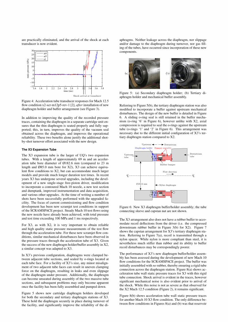
Figure 5 shows new cartridge diaphragm holders developedfor both the secondary and tertiary diaphragm stations of X3.These hold the diaphragm securely in place during turnover ofthe facility, and significantly improve the reliability of the di-
aphragms. Neither leakage across the diaphragm, nor slippageand/or damage to the diaphragm during turnover, nor gas fill-ing of the tubes, have occurred since incorporation of these newcomponents.
Figure 5: (a) Secondary diaphragm holder; (b) Tertiary di-aphragm holder and mechanical buffer assembly.
Referring to Figure 5(b), the tertiary diaphragm station was alsomodified to incorporate a buffer against upstream mechanicaldisturbances. The design of the new buffer is detailed in Figure6. A sliding o-ring seal is still retained in the buffer mecha-nism (o-ring ‘6’ in Figure 6), however unlike with X2, axialcompression is required to seal the o-rings against the upstreamtube (o-rings ‘1’ and ‘2’ in Figure 6). This arrangement wasnecessary due to the different initial configuration of X3’s ter-tiary diaphragm station compared to X2.
Bumper assemblyDiaphragm holder
Flow direction
Mylar diaphragm
Rubber bumper
182.6 mm
1
2
3
45
67
Figure 6: New X3 diaphragm buffer/holder assembly; the tubeconnecting sleeve and capstan nut are not shown.
The X3 arrangement also does not have a rubber buffer to acco-modate recoil deflections from the driver (i.e. the compresseddownstream rubber buffer in Figure 3(b) for X2). Figure 7shows the capstan arrangement for X3’s tertiary diaphragm sta-tion. Referring to Figure 7(a), recoil is transmitted through anylon spacer. While nylon is more compliant than steel, it isnevertheless much stiffer than rubber and its ability to bufferrecoil disturbances may be correspondingly poorer.
The performance of X3’s new diaphragm buffer/holder assem-bly has been assessed during the development of new Mach 10flow conditions for the SCRAMSPACE project. The buffer wasinitially assembled with no rubber, thereby ensuring a rigid tubeconnection across the diaphragm station. Figure 8(a) shows ac-celeration tube wall static pressure traces for X3 with this rigidtube connection. Shock arrival is evident in the traces, howeversignificant mechanical noise is also evident prior to arrival ofthe shock. While this noise is not as severe as that observed forthe X2 Mach 12.5 condition (Figure 2), it remains significant.
Figure 8(b) shows acceleration tube wall static pressure tracesfor another Mach 10 X3 flow condition. The only difference be-tween flow conditions in Figures 8(a) and (b) was that reservoir

Figure 7: X3 tertiary diaphragm arrangement. (a) diaphragmstation open; (b) diaphragm station closed.
pressure behind the piston was increased from 3.2 to 3.4 MPa(i.e. the piston was pushed slightly harder in Figure 8(b)); allother tunnel configuration parameters were the same. In Fig-ure 8(b), X3’s diaphragm buffer was loaded with four rubberrings with 24 mm total thickness. It can be seen that the rub-ber buffer has substantially removed mechanical noise from thestatic pressure traces, validating the design for X3.
11 12 13 14 15 16 17 18 19 20 21−10
0
10
20
30
40
time (ms)
stat
ic p
ress
ure
(k
Pa)
(a) Without diaphragm buffer (shot x3s400)
AT2 (TD+4.099m)
AT3 (TD+6.128m)
AT4 (TD+10.193m)
AT5 (TD+12.658m)
AT6 (TD+14.257m)
AT7 (TD+15.858m)
AT8 (TD+16.287m)
11 12 13 14 15 16 17 18 19 20 21−10
0
10
20
30
40
time (ms)
stat
ic p
ress
ure
(k
Pa)
(a) With diaphragm buffer (shot x3s401)
AT2 (TD+4.099m)
AT3 (TD+6.128m)
AT4 (TD+10.193m)
AT5 (TD+12.658m)
AT6 (TD+14.257m)
AT7 (TD+15.858m)
AT8 (TD+16.287m)
Figure 8: Acceleration tube transducer responses for a Mach 10flow condition in X3, (a) before and (b) after installation of anew diaphragm holder and buffer arrangement (see Figures 5 to7). Transducer locations are all located downstream from thetertiary diaphragm (TD) plane, by an amount TD+x as shown.
Interestingly, it can be seen in Figure 8(b) that use of the rub-ber buffer introduces high frequency mechanical noise to theAT2 and AT3 pressure traces prior to shock arrival. The causeof this noise has not yet been identified, however it is thoughtthat it may be due to the transient response of the diaphragmholder within the holder/buffer assembly; the holder is impactedby mechanical stress waves from the upstream tube, and isalso loaded by the normal shock wave (which causes the di-aphragm rupture). It is possible that the holder temporarily‘rattles’ around inside the holder cavity. The high frequencynoise is only observed in AT2 and AT3, and is not apparentin transducers located further downstream. X3’s accelerationtube is constructed from a number of tube sections connectedby threaded sleeves. AT3 is located in a tube segment, whereasAT2 is located in a heavier cross-section connecting sleeve; thereduced noise in AT2 may be due to the heavier cross-sectionof the sleeve. Transducers further downstream do not exhibitthis noise, possibly because the high frequency noise does notsignificantly transmit across the subsequent tube connections.
Initial experience with X3’s diaphragm holder/buffer assemblyindicates that it works most effectively when assembled withminimum pre-load to the rubber, although sufficient pre-loadmust be applied to compress o-rings ‘1’ and ‘2’ in Figure 6.Adopting a parallel o-ring seal at this interface (such as o-ring‘1’ in Figure 3 for X2) would remove this requirement andlikely improve the operation of the buffer.
The maximum compression of the diaphragm/holder buffer dur-ing operation of X3 was measured using deformable solder rodsglued between the upstream and downstream parts of the di-aphragm holder/buffer. When the buffer is compressed, the de-flected upstream face presents an irresistible deflection to thesolder rods, therefore any contact is observed later as deflec-tion/detachment of the rods. It was found that initial tighten-ing of the diaphragm station compressed the buffer between 1and 2 mm; after firing X3 at a Mach 10 condition similar tothose considered in Figure 8, the maximum total displacementwas later measured to be between 4 and 5 mm, indicating thatthe displacement during actual firing of the facility was approx-imately (5− 2) = 3 mm. This displacement is comprised ofmovement of the upstream tube and/or independent movementof the diaphragm holder. It nevertheless establishes a charac-teristic maximum deflection during operation. Considering therelative size of X2 compared to X3, the selection of 3 mm travelfor X2’s buffer appears to have been conservative.
Conclusions
New designs for X2 and X3 introduce devices at the secondaryand tertiary diaphragm stations, respectively, which mechani-cally decouple the tubes at these locations. A compliant bufferseparates the tubes, and a small amount of relative movement ofthe tube faces is permitted, thereby preventing transmission ofmechanical noise from the upstream free-piston driver. The re-sult is dramatically reduced signal noise. It has been found thatthe X2 design is better, since it does not require pre-loading ofthe diaphragm station to maintain vacuum seal. Improved oper-ation of the X3 apparatus is still being established.
Acknowledgements
The authors wish to thank: Mr B. Loughrey and Mr F. De Beursfor technical support; The Australian Research Council and TheQueensland Smart State Research Facilities Fund 2005 for sup-port and funding; The Australian Space Research Program andUQ for their funding in support of the SCRAMSPACE project
References
[1] PCB technical information, downloaded 1 Feb 2012.http://www.pcb.com/techsupport/tech pres.php .
[2] Gildfind, D.E., Development of High Total Pressure Scram-jet Flow Conditions using the X2 Expansion Tube, PhD the-sis, Department of Mechanical and Mining Engingeering,The University of Queensland, 2012.
[3] Gildfind, D.E., Morgan, R., McGilvray, M., Jacobs, P.,Stalker, R., and Eichmann., T., Free-Piston Driver Optimi-sation for Simulation of High Mach Number Scramjet FlowConditions, Shock Waves, 21, 2011, 559–572.
[4] R.G. Morgan, R.J. Stalker, Double Diaphragm Driven FreePiston Expansion Tube, 18th International Symposium onShock Waves, Jul 21-26, Sendai, Japan, 1991.
[5] A. Paull, R.J. Stalker, Test flow disturbances in an expan-sion tube, J. Fluid Mech., 1992, 245, 1992, 493–521.