vibration isolation system - standa · p.o. box 377 03012 vilnius, lithuania phone: +370-5-2651474...
TRANSCRIPT
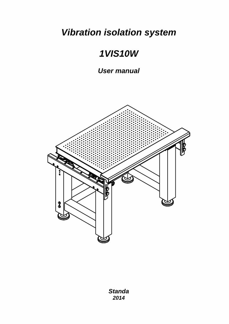
Vibration isolation system
1VIS10W
User manual
Standa
2014
P.O. Box 377
03012 Vilnius, Lithuania
Phone: +370-5-2651474
Fax: +370-5-2651483
E-mail: [email protected]
Manufacturer of Opto-Mechanical equipment for research, industry and education http://www.standa.lt
2
Table of contents
1. General information 3
1.1. Introduction 3
1.1.1. Safety 5
1.2. Location of the table 5
1.3. Air supply requirements 5
2. Mounting of the system 7
2.1. Assembly of the system 7
2.1.1. Safety 7
2.1.2. Assembly of the frame 7
2.1.3. Connection and installation of pneumatic vibration isolation components 8
2.1.4. Assembly of the support brace 9
2.1.5. Fitting the collector and the support plates 10
2.1.6. Assembly of the table 11
2.2. Preparation of the system for operation and vibration isolation of the table 12
2.2.1. Assembly of level controls 12
2.2.2. Connection of air supply pipes 14
2.2.3. Setting of level controls 15
3. Management of the system 16
3.1. Main principles 16
3.2. Adjustment of parameters of the system 16
3.3. Maintenance 16
3.3.1. Cleaning 16
3.3.2. Air quality 16
4. Installation of Optional Products 17
4.1. Armrest 17
P.O. Box 377
03012 Vilnius, Lithuania
Phone: +370-5-2651474
Fax: +370-5-2651483
E-mail: [email protected]
Manufacturer of Opto-Mechanical equipment for research, industry and education http://www.standa.lt
3
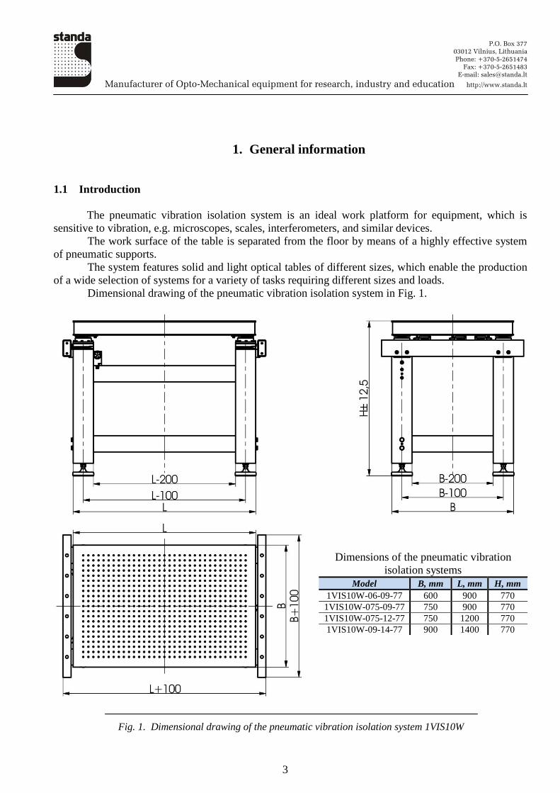
1. General information
1.1 Introduction
The pneumatic vibration isolation system is an ideal work platform for equipment, which is
sensitive to vibration, e.g. microscopes, scales, interferometers, and similar devices.
The work surface of the table is separated from the floor by means of a highly effective system
of pneumatic supports.
The system features solid and light optical tables of different sizes, which enable the production
of a wide selection of systems for a variety of tasks requiring different sizes and loads.
Dimensional drawing of the pneumatic vibration isolation system in Fig. 1.
Dimensions of the pneumatic vibration
isolation systems
Model B, mm L, mm H, mm
1VIS10W-06-09-77 600 900 770
1VIS10W-075-09-77 750 900 770
1VIS10W-075-12-77 750 1200 770
1VIS10W-09-14-77 900 1400 770
Fig. 1. Dimensional drawing of the pneumatic vibration isolation system 1VIS10W
P.O. Box 377
03012 Vilnius, Lithuania
Phone: +370-5-2651474
Fax: +370-5-2651483
E-mail: [email protected]
Manufacturer of Opto-Mechanical equipment for research, industry and education http://www.standa.lt
4
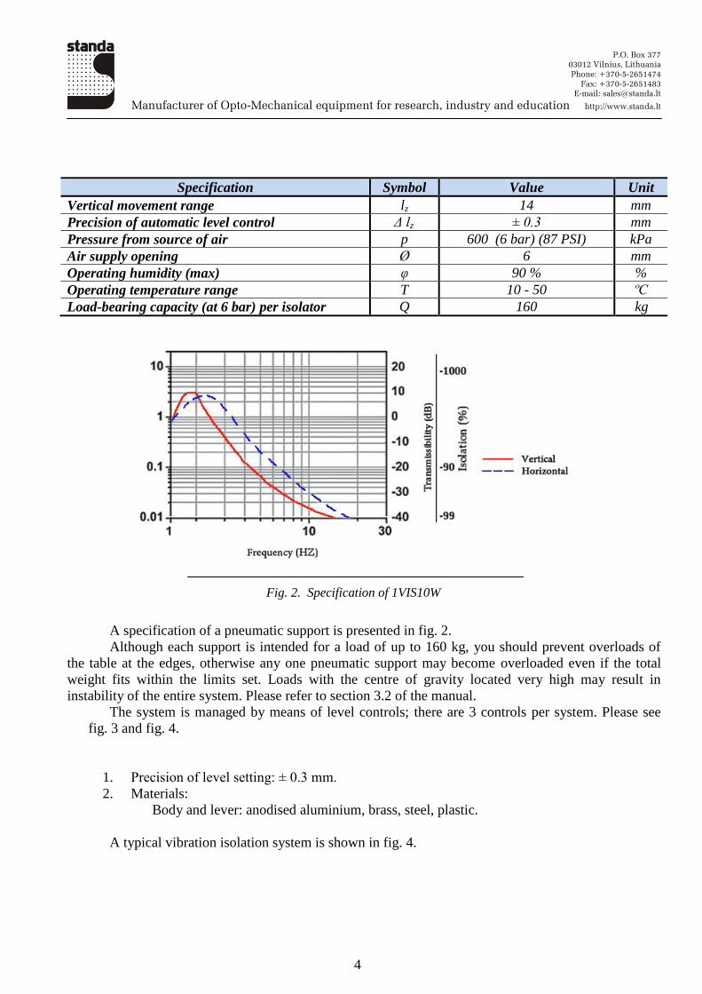
Specification Symbol Value Unit
Vertical movement range lz 14 mm
Precision of automatic level control Δ lz ± 0.3 mm
Pressure from source of air p 600 (6 bar) (87 PSI) kPa
Air supply opening Ø 6 mm
Operating humidity (max) φ 90 % %
Operating temperature range T 10 - 50 ºC
Load-bearing capacity (at 6 bar) per isolator Q 160 kg
Fig. 2. Specification of 1VIS10W
A specification of a pneumatic support is presented in fig. 2.
Although each support is intended for a load of up to 160 kg, you should prevent overloads of
the table at the edges, otherwise any one pneumatic support may become overloaded even if the total
weight fits within the limits set. Loads with the centre of gravity located very high may result in
instability of the entire system. Please refer to section 3.2 of the manual.
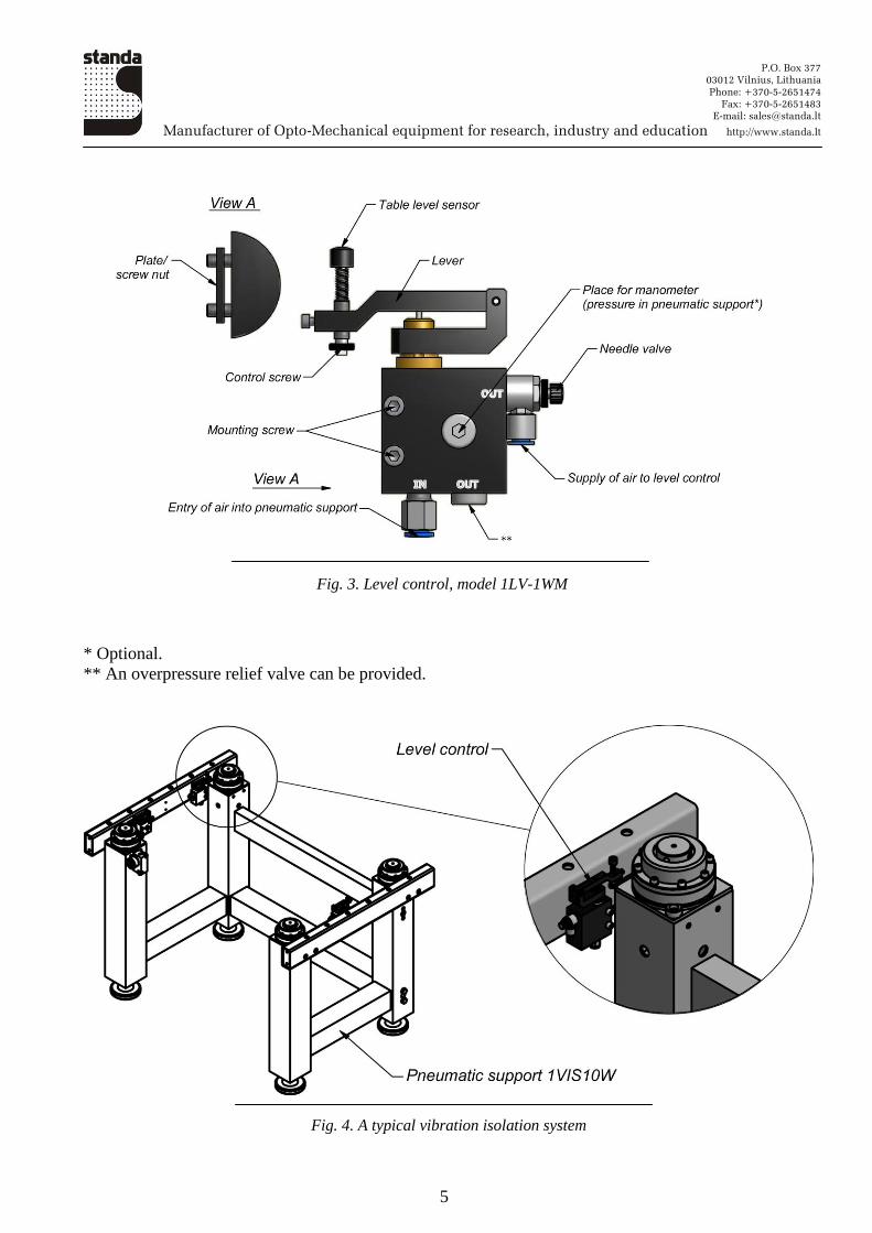
The system is managed by means of level controls; there are 3 controls per system. Please see
fig. 3 and fig. 4.
1. Precision of level setting: ± 0.3 mm.
2. Materials:
Body and lever: anodised aluminium, brass, steel, plastic.
A typical vibration isolation system is shown in fig. 4.
P.O. Box 377
03012 Vilnius, Lithuania
Phone: +370-5-2651474
Fax: +370-5-2651483
E-mail: [email protected]
Manufacturer of Opto-Mechanical equipment for research, industry and education http://www.standa.lt
5
Fig. 3. Level control, model 1LV-1WM
* Optional.
** An overpressure relief valve can be provided.
Fig. 4. A typical vibration isolation system
P.O. Box 377
03012 Vilnius, Lithuania
Phone: +370-5-2651474
Fax: +370-5-2651483
E-mail: [email protected]
Manufacturer of Opto-Mechanical equipment for research, industry and education http://www.standa.lt
6
1.1.1 Safety
This manual uses certain terms that are important for your safety.
Warning
Used to denote a danger that may result in injury.
Attention
Used to denote a situation that may result in damage to components of the system.
1.2 Location of the table
To ensure optimal operation of the system, it must be installed on a surface that satisfies certain
requirements.
The surface must be even.
It is important that an appropriate location for the system is chosen. The system must be installed
in the vicinity of bearing walls or columns, where the impact of low-frequency oscillation is smaller.
Furthermore, it is advisable to avoid placing the system in the vicinity of other sources of vibration such
as elevators, ventilation systems, industrial equipment, and airflows.
Warning
The system is a metal-made current conductor. If used together with electrical devices, the
table must be earthed.
1.3 Air supply requirements
The operation of the system requires a constant supply of air. After the system has been filled in
and set, air is used only for the operation of level controls when the load on the table changes.
Compressed air tanks (receivers) may be used for keeping the system operative. The air supply should be clean and dry for the best long-term results. The filtering degree must be at least
10 µm. The filter prevents impurities and water from entering the level controls, thus preventing them
from clogging.
The working pressure of the system is The required minimum working
pressure for the support with the maximum load may be computed using the following formula:
Where:
P means the required pressure in atm (bar).
Q means the load on the support with the maximum load including weight of the table top (kg).
Example:
Q = 100 kg
P.O. Box 377
03012 Vilnius, Lithuania
Phone: +370-5-2651474
Fax: +370-5-2651483
E-mail: [email protected]
Manufacturer of Opto-Mechanical equipment for research, industry and education http://www.standa.lt
7
The air supply system must be provided with a valve (plug) for a complete stoppage of air
supply in the case of maintenance and/or resetting of the system, or in cases of major changes in loads
of the system.
Attention
It is not advisable to use compressed carbon dioxide (CO2) tanks because rapid filling of
pneumatic supports may result in their icing up.
2. Mounting of the system
2.1 Assembly of the system
2.1.1 Safety
The weight of the optical table could reach 100 kg. For this reason, to prevent injuries during
assembly of the system, lifting mechanisms (a loader) and technological supports must be prepared in
advance.
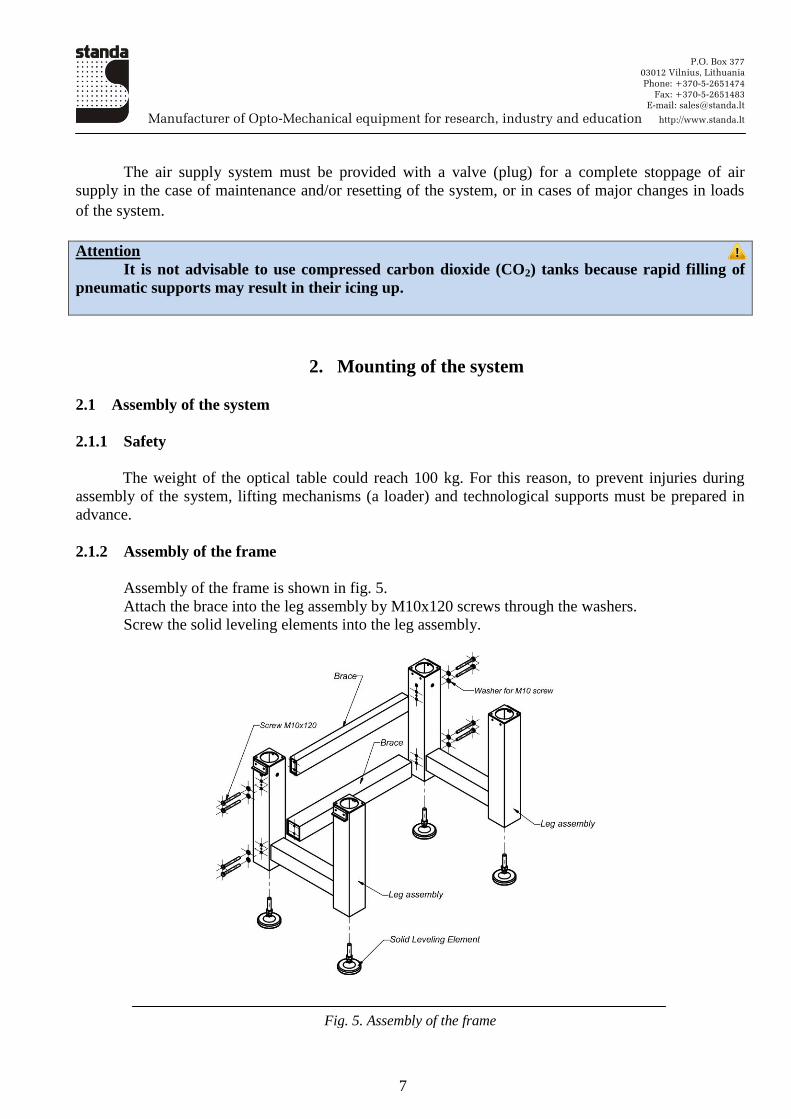
2.1.2 Assembly of the frame
Assembly of the frame is shown in fig. 5.
Attach the brace into the leg assembly by M10x120 screws through the washers.
Screw the solid leveling elements into the leg assembly.
Fig. 5. Assembly of the frame
P.O. Box 377
03012 Vilnius, Lithuania
Phone: +370-5-2651474
Fax: +370-5-2651483
E-mail: [email protected]
Manufacturer of Opto-Mechanical equipment for research, industry and education http://www.standa.lt
8
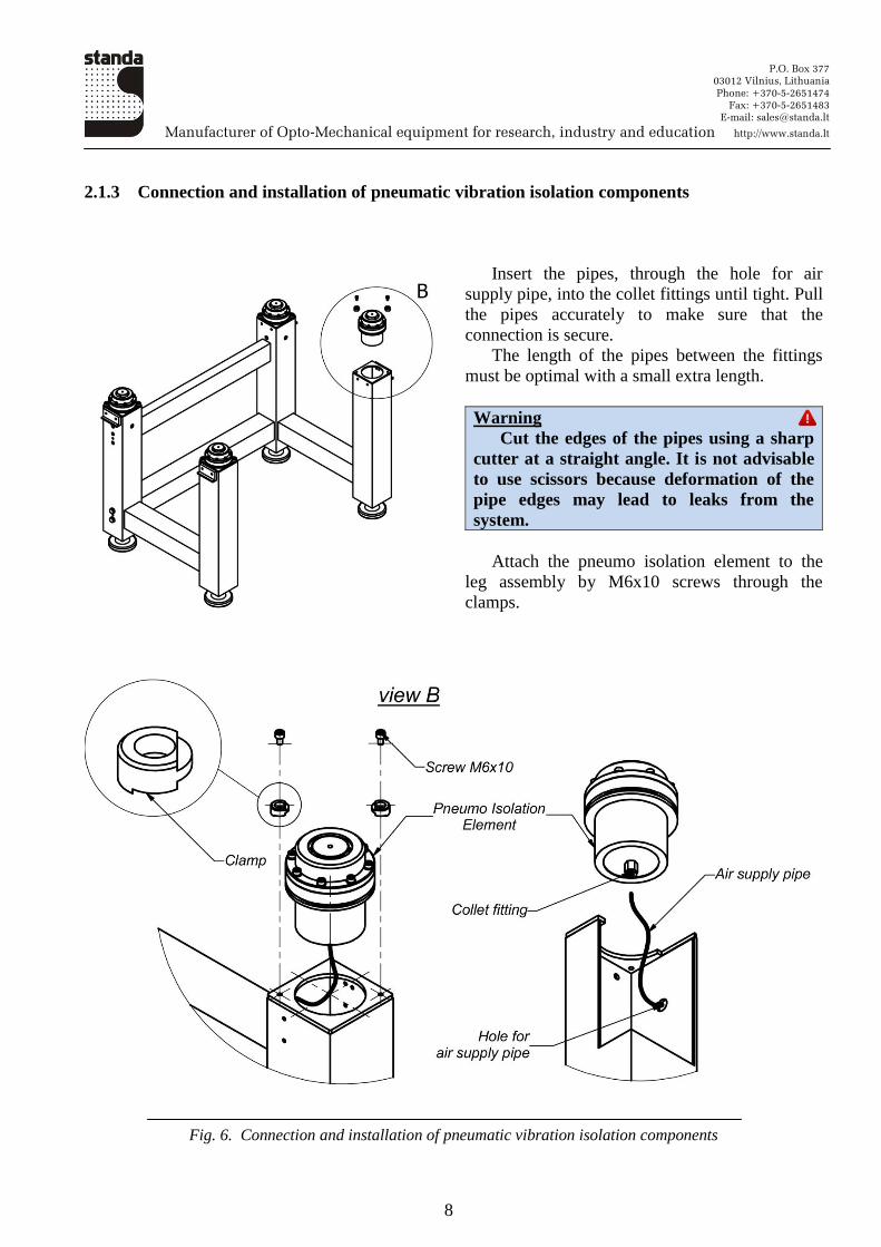
2.1.3 Connection and installation of pneumatic vibration isolation components
Insert the pipes, through the hole for air
supply pipe, into the collet fittings until tight. Pull
the pipes accurately to make sure that the
connection is secure.
The length of the pipes between the fittings
must be optimal with a small extra length.
Warning
Cut the edges of the pipes using a sharp
cutter at a straight angle. It is not advisable
to use scissors because deformation of the
pipe edges may lead to leaks from the
system.
Attach the pneumo isolation element to the
leg assembly by M6x10 screws through the
clamps.
Fig. 6. Connection and installation of pneumatic vibration isolation components
P.O. Box 377
03012 Vilnius, Lithuania
Phone: +370-5-2651474
Fax: +370-5-2651483
E-mail: [email protected]
Manufacturer of Opto-Mechanical equipment for research, industry and education http://www.standa.lt
9
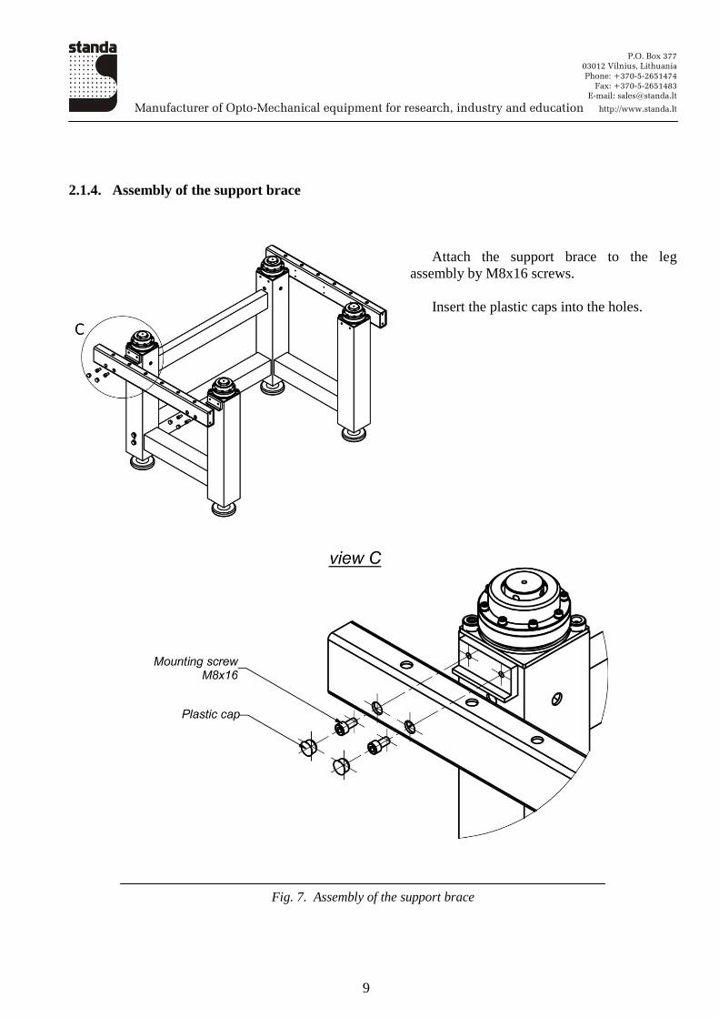
2.1.4. Assembly of the support brace
Attach the support brace to the leg
assembly by M8x16 screws.
Insert the plastic caps into the holes.
Fig. 7. Assembly of the support brace
P.O. Box 377
03012 Vilnius, Lithuania
Phone: +370-5-2651474
Fax: +370-5-2651483
E-mail: [email protected]
Manufacturer of Opto-Mechanical equipment for research, industry and education http://www.standa.lt
10
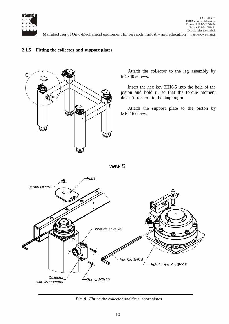
2.1.5 Fitting the collector and support plates
Attach the collector to the leg assembly by
M5x30 screws.
Insert the hex key 3HK-5 into the hole of the
piston and hold it, so that the torque moment
doesn’t transmit to the diaphragm.
Attach the support plate to the piston by
M6x16 screw.
Fig. 8. Fitting the collector and the support plates
P.O. Box 377
03012 Vilnius, Lithuania
Phone: +370-5-2651474
Fax: +370-5-2651483
E-mail: [email protected]
Manufacturer of Opto-Mechanical equipment for research, industry and education http://www.standa.lt
11
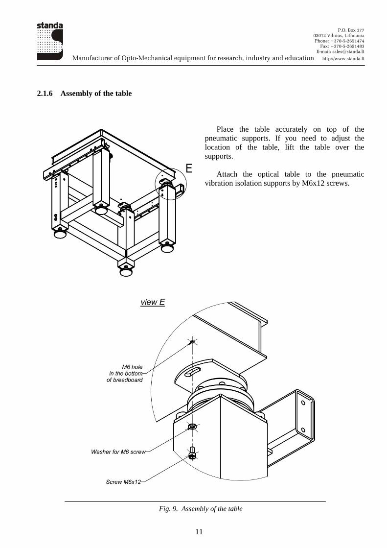
2.1.6 Assembly of the table
Place the table accurately on top of the
pneumatic supports. If you need to adjust the
location of the table, lift the table over the
supports.
Attach the optical table to the pneumatic
vibration isolation supports by M6x12 screws.
Fig. 9. Assembly of the table
P.O. Box 377
03012 Vilnius, Lithuania
Phone: +370-5-2651474
Fax: +370-5-2651483
E-mail: [email protected]
Manufacturer of Opto-Mechanical equipment for research, industry and education http://www.standa.lt
12
2.2 Preparation of the system for operation and vibration isolation of the table
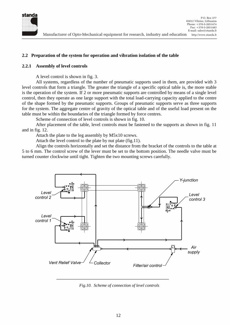
2.2.1 Assembly of level controls
A level control is shown in fig. 3.
All systems, regardless of the number of pneumatic supports used in them, are provided with 3
level controls that form a triangle. The greater the triangle of a specific optical table is, the more stable
is the operation of the system. If 2 or more pneumatic supports are controlled by means of a single level
control, then they operate as one large support with the total load-carrying capacity applied to the centre
of the shape formed by the pneumatic supports. Groups of pneumatic supports serve as three supports
for the system. The aggregate centre of gravity of the optical table and of the useful load present on the
table must be within the boundaries of the triangle formed by force centres.
Scheme of connection of level controls is shown in fig. 10.
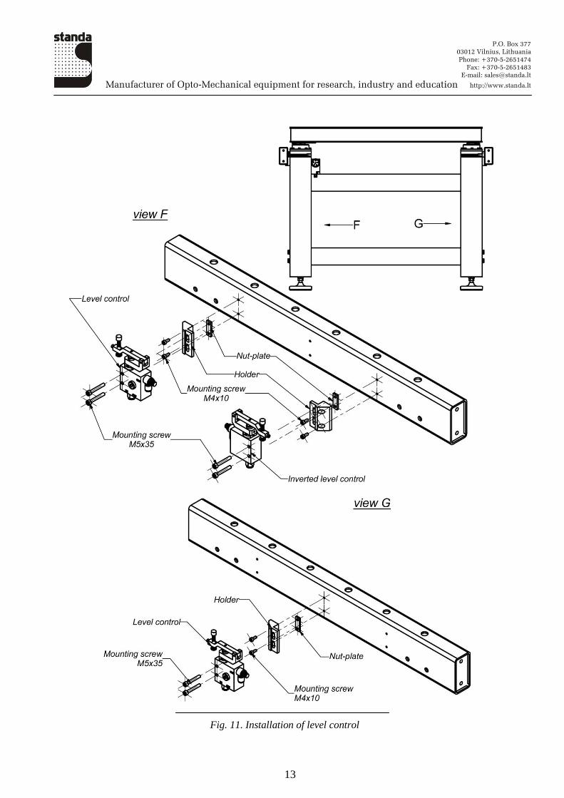
After placement of the table, level controls must be fastened to the supports as shown in fig. 11
and in fig. 12.
Attach the plate to the leg assembly by M5x10 screws.
Attach the level control to the plate by nut plate (fig.11).
Align the controls horizontally and set the distance from the bracket of the controls to the table at
5 to 6 mm. The control screw of the lever must be set to the bottom position. The needle valve must be
turned counter clockwise until tight. Tighten the two mounting screws carefully.
Fig.10. Scheme of connection of level controls
P.O. Box 377
03012 Vilnius, Lithuania
Phone: +370-5-2651474
Fax: +370-5-2651483
E-mail: [email protected]
Manufacturer of Opto-Mechanical equipment for research, industry and education http://www.standa.lt
13
Fig. 11. Installation of level control
P.O. Box 377
03012 Vilnius, Lithuania
Phone: +370-5-2651474
Fax: +370-5-2651483
E-mail: [email protected]
Manufacturer of Opto-Mechanical equipment for research, industry and education http://www.standa.lt
14
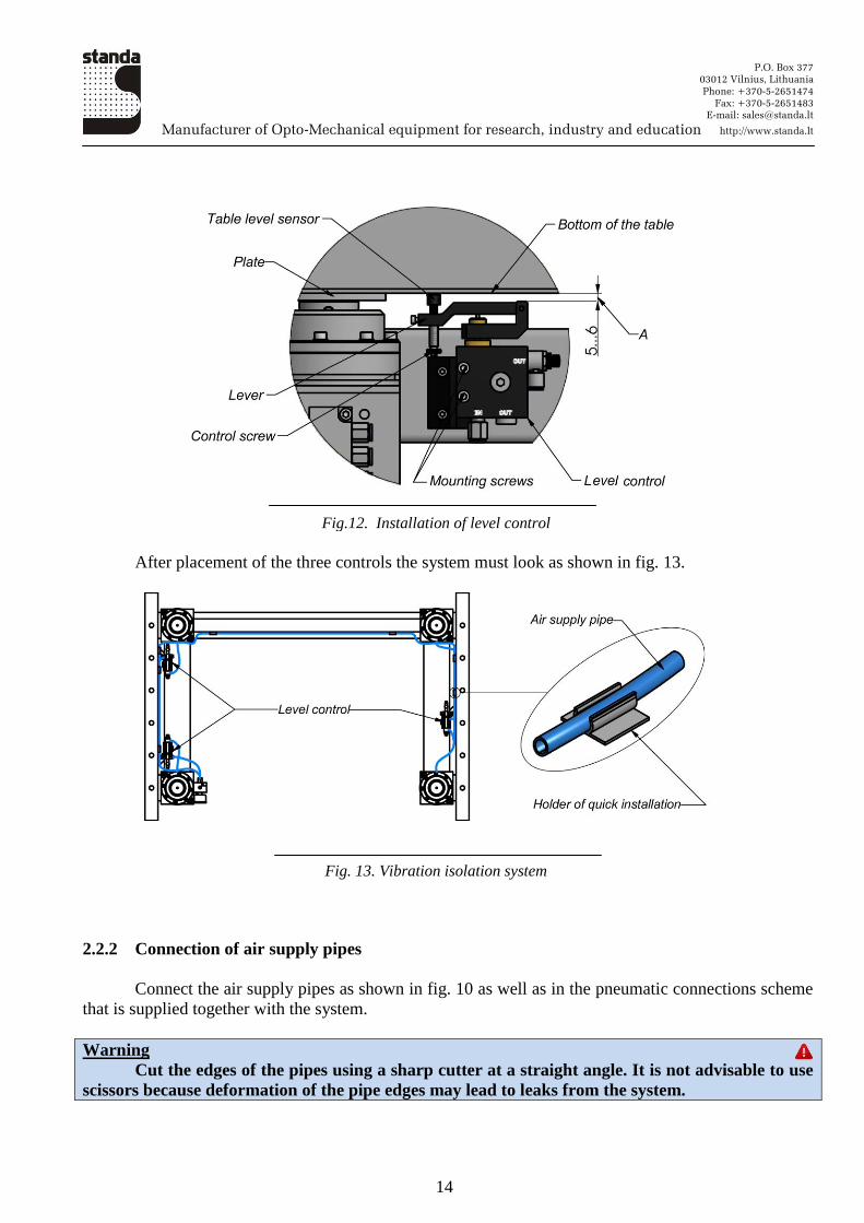
Fig.12. Installation of level control
After placement of the three controls the system must look as shown in fig. 13.
Fig. 13. Vibration isolation system
2.2.2 Connection of air supply pipes
Connect the air supply pipes as shown in fig. 10 as well as in the pneumatic connections scheme
that is supplied together with the system.
Warning
Cut the edges of the pipes using a sharp cutter at a straight angle. It is not advisable to use
scissors because deformation of the pipe edges may lead to leaks from the system.
P.O. Box 377
03012 Vilnius, Lithuania
Phone: +370-5-2651474
Fax: +370-5-2651483
E-mail: [email protected]
Manufacturer of Opto-Mechanical equipment for research, industry and education http://www.standa.lt
15
Insert the pipes in the collet fittings until tight. Pull the pipes accurately to make sure that the
connection is secure.
The length of the pipes between the fittings must be optimal with a small extra length.
Place the tubes along the braces system and secure them with holders of quick installation (fig.
13)
Connect the air supply and set the pressure control based on the computation of its value carried
out in advance according to the formula provided in section 1.3.
Attention
The pressure in the system may not exceed 6 bar.
Check all accessible connections for possible leaks. Eliminate any leaks established prior to
starting further operation.
If the table does not start to float in a few minutes, increase the air pressure, check whether the
needle valve is open and try to adjust the position of the control lever by turning the control screw
clockwise.
Note
If the table starts oscillating after emerging, decrease the air pressure in the system and adjust the
needle valves by turning them clockwise.
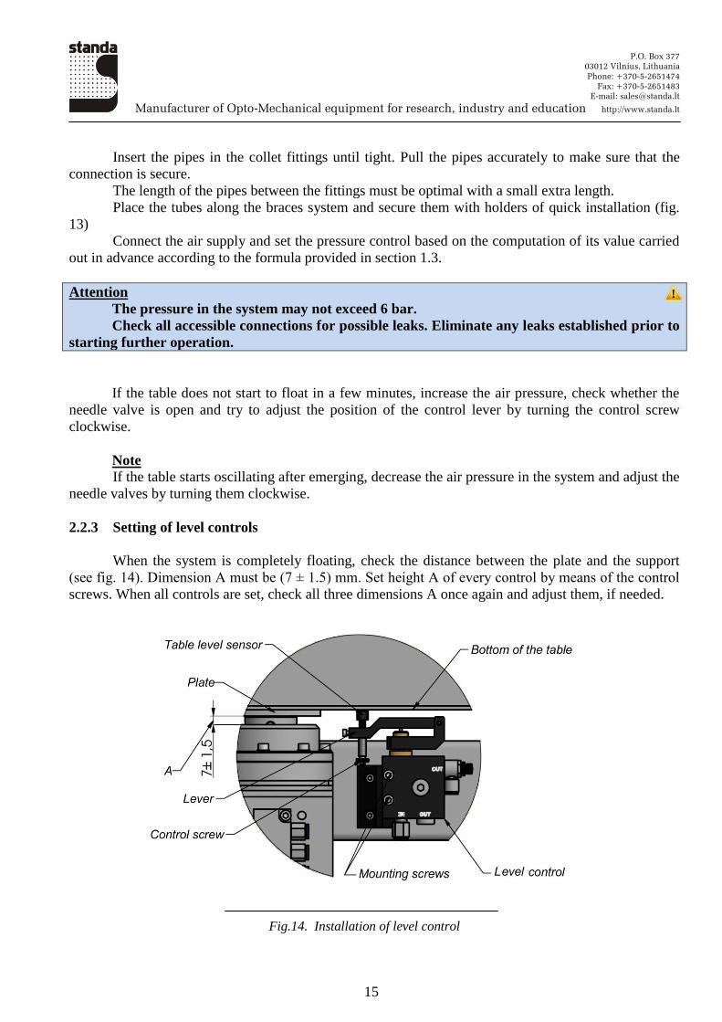
2.2.3 Setting of level controls
When the system is completely floating, check the distance between the plate and the support
(see fig. 14). Dimension A must be (7 ± 1.5) mm. Set height A of every control by means of the control
screws. When all controls are set, check all three dimensions A once again and adjust them, if needed.
Fig.14. Installation of level control
P.O. Box 377
03012 Vilnius, Lithuania
Phone: +370-5-2651474
Fax: +370-5-2651483
E-mail: [email protected]
Manufacturer of Opto-Mechanical equipment for research, industry and education http://www.standa.lt
16
Make sure that the table is floating freely on the supports. Move the table accurately from side to
side by approximately 3 mm. Perform the same operation by moving the table up and down by the same
distance. The moving of the table must be unimpeded and must not produce any noises.
Press each of the angles of the table one after another for approximately 3 mm and then release
the pressure. The table must return to the original position in approximately 3 to 4 seconds. Adjust if
necessary by means of the needle valves and pressure in the system.
3. Management of the system
3.1 Main principles
After completing the assembly of the system and once the table has emerged, minor changes
may be introduced based on individual requirements for the system. These adjustments include
parameters such as air pressure in the system, position of the level control lever, and setting of the
needle valve.
Warning
After the table has emerged, the space between the table and the support may become a
zone of danger.
Any object present in this zone may be squeezed in the case of changes in the load on the
table or in the pressure, which can result in injuries.
3.2 Adjustment of parameters of the system
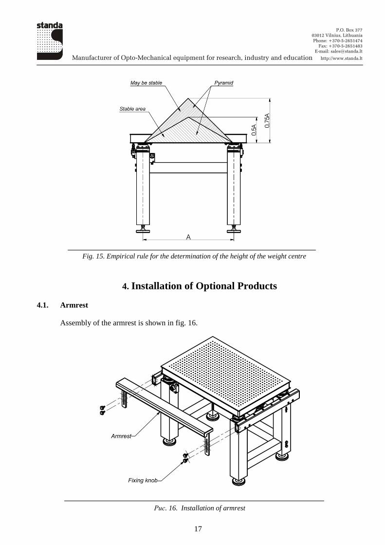
If a load has a high weight centre, the table may start to oscillate. In this case, you need to reduce
the pressure in the system and close the needle valve. This will improve the stability of the table. The
empirical rule to determine the height of the weight centre is shown in fig. 15. The system can be in
three different modes – stable, may be stable and unstable, depending on the position of the weight
centre. If the overall weight centre is outside of stable and may be stable areas, the system will lack
stability.
3.3 Maintenance
If operated correctly, the pneumatic vibration isolation system needs minimum maintenance. As
a rule, the maintenance includes the assurance of the cleanliness of the air supplied, i.e. replacement of
the filter and removal of any water.
3.3.1 Cleaning
The table and other parts of the system may be cleaned using a non-abrasive liquid detergent.
3.3.2 Air quality
Oil, water or impurities contained in the air entering the system may clog level controls and
worsen the operation of the system. Use of air treatment filters is obligatory. Please refer to section 1.3.
P.O. Box 377
03012 Vilnius, Lithuania
Phone: +370-5-2651474
Fax: +370-5-2651483
E-mail: [email protected]
Manufacturer of Opto-Mechanical equipment for research, industry and education http://www.standa.lt
17
Fig. 15. Empirical rule for the determination of the height of the weight centre
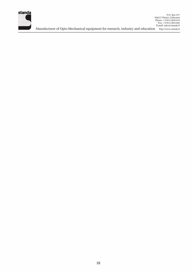
4. Installation of Optional Products
4.1. Armrest
Assembly of the armrest is shown in fig. 16.
Рис. 16. Installation of armrest
P.O. Box 377
03012 Vilnius, Lithuania
Phone: +370-5-2651474
Fax: +370-5-2651483
E-mail: [email protected]
Manufacturer of Opto-Mechanical equipment for research, industry and education http://www.standa.lt
18