vibration limit switch lvl-m2
TRANSCRIPT

Vibration Limit SwitchLVL-M2< Limit switch for liquids< Large selection of process connections: universal use< Wide variety of electronic modules (e. g., relay, thyristor signal
output): the right connection for every process control system< No calibration: quick and low-cost start up< No mechanically moving parts: maintenance-free, no wear, long
operating life< Monitoring of the vibrating fork for damage: guaranteed function< PROFIBUS PA protocol: commissioning and maintenance quick
and easy< Up to SIL 2 acc. to IEC 61508
2 Function
The device is a level limit switch for use in all liquids.l for temperature from -50 °C to +150 °Cl for pressures up to 64 barl for viscosities up to 10000 mm2/sl for densities up to 0.5 g/cm3 or 0.7 g/cm3 (other settings available on request)The function is not affected by flow, turbulence, bubbles, foam, vibration, bulk solids content or build-up, the device is thus the ideal substitute forfloat switches.The device is available with extension tube up to 3 m (up to 6 m on request).High corrosion-resistant Alloy C4 (2.4610) is available for the vibration fork and process connection for applications in very aggressive liquids.Devices with protection Ex ia and Ex d are available for use in explosion hazardous areas.
Connection
Connection FEL 52 (E5) 3-wire DC connection (example)
e. g.
relay
PLC
- preferably for use with memory
programmable controls (PLC)
- positive signal at the switch output
of the electronics (PNP)
- Output blocked on reaching limit
level.
- also in compact housing with
plug connection available
Other connection types see section
electrical connection.
L+
1
L–
2 3
(+)
–
FEL 52 (E5)
...U – 10 V DC ... 55 V DC
1
Rele
ase
date
:20
21-0
4--
13 D
ate
of
Rele
ase
date
: 202
1-04
-13
Dat
e of
issu
e: 2
021-
04-1
3 Fi
lena
me:
270
755_
eng.
Germany: +49 621 776 2222Pepperl+Fuchs Group
Refer to "General Notes Relating to Pepperl+Fuchs Product Information".
USA: +1 330 486 0002 Singapore: +65 6779 9091www.pepperl-fuchs.com [email protected] [email protected]@de.pepperl-fuchs.com

Dimensions
10
L
Ø80
L
~2
5
Ø85
ma
x. 1
73
max
. 40.
7
max. 60
max. 65
ma
x. 1
55
max. 76
17.5
Ø21.5
Additional dimensions see
section dimensions.
Length L see process connection.
Device with aluminium
housing A* and process
connection with flange
Device with polyester
housing P* and process
connection G**
Technical Data
General specificationsFunction principle limit detection
Maximum or minimum detection in tanks or pipelines containing all types of liquidsincluding use in explosion hazardous areas. Particularly suited to very aggressiveliquids thanks to high degree of corrosion protection.
Measuring method The forks of the sensors vibrate at their intrinsic frequency. This frequency is reducedwhen covered with liquid.The change in frequency then activates the limit switch.
Construction type device with extension tubeSeries Vibracon LVL-M2
SupplyRated voltage Ur electronic insert FEL50A (PA): 9 ... 32 V DC
electronic insert FEL51 (AC): 253 V AC, 50/60 Hzelectronic insert FEL52 (E5): 10 ... 55 V DCelectronic insert FEL54 (WA): 19 ... 253 V AC, 50/60 Hz or 19 ... 55 V DCelectronic insert FEL55 (SI): 11 ... 36 V DC, PLCelectronic insert FEL56 (N1), FEL58 (N2): isolating amplifier acc. to EN 60947-5-6(NAMUR)
Current consumption electronic insert FEL52 (E5): max. 15 mAPower consumption electronic insert FEL52 (E5): max. 0.83 W
electronic insert FEL54 (WA): max. 1.3 WElectrical specifications
Surge protection electronic insert FEL51 (AC), electronic insert FEL52 (E5), electronic insert FEL54(WA), electronic insert FEL55 (SI): overvoltage category III
InputSwitching point see section switch pointMeasured variable limit level (limit value)
Vibration Limit Switch LVL-M2Re
leas
e da
te: 2
021-
04-1
3 D
ate
of is
sue:
202
1-04
-13
File
nam
e: 2
7075
5_en
g.pd
f
2Germany: +49 621 776 2222Pepperl+Fuchs Group
Refer to "General Notes Relating to Pepperl+Fuchs Product Information".
USA: +1 330 486 0002 Singapore: +65 6779 9091www.pepperl-fuchs.com [email protected] [email protected]@de.pepperl-fuchs.com

Technical Data
Measurement range depends on mounting pointOutput
Switching delay when fork is covered: approx. 0.5 s, when fork is exposed: approx. 1.0 s (otherswitching times on request)additionally configurable for PROFIBUS PA (electronic insert FEL50A (PA)): 0.5 ... 60s
Switch behaviour switch-over for minimum/maximum residual current safety on electronic insertMAX = maximum safety:The output switches to the power fail response when the fork is covered.for use with overspill protection for exampleMIN = minimum safety:The output switches to the power fail response when the fork is exposed.for use with dry running protection for exampleWhen switching on the power supply the output assumes the alarm signal. After max.2 s it assumes the correct switching mode.
Directive conformityElectromagnetic compatibility
Directive 89/336/EEC EN 61326If the fork tines are joined together on account of build-up, the useful signal isattenuated to such an extent that the original EMC values can no longer be completelyobserved (EN 61000-4-3 electromagnetic fields,EN 61000-4-6 HF coupling).
Low voltageDirective 73/23/EEC EN 61010-1
ConformityElectromagnetic compatibility NE 21Degree of protection IEC 60529Vibration resistance EN 60068-2-6Climate class DIN EN 60068-2-38/IEC 68-2-38
Input characteristicsMedium density adjustment on the electronic insert > 0,5 g/cm3 or > 0,7 g/cm3 (other on request)
Measurement accuracyReference operating conditions ambient temperature: 23 °C (73.4 °F), medium temperature: 23 °C (73.4 °F),
product density: 1 g/cm3 (water), viscosity: 1 mm2/s, medium pressure pe: 0 bar,sensor mounting: vertical from above, density switch: to > 0.7 g/cm3
Maximum measured error max. ± 1 mm, specified by mounting positionNon-repeatability 0.1 mmHysteresis approx. 2 mmInfluence of medium density max. +4.8 ... -3.5 mm (0.5 ... 1.5 g/cm3)Influence of medium temperature max. +1.4 ... -2.8 mm (-40 ... 150 °C (-40 ... 302 °F))Influence of medium pressure max. 0 ... -2.5 mm (-1 ... 64 bar)
Operating conditionsInstallation conditions
Installation position with short pipe (up to 500 mm (19.7 inch)) any position, with long pipe verticalProcess conditions
Medium temperature -50 ... 150 °C (-58 ... 302 °F) , exceptions see process connectionsMedium pressure pe = -1 ... 64 bar (-14.5 ... 928.3 psi) over the entire temperature range , exceptions see
process connectionsTest pressure max. 100 bar (1.5 times the medium pressure pe), no function during test pressure,
burst pressure of diaphragm 200 barThermal shock resistance max. 120 °C/s (max. 120 K/s)State of aggregation liquidDensity min. 0.5 g/cm3 (compact housing 0.7 g/cm3), other density settings on requestViscosity max. 10000 mm2/s (max. 10000 cSt)Solid contents < ∅5 mm
Ambient conditionsAmbient temperature -50 ... 70 °C (-58 ... 158 °F) , function with reduced data values
see section ambient temperatureStorage temperature -50 ... 80 °C (-58 ... 176 °F)Vibration resistance 10 ... 50 Hz, 0.15 mm, 100 cycles
Mechanical specifications
Vibration Limit Switch LVL-M2Re
leas
e da
te: 2
021-
04-1
3 D
ate
of is
sue:
202
1-04
-13
File
nam
e: 2
7075
5_en
g.pd
f
3Germany: +49 621 776 2222Pepperl+Fuchs Group
Refer to "General Notes Relating to Pepperl+Fuchs Product Information".
USA: +1 330 486 0002 Singapore: +65 6779 9091www.pepperl-fuchs.com [email protected] [email protected]@de.pepperl-fuchs.com

Technical Data
Degree of protection polyester, steel, and aluminum housing: IP66/IP67compact housing:- IP65 with valve connector PG11 or 1/2NPT- IP66/IP68 with M12 x 1 connector without LEDs (1.4435/316L)- IP69K with M12 x 1 connector with LEDs (1.4435/316L)
Connection electronic inserts: cross section max. 2.5 mm2, lace in end splice in acc. with DIN46228ground lead in housing: cross section max. 2.5 mm2
external equipotential bonding: cross section 4 mm2
Material wetted parts:- process connection and extension tube: 1.4435/316L or 2.4610/Alloy C4- vibration fork: 1.4435/316L or 2.4610/Alloy C4- flat seal for process connection G2* or G3*: elastomer fibre, asbestos-freehousings:- polyester housing: PBT-FR with PBT-FR cover or with PA12 cover with sight glass,cover seal: EPDM- stainless steel housing: 1.4435/316L, cover seal: silicone- aluminum housing: EN-AC-AlSi10Mg, plastic-coated, cover seal: EPDM- compact housing with valve connector or M12 connector: 1.4435/316Lcable gland: polyamide or brass, nickel-platedtemperature spacer: 1.4435/316Lflameproof bushing: 1.4435/316L
Surface quality Ra < 3.2 µm/80 grit: length, spacer, bushings *A, *B, *EMass 600 g , basic weight: compact sensor, electronic insert, stainless steel housing,
process connection G2*, additional weight is dependent on housing and processconnectionprocess connections:- A31 1000 g, A4* 1200 g, A5* 1500 g, A6* 2400 g, A72 4800 g, A81 4900 g, A82 6800g, A91 7000 g, A92 11,5 kg, A93 17,3 kg- - C45 1400 g, C51 1200 g, C71 1600 g, C75 3200 g, C95 5900 g, CA3 5600 g- D45 1400 g, D51 1200 g, D71 1600 g, D75 3200 g, D95 5900 g, DA3 5600 g- F45 1400 g, F51 1200 g, F55 2000 g, F61 1400 g, F65 2400 g, F71 1600 g, F75 3200g, F7F 2600 g, F81 2400 g, F85 4300 g, F93 4800 g, F95 5900 g, FA3 5600 g, FA5 7500 g- G3* 200 g- J13 no information, J16 no information, J17 1700 g, J19 no information, J1A noinformation, J1C 1700 g- N3* 200 g, N75 2900 g- R3* 200 g- T51 no information, T61 100 gextension tube, tempeprature spacers, flameproof bushings:- B* 900 g/m, C* 2300 g/100 inch- D* 100 g- J* 900 g/m and 600 g, K* 2300 g/100 inch and 600 g- L* 700 g- R* 900 g/m and 700 g, S* 2300 g/100 inch and 700 g- T* 800 g
Dimensions housing: diameter max. 85 mm, height max. 173 mmtemperature separator, flameproof bushing: additional length L 140 mmprocess connection: length L 66.5 ... 80 mmextension: length type II, for vertical installation from above same switching point asVibracon LVL1, LVL2vibration fork: width 17.5 mm, fork width 10 mm, length 25 mm
Process connection - cylindrical thread G3/4A, G1A to DIN ISO 228/1 with flat seal to DIN 7603- conical thread R3/4, R1 to DIN 2999, part 1- conical thread 3/4NPT, 1NPT to ANSI B 1.20.1- flush-mounted with welding sleeve to factory standard (G3/4A, G1A)- Triclamp 1-1/2 inch, 2 inch to ISO 2852- flanges to EN 1092-1 from DN25, to ANSI B 16.5 from 1 inch, to JIS B 2238 (RF) fromDN25For further information see type code.
Data for application in connection with hazardous areasEU-type examination certificate see instruction manuals (SI)
International approvalsFM approval see control drawings (ZD)CSA approval see control drawings (ZD)IECEx approval see instruction manuals (SI)
Indication and operation
Vibration Limit Switch LVL-M2Re
leas
e da
te: 2
021-
04-1
3 D
ate
of is
sue:
202
1-04
-13
File
nam
e: 2
7075
5_en
g.pd
f
4Germany: +49 621 776 2222Pepperl+Fuchs Group
Refer to "General Notes Relating to Pepperl+Fuchs Product Information".
USA: +1 330 486 0002 Singapore: +65 6779 9091www.pepperl-fuchs.com [email protected] [email protected]@de.pepperl-fuchs.com

Technical Data
Display elements electronic inserts:- electronic inserts FEL50 A (PA), FEL58 (N2): green LED, yellow LED- electronic inserts FEL51 (AC), FEL52 (E5), FEL54 (WA), FEL55 (SI), FEL56 (N1):green LED, red LEDcompact housings:compact housing with valve connector- electronic version FEL51 (AC), FEL52 (E5): green LED, red LED- electronic version FEL58 (N2): green LED, yellow LEDcompact housing with M12 x 1 round connector without LEDs- electronic version FEL52 (E5): green LED, yellow LED, red LED- electronic version FEL58 (N2): green LED, yellow LEDcompact housing with M12 x 1 round connector with LEDs- electronic version FEL52 (E5): green LED, two yellow LEDs
Control elements electronic insert FEL50A (PA): 8 switches for device address settingelectronic inserts FEL51 (AC), FEL52 (E5), FEL54 (WA), FEL55 (SI), FEL56 (N1): twoswitches for fail-safe mode and density changeelectronic insert FEL58 (N2): two switches for fail-safe mode and density change andone test button interrupts lead
Function test compact housing: function test with test magnetelectronic versions FEL51 (AC), FEL52 (E5) and FEL58 (N2): During the test, thecurrent state of the electronic switch is reversed.
Certificates and approvalsSIL classification up to SIL2 acc. to IEC 61508Overspill protection see approval (ZE)
General informationSupplementary documentation technical information (TI)
manuals, brief instructions (BA, KA)instruction manuals (SI)control drawings (ZD)
Supplementary information Observe the certificates, declarations of conformity, instruction manuals, and manualswhere applicable. For information see www.pepperl-fuchs.com.
AccessoriesDesignation see technical information (TI)
Accessories
PACTware 5.X FDT Framework
DTM Level Control
Vibration Limit Switch LVL-M2Re
leas
e da
te: 2
021-
04-1
3 D
ate
of is
sue:
202
1-04
-13
File
nam
e: 2
7075
5_en
g.pd
f
5Germany: +49 621 776 2222Pepperl+Fuchs Group
Refer to "General Notes Relating to Pepperl+Fuchs Product Information".
USA: +1 330 486 0002 Singapore: +65 6779 9091www.pepperl-fuchs.com [email protected] [email protected]@de.pepperl-fuchs.com

Relea
se da
te: 20
21-04
-13 D
ate of
issu
e: 20
21-04
-13 F
ilena
me: 2
7075
5_en
g.pdf
LVL-M2
6Germany: +49 621 776 2222Pepperl+Fuchs GroupRefer to "General Notes Relating to Pepperl+Fuchs Product Information".
USA: +1 330 486 0002 Singapore: +65 6779 9091www.pepperl-fuchs.com [email protected] [email protected]@de.pepperl-fuchs.com
Vibration Limit Switch
DimensionsCompact housing C*
Stainless steel housing E*
Process connections
4030
133
199
141
L20
6
Ø40 Ø40
32 32
Ø76 max. 64
max.
150
L
L see porcess connections
8061
.341
(66.5
)50
.5
32
66.5 66
.550
.5
32 41
6950
.5
(69)
50.5
41
(66.5
)50
.5
32
(69)
50.5
4166
.5
A**, C**, D**, F**, J**, N75 G2* G3* G3E
N2* N3* R2* R3* T**

Relea
se da
te: 20
21-04
-13 D
ate of
issu
e: 20
21-04
-13 F
ilena
me: 2
7075
5_en
g.pdf
LVL-M2
7Germany: +49 621 776 2222Pepperl+Fuchs GroupRefer to "General Notes Relating to Pepperl+Fuchs Product Information".
USA: +1 330 486 0002 Singapore: +65 6779 9091www.pepperl-fuchs.com [email protected] [email protected]@de.pepperl-fuchs.com
Vibration Limit SwitchExtension tube
Vibration fork
Connection
L
Ø21.5 L Ø21.5
Thread: G3/4AG1A
Flanges and flange-likeprocess connections
from seal surface ofthread adapter
L Ø21.5
Thread: 3/4NPT1NPTR3/4R1
from lower edgeof thread
L = 148 mm ... 3000 mm up to 6000 mm on request
Ø21.5
10
max.
40.7
~25
17.5

Relea
se da
te: 20
21-04
-13 D
ate of
issu
e: 20
21-04
-13 F
ilena
me: 2
7075
5_en
g.pdf
LVL-M2
8Germany: +49 621 776 2222Pepperl+Fuchs GroupRefer to "General Notes Relating to Pepperl+Fuchs Product Information".
USA: +1 330 486 0002 Singapore: +65 6779 9091www.pepperl-fuchs.com [email protected] [email protected]@de.pepperl-fuchs.com
Vibration Limit SwitchElectronic insert FEL50A (PA)2-wire connection for power supply and data transfer for connecting to PROFIBUS PA
Additional functions:• Digital communication enables the representation, reading and
editing of the following parameters: fork frequency, switch-on frequency, switch-off frequency, switch-on time and switch-off time, status, measured value, density switch.
• Matrix locking possible.• Switch to WHG mode possible (WHG approval).• You can also visit www.profibus.com for more information.
Electronic insert FEL51 (AC)2-wire AC connectionAlways connect in series with a load!
Check the following:• the residual current in blocked state (up to 3.8 mA)• that for low voltage
– The voltage drop across the load is such that the minimum terminal voltage at the electronic insert (19 V) when blocked is not undershot.
– The voltage drop across the electronics when switched through is observed (up to 12 V).
• that a relay cannot de-energise with holding power below 3.8 mAIf this is the case, a resistor should be connected parallel to the relay (RC module available on request).
• When selecting the relay, pay attention to the holding power/rated power (see connectable load).
PA- PA+
FEL50A (PA)
U– 9 V DC ... 32 V DC
PROFIBUS PA
EX
EX–
–
–
–
…
Segment coupler
L1
1
N N PE
2
1A
FEL51 (AC)
U~ max. 253 V AC, 50/60 Hz
externalload
19 Vmin.

Relea
se da
te: 20
21-04
-13 D
ate of
issu
e: 20
21-04
-13 F
ilena
me: 2
7075
5_en
g.pdf
LVL-M2
9Germany: +49 621 776 2222Pepperl+Fuchs GroupRefer to "General Notes Relating to Pepperl+Fuchs Product Information".
USA: +1 330 486 0002 Singapore: +65 6779 9091www.pepperl-fuchs.com [email protected] [email protected]@de.pepperl-fuchs.com
Vibration Limit SwitchElectronic FEL51 (AC) in compact housing
Electronic insert FEL52 (E5)3-wire DC connection• preferably used with programmable
logic controllers (PLC), DI module as per EN 61131-2.• positive signal at switching output of the electronics (PNP)• Output blocked on reaching limit.
Electronic FEL52 (E5) in compact housing
MAX MIN
1
3
1 2
R
L1 NPE
> 19 V
R
L1 NPE
> 19 V
(Ground) (Ground)
Housing C2 (½ NPT)orHousing C6 (PG11)
Connection
1.0 A 1.0 A 1 A 1 A
1 2 3
L+
U– 10 V DC … 55 V DC
L–
(+)
–
FEL52 (E5)
…
e. g.relayPLC
0.5 A
Housing C2 (½ NPT)orHousing C6 (PG11)
Housing C4 (M12 x 1),connector without LEDs
Housing C4 (M12 x 1),connector with LEDs
Connection
(Ground) (Ground)
0.5 A 0.5 A
0.5 A 0.5 A
MAX MIN
L– L–L+ L+PE PE
+
–R
33
22 11
+
–R
L– L+
R
L– L+
2(WT)
1(BN)
3(BU)
4(BK)
2(WT)
1(BN)
3(BU)
4(BK)
R

Relea
se da
te: 20
21-04
-13 D
ate of
issu
e: 20
21-04
-13 F
ilena
me: 2
7075
5_en
g.pdf
LVL-M2
10Germany: +49 621 776 2222Pepperl+Fuchs GroupRefer to "General Notes Relating to Pepperl+Fuchs Product Information".
USA: +1 330 486 0002 Singapore: +65 6779 9091www.pepperl-fuchs.com [email protected] [email protected]@de.pepperl-fuchs.com
Vibration Limit SwitchElectronic insert FEL54 (WA)Universal current connection with relay output• Power supply:
Please note the different voltage ranges for AC and DC.• Output:
When connecting an instrument with high inductance, provide a spark arrester to protect the relay contact.A fine-wire fuse (depending on the load connected) protects the relay contact on short-circuiting.Both relay contacts switch simultaneously.
* When jumpered, the relay output works with NPN logic.
Electronic insert FEL55 (SI)2-wire connection for separate switching unit• for connecting to programmable logic controllers (PLC) for
example, AI module 4 mA ... 20 mA to EN 61131-2• Output signal jump from high to low current on limit (H-L edge)
0,5 A
1 3 4 5 6 7 82
FEL54 (WA)
L1L+
U~ 19 V AC … 253 V AC, 50/60 HzU– 19 V DC … 55 V DC
NL–
PE a u r a u r
*
1 2
FEL55 (SI)
–
EEx ia
+
EX
EXI
U– 11 V DC … 36 V DCe. g. PLC
…

Relea
se da
te: 20
21-04
-13 D
ate of
issu
e: 20
21-04
-13 F
ilena
me: 2
7075
5_en
g.pdf
LVL-M2
11Germany: +49 621 776 2222Pepperl+Fuchs GroupRefer to "General Notes Relating to Pepperl+Fuchs Product Information".
USA: +1 330 486 0002 Singapore: +65 6779 9091www.pepperl-fuchs.com [email protected] [email protected]@de.pepperl-fuchs.com
Vibration Limit SwitchElectronic insert FEL56 (N1)2-wire connection for separate switching unit• for connecting to switch amplifiers acc. to NAMUR
(IEC 60947-5-6), e. g. switch amplifiers from Pepperl+Fuchs• Output signal jump from low to high current on limit (L-H edge)
Connecting to multiplexer: set clock time to min. 2 s.
Electronic insert FEL58 (N2)2-wire connection for separate switching unit• for connecting to switch amplifiers acc. to NAMUR
(IEC 60947-5-6), e. g. switch amplifiers from Pepperl+Fuchs• Output signal jump from high to low current on limit (H-L edge)
Additional function:Test key on the electronic insert. Pressing the key breaks the connection to the switch amplifier.
Connecting to multiplexer: set clock time to min. 2 s.
NoteFor Ex-d applications, the additional function can only be used if the housing is not exposed to an explosive atmosphere.
1 2
FEL56 (N1)
–
EEx ia
+
EX
EXI
Switch amplifiers according to IEC 60947-5-6 (NAMUR)
1 2
FEL58 (N2)
–
EEx ia
+
EX
EXI
Switch amplifiers according to IEC 60947-5-6 (NAMUR)

Relea
se da
te: 20
21-04
-13 D
ate of
issu
e: 20
21-04
-13 F
ilena
me: 2
7075
5_en
g.pdf
LVL-M2
12Germany: +49 621 776 2222Pepperl+Fuchs GroupRefer to "General Notes Relating to Pepperl+Fuchs Product Information".
USA: +1 330 486 0002 Singapore: +65 6779 9091www.pepperl-fuchs.com [email protected] [email protected]@de.pepperl-fuchs.com
Vibration Limit Switch
Switch points on the sensor depend on the mounting position, with reference to water, density 1 g/cm³, 23 °C, pe 0 bar.
Electronic FEL58 (N2) in compact housing
Characteristic CurvePermissible ambient temperature T1 at the housing depends on the product temperature T2 in the vessel:
* additional temperature range for sensors with a temperature separator or pressure-tight bushing
Installation Conditions
Note:The switch points of the Vibracon LVL-M2C are at other positions to those of the previous versions LVL1, LVL2.
Mounting from above Mounting from below Mounting from the side
Type Code
This overview does not mark options which are mutually exclusive.Option with * = on request/in preparation.
DeviceLVL-M2 Limit switch for liquids, device with extension tube
Process connectionA31 Flange 1 inch, ANSI B 16.5, 150 lbs RF, 1.4435/316L
Housing C2 (½ NPT)orHousing C4 (PG11)
Housing C4 (M12 x 1),connector without LEDs
Housing C4 (M12 x 1),connector with LEDs
Connection MAX MIN
– +– +
2(WT)
1(BN)
3(BU)
4(BK)
2(WT)
1(BN)
3(BU)
4(BK)
–+–+
1
3
12
T1
T2
T1*
T2
T1
70 °C
50 °C
0 °C-50 °C
-50 °C
0 °C 50 °C 100 °C 150 °C
90 °C
13 m
m
4 m
m 4
mm

Relea
se da
te: 20
21-04
-13 D
ate of
issu
e: 20
21-04
-13 F
ilena
me: 2
7075
5_en
g.pdf
LVL-M2
13Germany: +49 621 776 2222Pepperl+Fuchs GroupRefer to "General Notes Relating to Pepperl+Fuchs Product Information".
USA: +1 330 486 0002 Singapore: +65 6779 9091www.pepperl-fuchs.com [email protected] [email protected]@de.pepperl-fuchs.com
Vibration Limit Switch
A41 Flange 1-1/4 inch, ANSI B 16.5, 150 lbs RF, 1.4435/316LA42 Flange 1-1/4 inch, ANSI B 16.5, 300 lbs RF, 1.4435/316LA51 Flange 1-1/2 inch, ANSI B 16.5, 150 lbs RF, 1.4435/316LA52 Flange 1-1/2 inch, ANSI B 16.5, 350 lbs RF, 1.4435/316LA61 Flange 2 inch, ANSI B 16.5, 150 lbs RF, 1.4435/316LA6C Flange 2 inch, ANSI B 16.5, 150 lbs RF, 2.4610/Alloy C4, platinizedA62 Flange 2 inch, ANSI B 16.5, 300 lbs RF, 1.4435/316LA63 Flange 2 inch, ANSI B 16.5, 600 lbs RF, 1.4435/316LA72 Flange 2-1/2 inch, ANSI B 16.5, 300 lbs RF, 1.4435/316LA81 Flange 3 inch, ANSI B 16.5, 150 lbs RF, 1.4435/316LA82 Flange 3 inch, ANSI B 16.5, 300 lbs RF, 1.4435/316LA91 Flange 4 inch, ANSI B 16.5, 150 lbs RF, 1.4435/316LA92 Flange 4 inch, ANSI B 16.5, 300 lbs RF, 1.4435/316LA93 Flange 4 inch, ANSI B 16.5, 600 lbs RF, 1.4435/316LF45 Flange DN25 PN25/40 A, EN 1092-1, 1.4435/316LF51 Flange DN32 PN6 A, EN 1092-1, 1.4435/316LF55 Flange DN32 PN25/40 A, EN 1092-1, 1.4435/316LF61 Flange DN40 PN6 A, EN 1092-1, 1.4435/316LF65 Flange DN40 PN25/40 A, EN 1092-1, 1.4435/316LF71 Flange DN50 PN6 A, EN 1092-1, 1.4435/316LF75 Flange DN50 PN25/40 A, EN 1092-1, 1.4435/316LF7F Flange DN50 PN40 C, EN 1092-1, 1.4435/316LF81 Flange DN65 PN6 A, EN 1092-1, 1.4435/316LF85 Flange DN65 PN25/40 A, EN 1092-1, 1.4435/316LF93 Flange DN80 PN10/16 A, EN 1092-1, 1.4435/316LF95 Flange DN80 PN25/40 A, EN 1092-1, 1.4435/316LFA3 Flange DN100 PN10/16 A, EN 1092-1, 1.4435/316LFA5 Flange DN100 PN25/40 A, EN 1092-1, 1.4435/316LD45 Flange DN25 PN25/40 B1, EN 1092-1, 1.4435/316LC45 Flange DN25 PN25/40, EN 1092-1, 2.4610/Alloy C4, 1.4435/316L, platinizedD51 Flange DN32 PN6 B1, EN 1092-1, 1.4435/316LC51 Flange DN32 PN6, EN 1092-1, 2.4610/Alloy C4, 1.4435/316L, platinizedD71 Flange DN50 PN6 B1, EN 1092-1, 1.4435/316LC71 Flange DN50 PN6, EN 109platinized2-1, 2.4610/Alloy C4, 1.4435/316L, platinizedD75 Flange DN50 PN25/40 B1, EN 1092-1,1.4435/316LC75 Flange DN50 PN25/40, EN 1092-1, 2.4610/Alloy C4, 1.4435/316L, platinizedD95 Flange DN80 PN25/40 B1, EN 1092-1, 1.4435/316LC95 Flange DN80 PN25/40, EN 1092-1, 2.4610/Alloy C4, 1.4435/316L, platinizedDA3 Flange DN100 PN10/16 B1, EN 1092-1, 1.4435/316LCA3 Flange DN100 PN10/16, EN 1092-1, 2.4610/Alloy C4, 1.4435/316L, platinizedN75 Flange DN50 PN40 D, EN 1092-1, 1.4435/316LJ13 Flange 10K 25A, JIS B 2238 RF, 1.4435/316LJ16 Flange 10K 40A, JIS B 2238 RF, 1.4435/316LJ17 Flange 10K 50A, JIS B 2238 RF, 1.4435/316LJ1C Flange 10K 50A, JIS B 2238 RF, 2.4610/Alloy C4, platinizedJ19 Flange 10K 80A, JIS B 2238 RF, 1.4435/316LJ1A Flange 10K 100A, JIS B 2238 RF, 1.4435/316LR21 Thread R3/4 BSP, DIN 2999, 1.4435/316LR2C Thread R3/4 BSP, DIN 2999, 2.4610/Alloy C4, platinizedR31 Thread R1 BSP, DIN 2999, 1.4435/316LR3C Thread R1 BSP, DIN 2999, 2.4610/Alloy C4
Process connection
Relea
se da
te: 20
21-04
-13 D
ate of
issu
e: 20
21-04
-13 F
ilena
me: 2
7075
5_en
g.pdf
LVL-M2
14Germany: +49 621 776 2222Pepperl+Fuchs GroupRefer to "General Notes Relating to Pepperl+Fuchs Product Information".
USA: +1 330 486 0002 Singapore: +65 6779 9091www.pepperl-fuchs.com [email protected] [email protected]@de.pepperl-fuchs.com
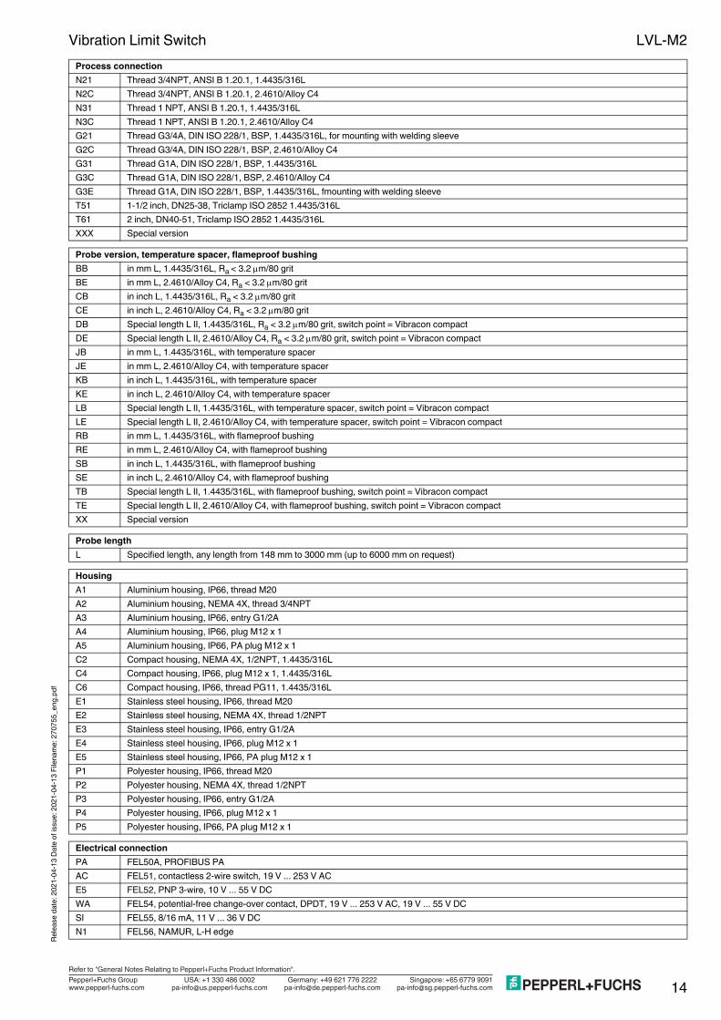
Vibration Limit SwitchProcess connectionN21 Thread 3/4NPT, ANSI B 1.20.1, 1.4435/316LN2C Thread 3/4NPT, ANSI B 1.20.1, 2.4610/Alloy C4N31 Thread 1 NPT, ANSI B 1.20.1, 1.4435/316LN3C Thread 1 NPT, ANSI B 1.20.1, 2.4610/Alloy C4G21 Thread G3/4A, DIN ISO 228/1, BSP, 1.4435/316L, for mounting with welding sleeveG2C Thread G3/4A, DIN ISO 228/1, BSP, 2.4610/Alloy C4G31 Thread G1A, DIN ISO 228/1, BSP, 1.4435/316LG3C Thread G1A, DIN ISO 228/1, BSP, 2.4610/Alloy C4G3E Thread G1A, DIN ISO 228/1, BSP, 1.4435/316L, fmounting with welding sleeveT51 1-1/2 inch, DN25-38, Triclamp ISO 2852 1.4435/316LT61 2 inch, DN40-51, Triclamp ISO 2852 1.4435/316LXXX Special version
Probe version, temperature spacer, flameproof bushingBB in mm L, 1.4435/316L, Ra < 3.2 m/80 gritBE in mm L, 2.4610/Alloy C4, Ra < 3.2 m/80 gritCB in inch L, 1.4435/316L, Ra < 3.2 m/80 gritCE in inch L, 2.4610/Alloy C4, Ra < 3.2 m/80 gritDB Special length L II, 1.4435/316L, Ra < 3.2 m/80 grit, switch point = Vibracon compactDE Special length L II, 2.4610/Alloy C4, Ra < 3.2 m/80 grit, switch point = Vibracon compactJB in mm L, 1.4435/316L, with temperature spacerJE in mm L, 2.4610/Alloy C4, with temperature spacerKB in inch L, 1.4435/316L, with temperature spacerKE in inch L, 2.4610/Alloy C4, with temperature spacerLB Special length L II, 1.4435/316L, with temperature spacer, switch point = Vibracon compactLE Special length L II, 2.4610/Alloy C4, with temperature spacer, switch point = Vibracon compactRB in mm L, 1.4435/316L, with flameproof bushingRE in mm L, 2.4610/Alloy C4, with flameproof bushingSB in inch L, 1.4435/316L, with flameproof bushingSE in inch L, 2.4610/Alloy C4, with flameproof bushingTB Special length L II, 1.4435/316L, with flameproof bushing, switch point = Vibracon compactTE Special length L II, 2.4610/Alloy C4, with flameproof bushing, switch point = Vibracon compactXX Special version
Probe lengthL Specified length, any length from 148 mm to 3000 mm (up to 6000 mm on request)
HousingA1 Aluminium housing, IP66, thread M20A2 Aluminium housing, NEMA 4X, thread 3/4NPTA3 Aluminium housing, IP66, entry G1/2AA4 Aluminium housing, IP66, plug M12 x 1A5 Aluminium housing, IP66, PA plug M12 x 1C2 Compact housing, NEMA 4X, 1/2NPT, 1.4435/316LC4 Compact housing, IP66, plug M12 x 1, 1.4435/316LC6 Compact housing, IP66, thread PG11, 1.4435/316LE1 Stainless steel housing, IP66, thread M20E2 Stainless steel housing, NEMA 4X, thread 1/2NPTE3 Stainless steel housing, IP66, entry G1/2AE4 Stainless steel housing, IP66, plug M12 x 1E5 Stainless steel housing, IP66, PA plug M12 x 1P1 Polyester housing, IP66, thread M20P2 Polyester housing, NEMA 4X, thread 1/2NPTP3 Polyester housing, IP66, entry G1/2AP4 Polyester housing, IP66, plug M12 x 1P5 Polyester housing, IP66, PA plug M12 x 1
Electrical connectionPA FEL50A, PROFIBUS PAAC FEL51, contactless 2-wire switch, 19 V ... 253 V ACE5 FEL52, PNP 3-wire, 10 V ... 55 V DCWA FEL54, potential-free change-over contact, DPDT, 19 V ... 253 V AC, 19 V ... 55 V DCSI FEL55, 8/16 mA, 11 V ... 36 V DCN1 FEL56, NAMUR, L-H edge

Relea
se da
te: 20
21-04
-13 D
ate of
issu
e: 20
21-04
-13 F
ilena
me: 2
7075
5_en
g.pdf
LVL-M2
15Germany: +49 621 776 2222Pepperl+Fuchs GroupRefer to "General Notes Relating to Pepperl+Fuchs Product Information".
USA: +1 330 486 0002 Singapore: +65 6779 9091www.pepperl-fuchs.com [email protected] [email protected]@de.pepperl-fuchs.com
Vibration Limit Switch
N2 FEL58, NAMUR with push button, H-L edgeElectrical connection

Relea
se da
te: 20
21-04
-13 D
ate of
issu
e: 20
21-04
-13 F
ilena
me: 2
7075
5_en
g.pdf
LVL-M2
16Germany: +49 621 776 2222Pepperl+Fuchs GroupRefer to "General Notes Relating to Pepperl+Fuchs Product Information".
USA: +1 330 486 0002 Singapore: +65 6779 9091www.pepperl-fuchs.com [email protected] [email protected]@de.pepperl-fuchs.com
Vibration Limit Switch
Welding sleeves• LVL-Z100, welding sleeve G3/4 for flush mounting for process connection G21• LVL-Z101, welding sleeve G1 for flush mounting for process connection G3E• LVL-Z102, welding sleeve G1 for flush mounting for process connection G3EFlanges• LVL-Z105, lap joint round flange DN50 PN40 form A with G1 thread for process connection G31• LVL-Z106, lap joint round flange ANSI 2 inch with G1 thread for process connection G31• LVL-Z107, lap joint square flange with G1 thread for process connection G31Sliding sleeves• LVL-Z120, sliding sleeve for unpressurised operation G1A• LVL-Z121, sliding sleeve for unpressurised operation G1-1/2A• LVL-Z122, sliding sleeve for unpressurised operation 1 NPT• LVL-Z123, sliding sleeve for unpressurised operation 1-1/2 NPT• LVL-Z124, high pressure sliding sleeve G1A• LVL-Z125, high pressure sliding sleeve G1A, Alloy C4/2.4610• LVL-Z126, high pressure sliding sleeve G1-1/2A• LVL-Z127, high pressure sliding sleeve G1-1/2A, Alloy C4/2.4610• LVL-Z128, high pressure sliding sleeve 1 NPT• LVL-Z129, high pressure sliding sleeve 1 NPT, Alloy C4/2.4610• LVL-Z130, high pressure sliding sleeve 1-1/2 NPT• LVL-Z131, high pressure sliding sleeve 1-1/2 NPT, Alloy C4/2.4610Further accessories• LVL-Z108, cover with glass sight glass for stainless steel housing E*• LVL-Z109, cover with PC sight glass for stainless steel housing E*• LVL-Z110, transparent cover for polyester housing P*• V1-G, mating connector, straight• V1-W, mating connector, 90° angled
Additional equipmentNA without additional equipmentZ3 3.1.B material, wetted parts 1.4435, inspection certificate to EN 10204
ApprovalNA Version for non-hazardous areaWH WHG overfill protectionE1 ATEX II 1G EEx ia IIC T6E2 ATEX II 1/2G EEx ia IIC T6E3 ATEX II 1/2G EEx d IIC T6EA ATEX II 1G EEx ia IIC T6, WHGEB ATEX II 1/2G EEx ia IIC T6, WHGEC ATEX II 1/2G EEx d IIC T6, WHGEM ATEX II 3G EEx nA IIC T6, WHGEN ATEX II 3G EEx nC IIC T6, WHGFI FM IS, CI. I, II, III, Div. 1, Gr. A-GFN FM NI, CI. I, Div. 2, Gr. A-DFX FM XP, CI. I, II, III, Div. 1, Gr. A-GCG CSA General PurposeCI CSA IS, CI. I, II, III, Div. 1, Gr. A-GCX CSA XP, CI. I, II, III, Div. 1, Gr. A-G
Accessories