vibration monitoring unit he100 series - hauber-elektronik · hauber-elektronik gmbh instruction...
TRANSCRIPT

Betriebsanleitung
englisch
Vibration monitoring unit
HE100 series
• Vibration velocity (mm/s, rms)
• ATEX / IECEx / EACEx Zone 1 / 2 / 21 / 22
• Analogue current output: 4–20 mA
• Frequency ranges: 10 Hz–1,000 Hz 1 Hz–1,000 Hz
Manufacturing date:
Type designation:
Serial number:

HAUBER-Elektronik GmbH
Instruction Manual Vibration monitoring unit Type HE100 Standard and ATEX / IECEx / EACEx
HE100
Version: 2020-03-27
Attention!
Prior to commissioning the product, the instruction manual must be read and understood.
All rights, including translation, are reserved.
Subject to changes.
Should any question arise, please contact:
HAUBER-Elektronik GmbH Fabrikstraße 6 72622 Nürtingen Germany
Tel.: +49 (0) 7022 / 21750-0 Fax: +49 (0) 7022 / 21750-50
www.hauber-elektronik.de
HAUBER-Elektronik GmbH
3
1 Table of contents
1 Table of contents ...................................................................................................................................... 3
2 Safety information .................................................................................................................................... 4
2.1 General ................................................................................................................................................. 4
2.2 Symbols used ....................................................................................................................................... 4
3 Scope of this instruction manual .............................................................................................................. 4
4 Vibration monitoring unit type HE100 ....................................................................................................... 5
5 Intended use ............................................................................................................................................. 5
6 Scope of supply ........................................................................................................................................ 5
7 Documents and certificates ...................................................................................................................... 5
8 Transfer of liability when operating in potentially explosive atmospheres ............................................... 5
9 Application areas and type plate examples .............................................................................................. 6
10 General Conditions for Safe Operation .................................................................................................... 7
10.1 HE100.01 (protection ‘pressure resistant housing’) .............................................................................. 7
10.2 HE100.02 (ignition protection class "intrinsically safe") ........................................................................ 7
11 Technical data .......................................................................................................................................... 9
11.1 General data ......................................................................................................................................... 9
11.2 Electrical data ....................................................................................................................................... 9
11.3 Permitted operating temperature ranges ............................................................................................ 10
11.4 Operating range of the vibration monitoring unit ................................................................................ 11
11.5 Typical frequency response ................................................................................................................ 12
11.6 Mechanical data .................................................................................................................................. 13
11.7 Housing dimensions............................................................................................................................ 13
12 Connections ............................................................................................................................................ 15
13 Assembly and disassembly .................................................................................................................... 16
13.1 General notes ..................................................................................................................................... 16
13.2 Fixing the vibration monitoring unit to the mounting surface .............................................................. 16
14 Installation and commissioning .............................................................................................................. 17
14.1 General notes ..................................................................................................................................... 17
14.2 Wiring diagram .................................................................................................................................... 17
15 Maintenance and repair .......................................................................................................................... 19
15.1 General notes ..................................................................................................................................... 19
15.2 Fault resolution table .......................................................................................................................... 19
16 Transport, storage and disposal ............................................................................................................. 20
17 Accessories ............................................................................................................................................ 20
18 HE100 type code .................................................................................................................................... 21
19 EU declaration of conformity .................................................................................................................. 22

HAUBER-Elektronik GmbH
4
2 Safety information
2.1 General
The safety information is designed to protect people and property from damage and hazards resulting from unintended use, incorrect operation or other negligent handling of devices, especially in potentially explosive atmospheres. For this reason, you should read this instruction manual carefully before undertaking any work on the product or commissioning it. The instruction manual must be accessible to operating personnel at any time.
Please check that all documentation is in place prior to commissioning or other work on the product. If not all documentation has been handed over in full, or if further copies are required, then they can also be sourced in other languages.
The product has been constructed to the state of the art. Nevertheless, it is impossible to rule out dangers emerging from this product which could endanger people, machines and systems, should it be subject to inappropriate handling, non-intended use or use and maintenance by insufficiently trained persons.
Every person employed by the operator and involved in the set-up, operation and maintenance of this product must have read and understood this instruction manual.
The product may only be assembled, disassembled, installed and repaired by instructed, sufficiently trained and authorised personnel.
2.2 Symbols used
This symbol indicates a risk of explosion.
This symbol indicates a risk of electric shock.
This symbol points to non-safety-related information.
3 Scope of this instruction manual
This instruction manual for the HE100-type vibration monitoring unit applies to the following variants: Standard / ATEX / IECEx / EACEx
The functionality of the versions is identical. The ATEX / IECEx / EACEx versions also possess certifications and labels which permit use in potentially explosive atmospheres. For further information, see chapter "Application areas and type plate examples” on page 6.

HAUBER-Elektronik GmbH
5
4 Vibration monitoring unit type HE100
The HE100-type vibration monitoring unit is used to measure and monitor absolute bearing vibrations in machines in line with DIN ISO 10816. It has the following features:
• Operating principle: The two-wire system.
• Measurement value: The effective value (rms) of the vibration velocity in mm/s, in accordance with DIN ISO 2954.
• Analogue current output: Interference-free DC signal from 4–20 mA, proportional to the measuring range of the monitoring unit.
• Cable breaks on the monitoring cable can be detected by a downstream evaluation component: DC signal value < 3.5 mA.
5 Intended use
The HE100-type is used exclusively for measuring mechanical vibrations in machines and mechanical systems. Its use is only permissible within the specifications stated in the data sheet. Main fields of application: Fans, ventilators, blowers, electric motors, pumps, centrifuges, separators, generators, turbines and similar oscillating mechanical systems.
6 Scope of supply
All versions include:
• Vibration monitoring unit
• Instruction Manual
7 Documents and certificates
The following documents and certificates pertaining to type HE100 can be viewed and downloaded here: http://www.hauber-elektronik.de/english/index.html
• EC type examination certificate ATEX; no.: PTZ 16 ATEX 0029 X
• EC type examination certificate IECEx; no.: PTZ 18.0009 X
• EACEx certificate RU C-DE.HA65.B.00053/19
• EAC declaration
8 Transfer of liability when operating in potentially explosive atmospheres
The owner of the system is exclusively liable for the appropriate configuration of the electrical connections with respect to explosion protection regulations and correct commissioning.
If the system is installed by a sub-contractor on behalf of the owner, the system may only be commissioned after the sub-contractor has issued written confirmation in the form of a certificate of installation that the system has been installed correctly and professionally in accordance with the applicable legal regulations.
The operator is obliged to notify the responsible authorities of the initial commissioning of explosion-protected systems or system components and their re-commissioning following extensive changes or maintenance.

HAUBER-Elektronik GmbH
6
9 Application areas and type plate examples
Vers
ion
Standard CE / IEC /EAC UL Proc. Cont. Eq. for Ord. Loc.
ATEX / IECEx / EACEx Pressure-resistant casing, Ex db Protection through housing, Ex tb
ATEX / IECEx / EACEx Intrinsic safety Ex ib
Ap
pli
cati
on
are
a
Atmospheres not at risk of explosion
Potentially explosive atmospheres of zones 1 and 21 2 and 22
Potentially explosive atmospheres of zones 1 and 21 2 and 22
Ma
rkin
g
Ty
pe p
late
Standards applied
You can find a list of standards, including the related issue dates, in the EU type examination certificate for the vibration monitoring unit.

HAUBER-Elektronik GmbH
7
10 General Conditions for Safe Operation
The following conditions must be met for safe operation in potentially explosive atmospheres.
10.1 HE100.01 (protection ‘pressure resistant housing’)
Electrical data
min typ. max.
Supply voltage Un 10 V DC 24 V DC 30 V DC
Current In 4 mA 4...20 mA 25 mA
Tabular 1: Electrical data HE100.01
10.2 HE100.02 (ignition protection class "intrinsically safe")
With the ignition protection class intrinsically safe Ex ib IIC or IIC, the sensor
must only be operated in a certified intrinsically safe electrical circuit. The
maximum values must not be exceeded.
The following values relate to the vibration monitoring unit and the supply and
signal circuit.
Electrical data
Max. input voltage of the vibration monitoring unit Ui 30 V DC
Max. input current of the vibration monitoring unit Ii 25 mA
Max. input power of the vibration monitoring unit Pi 600 mW
Capacity of the vibration monitoring unit Ci 44 nF
Inductance of the vibration monitoring unit Li 0 µH
Tab. 2: HE100.02 electrical data
HAUBER-Elektronik GmbH
8
Other conditions
1. Extended ambient temperature range of -40°C to +60°C
2. Equipotential bonding takes place during installation.
3. The instruction manual is to be heeded.
4. The following feed/inlet isolating amplifiers are tested and approved by Hauber-Elektronik GmbH for intrinsically safe operation:
• Endress und Hauser Active barrier RN221N with HART® diagnosis
• PHOENIX CONTACT Deutschland GmbH feed and isolating amplifier MACX MCR-EX-SL-RPSSII 2865340
• Pepperl+Fuchs SMART transmitter supply unit KFD2-STC3-Ex1
• R. STAHL Schaltgeräte GmbH transducer supply unit 9260/13-11-10s art. no. 261384
5. The Ex i version must only be operated with the Ex i cable approved by Hauber-Elektronik. On this cable, pin 5 of the M12 connector is assigned to the cable shield. (HE article number: 11141 (2m), 11142 (5m), 11143 (10m), additional lengths available in stock)
HAUBER-Elektronik is not responsible for changes to the specification of the feed/inlet isolating amplifier mentioned.

HAUBER-Elektronik GmbH
9
11 Technical data
11.1 General data
Each sensor has one of the measuring and frequency ranges listed. Additional
ranges upon request.
Please specify the measuring and frequency range in your query.
Measuring range: 0–8 mm/s (only for frequency range > 10 Hz)
0–16 mm/s
0–32 mm/s
0–64 mm/s 0–64 mm/s
Measurement accuracy: ±10% (as per DIN ISO 2954)
Cross-sensitivity: < 5%
Frequency range: 10 Hz–1,000 Hz (standard)
1 Hz–1,000 Hz
Calibration point 159.2 Hz and 90% amplitude of the measuring range
Maximum acceleration ±16.5 g
Service life 10 years
MTTF 399 years
Tab. 3: General data
11.2 Electrical data
Output signal: 4–20 mA (proportional to the measuring range)
Voltage supply: 10–30 V DC
Current draw (max.): 25 mA
Apparent ohmic resistance/load (max.):
500 Ω
Fuse*: 30VDC, 3A, medium blow
* Ensure that the supply line is protected by a UL-approved fuse for UL-compliant sensor operation.
Tab. 4: Electrical data

HAUBER-Elektronik GmbH
10
11.3 Permitted operating temperature ranges
Version Ambient temperature
(TA)
Measuring head temperature
(in the fixing area)
Standard -40°C to +60°C -40 °C to +125°C
ATEX / IECEx / EACEx
Pressure-resistant casing, Ex d
Protection through housing, Ex tb
-40 °C to +60 °C -40 °C to +125°C
ATEX / IECEx / EACEx
Intrinsic safety Ex ib
-40 °C to +60 °C -40 °C to +125°C
Tab. 5: Permitted operating temperature ranges

HAUBER-Elektronik GmbH
11
11.4 Operating range of the vibration monitoring unit
The operating range is independent of the measuring range. It is deduced from the maximum acceleration, which is 16.5 g across all frequencies. The maximum measurable vibration velocity is determined by the formula
𝑣𝑚𝑎𝑥 = ∫ 𝑎𝑚𝑎𝑥
The following applies to sinusoidal vibration
𝑣𝑚𝑎𝑥 = 𝑎𝑚𝑎𝑥
2𝜋𝑓
Fig. 1: shows the operating range of the vibration monitoring unit, which is limited by the maximum measurable vibration velocity in mm/s depending on the frequency in Hz.
Fig. 1: Operating range diagram
1 Frequency in Hz
2 Vibration velocity in mm/s
3 Operating range of the vibration monitoring unit
Reading examples:
Frequency
(Hz)
Maximum measurable
Vibration velocity
(mm/s)
250 103
400 64
1,000 25
Tab. 6: Operating range reading examples
0
20
40
60
80
100
120
140
160
180
200
0 100 200 300 400 500 600 700 800 900 1000
2 →
1→
3
HAUBER-Elektronik GmbH
12
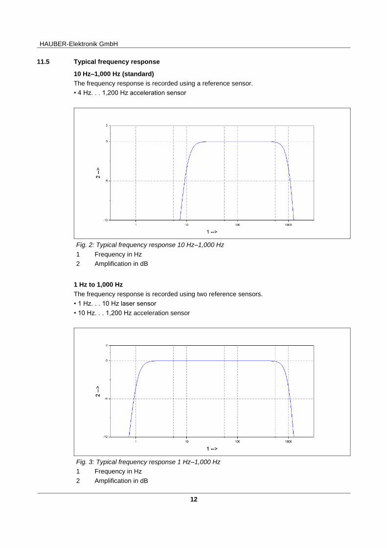
11.5 Typical frequency response
10 Hz–1,000 Hz (standard)
The frequency response is recorded using a reference sensor.
• 4 Hz. . . 1,200 Hz acceleration sensor
Fig. 2: Typical frequency response 10 Hz–1,000 Hz
1 Frequency in Hz
2 Amplification in dB
1 Hz to 1,000 Hz
The frequency response is recorded using two reference sensors.
• 1 Hz. . . 10 Hz laser sensor
• 10 Hz. . . 1,200 Hz acceleration sensor
Fig. 3: Typical frequency response 1 Hz–1,000 Hz
1 Frequency in Hz
2 Amplification in dB

HAUBER-Elektronik GmbH
13
11.6 Mechanical data
Additional materials and fixings can be found in section "HE100 type code" on
page 21.
Housing material: Stainless steel V2A, material no.: 1.4305 (standard)
Fixing: Width A/F 24 (hex) M8 x 8 mm Incline: 1.25 mm (standard)
Assembly type: Standing/vertical or lying/horizontal
Measurement direction Along the fixing axis
Max. torque oft the Sensor 8 Nm
Max. torque of the M12 union nut on the connector
0.4 Nm
Weight: ca. 200 g
Protection class: IP 66/67 (in mated condition)
Tab. 7: Mechanical data
11.7 Housing dimensions
Versi on: Standar d and ATEX / IECEx / EACEx
11.7.1 Version: Standard and ATEX / IECEx / EACEx Intrinsic safety, Ex i
Fig. 4: Housing with M12 connector All dimensions in mm
1 M12 connector
2 Width A/F 24
3 Fixing
4 Measuring direction along the fixing axis

HAUBER-Elektronik GmbH
14
11.7.2 Version: ATEX / IECEx / EACEx Ex d
Fig. 5: Housing with integrated cable All dimensions in mm
1 Cable gland for integrated cable
2 Width A/F 24
3 Fixing
4 Measuring direction along the fixing axis

HAUBER-Elektronik GmbH
15
12 Connections
Version: Standard
Plug, M12, 4-pole Pin 1: 10…30 V DC
Pin 2: NC
Pin 3: 4…20 mA
Pin 4: NC
NC: Not Connected
Version: ATEX / IECEx / EACEx pressure-resistant casing Ex d ATEX / IECEx / EACEx protection through housing, Ex tb
integrated cable
brown Pin 1: 10…30 V DC
white Pin 2: NC
blue Pin 3: 4…20 mA
black Pin 4: NC
PUR sheathed cable; Ø: approx. 6.5 mm,
4-pole, 0.34 mm² NC: Not connected
Version: ATEX / IECEx / EACEx intrinsic safety Ex i
Plug, M12, 5-pole Pin 1: 10…30 V DC
Pin 2: NC
Pin 3: 4…20 mA
Pin 4: NC
Pin 5: Sensor housing
NC: Not Connected
The system operates according to the two-wire principle.
I.e. the entire function (voltage supply and current signal) is achieved using 2
wires (Pin 1 and Pin 3).
To avoid capacitive interference, pins 2 and 4 must remain open/unoccupied.

HAUBER-Elektronik GmbH
16
13 Assembly and disassembly
13.1 General notes
Assembly and disassembly work on and with the vibration monitoring unit may only be performed by an authorised specialist familiar with the safety regulations governing handling electrical components.
The housing of the vibration monitoring unit must be earthed via the fixing –
through the machine earth of the mounting surface or through a separate
protective conductor (PE).
13.2 Fixing the vibration monitoring unit to the mounting surface
13.2.1 Prerequisites
• Mounting surface is clean and flat; i.e. free of paint, rust, etc.
• Measuring head area of the vibration monitoring unit must lie flat on the mounting surface.
13.2.2 Tool
• Hex key, width A/F 24
13.2.3 Work steps and instructions
• Screw vibration monitoring unit into the threaded hole of the mounting surface in a friction-locked manner using a hex key. The tightening torque should be 8 Nm.
• The tightening torque of the M12 union nut of the plug connection must not exceed 0.4 Nm
To obtain precise measurement values, the vibration monitoring unit must be
fixed to the mounting surface in a friction-locked manner.
Auxiliary structures for fixing are to be avoided. If unavoidable, make them as
firm as possible!
Earth/ground loops are amongst the most common problems in measurement
set-ups with sensitive sensor technology. These issues arise due to
unintentional differences in potential in the electrical circuit between the sensor
and evaluation unit. As a countermeasure, we recommend our standard
earthing concept or, depending on the application our Alternative earthing
concept
Ensure that the earth connection is electrically secure.
HAUBER-Elektronik GmbH
17
14 Installation and commissioning
14.1 General notes
Installation and commissioning the vibration monitoring unit must be performed by an
authorised specialist who is familiar with the safety regulations when handling
electrical components.
Protect the connection cable and any extension cables from electrical
interference or mechanical damage. Comply with the local regulations and
directives.
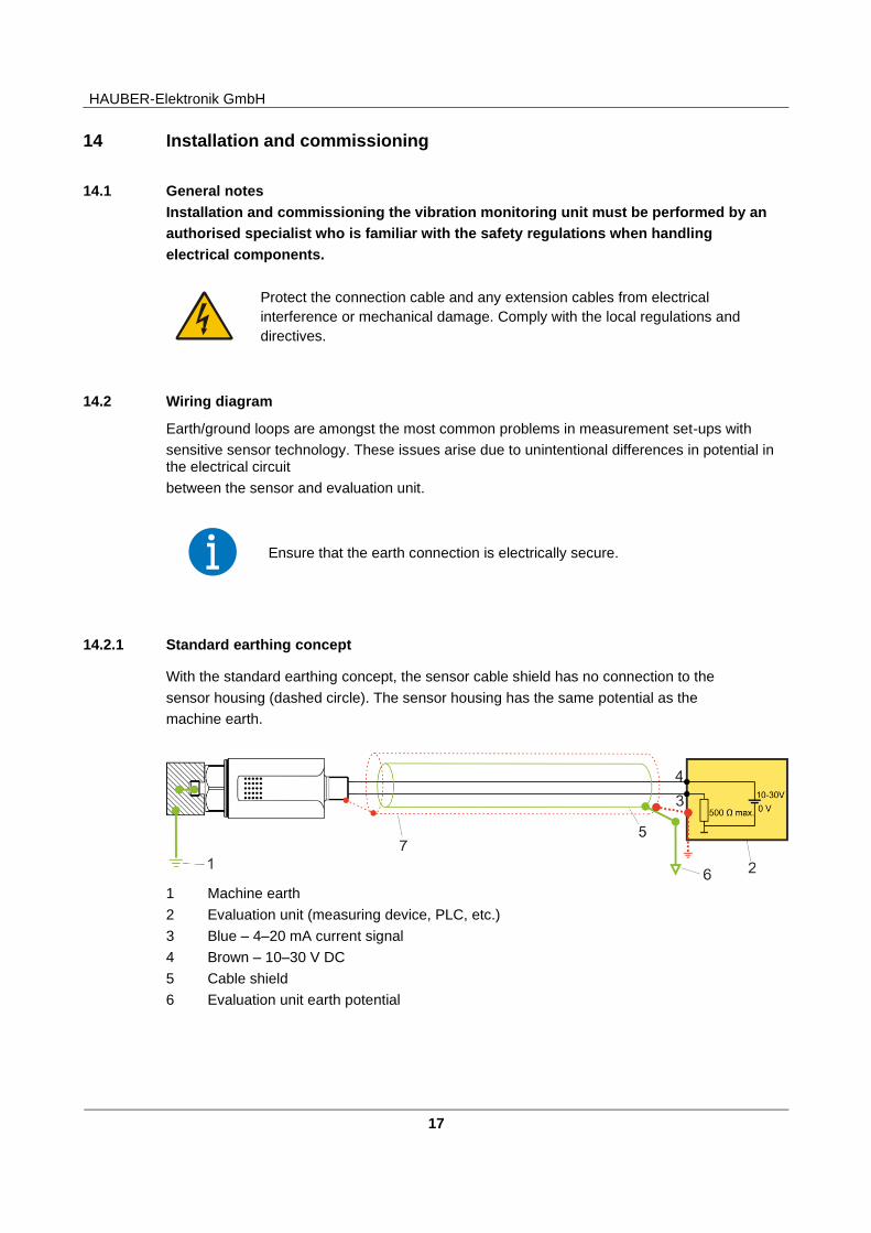
14.2 Wiring diagram
Earth/ground loops are amongst the most common problems in measurement set-ups with
sensitive sensor technology. These issues arise due to unintentional differences in potential in the electrical circuit
between the sensor and evaluation unit.
Ensure that the earth connection is electrically secure.
14.2.1 Standard earthing concept
With the standard earthing concept, the sensor cable shield has no connection to the
sensor housing (dashed circle). The sensor housing has the same potential as the
machine earth.
1 Machine earth
2 Evaluation unit (measuring device, PLC, etc.)
3 Blue – 4–20 mA current signal
4 Brown – 10–30 V DC
5 Cable shield
6 Evaluation unit earth potential

HAUBER-Elektronik GmbH
18
14.2.2 Alternative earthing concept
With the alternative earthing concept, the sensor cable shield is connected to the sensor housing. The sensor housing is uncoupled from the machine earth by means of an EMC adapter (red). With the alternative earthing concept, an electrically secure earth connection can only be ensured for versions with an M12 plug connection. For versions with an integrated cable, the alternative earthing concept cannot be used.
1 Machine earth
2 Evaluation unit (measuring device, PLC, etc.)
3 Blue – 4–20 mA current signal
4 Brown – 10–30 V DC
5 Cable shield
6 Evaluation unit earth potential
7 EMC adapter (Hauber art. no. 10473)
Please advise us if you are opting for the alternative earthing concept when
enquiring. We will offer you the relevant sensor cable and the EMC adapter.
14.2.3 Potentially explosive atmosphere, Ex i earthing concept
For the Ex i sensor, the shield is routed via Pin 5 of the plug connection to the potential of the sensor housing, which is typically on the machine earth.

HAUBER-Elektronik GmbH
19
1 Machine earth
2 The shield of the Ex i cable is on the potential of the housing via Pin 5 of M12 connector
3 Do not earth the shield
4 Evaluation unit (measuring device, PLC, etc.)
5 Power supply
6 Hauber Ex i sensor
7 Isolating amplifier
8 Potentially explosive atmospheres of zones 1 and 21 / 2 and 22
9 Area not at risk
15 Maintenance and repair
15.1 General notes
Repair and cleaning work on vibration monitoring units may only be performed
by an authorised specialist familiar with the safety regulations governing
handling electrical components.
Replace defective cables immediately!
A defective vibration monitoring unit must be completely replaced.
The vibration monitoring unit HE100 is maintenance-free.
15.2 Fault resolution table
Fault Cause Action
No measured value
(4-20 mA)
No voltage supply Check voltage source and/or supply cable
Connection cable interrupted Replace connection cable
Fuse defective Replace fuse
Connection has incorrect polarity Establish correct connection polarity
Vibration monitoring unit defective Replace vibration control unit
Incorrect
measurement value
Vibration monitoring unit not friction-locked.
Mount vibration monitoring unit in a friction-locked manner.
Vibration monitoring unit mounted in wrong position.
Mount vibration monitoring unit in correct position.
EMC problems
For further information, see chapter "Alternative earthing concept” on page 18.
Tab. 8: Fault resolution table

HAUBER-Elektronik GmbH
20
16 Transport, storage and disposal
The sensor must be protected by suitable packaging against damaging environmental influences and against mechanical damage during transport.
The sensor must not be stored in ambient temperatures beyond the permitted operating temperature.
The product contains electronic components and must be disposed of in a proper manner according to local regulations and legislation.
17 Accessories
Accessories
Sta
ndard
AT
EX
/ I
EC
Ex / E
AC
Ex E
x d
, tb
AT
EX
/ I
EC
Ex /
EA
CE
x E
x i
Factory calibration certificate – Art-No.:10419 x x x
Evaluation device types 652 and 656 x x x
HE400-type portable measuring instrument x
ATEX / IECEx / EACEx supply isolation amplifier for intrinsic safety Ex I – Art-No.:10993
x
Magnetic base – Art-No.:10054 x
Various mounting adapters; e.g. M8 -> M10 x x x
Configurable mating plug x x
Connection cable, socket M12, 4-pin, 0.34 mm²,
L= 2 m, 5 m, 10 m, or customised x
ATEX / IECEx / EACEx connection cable for intrinsic safety Ex i, M12, 4-pin, 0.34 mm²,
L= 2 m, 5 m, 10 m, or customised
x
Rubber nozzle– Art-No.:10986 x x x
Metallic protective hose x x x
EMC adapter – Art-No.:10473 x
For use OUTDOORS or using SPRAY WATER, the
vibration monitoring unit should have the rubber nozzle
pulled over it for additional protection. Rubber nozzle
HAUBER-Elektronik GmbH
21
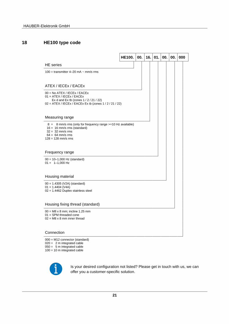
18 HE100 type code
Is your desired configuration not listed? Please get in touch with us, we can
offer you a customer-specific solution.
HE100. 00. 16. 01. 00. 00. 000
HE series
100 = transmitter 4–20 mA ~ mm/s rms
ATEX / IECEx / EACEx
00 = No ATEX / IECEx / EACEx 01 = ATEX / IECEx / EACEx Ex d and Ex tb (zones 1 / 2 / 21 / 22) 02 = ATEX / IECEx / EACEx Ex ib (zones 1 / 2 / 21 / 22)
Measuring range
8 = 8 mm/s rms (only for frequency range >=10 Hz available) 16 = 16 mm/s rms (standard) 32 = 32 mm/s rms 64 = 64 mm/s rms 128 = 128 mm/s rms
Frequency range
00 = 10–1,000 Hz (standard) 01 = 1–1,000 Hz
Housing material
00 = 1.4305 (V2A) (standard) 01 = 1.4404 (V4A) 02 = 1.4462 Duplex stainless steel
Housing fixing thread (standard)
00 = M8 x 8 mm; incline 1.25 mm 01 = SPM threaded cone 02 = M8 x 8 mm inner thread
Connection
000 = M12 connector (standard) 020 = 2 m integrated cable 050 = 5 m integrated cable 100 = 10 m integrated cable
HAUBER-Elektronik GmbH
22
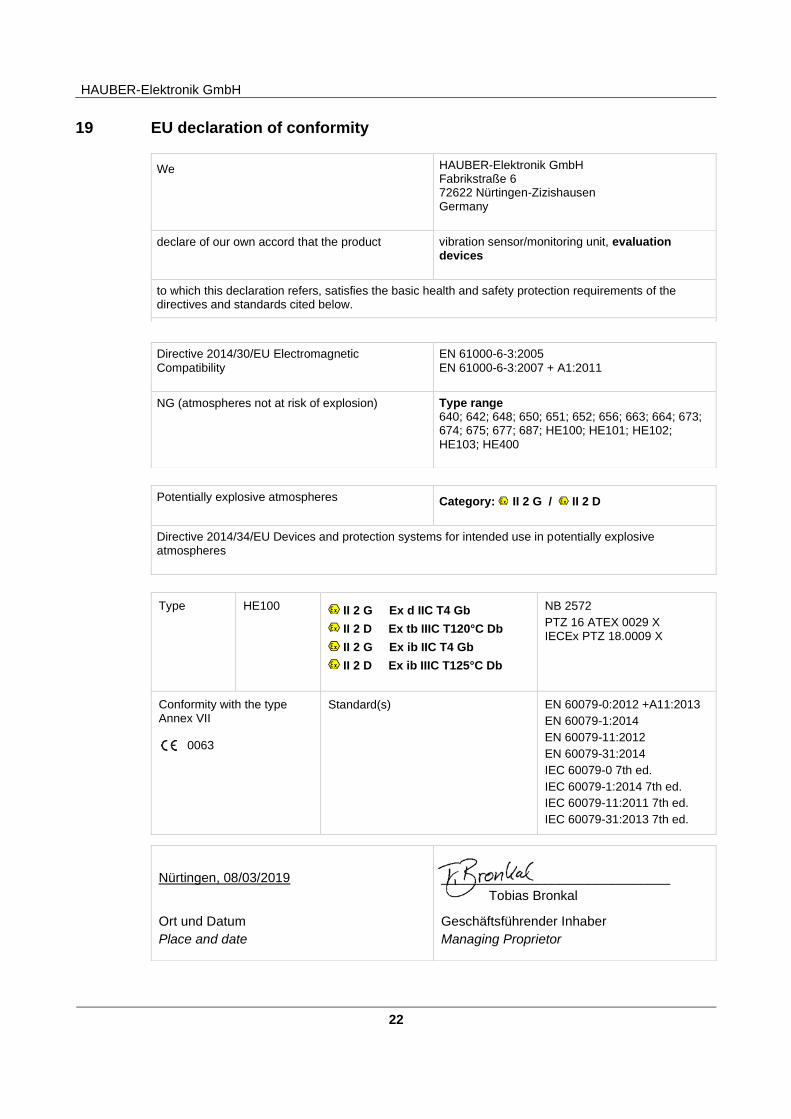
19 EU declaration of conformity
Potentially explosive atmospheres Category: II 2 G / II 2 D
Directive 2014/34/EU Devices and protection systems for intended use in potentially explosive atmospheres
Type HE100 II 2 G Ex d IIC T4 Gb
II 2 D Ex tb IIIC T120°C Db
II 2 G Ex ib IIC T4 Gb
II 2 D Ex ib IIIC T125°C Db
NB 2572
PTZ 16 ATEX 0029 X IECEx PTZ 18.0009 X
Conformity with the type Annex VII
0063
Standard(s)
EN 60079-0:2012 +A11:2013
EN 60079-1:2014
EN 60079-11:2012
EN 60079-31:2014
IEC 60079-0 7th ed.
IEC 60079-1:2014 7th ed.
IEC 60079-11:2011 7th ed.
IEC 60079-31:2013 7th ed.
We HAUBER-Elektronik GmbH Fabrikstraße 6 72622 Nürtingen-Zizishausen Germany
declare of our own accord that the product vibration sensor/monitoring unit, evaluation devices
to which this declaration refers, satisfies the basic health and safety protection requirements of the directives and standards cited below.
Directive 2014/30/EU Electromagnetic
Compatibility
EN 61000-6-3:2005
EN 61000-6-3:2007 + A1:2011
NG (atmospheres not at risk of explosion) Type range 640; 642; 648; 650; 651; 652; 656; 663; 664; 673; 674; 675; 677; 687; HE100; HE101; HE102;
HE103; HE400
Nürtingen, 08/03/2019
Ort und Datum
Place and date
_______________________________
Tobias Bronkal
Geschäftsführender Inhaber
Managing Proprietor