vibration of cavitating hydrofoils
TRANSCRIPT

UNIVERSITY OF MINNESOTA
ST. ANTHONY FALLS HYDRAULIC LABORATORY
Project Report No. 111
Vibration of Cavitating Hydrofoils
by CHARLES C. S. SONG
This research was carried out under the Naval Ship Systems Command Hydrofoil Exploratory Development Program SF 013 0201, administered by the Naval Ship Research and Development Center. Prepared under the Office of Naval Research Contract NOOO 14-67·A·0 1 13·0005.
OCTOBER 1969
MINNEAPOLIS, MINNESOTA
This document has been approved for public release and sale; its distribution is unlimited.
Reproduction in whole or in part is permitted
for any purpose of the United States Government

CONTENTS
List of Illustrations • • • • • • • • • • , ., . Table of Notation
(It • • (It • .. • (It • • (It (It • ~ (It (It
Abstract. • • • • • • • • • • • • (It • .. (It f • • • • •
I.
II.
III.
IV.
INTRODUCTION. • • • • • • • • • • • • • It (It • "
EXPERIMENTAL APPARATUS AND PROCEDURE. • , (It • •
EXPERIMENTAL RESULTS. • • (It ## • • • • • • • (It •
A. B.
Fully Developed Cavities ••• • • • • • (It
Partial Cavities. • • • • • • · , . , . . 1.
2.
Natural Frequency of Partial Cavities. • • • • • • " • • . . . Two Types of Flutter-Like Vibrations. • • • • • • • • • • (It (It
CONCLUSIONS • • • • • • • • • • • (It (It • • , (It •
List of References. • . . . • • • (It • • • (It • (It . . . Figures 1 through 20. • • • • • • • (It •. • • (It • (It , (It
-iii-
Page
iv
v
vii
1
3
4
6
7
8
11
13
1.5

LIST OF ILLUSTRATIONS
Figure
1 A view of the Two-Dimensional Test Section of the Free-Jet Water Tunnel
2 Cross-sectional Profiles of Test Bodies
3 Typical record of Free-Vibration Test
4 RMS values of Fluctuating Lift Coefficient for Fully Developed Cavities
5 RMS values of Fluctuating Drag Coefficient for Fully Developed Cavities
6 RMS values of Fluctuating Moment Coefficient for Fully Developed Cavities
7 Intensity of Cavity Pulsation as a function of Cavity Length for Ventilated Cavities
8 Autocorrelation of Fluctuating Lift of Non-Pulsating Cavity
9 Autocorrelation of Pulsating Cavity
10 Relative Intensity of Fluctuation for Short Cavities
11 Relative Intensity of Fluctuating Lift of a Stable Cavity
12 A Typical Record showing the Vibration predominantly due to SelfExcited Cavity Vibration
13 Natural Frequency of Short Cavities as a function of Cavity Length
14 Relative Intensity of Self-Excited Cavity Vibration as a function of Cavity Length
15 Typical records showing a Flutter-Like Vibration for a Symmetrical Wedge (Type 1)
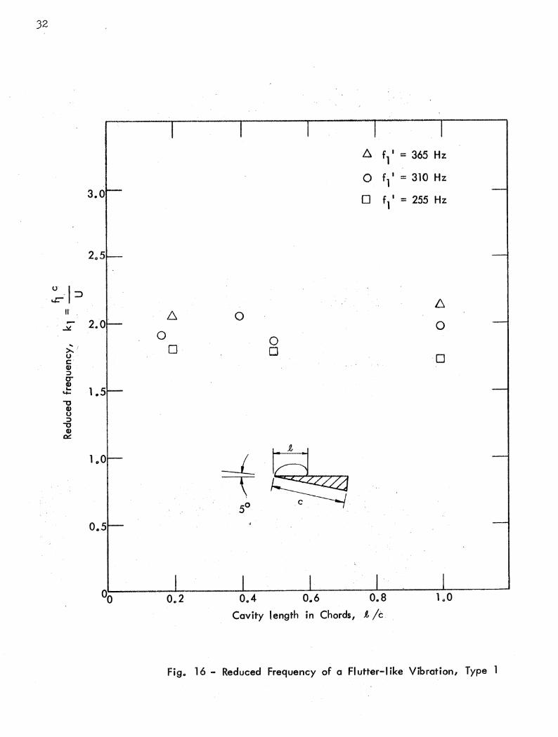
16 Reduced Frequency of a Flutter-Like Vibration, Type 1
17 A typical record of a Flutter-Like Vibration (Type 2) for a NonSymmetrical Wedge
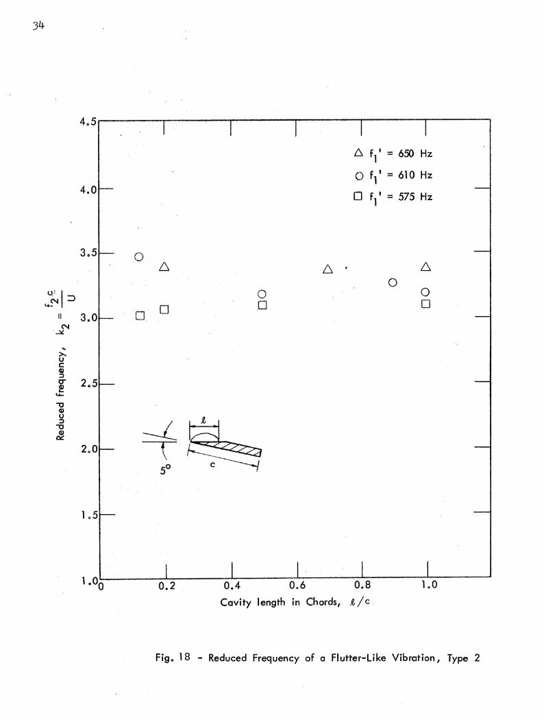
18 Reduced Frequency of a Flutter-Like Vibration, Type 2
19 Amplitude ratio of Flutter-Like Vibrations
20 Comparison of Frequency Ratios
-iv~

TABLE OF NOTATION
AL ~ amplitude of lift
~ ~ amplitude of moment
A* ~ amplitude ratio
C ~ chord length of the foil
CD ~ drag coefficient
CL ~ lift coefficient
CM ~ moment coefficient
D ~ drag
f ~ frequency
. fo ~ fundamental frequency of the cavity vibration
fl ~ frequency of the first type hydro elastic vibration
f2 ~ frequency of the second type hydroelastic vibration
f l ' ~ first natural frequency of the system in air
f2' ~ second natural frequency of the system in air
k ~ reduced frequency of the cavity Vibration o
~ ~ average cavity length
L ~ lift
L' ~ fluctuating component of the lift
M ~ moment
~ ~ autocorrelation of lift fluctuation
t ~ time
U ~ ambient speed
a ~ angle of attack
p ~ density of fluid
a ~ cavitation number based on vapor pressure v
'T ~ delay time
w = angular speed of Vibrations


ABSTRACT
A primarily experimental research program has been carried out
using a free-jet water tunnel for the purpose of studying force and
moment fluctuations on cavitating two-dimensional hydrofoils. Both a
symmetrical wedge and a non-symmetrical wedge were tested for a wide
range of cavity lengths and several different elastic conditions.
Fluctuations in lift and moment were of primary concern in the experi
ments.
It was revealed that the force and moment were quite steady if the
cavity was longer than two chords unless an excessive amount of ventila
tion caused cavity pulsations. For a shorter cavity, however, the flow
was generally very unstable, and severe vibrations were noted. A cavity
of any length was found to be basically unstable and to oscillate at
a characteristic frequency which was primarily a function of the cavity
length. The vibrating cavity may cause an elastically supported foil to
vibrate severely when the cavity is short. The largest-amplitude vibra
tion often occurred when the cavity length was approximately equal to
one chord.
Flutter-like vibrations were noted in the first and second natural
modes of the two-degree-of-freedom system. The frequency of these vibra
tions was found to be practically independent of the cavity length. The
severest vibration in the first natural mode usually occurred when the
average cavity length was approximately equal to one chord, whereas vi
bration in the second natural mode was found more likely to occur when
the cavity was very short.
-vii-


--- ._ ... _-_ .. ---
VIBRATION OF CAVITATING HYDROFOILS
I. INTRODUCTION
Cavitation has long been recognized as a serious problem for those
concerned with hydraulic machinery or structures which may be exposed to a
low-pressure field in a flowing liquid. Cavitation damage, cavitation
noise, and reduction of efficiency are frequently associated with cavitat
ing bodies. Design of lifting bodies to operate at cavitating conditions
with acceptable performance has been under study by various investigators
. during the past two decades. A great impetus was given to research in
this field when linearized potential flow theory was first used by Tulin * .
[lJ to estimate the steady load on supercavitating bodies. Since then a
great· number of papers have been written on methods of designing and
evaluating hydrofoils with various sizes of steady cavities. Direct and
indi rect methods, linear and· nonlinear theories' have been developed, and
their validity has, in most cases, been tested by experiments.
For those who have observed actual cavity flows it should be quite
apparent that the cavitating flows for a range of Reynolds numbers which
commonly occur in practice are by no means steady. So-called natural or
ventilated steady cavity flows are steady only in an average sense. Fluc
tuations of random nature are omnipresent in these flows, and in some
cases periodic oscillations of the flow may also exist. If the forces
due to fluctuating or oscillating flow become a significant fraction of
the average force, then the existence of unsteady forces must not be over
looked in the design process. Vibrations of a hydrofoil may be classified
under several categories according to the basic mechanisms involved. The I
vibration may be primarily due to the oscillatory force generated by a
changing ambient flow field, such as in the case of a propeller in a wake
or a hydrofoil moving under surface waves. Another type of vibration,
primarily due to hydroelastic instability, is known as flutter.
Neither of the two types of vibrations just mentioned was a primary .
concern of this investigation; rather, it was undertaken to study forced
* Numbers in brackets refer to the List of References on page 13

2
vibrations and resonance of a cavitating hydrofoil wherein the primary
driving force is generated by the instability of the cavity itself. Sil
berman and Song have reported [2J that a long ventilated cavity located
near a free surface may become unstable and pulsate violently at certain
characteristic frequencies. A large-amplitude oscillatory force was found
to accompany the cavity pUlsation. Song [3J attributed this type of vibra
tion to the resonance of the air in the cavity and the accompanying waves
on the cavity surface. It was not the purpose of this investigation to re
study this problem.
Another well-known type of vibration [4,5,6J occurs when the average
cavity length is approximately equal to one chord. Although the mechanism
of this phenomenon has not been completely understood, the suggestion of
Wade and Acosta [5J and Kaplan [6J that the vibration was of a forced type
due to the cavity vibration appears to be correct. A recent paper by Besch
[7J reinforces this view. Assuming that the vibration was forced vibration,
he calculated the phase angle between lift and moment in a simulated two
degree-of-freedom linear system under a sinusoidal driving force. Good agree
ment was indicated between the calculated phase angle and the measured values.
A research program has been conducted at the st. Anthony Falls Hydraulic
Laboratory under the sponsorship of the Naval Ship Research and Development
Center of the U.S. Navy for the purpose of studying the characteristics of
unsteady forces on two-dimensional bodies under various cavitating conditions.
Hydrofoils of simple cross sections were tested in a free-jet water tunnel '
o~er a wide range of cavity lengths and using several different elastic sup
porting conditions. As reported by others [4,5,6,7J, severe vibrations were
found most likely to occur when the average cavity length was nearly equal to
the chord. However, the problem was found to be much more complicated than
one might be led to believe by the previously published papers. The exist
ence of forced vibration the frequency of which is a function of the cavity
length, as reported by Besch, has been confirmed. Also revealed is the exist
ence of two other types of vibrations whose amplitude could be even greater
than that of the forced vibration under certain circumstances. These vibra
tions appear to be hydro elastic in nature, but their characteristics and
mechanisms have not been completely determined in this study. The limited
data presented here without theoretical backing can only serve as evidence

indicating the existence of hydroelastic instabilities which are similar,
but not identical in a classical sense, to flutter.
II. EXPERIMENTAL APPARATUS AND PROCEDURE
The experiment was carried out in the rectangular test section of
the free-jet water tunnel at the St. Anthony Falls BYdraulic Laboratory.
This tunnel is essentially a 30 in. diameter vertic13.1 pipe drawing water
from the upper pool of st. Anthony Falls and dischargingintb the lower
pool approximately 50 ft below. A rectangular free-falling jet 5 in. thick
and of variable width (up to 18 in.) is generated in the pipe by an orifice
located upstream of the test section. The ambient velocity and pressure of
the jet are controlled jointly by regulating the intake valve opening and
the amount of air permitted to ventilate the space between the jet and the
tunnel walls. A view of the test section is shown in Fig. 1.
Two-dimensional bodies of relatively simple profile, as sketched in
Fig. 2, were tested. A symmetrical wedge (a) and a non-symmetrical wedge
(b) were the profiles most extensively tested, although the other two
types, (c) and (d), were also used to explore the significance of the lo
cation and the manner of separation. In selecting the size of the test
bodies it was necessary to compromise between two conflicting requirements-
they had to be large enough to facilitate cavity length measurement and yet
small enough for the wall effect to be insignificant. A jet-width-to-chord
ratio of 5 was considered acceptable, and hence a 2-1/2 in. chord was
selected to be used with a 12-1/2 in. wide jet.
A test body was supported at each end of its span on a tunnel wall
by a set of stainless steel plates and torsion bars such that the predom
inant modes of vibration during experiments were pitching and heaving.
Strain gages were mounted on the lift and drag plates and the torsion bars.
Prior to each experimental run the spring constants were determined by a
static calibration and the natural mode and frequency of the system in air
were determined by a free-vibration test. The signals generated from the
strain gages during the experiments or calibrations were amplified using a
C.E.C. Type 1-127 carrier amplifier and recorded on a Precision Instrument -
FM tape recorder or on paper for subsequent analysis. A typical record of
free vibration in air due to a given combined initial displacement in the
---- --- -------------------------- ------------- ---- ----
3

4
direction of heave and rotation is shown in Fig. 3. The principal modes and
.frequencies are clearly separable from records of this kind. Since both the
coupling of fluctuating forces with the elastic system and the purely hydro
dynamic instabilities were of interest, it was necessary to vary the system's
natural frequencies by changing the supporting membranes from time to time.
After a test body was secured in the test section at a desired angle of
attack, the tunnel was closed and a flow established. The ambient pressure
was then lowered step by step so that the average cavity length might in
crease in small steps starting at zero. Cavity length was usually visible
through the transparent tunnel wall, and its average value in relation to
the chord length could be estimated by observation. The instantaneous force
and moment were recorded and analyzed using a Hewlett Packard type 300-A
wave analyzer Qr a Disa type 55A06 random signal indicator and correlator.
It was also possible to study the effect of ventilation by admitting air
into the cavity through a series of air supply valves attached to the tunnel
walls.
III. EXPERIMENTAL RESULTS
The characteristics of cavity fluctuations in the two regimes of the
flows, fully cavitating and partially cavitating, appeared to differ in some
fundamental ways. It is, therefore, convenient to discuss the experimental
results for the two regimes separately.
A~ Fully Developed Cavities
For flows With very small cavitation numbers it is well known that the
average forces and moments are linearly proportional to the cavitation
number, whereas the cavity length is inversely proportional to the second
power of the cavitation number. A small change in the cavitation number
near zero would thus give rise to a significant change in the appearance of
the flow, but cause very little change in the force and moment acting on the
foil. This quasi-steady type of argument is apparently valid for flows with
long, non-pulsating cavities, ventilated or otherwise. It was observed that
the length and width of a cavity fluctuate substantially as a rule, even
though the ambient flow condition is maintained as nearly constant as is
experimentally practicable. On the other hand, the fluctuating components
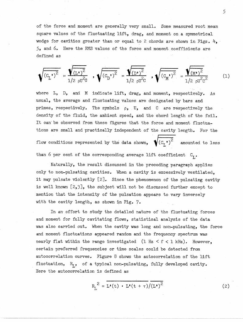
of the force and moment are generally very small. Some measured root mean
square values of the fluctuating lift, dl'ag, and moment on a symmetl'ical
wedge for cavities greater than or equal to 2_ chordsB,re shown in_ Figs. 4, 5, and 6. Here the RMS values of the force and moment coefficients are
defined as
whel'e 1, D, and M indicate lift, drag, and moment, respectively. As
.usual, the average and fluctuating values are designated by bars and
prL"l1eS, respectively. The symbols p, U, and C are respectively the
density of the fluid, the ambient speed, and the chord length of the foil.
It can be observed from these figures that the force and moment fluctua
tions are small and practically independent of the cavity length. For the
flow conditions represented by the data shown,~\C1,)2 amounted to less
than 6 per cent of the corresponding average lift coefficient C1 •
Naturally, the result discussed in the preceding paragraph applies
only to non-pulsating cavities. When a cavity is excessively ventilated,
it may pUlsate violently [2J. Since the phenomenon of the pulsating cavity
is well known [2,3J, the subject will not be discussed further except to
mention that the intensity of the pulsation appears to vary inversely
with the cavity length, as shown in Fig. 7.
In an effort to study the detailed nature of the fluctuating forces
and moment for fully cavitating flows, statistical analysis of the data
was also carried out. When the cavity was long andnoh"'pulsating, the force
and moment fluctuations appeared random and the frequency spectrum was
neal'ly flat within the range investigated (1 Hz < f < 1 kHz). However,
certain prefel'red frequencies or time scales could be detected from
autocorrelation curves. Figure 8 shows the autocorrelation of the lift
fluctuation, 11" of a typical non-pulsating, fully developed cavity.
Here the autocol'relation is defined as
---_._-------._._-------_.
5
(1)
(2)

6
where L' is the fluctuating component of the lift and 1" is the delay
time. The scale factor of 64 on the abscissa is the ratio of the tape
speeds during analysis and recording. For the particular case shown in
this figure there are two characteristic frequencies, 14 Hz and 284Hz.
The lower frequency appears to be associated with the natural frequency of
the cavitating flow, although it was extremely weak and difficult to detect
for longer cavities. The second characteristic frequency is more readily
detectable and is identifiable as that related to a natural frequency of
the hydroelastic system. No new information could be obtained from cross
correlations among lift, drag, and moment. The autocorrelation curve of a
pulsating cavity, obtainable by increasing the rate of air ventilation into
the same cavity which Fig. 8 represents, is shown in Fig. 9. Clearly, the
characteristic frequency of the pulsating cavity, 26 Hz in this case, is
unrelated to those of non-pUlsating cavities.
B. Partial Cavities
As compared to its fully developed counterpart, a partial cavity was
found to be considerably more unstable as a rule. Moreover, since part of
the surface profi.le on the cavity side of the foil may be wet, the hydrofoil
shape may complicate the problem. Experiments were carried out using mainly
the symmetrical wedge shown in Fig. 2(a) and the modified wedge shown in
Fig. 2(b). The break in the surface profile of the second wedge appeared
to cause vibration when the cavity was short; this will be discussed in more
detail later.
As has been observed by others [4,5,6,7J, very severe vibration occurs
quite frequently when the cavity is approximately equal to one chord. In
fact, this type of vibration is so common that it is rather difficult to
avoid. A typical plot of the relative RMS values of the fluctuations (lift,
drag, and moment) normalized with the respective maximum values, as shown in
Fig. 10, exhibits a peak intensity at ~/C ~ 1. The vibration at ~/C ~ 1
is not unavoidable, however. Using a relatively stiff system it was found
possible to have flow at ~/C ~ 1 without severe vibration, at least for
the case of a symmetrical wedge at a relatively small angle of attack.
Figure 11 shows that in this case the RMS values are relatively flat over
the entire region without an apparent peak at~/C = 1. Frequency spectrum

analysis of the fluotuation further revealed the concentration of energy at
a certain frequency whioh changed with the cavity .l~ngth.
Three types of instabilities were observed to exist in addition to
the ever-present random vibrations. Because of high energy concentrations
these vibrations are of practioal importance and should be studied in
detail. Further experimental and analytical evidenoe ooncerning the three
major instabilities is discussed in the following seotion.
1. Natural Frequency of Partial Cavities
Unlike the fully developed oavities, short cavities produoe rather
severe vibrations at certain frequencies. The intensity of these vibra
tions is so large that they are readily recognizable even on unfiltered
oscillographic records. Figure 12 is typical of'such a record wherein a
large-amplitude vibration believed to be caused by the hydrodynamic in
stability of the cavitating flow can be noted.' A more precise determina
tion of the frequency associated With the vibration was obtained by means
of frequency spectrum analysis. In general, large and well-defined peaks
existed in the frequency spectrum of a short cavity because the three types
of instabilities mentioned previously could be made to occur at frequencies
sufficiently far apart.
As was reported by Besch [7J, the fundamental frequency of th~ vibra
tion depends primarily on the cavity length, but not 'on the elasticity of
the spring system. Figure 13 shows the functional relationship between
the reduced frequency, k ~ and the dimensionless cavity length. Here o the reduced frequency is defined as
f C o k =-U o
where f is the fundamental frequency of the vibration. Included in this o
figure are also the data shown in Fig. 25 of Besch's report [7J and those
of Kaplan and Lehman [6J. The correlation is good considering the inac
curacy involved in the cavity length measurement and the large differences
which existed among the three experimental set-ups, For example, the
natural frequencies of the elastic system used in this experiment are at
least ten times as great as in that of Besch, whereas the foil was only
7

8
about one-third as large as Besch's. Clearly, a cavity flow is basically
unsteady and oscillates at a characteristic frequency which is a function
of cavity length and flow speed.
The frequency spectrum analysis also provided a rough estimate of
the amplitude of the vibration at the natural frequency of the cavity_
Figure 14 shows the amplitude in volts as a function of the relative
cavity length. No attempt was made to relate the voltage output to the
real physical quantities because of the questionable accuracy involved in
this particular case. The figure is intended to show only the general
trend that the amplitude is largest when the average cavity length is
nearly equal to one.
2. Two Types of Flutter-Like Vibrations
As was noted by Besch [7J, the signals from lift and moment trans
ducers often contained more than one frequency component of large-ampli
tude oscillations. However, practically no attention has been given by
previous investigators to the significance of these vibrations. In most
cases they have not even recognized the differences between these phe
nomena, which are primarily hydroelastic, and other types of vibration,
which are primarily hydrodynamic.
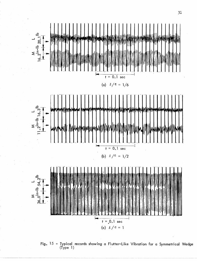
Typical oscillographic records taken for a symmetrical wedge for
three average cavity lengths~-t/C ~ 1/6, 1/2, and l--are shown in Fig. 15.
Nearly sinusoidal vibrations in the neighborhood of 315 Hz in both lift
and moment are clearly shown for all three cases. It is significant that
the reduced frequency, as shown in Fig. 16, is nearly independent of the
cavity length but appears to vary with the stiffness of the supporting
springs. Furthermore, the frequency of the vibration is of the same
order of magnitude as the system's coupled primary frequency, denoted
f l ' in Fig. 16, but an order of magnitude greater than the natural fre
quency of the cavity previously discussed. The amplitude of the vibra
tion, however, is strongly dependent on the cavity length. Generally, as
the cavity length increases, the amplitude first decreases to a minimum
at around mid-chord and then increases to a maximum at around one chord, as
clearly suggested by the records shown in Fig. 15. In some cases, however,
the amplitude decreases monotonically with the cavity length and fails to

9
have a severe vibration when the cavity length is equal to one chord. Rela
tively stable flow is likely to oCQur for a symmetrical wedge a,t small attack
angles with relatively stiff torsional restraint. Indeed, for some experi
ments it appeared that the critical flutter speed might have been obtained.
Because of the time limitation and other factors to be discussed later, no
precise determination of the flutter boundary was obtained. For the sym
metrical wedge at a 5-degree attack angle and a one-chord cavity length, the
critical flutter speed, U/wC, appeared to be in the neighborhood of 0.08
(an order of magnitude smaller than that computed by Besch). If the phe
nomenon could be shown to be classical flutter, then the critical flutter
,speed would have to be very sensitive to the attack angle, the surface
profile, and the point of separation.
Using the present elastic system it was not possible to obtain a
stable flow for the non-symmetrical wedge shown in Fig. 2(b) at a 5-degree
attack angle when the flow separated from the leo9.dingedge. Contrarily, a
limited number of experiments carried out for the type of foil shown in
Figs. 2(c) and 2(d), wherein separation was forced to occur at a small
distance downstream of the leading edge, failed to produce any vibration
of the type discussed herein. However, severe vibrations occurred as soon
as the separation point moved back to the leo9.ding edge while all other
variables were kept practically unchanged. This strong influence of the
separation point on the critical flutter speed has o9.lso been reported [8J
for the case of supercavitating hydrofoils.
A second type of vib:r.o9.tion was found to occur when the non-symmetrical
wedge, Fig. 2(b), was tested. It Wo9.S also a neo9.rly sinusoidal vibration,
o9.S shown in Fig. 17. As with the other flutter-like vibration, the fre
quency was independent of the cavity length, but the amplitude varied
considerably with the cavity length. Fortunately, the two types of flut
ter-like vibro9.tions 'W'ere readily distinguishable because the last type
vibrated at a higher frequency (about 500 Hz). Furthermore, the amplitude
varied in such a way that the maximum occurred when the cavity length was
approximately equal to 0.4 chord.
Figure 18 illustrates the fact that the reduced frequency of the
vibration is independent of the cavity length, but dependent on the stiff
ness of the system (natural frequency in the second mode, f2" in this

10
case) • As might be observed from the typical records presented in Figs'.
15 and 17, the two types of vibrations are of different modes. This is
clearly seen in Fig. 19, where the amplitude ratio,
Cl\ A* = 1\r
is plotted for the two types of vibrations. Here AL and 1\r repre
sent, respectively, the amplitude of the lift and the moment. It is
also interesting to compare the frequency ratio, f l /f2, of the two
types of vibration with that of the two fundamental frequencies of the
system in air, f l '/f2 ', as shown in Fig. 20. Data taken for the non
symmetrical wedge for which both fl and f2 existed are shown as
circles in this figure. Included in the same figure also are similar
data for the symmetrical wedges of different masses. Since there was
(4)
no f 2-type vibration for the symmetrical wedges, the corresponding val
ue of f2 for the non-symmetrical wedge was used to calculate
the ratio f l /f2• It is noteworthy that straight lines of slope one
can be drawn to represent the data in this figure.
All: the evidence discussed above strongly suggests that the vibra
tions were flutter--self-excited vibration in a natural mode of the sys
tem. The occurrence of these vibrations, however, is strongly influenced
by many factors, such as surface profile, angle of attack, and cavity
length. This is a complication due to the cavity reattachment, which is
not present in supercavitating flows. Analytical prediction of the crit
ical flutter speed surely would be very difficult. It appears only
natural that Besch [7J has found no agreement between data and a theory
which was rough and at best represented only the flow about a flat plate.
It may also be of interest to point out that the natural frequencies of
the system used in Besch's water tunnel experiment were too close to the
natural frequencies of the cavities to permit easy identification of the
basically different phenomena. In fact, a careful inspection of the data
presented in Figs. 25 and 27 of Ref. [7J reveals the existence of flutter
like vibration when the cavity was nearly one chord long.
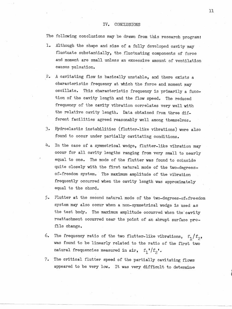
IV. CONCLUSIONS
The following conclusions may be drawn from this research program:
1. Although the shape and size of a fully developed cavity may
fluctuate substantially, the fluctuating components of force
and moment are small unless an excessive amount of ventilation
causes pulsation.
2. A cavitating flow is basically unstable, and there exists a
characteristic frequency at which the force and moment may
oscillate. This characteristic frequency is primarily a func
tion of the cavity length and the flow speed. The reduced
frequency of the cavity vibration correlates very well 'with
the relative cavity length. Data obtained from three dif
ferent facilities agreed reasonably well among themselves.
3. Hydroelastic instabilities (flutter-like vibrations) were also
found to occur under partially cavitating conditions.
4. In the case of a symmetrical wedge, flutter-like vibration may
occur for all cavity lengths ranging from very small to nearly
equal to one. The mode of the flutter was found to coincide
quite closely with the first natural mode of the two-degrees
of-freedom system. The maximum amplitude of the vibration
frequently occurred when the cavity length was approximately
equal to the chord.
5. Flutter at the second natural mode of the two-degrees-of-freedom
system may also occur when a non-symmetrical wedge is used as
the test body. The maximum amplitude occurred when the'cavity
reattachment occurred near the point of an abrupt surface pro
fi le change.
6. The frequency ratio of the two flutter-like vibrations, f l /f2,
was found to be linearly related to the ratio of the first two
natural frequencies measured in air, f l t /f2t •
7. The critical flutter speed of the partially cavitating flows
appeared to be very low. It was very difficult to determine
11

12
the critical flutter speed because it appeared to be sensitive to
the surface profile. the angle of attack, and the point of separa
tion.
8. The existing theory is not accurate enough to predict flutter of
partially cavitating foils. A theory taking into account the
separation and the reattachment condition with considerable pre
cision is probably needed.
9. Further experiments using a system permitting greater and more
precise variation of the hydroelastic and hydrodynamic variables
are needed for complete understanding of the problem.

-- -- -- -- -- -- -- -- --
13
LIST OF REFERENCES
[lJ Tulin, M. P., Steady Two-Dimensional Cavity Flows about Slender BodieS 2
David Taylor Model Basin Report 834, 1953.
[2J Silberman, E. and Song, C. S., "Instability of Ventilated Cavities," Journal of Ship Research, Vol. 5, No.1, June 1961.
[3J Song, C. S., "Pulsation of Ventilated Cavities," Journal of Ship Research, Vol. 5, No.4, March 1962.
[4J Meijer, M. C., "Some Experiments on Partly Cavitating Hydrofoils," International Shipbuilding Progress, Vol. 6, No. 60, 1959.
[5J Wade, R. B. and Acosta, A. J., "Experimental Observations on the Flow Past a Plano-Convex Hydrofoil," J. Eng. for Power, ASME, No. 65-FE3, 1965.
[6J
[7J Besch, Peter K., Flutter and Cavity-Induced Oscillation of a TwoDegree-of-Freedom Hydrofoil in Two-Dimensional Cavitating Flow,
. Naval Ship Research and Development Center, Department of the Navy, Report 3000, April 1969.
[8J Song, C. S. and Almo, John, An Experimental Study of the Hydroelastic Instability of Supercavitating Eydrofoils, University of Minnesota, st. Anthony Falls Hydraulic Laboratory Project Report No. 89, February 1967.


EIQQB:m§ (1 through 20)


1. Viewing Window
2. Air Intake for Tunnel Pressure Control
3. Plastic Housing for Spring System
4. Spring System
5. Venl'ilation Valve
Fig. 1 - A View of the Two-Dimensional Test Section of the Free-Jet Water Tunnel
17

18
(a) Simple Wedge
tE-.j . ~----I
(cf Stepped Wedge
r- 11i +-1-1/2"----1
I~ J
(b) Modified Wedge
cl=::-. ------,1 ~ 111 -)oi+-~ -1-1/211~
(d) Notched Wedge
Fig_ 2 - Cross-sectional Profiles of Test Bodies

19
~ '-"--~"-'i
t == 0.1 sec
(a) Lift and moment vibration
, '~
'" ~
I,Ji
1111
I
- .1 ,1 I .M. LI. lid
'T I Iii'
r ,. t! " i I I". M .. I-... I
I """----.. - ..• ~---.. -.. - .. - •• - .. ---j , t == 0.1 sec
(b) Predominantly I ift vibration
Fig. 3 - Typical record of Free-Vibration Test

8 x
tt ... .....
s:: .~ u E
CD 0
U ..... .... . -..J
0) . s:: .-.....
0 j ..... u j
u. .... 0
V')
~ IX
5 '---~-~---~I - r -~
;Lr= t =:j o a = 7-1/20
4r ~~ o a = 8-1/20 a c-';
3r 0 0
2 0 0 0 0 0
0 0 0 0 0
0 0
0 8
0Q' I I I I I I 2 4 6 :8' 10 12 1~
Cavity length in Chords, .t/C
Fig o 4 - RMS Values of Fluctuating Lift Coefficient for Fully Developed Cavities
--I:
16
N o

0 0
x
li ... ......
c Q)
u 4: ......
Q) o
U 0> o ....
Q
0> C
"'-o :::l ...... U :::l
u.. ...... o
V')
~ ~
-----,:--~"""
100 I -~-----------------,
008
006
0.4
I
0.2i
00
o
o
0 0
8 0
0 0
2 4
o
o
o
o
o
8
o a=7-1/2°
C a = 8-1/20
-"----', _______ ~ _____ __i_
6 - 8 10 12 14 Cavity length in Chords, ~/C
Figo 5 - RMS Values of Fluctuating Drag Coefficient for Fully Developed Cavities
16
N I-'
'I

0 0051 0
x
o.J ~ .. ....
s:: .~ 0.3" u tE
Q) 0
u .... s:: Q)
E 0 0.2~ ~ 0) c .... 0 :::l .... U :::l
LI- 0.1 t-~
0
Vl
~ 0:::
01 0
a = 7-1/2 0
a = 8-1/20
0 0 0
0 O· 0
0 [Q 0
0
0 0 DO 0
0
I I I ! I I I 2 4 6 8 10 12 14
Cavity length in Chords, l/C
Fig. 6 - RMS Values of Fluctuating Moment Coefficient for Fully Developed Cavities
16
!\) !\)

8 .-
>< ...J
U <1
... c:; 0 .-.... e I/)
:l I:l..
.... "-.,.. ...J
"-0
>.. .t I/) c:; CLl ....
..E'
12r-------~1--------~1------~,--------r-1----~
10 0 - -
0 Two-Dimensional Wedge
8 - ,-
0 0
0 6 - -
0
0
4 - 0 -
0
2 !- -
o ~------_I~----~_~I------_~I------_~I------~ o 0.1 0.2 0.3 0.4 0.5
Inverse of C~vity Length, CIl,
Fig. 7 .. Intensity of Cavity Pulsation as a function of Cavity Length for Ventilated Cavities
23

24-
100 ----
f ::; 284 Hz
o O~----------~--~1~-~'--------~----~2--------------~3 t)( 104/64 sec
1.0
0.5
f = 14 Hz
o o 3 2 ,. x 1 0 /64 sec
3
Fig. 8 - Autqcorrelation of FluctlJatlng. Lift of Non-Pulsating Cavity , ",
Ule = 2, a = 12°~ h = 0.690) v

u I
i o.
o II t-
0 0 -+
II
co -.0 • • 0 0
+ +
'lilt ~ 0 ~ • • • 0 0 0
+ + I
rr
'lilt -.c) co 0 • • 0 0
0 0 0 -I I • I
25
....
0
~ -.0
o o II
b :>
.. o ~ ,.... II c
o
.~ u.

26
lA--.--~--~------~--------T-~----~------~
1.2 ~~ tao·~
C . • u ....
Q)
.. 1.0 0
~ 0
0 ~
ti°.a
A .. 0
; 0 ::l 0.6 A ~ V) 0 ~ Q)
.~ 1; 0.4 Q) 0 Crl: B 0
0.2
Moment
0.4 0.8 1.2 1,,6
Cavity length in Chords, tiC
Fig_ 10 - Relative Intensity of -Fluctuation for Short Cavities

27
1.6
0
1.4
~1.2 0
tf . ~ 1.0
II)
Q) ;:)
o o o o 0
> '" ~
0~8 . Q)
.2: .... 0 Q)
~
0.6
0.4 0.8 1.2 2.0 . Cavity length in Chords, tiC
Fig. 11 - Relative Intensity of Fluctuating Lift of 'a Stable Cavity


0.6
-u 1- 0.5 ,-0 .::>
, ;:.... u c .. ::>
g- 0.4 L. '-
""0 II) u ::>
""0 II)
a::: 0.3
0.2
0.10•2
o
004
o o
o 00
0.6
o SAF-
-0 Besch In
D kaplan and Lehman 16]
0
0 0
0 0
0 0 B 0
BOO
o
0.8 1.0
Cavity length in Chords, .tIC
0
o o
L2
o 0° o
o 1..4
o
Fig. 13 - Natural Frequency of Short Cavities as a function of Cavity LenQth
1.6 N '-0

'" .... o > c
(J) -0 :J ....
0.2
~ 0 0 1 <
00•2 004 006
" "
0 0 8 LO 1.2 104
Average cavity length in Chords, tiC
1'..6 1.8
Fig. 14 - Relative Intensity of Self-Excited Cavity Vibration as a function of Cavity Length
2.0
\..V o
o '-0. r-
. ....-...0 'I I:
~.-~
....r-
...0 ~
-I ,.;
--
l(") .,..
...0 'I I:
~·-o ....
31
, ...... , .... ljiilllllUJWnflm'M
~~!! ~ I ~~~)! '1:\ :~ Iii ~ II if '~ I ill iii W ~i I
~=-:t_. __ .. _ ... ~ ~ ______ ._~---I t :::: 001 sec
(a) ~/c:::: 1/6
k--t :::: D. 1 sec
(b)~/c::::1/2
~------- . ---~----l t :::: .0.1 sec
(c) ~ / c :::: 1
Fig. 15 - Typical records show ing a FI utter-Like Vibration for a Symmetri cal Wedge (Type 1) .
32
6- f I
1 ::: 365 Hz
0 f I 1 == 310 Hz
3.0 0 f I = 255 Hz 1
2,,5
U I .::::> ...:::-
~ II 6 0
-::I. 2.0' 0 0 0 ...
0 >-" 0 u 0 c: Q) ::J 0" Q) ... 1.5 ....
"'tJ Q) U ::J
"'tJ Q) ~
1 .. 0 -L \
50
0.5
0.4 0.6 0.8 LO Cavity length in Chords, t Ie
Fig. 16 - Reduced Frequency of a Flutter-I ike Vibration, Type 1

...c -0-,
-I 0
1.0 C")
...c I c :::;! .;....1.0 -0
0
1.0
...c -0
-I 0
-0 C")
...c I c
:::;! '--0 0
1.0
----
-
-----
-
i-oIl .. ~--· .-~------~ t :::: 0 0 1 sec
(a) "/ c :::: 1/5
(b) "/ c :::: 2/5
I-I--------i t :::: 0.1 sec
t :::: O. 1 sec
Fig. 17 - A Typical Record of a Flutter-like Vibration (Type 2) for a Non-Symmetrical Wedge
33
34
405~~----~----~-T------~--------~------'-------~
6. f11 = 650 Hz
o fll = 610Hz 4.0 o fll = 575 Hz
305 0 6 6, . 6,
0 0,: I :::> 0 0
..... C'l 0 0 0
II 3.0 0 C'l
.~
.. >. 0 c CI) :::l
~ 205 ..... "'0
CI) 0
~ :::l
--L "'0 CI)
0::
2.0 \ ~ 50
1.5
0.2 0.4 0.6 0.8 1.0
Cavity length in Chords, t / c .
Fig. 18 - Reduced Frequency of a Flutter-Like Vibration, Type 2

12.5~i ------.------,-------r------~----~------I
10
-JI ~ « « u II
'" 7.5
« .~ .... c .... Q)
5~ "'C :::> .... a.. E «
I 2.5
00
6
0
0.2
6 Type 2 v ibrati on
0
o Type 1 vibration
0.4 0.6 Cavity length in Chords r
0.8 tiC
6
0
1.,0
Figo 19 - Amplitude ratio of Flutter-I ike Vibrations
0
1.2
'v) \.n

N O•8
'--......
c:: 0
I .--0 "- 0.7
1 -8 > ...... 0 on CI) a... >-..... 0 0.6 ~
CI) ..s:: .... ...... 0
0 0.5 '.0: 0
0=::
>-U c:: Q) ::)
0" CI) ...
0.40 •2 u..
0
.D.
/ 0 //
0.3 0.4 0.5 0.6
Ratio of Two Fundamental Frequencies of System in Air
Fig. 20 - Comparison of Frequency Ratios
-'
-brass
0.7 f Ilf I 1 2
::oJ
0.8
\...V 0'..

Copies
DISTRIBUTION LIST FOR PROJECT REPORT NO. 111
of the St. Anthony Falls Hydraulic Laboratory
Organiz,ation
37
40 Commander, Naval Ship Research and Development Center, Washington, D,C. 20007, Attn:
39 ~ Code un 1 - Code 513
2 Commanding Officer, Naval Ship Research and Development Laboratory, Annapolis, Maryland 21402, Attn: Library
·2 Commanding Officer, Naval Ship Research and Development Laboratory, Panama City, Florida 32402, Attn: Library
5 Commander, Naval Ship Systems Command, Department of the Navy, Washington, D. C. 20360, Attn:
1 _ Code 0342 DEF 3 - Code 2052 1 - Code 03412
20 Director, Defense Documentation Center, 5010 Duke Street, Alexandria, Virginia 22314
1 Chief of Naval Research, Department of the Navy, Washington, D. c. 20360, Attn: Mr. Ralph D. Cooper, Code 438
1 Director, Office of Naval Research Branch Office, 495 Summer Street, Boston, Massachusetts 02210
1 Director, Office of Naval Research Branch Office, 219 S. Dearborn Street, Chicago, Illinois 60604
1 Office of Naval Research Resident Representative, 207 West 24th Street, New York, New York 10011
1 Chief Scientist, Office of Naval Research Branch Office, 1030 East Green Street, Pasadena, California 91101
1 Director, Office of Naval Research Branch Office, 50 Fell Street, San Francisco, California 94102
3 Director, Naval Research Laboratory, Washington, D. C. 20390, Attn: Library, Code 2029 (ONRL)
1 Commander, Naval Facilities Engineering Command, Department of the Navy, Washington, D. C. 20390, Attn: Code 0321 BCDE

38
Copies Organization
4 Commander f Naval Ship Engineering Center, Department of the Navy, Center. Building, Prince Georges Center, Hyattsville, Maryland 20782, Attn:
1 - Code 6110 1 - Code 6ll4D 1 - Code 6136 1- Code 6140 ADEF
1 Strategic Systems Projects Office, Department of the Navy, Washington, D.C. 20360, Attn: Dr. John Craven (NSP-OOl)
1 Commanding Officer, Naval Air Development Center, Johnsville,Warminster, Pa. 18974, Attn: Technical Library
1 Commanding Officer and Director, Naval Applied Science Laboratory, Flushing and Washington Avenues, Brooklyn, New York 11251
1 Commander, Naval Electronics Laboratory Center, San Diego, California 92152, Attn: Library DEF
1 Director (Code 2027), Naval Research Laboratory, Washington, D. C. 20390
1 Commanding Officer, Navy Underwater Weapons Research and Engineering Station, Newport, Rhode Island 02840
1 Commander, Naval Oceanographic Office (Library), Department of the Navy, Washington, D. C. 20390 BEF
1 Commander, Naval Proving Ground, Dahlgren, Virginia 22448, Attn: Technical Library BDE
1 Commanding Officer and Director, Naval Civil Engineering Laboratory, Port Hueneme, California 93401, Attn: Code L3l DE
1 Commander, Boston Naval Shipyard, Boston, Massachusetts 02129, Attn: Technical Library
1 Commander, Charleston Naval Shipyard, Naval Base, Charleston, South Carolina 29408, Attn: Technical Library
1 Commander, Norfolk Naval Shipyard, Portsmouth, Virginia 23709, Attn: Technical Library
1 Commander, Pearl Harbor Naval Shipyard, Box 400, Fleet Post Office, San Francisco, California 96610, Attn: Code 246-p
1 Commander, Portsmouth Naval Shipyard, Portsmouth, N.H. 03801, Attn: Technical Library
1 Commander, Puget Sound Naval Shipyard, Bremerton, Washington 98314, Attn: Engineering Library

Copies Organization
2 Commander, San Francisco Bay Naval Shipyard, Vallejo, California 949.52, Attn:
1 .... Techmical Library 1 - Code 2.50
1 AFFDL (FDDS - Mr. J. Olsen), Wright-Patterson AFB, Dayton, Ohio 4.5433 BDE
1 NASA Scientific and Technical Information Facility, P.O. Box 33, College Park, Maryland 20740
1 Library of Congress, Science and Technology Division, Washington, D.C. 20.540
1 U.S. Coast Guard, 1300 E Street N.W., Washington, D. C. 20.591, Attn: Division of Merchant Marine Safety
39
1 . Director, Waterways Experiment Station, Box 631, Vicksburg, Mississippi 39180, Attn: Research Center Library BDE
1 Commandant (E), U.S. Coast Guard (Sta .5-2), 1300 E Street N.W., Washington, D.C. 20.591
1 University of Bridgeport, Bridgeport, Connecticut 06602, Attn: Prof. Earl Uram, Mech. Engl'. Dept. ABDE
4 Naval Architecture Department, College of Engineering, University of California, Berkeley, California 94720, Attn:
1 - Librarian 1 - Prof. J. R. Paulling 1 Prof. J. V. Wehausen 1 - Dr. H. A. Schade
3 California Institute of Technology, Pasadena, California 91109, Attn: 1 - Dr. A. J. Acosta. ABDE 1 - Dr. T. Y. Wu 1 - Dr. M. S. Plesset BDE
1 University of Connecticut, Box U-37, Storrs, Connecticut 06268, Attn: Prof. V. Scottron, Hydraulic Research Lab DE
1 Cornell University, Graduate School of Aerospace Engr., Ithaca, New York lLj,8.50, Attn: Prof. W. R. Sears
1 Harvard University, 2 Divinity Avenue, Cambridge, Massachusetts 02138 Attn: Prof. G. Birkhoff, Dept. of Mathematics DE
1 University of Illinois DE, College of Engineering, Urbana, Illinoj_s 61801, Attn: Dr. J.M. Robertson, Theoretical and Applied Mechanics Dept.
1 The University of Iowa, Iowa City, Iowa .52240, Attn: Dr. Hunter Rouse

40
Copies Organization
2 The University of Iowa, Iowa Institute of HYdraulic Research, Iowa City, Iowa 52240, Attn:
1 - Dr. L. Landweber 1 - Dr. J. Kennedy
1 Kansas state University DE, Engineering Experiment Station, Seaton Hall, Manhattan, Kansas 66502, Attn: Prof. D. A. Nesmith
1 Lehigh University DE, Bethlehem, Pennsylvania 18015, Attn: Fritz Laboratory Library
1 Long Island University, Graduate Department of Marine Science, 40 Merrick Avenue, East Meadow, N.Y. 11554, Attn: Prof. David Price
1 Massachusetts Institute of Technology, Hydrodynamics Laboratory, Cambridge, Massachusetts 02139, Attn: Prof. A. T. Ippen DEF
5 Massachusetts Institute of Technology, Department of Naval Architecture and Marine Engineering, Cambridge, Massachusetts 02139, Attn:
1 - Dr. A. H. Keil 1 - Prof. P. Mandel ADE 1 - Prof. J. R. Kerwin 1 - Prof. P. Leehey DEF 1 - Prof. M. A. Abkowitz ABCDE
3 University of Michigan, Department of Naval Architecture and Marine Engineering, Ann Arbor, Michigan 48104, Attn:
1 - Dr. T. F. Ogilvie 1 - Prof. H. Benford 1 - Dr. F. C. Michelsen
5 st. Anthony Falls HYdraulic Laboratory, University of Minnesota, Mississippi River at 3rd Ave. S.E., Minneapolis, Minnesota 55414, Attn:
1 - Director 1 - Dr. C. C. S. Song 1 - Dr. J. M. Killen BDEF 1 - Mr. F. Schiebe DEF 1 - Mr. J. M. Wetzel DE
1 U.S. Naval Academy, Annapolis, Maryland 21402, Attn: Library
1 U.S. Naval Postgraduate School, Monterey, California 93940, Attn: Library
1 New York University, University Heights, Bronx, New York 10453, Attn: Prof. W. J. Pierson, Jr.
2 New York University, Courant Institute of Mathematical Sciences DE, 251 Mercier Street, New York, New York 10012, Attn:
1 - Prof. A. S. Peters 1 - Prof. J. J. Stoker

~
,
Copies Organization
1 University of Notre Dame, Notre Dame, Indiana 46556, Attn: Dr. A. Strandhagen BDE
1 The Pennsylvania state University, Ordnance Research Laboratory, University Park, Pennsylvania 16801, Attn: Director ABDE
1 Colorado state University, Department of Civil Engineering, Fort Collins, Colorado 80521, Attn: Prof. M. Albertson BDEF
3 stanford University, Stanford, California 94305, Attn:
41
1 ... Prof. H, Ashley, Dept. of Aeronautics and Astronautics DE 1 - Prof. R. L. Street 1 - Prof. B. Perry, Dept. of Civil Engr.
3·· stevens Institute of Technology, Davidson Laboratory, 711 Hudson Street, Hoboken, New Jersey 07030, Attn: Dr. J. Breslin (3)
1 Aerojet-General Corporation, 1100 W. Hollyvale Street, Azuza, California 91702, Attn: Mr. J. Levy, Bldg. 160, Dept. 4223
1 Bethlehem Steel Corporation, Central Technical Division, Sparrows Point Yard, Sparrows Point, Maryland 21219, Attn: Mr. A. Haff, Technical Mgr.
1 Cornell Aeronautical Laboratory, Applied Mechanics Department, P.O. Box 235, Buffalo, New York 14221, Attn: Dr. 1. statler BDE
1 Electric Boat Division, General Dynamics Corporation, Groton, Connecticut 06340, Attn: Mr. V. Boatwright, Jr.
1 General Applied Sciences Laboratories, Inc. DEF, Merrick and Stewart Avenues, Westbury, L.I., New York 11590, Attn: Dr. F. Lane
1 Gibbs and Cox, Inc., Technical Information Control Section, 21 West Street, New York, New York 10006
1 Grumman Aircraft Engj.neering Corp., Bethpage, L. 1., N.Y., 11714, Attn: Mr. W. Carl
2 Hydronautics, Inc., Pindell School Road, Howard County, Laurel, Maryland 20810, Attn:
1 - Mr. P~ Eisenberg 1 ... Mr. M. Tulin
1 Lockheed Missiles and Space Company AE, P.O. Box 504, Sunnyvale, California 94088, Attn: Mr. R. L. Waid, Facility No.1, Dept. 57-01, Bldg. 150
2 McDonnell Douglas Aircraft Company, Douglas Aircraft Division DE, 3855 Lakewood Boulevard, Long Beach, California 90801, Attn:
1 - Mr. John Hess 1 - Mr. A. M. O. Smith

42
Copies Organization
1 National Science Foundation1 Engineering Division1 1800 G Street N.W., Washington, D. C. 205501 Attn: Director DE
1 Newport News Shipbuilding and Dry Dock Company, 4101 Washington Avenue 1 Newport News, Virginia 236071 Attn: Technical Library Dept.
1 Oceanics, Incorporated1 Technical Industrial Park, Plainview, L.I' 1 N.Y. 11803, Attn: Dr. Paul Kaplan
1 Robert Taggart, Inc., 3930 Walnut Street, Fairfax, Virginia 22030, Attn: Mr. R. Taggart
1 Sperry-Piedmont Company, Charlottesville1 Virginia 229011 Attn: Mr. T. Noble
1 Society of Naval Architects and Marine Engineers 1 74 Trinity Place, New York, New York 10006
2 Southwest Research Institute BCDEF1 8500 Culebra Road1 San Antonio, Texas 78206, Attn:
1 - Dr. H. Abramson 1 - Applied Mechanics Review
1 Naval Ship Engineering Center, Norfolk Division, Boat Engineering Department, Norfolk, Virginia 23511, Attn: Mr~ D. L. Blount, Code 6660
1 Prof. Jerome Lurye, Department of Mathematics1 St. John's University ABCDE1 Jamaica, New York 11432
1 Stanford Research Institute, Menlo Park, California 94025, Attn: Library
1 Dr. Roland W. Jeppson BDE, College of Engineering, Utah State University, Logan, Utah 84321

Unclassifie<3, Security Classification
DOCUMENT CONTROl.. DATA· R&D (Security dasslflcation of title, body of abstract and Indexing annotation must be enterl;>d wh~n the ov<>rall report Is dasslfiedJ
1. ORIGINATING ACTIVITY (Corporatl;> author) ~". R~PORT S~CURITY CI-ASSIFICATION
St. Anthony Falls Hydraulio Laboratory Unclassified University of Minnesota 2b. GROUP
3. R~PORT TITI-.~
VIBRATION OF CAVITATING HYDROFOILS
4. P~SCRIPT1Vf;: NOTf;:S (Type of report and.inplu~lve dif4tes)
Final Report - October 1, 1967 to June 30, 1969 5. AUTHORIS) (First naml', midr1lfJ Inlital, IM'tnamr»
Charles C. S. Song
6. RIOPORT r;>ATf;: 7a. TOTAl-. NO. OF PAGIOS 17b. NO. O~ Rf;:PS
October 1969 36 8a. CONTRAcT OR GRANT NO. 9a. O'RIGINATOR'S RIOPORT NUM13IOR(S)
Nb001~-67-A-0113-0005 b. PROJIOCT NO. Project Report No. 111 SF 013 02 01
c. 9b. OTHIOR REPORT NO(S) (Any other numbers that may be assigned thi I' report) ,
d.
10. PISTRI13UTION STATf;:Mf;:NT
,This document has been approved for public release and sale; its distribution is unlimited.
11. SUPPI-~MIONTARY NOTf;:s 12. SPONSORING MII-ITARY ACTIVITY
Naval Ship Research and Development Center Washington, D. C. 20007
13. A13STRACT
A primarily experimental research program has been carried out using a free-jet water tunnel for the purpose of studying force and moment fluctuations on cavitating two-dimensional hydrofoils. Both a sYmmetrical wedge and· a non-symmetrical wedge were tested for a wide 'range of cavity lengths and several different elastic conditions. Fluctuations in lift and moment were of primary concern in the experiments.
It was revealed that the force and moment were quite steady if the cavity was longer than two chords unless an excessive amount of ventilation caused cavity pUlsations. For a shorter cavity, however, the flow was generally very unstable, and severe vibrations were noted. A cavity of any length was found to be basically unstable and to oscillate at a characteristic fr€quency which was primarily a function of the cavity length. The vibrating cavity may cause an elastically supported foil to vibrate severely when the cavity is short. The largest-amplitude vibration often occurred when the cavity length was approxi-mately equal to one chord. Flutter-like vibrations were observed in the first and second natural modes of the two-degree-of-freedom system. The frequency of these vibrations Was found to be practically independent of the cavity length. The severest vibration in the first natural mode usually occurred when the average velocity length was approximately equal to a chord, whereas vibration in the second natural mode was found more likely to occur when the cavity was very short.
DO ,F~oR~6514 73 (PAGE 1) . Unclassified
SIN 0101-807-6811 Security Classification A- 31408

Unclassified Security Classification
14. LINK A LIN K B l.INK C K gy WORDS
ROLE WT ROLE WT ROL e: WT
Hydrofoil, cavitating foils
Flutter, vibrating foils
Vibrating cavities, hydroelasticity
Instability of cavities
Unclassified SIN 0101-807-6821 Security Classification A-31409