vibration suppression of heavy vehicle chassis of … · 2016-09-09 · traction that enables the...
TRANSCRIPT

International Journal of Scientific & Engineering Research, Volume 5, Issue 8,August-2014 1079 ISSN 2229-5518
IJSER © 2014 http://www.ijser.org
VIBRATION SUPPRESSION OF HEAVY VEHICLE CHASSIS OF COMPOSITE STRUCTURE USING ANSYS
Mr. Bairy Ravinder N. Prashanthi P G Student, Department of Mechanical Engineering
ABSTRACT
High-technology structures often have stringent requirements for structural dynamics. Suppressing vibrations is crucial to their performance. Passive damping is used to suppress vibrations by reducing peak resonant response. Viscoelastic damping materials add passive damping to structures by dissipating vibration strain energy in the form of heat energy. The incorporation of damping materials in advanced composite materials offers the possibility of highly damped, light-weight structural components that are vibration-resistant.
The aim of the project is to analyze the heavy vehicle chassis without damping material and with damping material, damping material is hard rubber. The materials for heavy vehicle chassis are steel, carbon Epoxy and E – Glass Epoxy. The Static structural analysis is done to verify the strength of the heavy vehicle chassis and compare the results for three materials.
We are conducting analysis with the different number of layers 3, 5,11with in the limit of same thickness. Modal analysis is also done on the heavy vehicle chassis to determine mode shapes. In this project vibrations are reduced by using above materials in number of layers. Software used for modeling is Pro/Engineer and for analysis is ANSYS.
KEYWORDS: Chassis frame, Carbon Epoxy, E-Glass Epoxy, Structural analysis.
1.0 INTRODUCTION
A chassis consists of an internal framework that supports a man-made object. It is analogous to an animal's skeleton. An example of a chassis is the under part of a motor vehicle, consisting of the frame (on which the body is mounted) with the wheels and machinery.
Automotive chassis is a skeletal frame on which various mechanical parts like engine, tires, axle assemblies, brakes, steering etc. are bolted. The chassis is considered to be the most significant component of an automobile. It is the most crucial element that gives strength and stability to the vehicle under different conditions. Automobile frames provide strength and flexibility to the automobile.
Automotive chassis is considered to be one of the significant structures of an automobile. It is usually made of a steel frame, which holds the body and motor of an automotive vehicle. More precisely, automotive chassis or automobile chassis is a skeletal frame on which various mechanical parts like engine, tires, axle assemblies, brakes, steering etc are bolted. At the time of manufacturing, the body of a vehicle is flexibly molded according to the structure of chassis.
The automotive chassis provides the strength necessary to support the vehicular components and the payload placed upon it. The suspension system contains the springs, the
shock absorbers, and other components that allow the vehicle to pass over uneven terrain without an excessive amount of shock reaching the passengers or the cargo. The steering mechanism is an integral portion of the chassis, as it provides the operator with a means of controlling the direction of travel. The tyres grip the road surface to provide good traction that enables the vehicle to accelerate, brake, and make turns without skidding.
Automobile chassis is usually made of light sheet metal or composite plastics. The different types of automobile chassis include.
a) Ladder Chassis: Ladder chassis is considered to be one of the oldest forms of automotive chassis or automobile chassis that is still used by most of the SUVs till today. As its name connotes, ladder chassis resembles a shape of a ladder having two longitudinal rails inter linked by several lateral and cross braces.
b) Backbone Chassis: Backbone chassis has a rectangular tube like backbone, usually made up of glass fibre that is used for joining front and rear axle together. This type of automotive chassis or automobile chassis is strong and powerful enough to provide support smaller sports car. Backbone chassis is easy to make and cost effective.
c) Monocoque Chassis: Monocoque Chassis is a one-piece structure that prescribes the overall shape of a vehicle. This type of automotive chassis is manufactured by welding floor pan and other pieces together. Since monocoque chassis is cost effective and suitable for robotised production, most of the
IJSER

International Journal of Scientific & Engineering Research, Volume 5, Issue 8,August-2014 1080 ISSN 2229-5518
IJSER © 2014 http://www.ijser.org
vehicles today make use of steel plated monocoque chassis.
2.0 STRUCTURAL ANALYSIS
Static analysis calculates the effects of steady loading conditions on a structure, while ignoring inertia and damping effects, such as those caused by time-varying loads. A static analysis, however, includes steady inertia loads (such as gravity and rotational velocity), and time-varying loads that can be approximated as static equivalent loads. (such as the static equivalent wind and seismic loads commonly defined in many building codes).
2.1 LOADS IN A STRUCTURAL ANALYSIS
Static analysis is used to determine the displacements, stresses, strains, and forces in structures or components caused by loads that do not induce significant inertia and damping effects. Steady loading and response conditions are assumed; that is, the loads and the structure's response are assumed to vary slowly with respect to time. The kinds of loading that can be applied in a static analysis include:
Externally applied forces and pressures
Steady-state inertial forces (such as gravity or rotational velocity)
Imposed (non-zero) displacements, Temperatures (for thermal strain) ,Fluencies (for nuclear swelling)
2.2 MATERIAL PROPERTIES
Sl. No.
Properties
Units
Steel Carbon Epoxy
E-Glass Epoxy
Rubber
1 Young’s Modulus E11
N/mm2
2.068e11
1.34e 11
50 e
9
4
2 Density kg/ m3 7830 1600 2000 2466
3 Poisson Ratio - 0.3 0.3 0.3 0.49
2.3 DEFLECTION AND STRESS CALCULATIONS OF MAIN CHANNEL
L =total length of channel=7000mm, W=load on both channels=10,000kg ,(i.e) on one channel w=5000kg
• Reaction
R =
R = 1.71
Applying load at a distance of mid (i.e) 3500mm
• Bending moment
Mmax =
Mmax =
Mmax = 3.00431 Nmm
• Moment of inertia
I =
I =
I = 14119136 mm4
• Deflection
Y =
For Alloy Steel
E = 206800Mpa
Y =
Y = 12.23mm
• For Carbon Epoxy
E = 181000Mpa
Y =
Y = 13.98mm
• For E-lass epoxy
E = 38600 Mpa
Y = , Y = 65.55mm
Radius of gyration =
=
R.G = 82.23mm
IJSER

International Journal of Scientific & Engineering Research, Volume 5, Issue 8,August-2014 1081 ISSN 2229-5518
IJSER © 2014 http://www.ijser.org
Area =bd – h(b-t) = 70 X 220 – 208 (70-6) = 2088 mm2
• Modulus of section
Z =
Z = = 128355.7818
Shear force = 50 X 9.81 = 490.5N
Shear stress = =
Shear stress = 0.2349N / mm2
Stress at critical point = =
X 9.81 = 334.373N/mm2
Stress at critical point = =
X 9.81 = 668.746N/mm2
3.0 STRUCTURAL AND MODAL ANALYSIS OF CHASSIS
WITHOUT DAMPING MATERIAL AND LAYERS
3.1 STEEL
DISPLACEMENT
STRESS
SHEAR STRESS IN XY
3.2 CARBON EPOXY
DISPLACEMENT
STRESS
IJSER

International Journal of Scientific & Engineering Research, Volume 5, Issue 8,August-2014 1082 ISSN 2229-5518
IJSER © 2014 http://www.ijser.org
SHEAR STRESS IN XY
3.3 E - GLASS EPOXY
DISPLACEMENT
STRESS
SHEAR STRESS IN XY
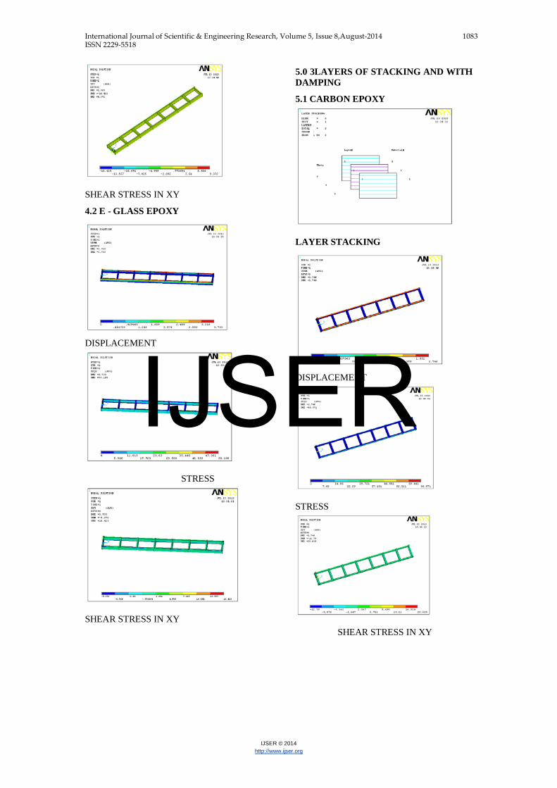
4.0 3LAYERS OF STACKING AND WITHOUT DAMPING
4.1CARBON EPOXY
LAYERSTACKING
LAYERS
DISPLACEMENT
STRESS
IJSER
International Journal of Scientific & Engineering Research, Volume 5, Issue 8,August-2014 1083 ISSN 2229-5518
IJSER © 2014 http://www.ijser.org
SHEAR STRESS IN XY
4.2 E - GLASS EPOXY
DISPLACEMENT
STRESS
SHEAR STRESS IN XY
5.0 3LAYERS OF STACKING AND WITH DAMPING
5.1 CARBON EPOXY
LAYER STACKING
DISPLACEMENT
STRESS
SHEAR STRESS IN XY
IJSER
International Journal of Scientific & Engineering Research, Volume 5, Issue 8,August-2014 1084 ISSN 2229-5518
IJSER © 2014 http://www.ijser.org
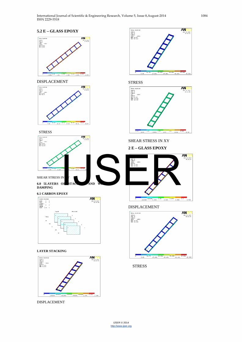
5.2 E – GLASS EPOXY
DISPLACEMENT
STRESS
SHEAR STRESS IN XY
6.0 5LAYERS OF STACKING AND WITHOUT DAMPING
6.1 CARBON EPOXY
LAYER STACKING
DISPLACEMENT
STRESS
SHEAR STRESS IN XY
2 E – GLASS EPOXY
DISPLACEMENT
STRESS
IJSER
International Journal of Scientific & Engineering Research, Volume 5, Issue 8,August-2014 1085 ISSN 2229-5518
IJSER © 2014 http://www.ijser.org
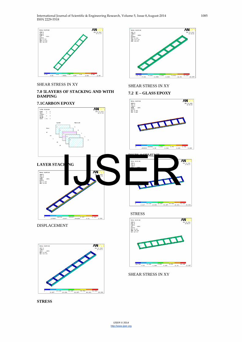
SHEAR STRESS IN XY
7.0 5LAYERS OF STACKING AND WITH DAMPING
7.1CARBON EPOXY
LAYER STACKING
DISPLACEMENT
STRESS
SHEAR STRESS IN XY
7.2 E – GLASS EPOXY
DISPLACEMENT
STRESS
SHEAR STRESS IN XY
IJSER

International Journal of Scientific & Engineering Research, Volume 5, Issue 8,August-2014 1086 ISSN 2229-5518
IJSER © 2014 http://www.ijser.org
8 0 11LAYERS OF STACKING AND WITHOUT DAMPING
8.1 CARBON EPOXY
LAYERSTACKING
LAYERS
DISPLACEMENT
STRESS
SHEAR STRESS IN XY
8.2 E - GLASS EPOXY
DISPLACEMENT
STRESS
SHEAR STRESS IN XY
9.0 11LAYERS OF STACKING AND WITH DAMPING
9.1CARBON EPOXY
IJSER

International Journal of Scientific & Engineering Research, Volume 5, Issue 8,August-2014 1087 ISSN 2229-5518
IJSER © 2014 http://www.ijser.org
LAYER STACKING
DISPLACEMENT
STRESS
SHEAR STRESS IN XY
9.2 E – GLASS EPOXY
DISPLACEMENT
STRESS
SHEAR STRESS IN XY
IJSER

International Journal of Scientific & Engineering Research, Volume 5, Issue 8,August-2014 1088 ISSN 2229-5518
IJSER © 2014 http://www.ijser.org
10.0 RESULTS
10.1 STRUCTURAL ANALYSIS
10.2.1 SINGLE LAYER (WITHOUT RUBBER)
STEEL
CARBON EPOXY
E – GLASS EPOXY
DISPLACEMENT (mm) 1.316 2.869 5.44
1
STRESS (N/mm2) 77.072 92.878 77.0
72
SHEAR STRESS IN XY (N/mm2)
23.823 29.519 23.823
10.3 MODAL ANALYSIS
10.3.1 SINGLE LAYER (WITHOUT RUBBER)
STEEL
CARBON
EPOXY
E – GLASS EPOXY
FREQUENCY (Hz)
10.253 10.365 10.487
DEFLECTION (mm)
0.282693
0.754949 0.516973
FREQUENCY (Hz)
11.184 12.907 10.881
DEFLECTION (mm)
0.436909
0.702322 0.864484
10.2.2 LAYERS
3 LAYERS
5 LAYERS
11 LAYERS
CARBON EPOXY
E-GLASS
CARBON EPOXY
E-GLASS
CARBON EPOXY
E-GLASS
DISP (mm)
WITHOUT RUBBER
1.393
3.733
1.385
3.713
1.385 3.712
RUBBER 1.
746
4.679
1.556
4.169
1.145 3.889
STRESS (N/mm2
)
WITHOUT RUBBER
53.168
53.168
52.922
52.922
52.905 52.905
RUBBER 6
6.871
66.87
59.556
59.556
55.458 55.478
SS IN XY (N/mm2
)
WITHOUT RUBBER
9.372
16.423
16.347
16.347
16.342 16.342
RUBBER
20.639
20.639
18.387
18.387
17.132
17.132
IJSER

International Journal of Scientific & Engineering Research, Volume 5, Issue 8,August-2014 1089 ISSN 2229-5518
IJSER © 2014 http://www.ijser.org
10.3.2 LAYERS
3 LAYERS 5 LAYERS
11 LAYE
RS
CARBON
EPOXY
E-GLASS
CARBON EPOXY
E-GLASS
CARBON EPOXY
E-GLASS
WITHOUT RUBBER
FREQ
(Hz)
11.484 10.626
12.161
10.63
10.458
10.63
DEF (mm)
0.77111
0.535469
0.741566
0.535734
0.741483
0.535026
WITH RUBBER
FREQ
(Hz)
10.456 10.255
10.458
10.52
10.193
10.612
DEF (mm)
0.741723
0.594189
0.741475
0.573445
0.757182
0.553569
WITHOU
FREQ
(H
13.84 11.24
14.624
11.297
12.945
11.297
T RUBBER
z)
DEF (mm)
0.660034
0.526808
0.688868
0.441397
0.657333
0.512095
WITH RUBBER
FREQ
(Hz)
12.943 11.142
12.945
11.247
12.616
11.246
DEF (mm)
0.690787
0.503659
0.685244
0.525117
0.71186
0.525088
11.0 CONCLUSION
Chassis used in a heavy vehicle modeled using Pro/Engineer. Structural and modal analysis is done on the chassis using ANSYS. The analysis is done using three materials STEEL, CARBON EPOXY and E-GLASS EPOXY. And using different layers 3, 5 and 11 without and with damping material as RUBBER.
Presently steel is used for chassis composites Carbon Epoxy and E – Glass Epoxy are considered. By observing structural analysis results, the stress values for Carbon Epoxy and E –Glass Epoxy are less than their respective allowable stress values. So using composites for chassis is safe. By using composites instead of steel, the weight of the chassis reduces 4 times than by using steel because density of steel is more than the composites.
By using layers for same thickness of the chassis, the displacement and stress values are reduced than using as single layer. So it is better to take layers than as single layer.
By observing modal analysis results, vibrations produced are less by using damping
IJSER

International Journal of Scientific & Engineering Research, Volume 5, Issue 8,August-2014 1090 ISSN 2229-5518
IJSER © 2014 http://www.ijser.org
material rubber than vibrations produced without using damping material. So using damping material reduces the vibrations in the chassis.
When comparing the composite materials Carbon Epoxy and E – Glass epoxy, the vibration’s are less using E – Glass Epoxy than by using Carbon Epoxy. Based on a analysis result it is concluded using E-Glass E-poxy , composite is better for chassis.
REFERENCES
Autar K. Kaw, "Mechanics of Composite Materials", CRC press, 1997.
Ahid D. Nashif, David I. G. Jones and John P. Henderson, “Vibration Damping”, John Wiley & Sons Publication, 1985, Newyork.
C. T. Sun and Y. P. Lu, "Vibration Damping of Structural Elements", Prentince Hall PTR, New Jeresy, 1995.
J. M. Biggerstaff and J. B. Kosmatka, “Damping Performance of Cocured Composite Laminates with Embedded Viscoelastic Layers”, Journal of Composite Materials, Vol. 32, No.21/ 1998.
T. E. Alberts and Houchun Xia, “Design and Analysis of Fiber Enhanced Viscoelastic Damping Polymers”, Journal of Vibration and Acoustics, Vol. 117, October 1995, pp. 398-404.
K. J. Buhariwala and J. S. Hansen, "Dynamics of Viscoelastic Structures", AIAA Journal, Vol. 26, February 1988, pp 220-227.
H.J. Beermann, English translation by Guy Tidbury, The Analysis of Commercial Vehicle Structures, Verlag TUV Rheinland GmbH Koln – 1989.
Thomas D Gilespie, Fundamentals of Vehicle Dynamics, SAE 1999.
J Reimpell & H Stoll, The Automotive Chassis: Engineering Principles, SAE-2000.
J Reimpell & H Stoll, The Automotive Chassis: Engineering Principles, ARNOLD – 1996.
Author Profile :
Mr. Bairy Ravinder M.E (CAD/CAM) in Mechanical. Presently working as Assistant Professor in Department of Mechanical Engineering,Guru Nanak Institute of Technology, Ibhrahimpatnam, Hyderabad, 504510,Telangana,India
MS. N.Prashanthi P G Student, Department of Mechanical Engineering, M.Tech, machine desigen VIJAY RURAL ENGINEERING COLLEHE ,Rochis vally,Manikbhandar,Nizamabad,Telangana, India
IJSER