vibration suppression of rotating disc using …umpir.ump.edu.my/8472/1/cd8174.pdf · vibration...
TRANSCRIPT

VIBRATION SUPPRESSION OF ROTATING DISC USING EDDYCURRENT METHOD
MOHD IZUAN BIN HASHIM
Report submitted in partial fulfillment of the requirementsfor the award of Bachelor of Mechanical Engineering with Automotive Engineering
Faculty of Mechanical EngineeringUNIVERSITI MALAYSIA PAHANG
JUNE 2013

vii
ABSTRACT
This paper presents about the vibration behaviour on rotating aluminum disc using
eddy current method. By increasing the induce current with different initial speed
and different air-gap it make a different vibration behavior. The changing magnetic
flux induces eddy currents in the conductor. These currents dissipate energy in the
conductor and generate drag force. One such method is eddy current damping.
Magnetic damping scheme functions through the eddy currents that are generated in
a nonmagnetic conductive material when it is subjected to a time changing magnetic
field. The result of this study show that the increasing of induce current, initial speed
and air-gap give a significant effect to vibration behaviour effected from magnetic
flux density and damping force.

viii
ABSTRAK
Kertas kerja ini membentangkan mengenai kelakuan getaran pada cakera aluminium
yang berputar menggunakan kaedah arus pusar. Dengan meningkatkan arus
pendorong dengan kelajuan awal yang berbeza dan berbeza-jurang udara
menghasilkan getaran tingkah laku yang berbeza. Fluks magnet yang berubah-ubah
mendorong arus pusar dalam konduktor. Arus ini melesapkan tenaga dalam
konduktor dan menjana daya seretan. Satu kaedah itu adalah arus pusar redaman.
Skim redaman magnetic berfungsi melalui arus pusar yang dihasilkan dalam bahan
konduktif nonmagnetic apabila ia tertakluk kepada masa berubah medan magnet.
Hasil kajian ini menunjukkan bahawa semakin meningkat arus pendorong, kelajuan
awal semasa dan jurang udara memberi kesan yang besar kepada tingkah laku
getaran kesan daripada ketumpatan fluks magnet dan daya redaman.
ix
TABLE OF CONTENT
Page
EXAMINERS APPROVAL DOCUMENT ii
SUPERVISOR’S DECLARATION iii
STUDENT’S DECLARATION iv
DEDICATION v
ACKNOWLEDGEMENT vi
ABSTACT vii
ABSTRAK viii
TABLE OF CONTENTS ix
LIST OF TABLES xii
LIST OF FIGURES xiii
LIST OF SYMBOLS xiv
LIST OF ABBREVIATIONS xv
CHAPTER 1 INTRODUCTION
1.1 Introduction 1
1.2 Problems Statement 4
1.3 Objective 4
1.4 Scope Of Project 4
CHAPTER 2 LITERATURE REVIEWS
2.1 Introduction 52.2 Damping 52.3 Eddy Current 52.4 Uses of Eddy Current 72.5 Eddy Current Method 72.6 Factor Affect of Eddy Current 9
2.6.1 Material Conductivity 92.6.2 Permeability 9
x
2.7 Rotating Disc 10
CHAPTER 3 METHODOLOGY
3.1 Introduction 113.2 Flow chart 113.3 Apparatus 13
3.3.1 Motor3.3.2 Accelerometer
1314
3.3.3 Tachometer 143.3.4 DC Power Supply 143.3.5 Electromagnetic and Disc 15
3.4 Experiment Setup 15
CHAPTER 4 RESULT AND DISCUSSION
4.1 Introduction 184.2 Result in time domain 184.3 Result in frequency domain 21
4.3.1 Result for air-gap 2mm and initial speed 500rpm, 300rpmand 100rpm
21
4.3.2 Result for air-gap 4mm and initial speed 100rpm, 300rpmand 500 rpm
24
CHAPTER 5 CONCLUSION AND RECOMMENDATION
5.1 Conclusion 275.2 Recommendation 28

xi
REFERENCES 29
APPENDICES 30

xii
LIST OF TABLES
Table No Title Page
3.1 Design parameters for the experiment setup 17

xiii
LIST OF FIGURES
Figure No Title Page
2.1 Schematic of conductive material passing through a magnetic
field
6
2.2 A Sketch of the eddy currents in a rotating disc 8
3.1 Project flow chart 12
3.2 Electric motor 13
3.3 Accelerometer 13
3.4 Tachometer 14
3.5 DC power supply 14
3.6 Electromagnet and disc 15
3.7 Full view for experiment setup 16
3.8 Dasylab block module 16
4.1 Acceleration vs time for speed 100 rpm, air-gap 2 mm 18
4.2 Acceleration vs time for speed 300 rpm, air-gap 2 mm 19
4.3 Acceleration vs time for speed 500 rpm, air-gap 2 mm 19
4.4 Acceleration vs time for speed 100 rpm, air-gap 4 mm 20
4.5 Acceleration vs time for speed 300 rpm, air-gap 4 mm 20
4.6 Acceleration vs time for speed 500 rpm, air-gap 4mm 21
4.7 Acceleration vs frequency for speed 100 rpm, air-gap 2mm 22
4.8 Acceleration vs frequency for speed 300 rpm, air-gap 2mm 22
4.9 Acceleration vs frequency for speed 500 rpm, air-gap 2mm 23
4.10 Rpm vs current for different initial speed of air-gap 2mm 23
4.11 Acceleration vs frequency for speed 100rpm, air-gap 4mm 24
4.12 Acceleration vs frequency for speed 300rpm, air-gap 4mm 25
4.13 Acceleration vs frequency for speed 500rpm, air-gap 4mm 25
4.14 Rpm vs current for different initial speed of air-gap 4mm 26
xiv
LIST OF SYMBOLS
r Radius
n Number of electromagnet
d Diameter
A Ampere (unit for current)
mm Millimeter

xv
LIST OF ABBREVIATIONS
DC Direct current
RPM Radius per minit
FFT Fast fourier transform
Emf Electromotive force

CHAPTER 1
INTRODUCTION
1.1 INTRODUCTION
Excessive disk vibration degrades the signal from the read/write head in a hard
disk drive, and may destroy the disk drive by a head crash. In the wood-cutting
industry, the undesirable vibration of the circular saw blade results in unacceptable
waste of raw material. For instance, in turbine operation, the unstable vibration of the
turbine wheel can cause turbine failure due to wheel-to-case impact. The excessive
vibrations are not good to many mechanical appliances. It gave bad impact to the
mechanical properties in time and it also affect other thing and not just on the metal
but giving discomfortness on us [1]. Nevertheless there are exist solution to the
problem that we may faces about the excess vibration that we called the vibration
suppression. However, very few can function without ever coming into contact with
the structure. One such method is eddy current damping. This magnetic damping
scheme functions through the eddy currents that are generated in a nonmagnetic
conductive material when it is subjected to a time changing magnetic field. The
magnitude of the magnet field on the conductor can be varying through movement of
the conductor in a stationary magnetic field, by movement of a constant intensity
magnetic source or changing the magnitude of the magnetic source with respect to a
fixed conductor. Once the eddy currents are generated, they circulate in such a way
that they induce their own magnetic field with opposite polarity of the applied field
causing a resistive force. However, due to the electrical resistance of the conducting
material, the induced currents will dissipated into heat at the rate and the

2
force will disappear [2]. In the case of a dynamic system the conductive metal is
continuously moving in the magnetic field and experiences a continuous change in
flux that induces an electromotive force (emf), allowing the induced currents to
regenerate. The process of the eddy currents being generated causes a repulsive
force to be produced that is proportional to the velocity of the conductive metal.
Since the currents are dissipated, energy is being removing from the system, thus
allowing the magnet and conductor to function like a viscous damper. One of the
most useful properties of an eddy current damper is that it forms a means of
removing energy from the system without ever contacting the structure. This means
that unlike other methods of damping such as constrained layer damping, the
dynamic response and material properties are unaffected by its addition into the
system. Furthermore, many applications require a damping system that will not
degrade in performance over time. This is not the case for other viscous dampers, for
instance many dampers require a viscous liquid which may leak over time. These
two points are just a few of the many advantages offered by eddy current damping
systems [3].
However, effective methods of utilizing the eddy current effect to suppress the
transverse vibrations experienced by many structures have not yet been developed.
Therefore, this dissertation will develop several eddy current damping systems that
can be efficiently used to suppress structural vibrations.
In general, large amplitude of transverse vibration is undesirable as it can
degrade the performance of the devices, and in some cases destroy the machines.
These vibration problems are aggravated as industry applications tend to push the
rotation speed of the circular disk even higher. Suppressing the unwanted vibration in
a spinning disk has become an increasing challenge for mechanical engineers and
researchers. One of the most intuitive approaches in preventing excessive vibration
in a spinning disk is to apply space restraints or vibration absorbers on the disk
surface. This approach has been widely adopted in circular saw industry and the
effect of the space restraints on the disk vibration has been studied extensively. In
these analyses, it was found that damping in the space restraints can suppress the disk
vibration when the rotation speed is lower than the critical speed of the disk [3].

3
However, these passive control approaches fail completely in the super-critical speed
range. In implementing active control to suppress the spinning disk vibration, some
developed a proportional-derivative controller aimed at increasing the transverse
stiffness and damping of a circular saw with an electromagnetic actuator. One eddy
current sensor close to the actuator is used to measure the displacement. They
reported that unstable vibration occurs at high control gain because of complex
actuator dynamics which is difficult to accommodate in the controller design. They
used the on-line FFT analysis of the disk displacement to identify the dominant mode
of the disk vibration. The wave amplitude controller modulates control forces on four
electromagnetic actuators to oppose the displacements and velocities predicted by a
minicomputer. While this system indeed suppressed the vibration of the controlled
mode, it excited the uncontrolled mode at higher gain due to observation and control
spillovers. In order to eliminate the observation and control spillovers, some
employed the method of independent modal space. A magnetic drag force is
produced to slow down the motion when a conducting material is moving through a
stationary magnet or a magnet is moving through a stationary conducting material
[4]. The changing magnetic flux induces eddy currents in the conductor. These
currents dissipate energy in the conductor and generate drag force. This phenomenon
is also called eddy current braking. The advantage of the eddy current braking is that
they are non-contacting components which can eliminate the shortcomings of
conventional braking systems such as heating, wearing, vibrations, and
contaminations due to contact friction. Therefore, this method has been proposed to
enhance notational stability of the dual-spin satellite system and to suppress
vibrations in space crafts. Eddy current braking concept is also applied in
dynamometers. The benefits of magnetic drag force are employed to develop various
damping elements for operating without needs of electronic devices and external
power supplies. Analysis of magnetic field and calculation of magnetic drag force are
essential for the design of braking devices by using permanent magnet. However, the
entire process is complex and difficult; it needs to solve Maxwell’s equations in a
time-dependent situation. Besides, many variables involve in this issue and have to
be taken into account [5]. The major parameters including geometry of permanent
magnet, materials of magnet, air gap, conducting materials and distribution of
magnetic flux density.

4
1.2 PROBLEM STATEMENT
Eddy current generated when a non-magnetic conductive metal is placed in a
magnetic field. The use of Eddy Current had been explored as a damper and controls
the vibration of the dynamic systems. Eddy current will act like a viscous damper
and control the vibration of the structure. The problem is to see how the vibration
behavior when the electromagnetic take place on aluminium.
1.3 OBJECTIVES
The objectives of this project is:
i. to reduce vibration at rotating disc using Eddy Current Method
ii. to analyzed vibration on aluminum rotating disc using Eddy Current Method
1.4 SCOPES OF PROJECT
This project is about vibration suppression of rotating disc using Eddy Current
Method. In order to achieve the study objective stated above, the scopes of study
have been defined. DASYLAB software used for the measurement purposes in this
project. Before started the experiment are important to understanding the eddy
current method and study on vibration suppression on rotating disc. Lastly, must to
know how to setup test rig for the experimental.

CHAPTER 2
LITERATURE REVIEW
2.1 INTRODUCTION
This chapter explain about the damping, theory of eddy current, eddy current
on rotating disc, eddy current braking system which taken from the journals,
reference books, and other related resources. This study aims to reduce and analyzed
vibration on aluminum rotating disc. This study also to see the vibration behaviour in
different initial angular speed (rpm), by increasing the induce current from 0A to 3A
and in the different air-gap.
2.2 Damping
Vibrating systems can encounter damping in various ways like intermolecular
friction, sliding friction and fluid resistance [3]. Damping estimation of any systems
is the most difficult in any vibration analysis. Generally damping are complex and
for mechanical systems it is small to compute but even it is small for us to compute
damping is very important for an accurate prediction of vibration response of the
system [3]. Damping is assumed to have neither mass nor elasticity. It is only exists
only if there is relative velocity between two ends of the damper.
2.3 Eddy Current
When a conductive body moving in a magnetic field experiences eddy current.
Similar to eddy current effects due to time-varying fluxes, the skin depth is defined
as the thickness of the skin in which majority of the induced currents appear. As they

6
are excited by an exterior field, they mainly occur at the sides of the body that are
submitted to the magnetic field. High magnetic flux densities occurs at elevated
speed when the eddy currents are pushed towards the surface of the conductor [5].
High flux densities are, however, prevented if soft magnetic material is applied. A
part of the flux is pushed towards the interior of the moving body or appears as
leakage flux around the body. Hence, the behavior of a moving body is largely
dependent on the saturation of the soft magnetic material [6]. Moreover, the flow
path of induced currents is restricted to the actual geometry of the device.
Eddy Currents are closed loops of induced current circulating in planes
perpendicular to the magnetic flux [5]. They normally travel parallel to the coil's
winding and the flow is limited to the area of the inducing magnetic field. Eddy
Currents concentrate near to the surface adjacent to an excitation coil and their
strength decreases with distance from the coil i.e. Eddy Current density decreases
exponentially with depth [7]. This phenomenon is known as the skin effect. Skin
effect arises when the Eddy Currents flowing in the test object at any depth produce
magnetic fields which oppose the primary field, thus reducing the net magnetic flux
and causing a decrease in current flow as the depth increases. Alternatively, Eddy
Currents near the surface can be viewed as shielding the coil's magnetic field,
thereby weakening the magnetic field at greater depths and reducing induced
currents.
Figure 2.1: schematic of conductive material passing through a magnetic field and
the generation of Eddy Current [3]
7
An Eddy Current is induced around the pole area when magnetic flux goes
through a rotating conductive disc [2]. It produced a retarding braking force which
come from the interaction occurred between the Eddy Current and magnetic flux.
The motion has slow down by the magnetic drag force that has been produced while
a conducting material is moving through a stationery magnet, otherwise. The
changing magnetic field will induce Eddy Current in the conductor. These currents
will dissipate energy in the conductor and generate drag force [7].
2.4 Uses of Eddy Current
These induced Eddy Currents generate their own magnetic field. After all, this
is an actual electrical current and any current flowing in a conductor produces a
magnetic field. The detection and measurements of the strength of the magnetic
fields produced by the Eddy Currents makes it possible for us to learn things about
conductive materials without even contacting them. For example, the electrical
conductivity of a material can be determined by the strength of the eddy currents that
form [8]. Since cracks and other breaks in the surface of a material will prevent
Eddy Currents from forming in that region of the surface, Eddy Currents can be used
to detect cracks in materials. This is referred to as Eddy Current testing in the field of
nondestructive testing (NDT). NDT technicians and engineers use Eddy Current
testing to find cracks and other flaws in part of airplanes and other systems where
bad things can happen if the part breaks [9].
2.5 Eddy Current Method
The Eddy Current method is based on the principle of electromagnetic
induction, generating circular electrical currents in a material under test, this is
achieved by the use of a driving alternating magnetic (primary) field [3]. The current
flow induced within the inspected material, will itself produce a magnetic
(secondary) field in opposition to the primary field. The magnetic field strength and
direction are varying in response to the changing current.

8
If the electrical currents find an obstruction (defect damage) they have to
change their flow direction preferring higher conductivity regions which influences
the secondary induced field. This change of the resultant fields produces a change of
electrical impedance measured across a bridge circuit connected to the primary field,
this bridge imbalance can be accurately measured [2]. The amplitude of the induced
current reflects the volume of material loss and the depth of defect. By this principle
the detection of materials integrity can be assessed.
Figure 2.2 : A sketch of the eddy currents in a rotating disc [5].
The crosses represent a steady magnetic field perpendicular to the plane of the
disc. According to Faraday’s law, eddy currents appear in those points of the disc
where the magnetic field increases or decreases [5].
Induced currents appear when electrical conductors undergo conditions of
variable magnetic flux. In particular, we talk about eddy currents when bulk
conductor pieces instead of wires are involved. There are two basic procedures to
achieve such conditions:
• exerting a time-varying magnetic field on a static piece;
• exerting a steady magnetic field on a moving one.

9
An example of the latter class will be investigated. It consists of a rotating
metallic disc, which is subjected to the magnetic field present at the gap of an
electromagnet. Eddy currents appear inside the disc and brake its rotation. This is
the foundation of the electromagnetic braking systems used by heavy vehicles such
as trains, buses or lorries [10].
2.6 FACTORS AFFECT OF EDDY CURRENT
A number of factors, apart from flaws, will affect the Eddy Current response
from a probe. Successful assessment of flaws or any of these factors relies on holding
the others constant, or somehow eliminating their effect on the results. It is this
elimination of undesired response that forms the basis of much of the technology of
eddy current inspection. The main factors are material conductivity, permeability and
rotating disc.
2.6.1 Material conductivity
The conductivity of a material has a very direct effect on the Eddy Current
flow: the greater the conductivity of a material, the greater the flow of eddy currents
on the surface. Conductivity is often measured by an Eddy Current technique, and
inferences can then be drawn about the different factors affecting conductivity, such
as material composition, heat treatment, work hardening etc.
2.6.2 Permeability
This may be described as the ease with which a material can be magnetised.
For non-ferrous metals such as copper, brass, aluminium, and for austenitic stainless
steels the permeability is the same as that of ‘free space’, ie the relative permeability
(µ) is one. For ferrous metals however the value of µ may be several hundred, and
this has a very significant influence on the eddy current response, in addition it is not
uncommon for the permeability to vary greatly within a metal part due to localised
stresses, heating effects etc.

10
2.7 Rotating disc
Rotating discs are the key element in many mechanical applications, such as
grinding wheels, circular saws, gas turbine, and computer disc drive [6]. Generally,
highly number of amplitude of a transverse vibration in rotating disc is undesirable as
it can lowered the performance of the devices, and in some cases it can destroy the
machines [2]. For instance, excessive disk vibration lowered the signal from the read
or write head in a hard disc drive, and may destroy the disc drive by a head crash. In
the wood-cutting industry, the undesirable vibration of the circular saw blade results
in unacceptable waste of raw material. In turbine operation, the unstable vibration of
the turbine wheel can cause turbine failure due to wheel-to-case impact. These
vibration problems are aggravated as industry applications tend to push the rotation
speed of the circular disk even higher. Suppressing the unwanted vibration in a
spinning disk has become an increasing challenge for mechanical engineers and
researchers. One of the most intuitive approaches in preventing excessive vibration
in a spinning disk is to apply space-.xed restraints or vibration absorbers on the disk
surface. This approach has been widely adopted in circular saw industry, and the
effect of the space-.xed restraints on the disk vibration has been studied extensively.
In some analyses, it was found that damping in the space-.xed restraints can suppress
the disk vibration when the rotation speed is lower than the critical speed of the disk.
However, these passive control approaches fail completely in the super-critical speed
range [6].
CHAPTER 3
METHODOLOGY
3.1 INTRODUCTION
The methodology had been done right after the motivation and objective of
the project were identified. This methodology functioned as guidance in order to
complete the project given. The complete structure of methodology had been
illustrated and planned as guideline to achieve the objective of the project.
3.2 FLOW CHART
In order to achieve the aim and the objective of the project, a methodology
was constructed to have a proper guidance for a successful experimentation. A
terminology of works and planning of the experiments conduct was shown in a flow
chart to describe the detail of the project process. The flow chart is the best way to
stay agile with the work in order to keep track of the works. Project flow chart shows
in Figure 3.1

12
YES
FYP 1
FYP 2
No
Figure 3.1: Project flow chart
Start
Understanding the title, determining the project scopes,objective and project background
Literature review
Understand how to setupthe experimental
Complete all apparatus to setup the rig
Final Year Project 1 presentation
Setup the rig for the experimental: plan the steps for the experimentthoroughly
Data collection and analysis
Final Year Project 2 presentation
Complete the report
Finish
Result, discussion andreport
13
3.3 APPARATUS
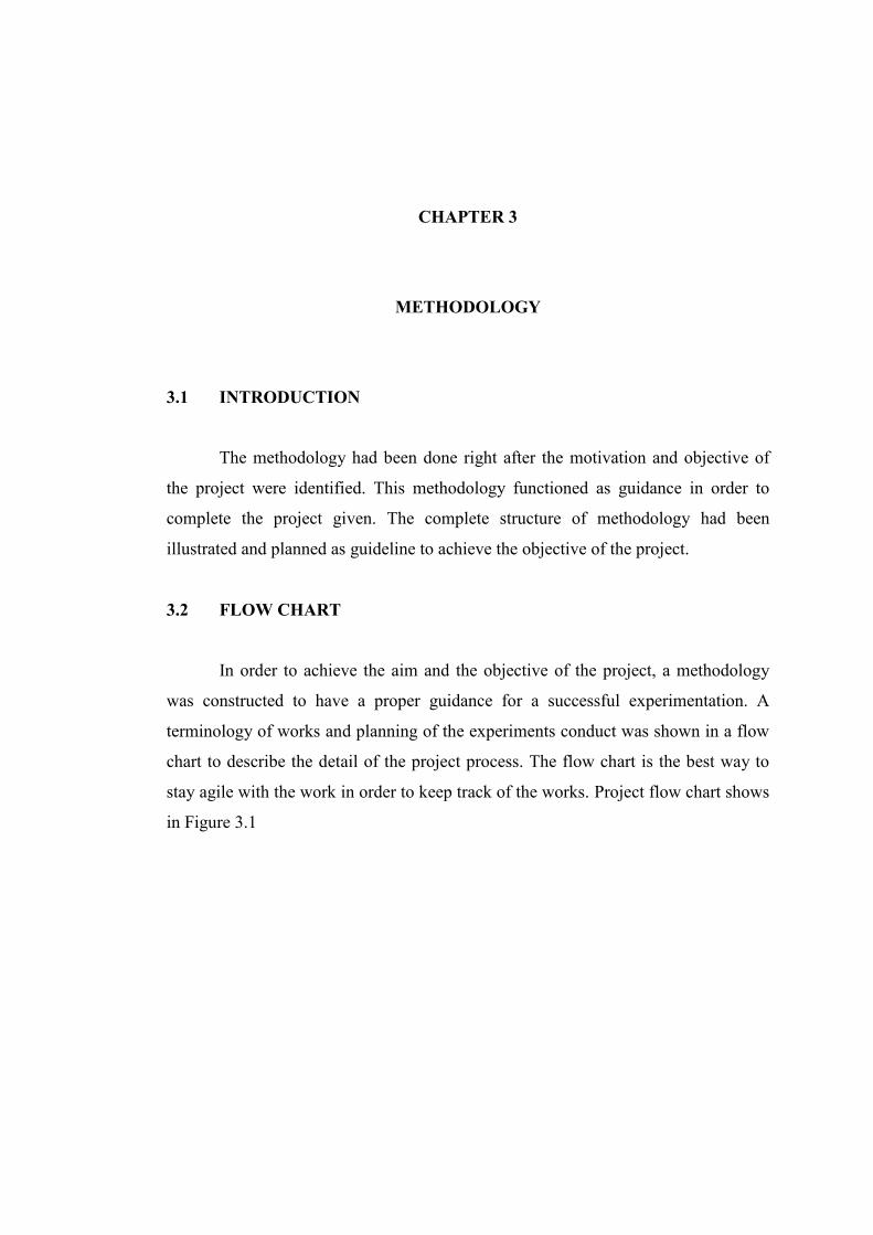
3.3.1 MOTOR
Figure 3.2 : Electric motor
Figure 3.2 shows the picture of electric motor is used in this experiment. The
motor model is Siemens D-91056 DC motor which is capable to rotate as high as
1370 rpm unload. The function of this motor is to rotate the disc with the rpm values
that has been set.
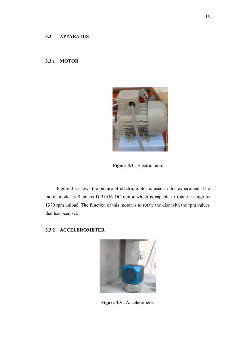
3.3.2 ACCELEROMETER
Figure 3.3 : Accelerometer

14
Figure 3.3 show the picture of accelerometer is used in this experiment to
measure the acceleration and to monitor vibration occurred during the braking. The
accelerometer model has been use is Model 4506B with sensitivity 100 mV/g.
3.3.3 TACHOMETER
Figure 3.4 : Tachometer
Figure 3.4 shows the picture of tachometer is used in this experiment. The
function of tachometer is as an instrument measuring the rotation speed of a shaft or
disk, as in a motor. For this experiment it has been use to measure the rotational of
disc.
3.3.4 DC POWER SUPPLY
Figure 3.5 : DC power supply