vibration testing - data physics · airbus performs six degree of freedom vibration testing for...
TRANSCRIPT

❚ VIBRATION TESTING
76 ❚ AEROSPACE TESTING INTERNATIONAL MARCH 2006
Dataphysics()js.indd 1Dataphysics()js.indd 1 2/3/06 14:30:402/3/06 14:30:40
Aerospace components often operate in a harsh vibration environment. For this reason vibration testing on shaker sys-tems in the laboratory is an essential part of the product evaluation and qualification process. Aerospace vibration qualification requirements range from single shaker tests of avionic systems to large-scale testing of satellites, requiring hundreds of channels.
Real vibration environments are complex and often include multiple excitation sources. Equipment typically experience simultaneous vibration in multiple degrees of freedom. As a result, more accurate simulation of the vibration conditions seen in a product’s real operating environment is best per-formed by multi-degree of freedom vibration testing. It has been shown that, multi degree of freedom testing can often reproduce failures seen in the field that cannot be duplicated with standard single shaker testing.
Multi shaker applicationsITT Aerospace uses multi shaker swept sine testing to qualify satellite electronic components. Testing must be done to simu-late the environment in which the product will operate. This means operating in a thermal vacuum environment. Multiple inertial shakers designed to operate in a thermal vacuum envi-ronment are used to excite the test article. While in a vacuum and under vibration excitation, satellite electronics are opera-tionally tested to certify that they will function in space.
Weapon systems and sub-systems must be qualified for transportation and use on military vehicles. The US Army Redstone Technical Test Center uses measured field vibration data to simulate six degree of freedom vibration experienced by weapons systems in military vehicles. Multi degree of free-
❚ Thomas Reilly & Kevin McIntosh
It is essential that all aerospace parts are put
through vigorous shaker tests. A look at the
multi-degree of freedom vibration testing for all
aerospace applications
Filling the vortex
VIBRATION TESTING ❚
dom testing in the laboratory provides an effective method to qualify new weapon systems eliminating vehicular and driver risk associated with transporting untested live missiles.
Airbus performs six degree of freedom vibration testing for evaluation of Airbus A380 pilot seat design. It is important to know that vibration, especially in severe operating conditions, does not impair the ability of a pilot to operate the aircraft. A special 'man-rated' six degree of freedom shaker system allows a human to safely occupy a seat attached to the shaker system during vibration testing.
Northrop Grumman uses multiple electrodynamic shakers to simulate aero acoustic loading on aircraft electronic compo-nents. Mass models of equipment mounted in aircraft are used to gather vibration data. This data is reduced to a definition of random reference power spectral densities for the attachment points of the shakers. Multiple response measurements are made to validate laboratory simulation and to limit the drive levels if response levels exceed those expected as determined by field measurements.
BRE in Watford, UK uses a multi-shaker control system to simulate noise and vibration in an aircraft cabin based on measurements taken during actual commercial flights. Wave-form replication is used to recreate sound fields in the forward fuselage of an Airbus A300 using 41 inertial shakers and two subwoofers. An array of microphones and accelerometers sup-ply the response feedback signals for control. Volunteer pas-sengers and crew are monitored during real-time simulated flights for health, comfort and stress levels.
Multi-shaker controlMulti-shaker testing is typically performed in one of three shaker configurations: The single xxis multi shaker tests are usually performed on large products, particularly those that
AEROSPACE TESTING INTERNATIONAL MARCH 2006 ❚ 77
Dataphysics()js.indd 2Dataphysics()js.indd 2 8/3/06 11:05:478/3/06 11:05:47
are physically long such as missiles or space vehicles. The shaker systems used within a single axis multi-shaker system used for satellite testing are standard high frequency electro-dynamic shakers. These systems are designed to test very large payloads, without the normal sacrifice of high frequency response that you would typically find with a multi axis shaker system. In some cases, the shakers can be directly coupled to the test fixture, assuming that the vibration control system can achieve accurate phase control between the two shaker sys-tems. If required, hydrostatic spherical couplings can be installed between the shakers and fixture. The hydrostatic spherical couplings will allow for any out of phase rotations during testing and will allow for any foreshortening that will occur as a result of this out of phase condition.
The second configuration is the Multi-Axis Multi-Shaker (table). Components and substructures can be tested on specially designed shaker tables with motion in many degrees of freedom. Seismic qualification tests are performed by mounting a test item to a large multi axis shaker table, typically allowing control of two or three translation axes. The CUBE® from Team Corporation is an example of a six degree of freedom multi-axis multi-shaker table. Within the structure of the CUBE, six inte-grated shakers are arranged in pairs, one pair on each of the X, Y and Z axes. When each pair is operated in phase, pure linear motion parallel to each axis is created. When operated out of phase, a rotational component is produced. Hydrostatic bearings are used in lieu of conventional spherical rod end bearings.
The last configuration includes the Multi-Axis Multi-Shaker (direct). Entire automobiles, aircraft, and other large structures are subjected to the simultaneous excitation of multiple shakers, each directly attached to a point of environmental load input. This provides a realistic simulation of the operational loading under laboratory control. Motion replication, such as road sim-ulation, is often performed in this configuration.
Controlling multiple shakers to simultaneously produce vibration that matches multiple references requires considera-tion of the contribution of each shaker to the response at each control point. The solution involves the measurement of a Mul-tiple Input Multiple Output (MIMO) matrix of transfer functions between the shaker drive signals and the response measured at the control points. This transfer function matrix is inverted and used with the references to generate the multiple drive signals that include compensation for the system dynamic response.
Control signals are not always well defined over the entire frequency bandwidth. This would be the case when a control point is close to a nodal point of a mode of vibration. In such cases it may be necessary to specify more control points than shakers to accurately reproduce the required multi-degree of freedom motion. This results in an over determined transfer function matrix. An over determined matrix is non-square and requires a pseudo inverse technique for matrix inversion. The computational method of the pseudo inverse technique is based on singular value decomposition of the matrix. The singular value decomposition technique also deals well with singularities that may exist in the transfer function matrix.. ❚
Thomas Reilly is the product marketing manager, vibration con-trol systems for Data Physics, while Kevin McIntosh is the shaker operations manager
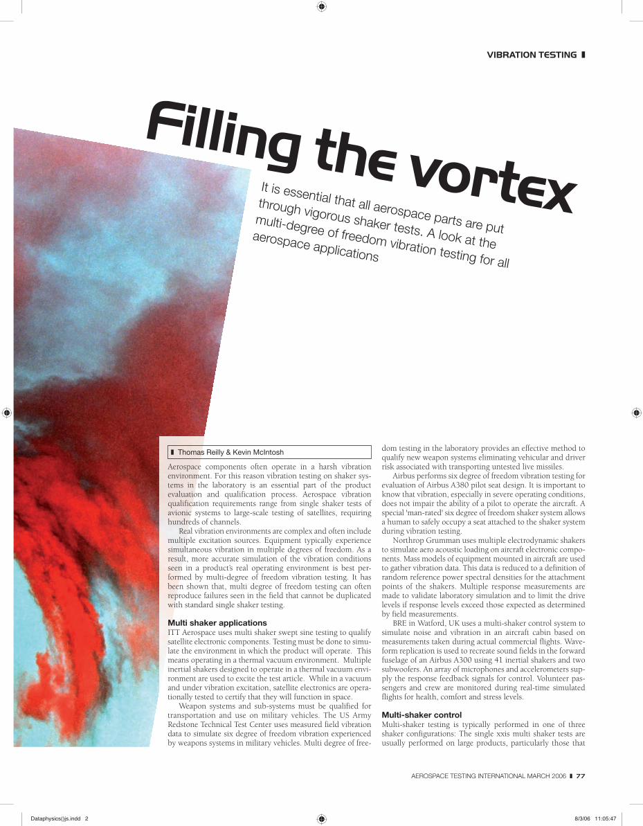
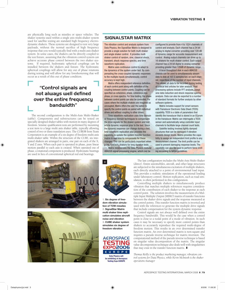
1. Six degree of free-dom vibration simula-tion of TOW missiles 2. SignalStar Matrix multi shaker time repli-cation simulates aircraft noise and vibration 3. CUBE shaker system simulates six degree of freedom vibration
The vibration control and analysis system from Data Physics, the SignalStar Matrix is designed to provide a single solution for both multi shaker and single shaker control. It provides multi shaker control of random, sine, classical shock, transient, shock response spectra, and time waveform replication.
Matrix uses continuous control to adapt to the dynamics of the system under test. By com-pensating the cross-coupled dynamic responses to the multiple inputs simultaneously, control accuracy is kept high.
Matrix offers independent reference definition of each control point along with definition of the coupling between control points. Coupling can be specified as coherence, phase, coherence plus phase, or cross spectra. For Sine testing, the phase between control points can also be controlled. For cases where the multiple shakers are imagined as uncoupled, Matrix offers the user the option to specify the control points as paired with individual drives and without coupling to other drives.
Time waveform replication uses time domain or frequency domain techniques to compensate the drive signals for the shaker system and test article dynamic response prior to the test. Since the dynamic response can change during a test, time waveform replication also provides the capability to update the system transfer function matrix in real time to compensate for these changes. This can be particularly important when using hydraulic shakers for long duration tests.
Matrix incorporates the Data Physics modular ABACUS signal processing engine, which can be
configured to provide from 4 to 1024 channels of control and analysis. Each channel has a 24 bit analog to digital converter providing over 120 dB of dynamic range for accurate measurement and control. Analog output channels can drive up to 16 shakers for multi shaker control. Each output channel has a 24 bit digital to analog converter providing greater than 120dB of dynamic range.
A local throughput disk in each ABACUS chassis can be used to simultaneously stream data to disk at 107.5 samples/sec on each chan-nel, regardless of the number of input channels. This allows all data to be recorded during testing of critical test articles for later analysis. Post processing options include FFT analysis, swept sine data reduction and shock response spectra analysis. Data can also be exported to a number of standard formats for further analysis by other software systems.
Matrix includes support for smart sensors with Transducer Electronic Data Sheet (TEDS) capability. TEDS is a table of parameters that identify the transducer that is stored in an EEprom in the transducer. Matrix can interrogate a TEDS sensor and automatically setup controller input channels to facilitate large channel count tests.
Satellite testing involves lightly damped structures that can be damaged if vibration exceeds design levels. Matrix provides the capa-bility to assign an independent limit profile to any measurement channel. The limit profile can be used to prevent damaging response levels. The capability can also be used to perform force limit-ing according to NASA guidelines.
SIGNALSTAR MATRIX
“Control signals are not always well defined
over the entire frequency bandwidth”
1
2
3
VIBRATION TESTING ❚
Data Physics will be exhibiting at Aerospace
Testing Expo EUROPE
AEROSPACE TESTING INTERNATIONAL MARCH 2006 ❚ 79
Dataphysics()js.indd 3Dataphysics()js.indd 3 8/3/06 11:06:308/3/06 11:06:30