victory a-series actuators · victory a-series actuators 22 glade view rive, roanoke, v 212 8981...
TRANSCRIPT
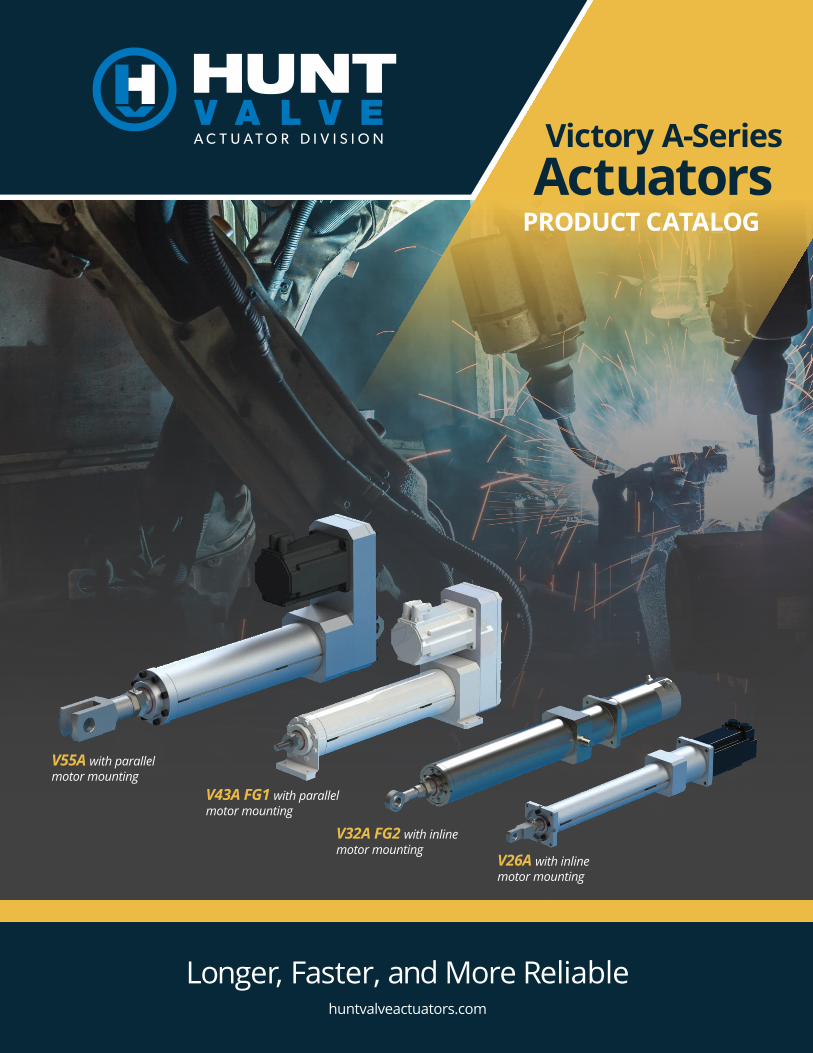
Longer, Faster, and More Reliablehuntvalveactuators.com
V55A with parallel motor mounting
V43A FG1 with parallel motor mounting
V32A FG2 with inline motor mounting
V26A with inline motor mounting
Victory A-SeriesActuators
PRODUCT CATALOG
Victory A-Series Actuators
225 Glade View Drive, Roanoke, VA 24012 USA (540) 857-9871 [email protected] | huntvalveactuators.com
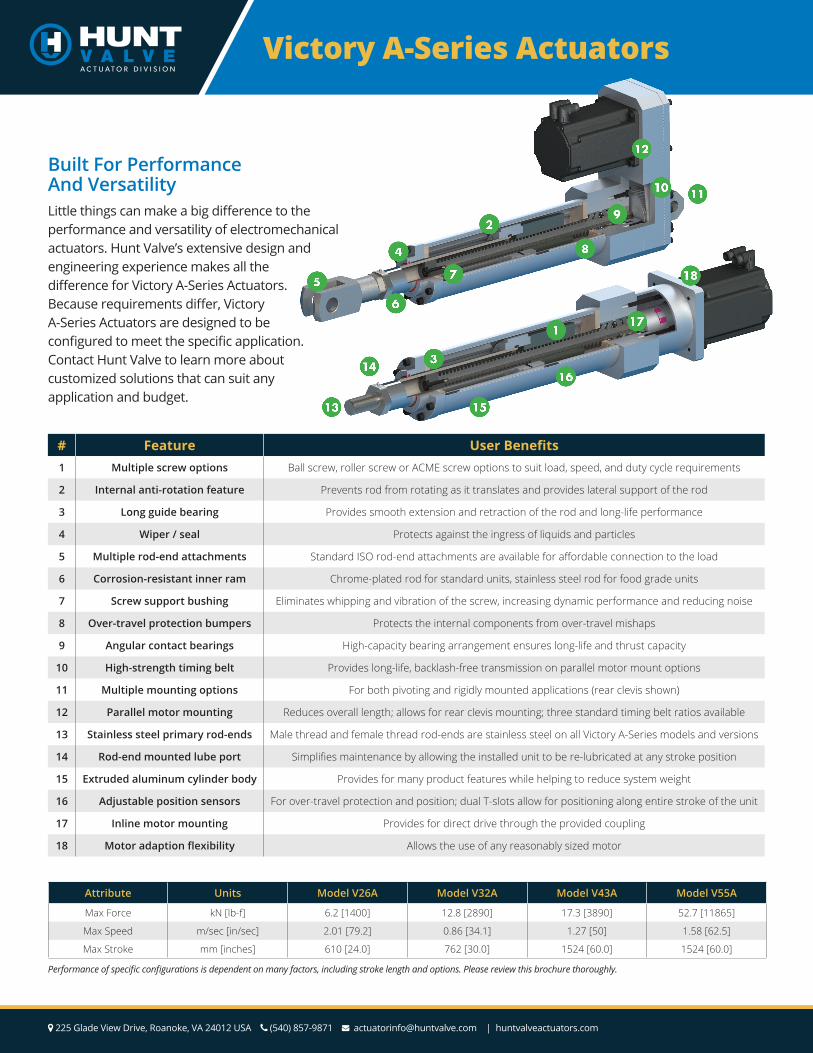
Built For Performance And VersatilityLittle things can make a big difference to the performance and versatility of electromechanical actuators. Hunt Valve’s extensive design and engineering experience makes all the difference for Victory A-Series Actuators. Because requirements differ, Victory A-Series Actuators are designed to be configured to meet the specific application. Contact Hunt Valve to learn more about customized solutions that can suit any application and budget.
# Feature User Benefits1 Multiple screw options Ball screw, roller screw or ACME screw options to suit load, speed, and duty cycle requirements
2 Internal anti-rotation feature Prevents rod from rotating as it translates and provides lateral support of the rod
3 Long guide bearing Provides smooth extension and retraction of the rod and long-life performance
4 Wiper / seal Protects against the ingress of liquids and particles
5 Multiple rod-end attachments Standard ISO rod-end attachments are available for affordable connection to the load
6 Corrosion-resistant inner ram Chrome-plated rod for standard units, stainless steel rod for food grade units
7 Screw support bushing Eliminates whipping and vibration of the screw, increasing dynamic performance and reducing noise
8 Over-travel protection bumpers Protects the internal components from over-travel mishaps
9 Angular contact bearings High-capacity bearing arrangement ensures long-life and thrust capacity
10 High-strength timing belt Provides long-life, backlash-free transmission on parallel motor mount options
11 Multiple mounting options For both pivoting and rigidly mounted applications (rear clevis shown)
12 Parallel motor mounting Reduces overall length; allows for rear clevis mounting; three standard timing belt ratios available
13 Stainless steel primary rod-ends Male thread and female thread rod-ends are stainless steel on all Victory A-Series models and versions
14 Rod-end mounted lube port Simplifies maintenance by allowing the installed unit to be re-lubricated at any stroke position
15 Extruded aluminum cylinder body Provides for many product features while helping to reduce system weight
16 Adjustable position sensors For over-travel protection and position; dual T-slots allow for positioning along entire stroke of the unit
17 Inline motor mounting Provides for direct drive through the provided coupling
18 Motor adaption flexibility Allows the use of any reasonably sized motor
Attribute Units Model V26A Model V32A Model V43A Model V55A
Max Force kN [lb-f] 6.2 [1400] 12.8 [2890] 17.3 [3890] 52.7 [11865]
Max Speed m/sec [in/sec] 2.01 [79.2] 0.86 [34.1] 1.27 [50] 1.58 [62.5]
Max Stroke mm [inches] 610 [24.0] 762 [30.0] 1524 [60.0] 1524 [60.0]
Performance of specific configurations is dependent on many factors, including stroke length and options. Please review this brochure thoroughly.
3
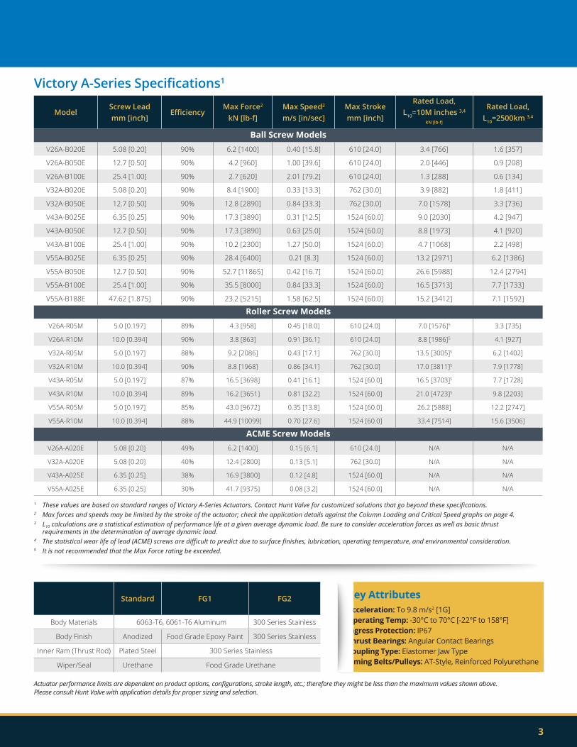
Victory A-Series Specifications1
ModelScrew Lead mm [inch]
EfficiencyMax Force2
kN [lb-f]Max Speed2
m/s [in/sec]Max Stroke mm [inch]
Rated Load,L10=10M inches 3,4
kN [lb-f]
Rated Load,L10=2500km 3,4
Ball Screw ModelsV26A-B020E 5.08 [0.20] 90% 6.2 [1400] 0.40 [15.8] 610 [24.0] 3.4 [766] 1.6 [357]
V26A-B050E 12.7 [0.50] 90% 4.2 [960] 1.00 [39.6] 610 [24.0] 2.0 [446] 0.9 [208]
V26A-B100E 25.4 [1.00] 90% 2.7 [620] 2.01 [79.2] 610 [24.0] 1.3 [288] 0.6 [134]
V32A-B020E 5.08 [0.20] 90% 8.4 [1900] 0.33 [13.3] 762 [30.0] 3.9 [882] 1.8 [411]
V32A-B050E 12.7 [0.50] 90% 12.8 [2890] 0.84 [33.3] 762 [30.0] 7.0 [1578] 3.3 [736]
V43A-B025E 6.35 [0.25] 90% 17.3 [3890] 0.31 [12.5] 1524 [60.0] 9.0 [2030] 4.2 [947]
V43A-B050E 12.7 [0.50] 90% 17.3 [3890] 0.63 [25.0] 1524 [60.0] 8.8 [1973] 4.1 [920]
V43A-B100E 25.4 [1.00] 90% 10.2 [2300] 1.27 [50.0] 1524 [60.0] 4.7 [1068] 2.2 [498]
V55A-B025E 6.35 [0.25] 90% 28.4 [6400] 0.21 [8.3] 1524 [60.0] 13.2 [2971] 6.2 [1386]
V55A-B050E 12.7 [0.50] 90% 52.7 [11865] 0.42 [16.7] 1524 [60.0] 26.6 [5988] 12.4 [2794]
V55A-B100E 25.4 [1.00] 90% 35.5 [8000] 0.84 [33.3] 1524 [60.0] 16.5 [3713] 7.7 [1733]
V55A-B188E 47.62 [1.875] 90% 23.2 [5215] 1.58 [62.5] 1524 [60.0] 15.2 [3412] 7.1 [1592]
Roller Screw ModelsV26A-R05M 5.0 [0.197] 89% 4.3 [958] 0.45 [18.0] 610 [24.0] 7.0 [1576]5 3.3 [735]
V26A-R10M 10.0 [0.394] 90% 3.8 [863] 0.91 [36.1] 610 [24.0] 8.8 [1986]5 4.1 [927]
V32A-R05M 5.0 [0.197] 88% 9.2 [2086] 0.43 [17.1] 762 [30.0] 13.5 [3005]5 6.2 [1402]
V32A-R10M 10.0 [0.394] 90% 8.8 [1968] 0.86 [34.1] 762 [30.0] 17.0 [3811]5 7.9 [1778]
V43A-R05M 5.0 [0.197] 87% 16.5 [3698] 0.41 [16.1] 1524 [60.0] 16.5 [3703]5 7.7 [1728]
V43A-R10M 10.0 [0.394] 89% 16.2 [3651] 0.81 [32.2] 1524 [60.0] 21.0 [4723]5 9.8 [2203]
V55A-R05M 5.0 [0.197] 85% 43.0 [9672] 0.35 [13.8] 1524 [60.0] 26.2 [5888] 12.2 [2747]
V55A-R10M 10.0 [0.394] 88% 44.9 [10099] 0.70 [27.6] 1524 [60.0] 33.4 [7514] 15.6 [3506]
ACME Screw ModelsV26A-A020E 5.08 [0.20] 49% 6.2 [1400] 0.15 [6.1] 610 [24.0] N/A N/A
V32A-A020E 5.08 [0.20] 40% 12.4 [2800] 0.13 [5.1] 762 [30.0] N/A N/A
V43A-A025E 6.35 [0.25] 38% 16.9 [3800] 0.12 [4.8] 1524 [60.0] N/A N/A
V55A-A025E 6.35 [0.25] 30% 41.7 [9375] 0.08 [3.2] 1524 [60.0] N/A N/A
Standard FG1 FG2
Body Materials 6063-T6, 6061-T6 Aluminum 300 Series Stainless
Body Finish Anodized Food Grade Epoxy Paint 300 Series Stainless
Inner Ram (Thrust Rod) Plated Steel 300 Series Stainless
Wiper/Seal Urethane Food Grade Urethane
1 These values are based on standard ranges of Victory A-Series Actuators. Contact Hunt Valve for customized solutions that go beyond these specifications.2 Max forces and speeds may be limited by the stroke of the actuator; check the application details against the Column Loading and Critical Speed graphs on page 4.3 L10 calculations are a statistical estimation of performance life at a given average dynamic load. Be sure to consider acceleration forces as well as basic thrust requirements in the determination of average dynamic load.4 The statistical wear life of lead (ACME) screws are difficult to predict due to surface finishes, lubrication, operating temperature, and environmental consideration.5 It is not recommended that the Max Force rating be exceeded.
Key AttributesAcceleration: To 9.8 m/s2 [1G]Operating Temp: -30°C to 70°C [-22°F to 158°F]Ingress Protection: IP67Thrust Bearings: Angular Contact BearingsCoupling Type: Elastomer Jaw TypeTiming Belts/Pulleys: AT-Style, Reinforced Polyurethane
Actuator performance limits are dependent on product options, configurations, stroke length, etc.; therefore they might be less than the maximum values shown above. Please consult Hunt Valve with application details for proper sizing and selection.
Victory A-Series Actuators
225 Glade View Drive, Roanoke, VA 24012 USA (540) 857-9871 [email protected] | huntvalveactuators.com
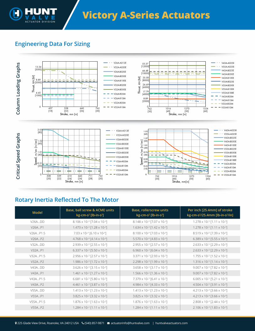
Engineering Data For Sizing
Rotary Inertia Reflected To The Motor
0
4.45[1000]
8.89[2000]
13.34[3000]
457[18]
558[22]
660[26]
762[30]
Thru
st, k
N [l
bf]
Stroke, mm [in]
V26A-A013E
V32A-A020E
V26A-B020E
V26A-B050E
V26A-B100E
V32A-B020E
V32A-B050E
V26A-R05M
V26A-R10M
V32A-R05M
V32A-R10M 0
8.89[2000]
17.79[4000]
26.69[6000]
35.58[8000]
44.48[10000]
53.37[12000]
762[30]
1016[40]
1270[50]
1524[60]
Thru
st, k
N [l
bf]
Stroke, mm [in]
V43A-A025E
V55A-A025E
V43A-B025E
V43A-B050E
V43A-B100E
V55A-B025E
V55A-B050E
V55A-B100E
V55A-B188E
V43A-R05M
V43A-R10M V55A-R05M
V55A-R10M
Colu
mn
Load
ing
Gra
phs
0
0.51[20]
1.01[40]
1.52[60]
2.03[80]
508[20]
559[22]
610[24]
660[26]
711[28]
762[30]
Spee
d, m
/sec
[in/
sec]
Stroke, mm [in]
V26A-A013E
V32A-A020E
V26A-B020E
V26A-B050E
V26A-B100E
V32A-B020E
V32A-B050E
V26A-R05M
V26A-R10M
V32A-R05M
V32A-R10M 0
0.25[10]
0.50[20]
0.76[30]
1.01[40]
1.27[50]
1.52[60]
762[30]
1016[40]
1270[50]
1524[60]
Spee
d, m
/sec
[in/
sec]
Stroke, mm[in]
V43A-A025E
V55A-A025E
V43A-B025E
V43A-B050E
V43A-B100E
V55A-B025E
V55A-B050E
V55A-B100E
V55A-B188E
V43A-R05M
V43A-R10M
V55A-R05M
V55A-R10M
Criti
cal S
peed
Gra
phs
ModelBase, ball screw & ACME units
kg-cm-s2 [lb-in-s2]Base, rollerscrew units
kg-cm-s2 [lb-in-s2]Per inch [25.4mm] of stroke
kg-cm-s2/25.4mm [lb-in-s2/in]
V26A…DD 8.106 x 10⁻⁴ [7.04 x 10⁻⁴] 8.148 x 10⁻⁴ [7.07 x 10⁻⁴] 1.278 x 10⁻⁵ [1.11 x 10⁻⁵]
V26A…P1 1.473 x 10⁻³ [1.28 x 10⁻³] 1.634 x 10⁻³ [1.42 x 10⁻³] 1.278 x 10⁻⁵ [1.11 x 10⁻⁵]
V26A…P1.5 7.03 x 10⁻⁴ [6.10 x 10⁻⁴] 8.100 x 10⁻⁴ [7.03 x 10⁻⁴] 8.519 x 10⁻⁶ [7.39 x 10⁻⁶]
V26A…P2 4.768 x 10⁻⁴ [4.14 x 10⁻⁴] 5.570 x 10⁻⁴ [4.83 x 10⁻⁴] 6.389 x 10⁻⁶ [5.55 x 10⁻⁶]
V32A…DD 2.939 x 10⁻³ [2.55 x 10⁻³] 2.955 x 10⁻³ [2.57 x 10⁻³] 2.633 x 10⁻⁵ [2.29 x 10⁻⁵]
V32A…P1 6.337 x 10⁻³ [5.50 x 10⁻³] 6.960 x 10⁻³ [6.04 x 10⁻³] 2.633 x 10⁻⁵ [2.29 x 10⁻⁵]
V32A…P1.5 2.956 x 10⁻³ [2.57 x 10⁻³] 3.371 x 10⁻³ [2.93 x 10⁻³] 1.755 x 10⁻⁵ [1.52 x 10⁻⁵]
V32A…P2 1.986 x 10⁻³ [1.72 x 10⁻³] 2.298 x 10⁻³ [1.99 x 10⁻³] 1.316 x 10⁻⁵ [1.14 x 10⁻⁵]
V43A…DD 3.626 x 10⁻³ [3.15 x 10⁻³] 3.658 x 10⁻³ [3.17 x 10⁻³] 9.007 x 10⁻⁵ [7.82 x 10⁻⁵]
V43A…P1 1.461 x 10⁻² [1.27 x 10⁻²] 1.566 x 10⁻² [1.36 x 10⁻²] 9.007 x 10⁻⁵ [7.82 x 10⁻⁵]
V43A…P1.5 6.681 x 10⁻³ [5.80 x 10⁻³] 7.379 x 10⁻³ [6.41 x 10⁻³] 6.005 x 10⁻⁵ [5.21 x 10⁻⁵]
V43A…P2 4.461 x 10⁻³ [3.87 x 10⁻³] 4.984 x 10⁻³ [4.33 x 10⁻³] 4.504 x 10⁻⁵ [3.91 x 10⁻⁵]
V55A…DD 1.413 x 10⁻² [1.23 x 10⁻²] 1.413 x 10⁻² [1.23 x 10⁻²] 4.213 x 10⁻⁴ [3.66 x 10⁻⁴]
V55A…P1 3.825 x 10⁻² [3.32 x 10⁻²] 3.825 x 10⁻² [3.32 x 10⁻²] 4.213 x 10⁻⁴ [3.66 x 10⁻⁴]
V55A…P1.5 1.876 x 10⁻² [1.63 x 10⁻²] 1.876 x 10⁻² [1.63 x 10⁻²] 2.808 x 10⁻⁴ [2.44 x 10⁻⁴]
V55A…P2 1.284 x 10⁻² [1.11 x 10⁻²] 1.284 x 10⁻² [1.11 x 10⁻²] 2.106 x 10⁻⁴ [1.83 x 10⁻⁴]
5
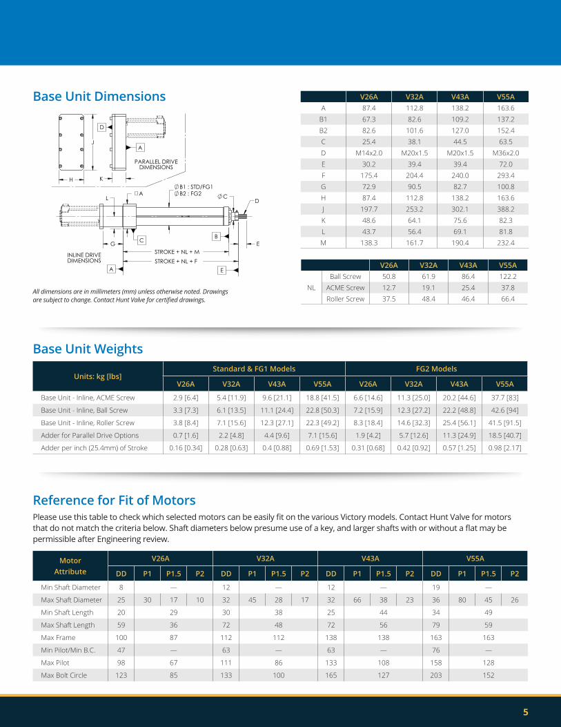
Base Unit Dimensions
Base Unit Weights
Units: kg [lbs]Standard & FG1 Models FG2 Models
V26A V32A V43A V55A V26A V32A V43A V55A
Base Unit - Inline, ACME Screw 2.9 [6.4] 5.4 [11.9] 9.6 [21.1] 18.8 [41.5] 6.6 [14.6] 11.3 [25.0] 20.2 [44.6] 37.7 [83]
Base Unit - Inline, Ball Screw 3.3 [7.3] 6.1 [13.5] 11.1 [24.4] 22.8 [50.3] 7.2 [15.9] 12.3 [27.2] 22.2 [48.8] 42.6 [94]
Base Unit - Inline, Roller Screw 3.8 [8.4] 7.1 [15.6] 12.3 [27.1] 22.3 [49.2] 8.3 [18.4] 14.6 [32.3] 25.4 [56.1] 41.5 [91.5]
Adder for Parallel Drive Options 0.7 [1.6] 2.2 [4.8] 4.4 [9.6] 7.1 [15.6] 1.9 [4.2] 5.7 [12.6] 11.3 [24.9] 18.5 [40.7]
Adder per inch (25.4mm) of Stroke 0.16 [0.34] 0.28 [0.63] 0.4 [0.88] 0.69 [1.53] 0.31 [0.68] 0.42 [0.92] 0.57 [1.25] 0.98 [2.17]
V26A V32A V43A V55AA 87.4 112.8 138.2 163.6
B1 67.3 82.6 109.2 137.2B2 82.6 101.6 127.0 152.4C 25.4 38.1 44.5 63.5D M14x2.0 M20x1.5 M20x1.5 M36x2.0E 30.2 39.4 39.4 72.0F 175.4 204.4 240.0 293.4G 72.9 90.5 82.7 100.8H 87.4 112.8 138.2 163.6J 197.7 253.2 302.1 388.2K 48.6 64.1 75.6 82.3L 43.7 56.4 69.1 81.8M 138.3 161.7 190.4 232.4
V26A V32A V43A V55A
NLBall Screw 50.8 61.9 86.4 122.2
ACME Screw 12.7 19.1 25.4 37.8Roller Screw 37.5 48.4 46.4 66.4
B1 : STD/FG1B2 : FG2
STROKE + NL + F
E
A C
G
L
STROKE + NL + M
D
PARALLEL DRIVEDIMENSIONS
INLINE DRIVE DIMENSIONS
A
BC
E
K
D
A J
H
All dimensions are in millimeters (mm) unless otherwise noted. Drawings are subject to change. Contact Hunt Valve for certified drawings.
Reference for Fit of MotorsPlease use this table to check which selected motors can be easily fit on the various Victory models. Contact Hunt Valve for motors that do not match the criteria below. Shaft diameters below presume use of a key, and larger shafts with or without a flat may be permissible after Engineering review.
Motor Attribute
V26A V32A V43A V55A
DD P1 P1.5 P2 DD P1 P1.5 P2 DD P1 P1.5 P2 DD P1 P1.5 P2
Min Shaft Diameter 8 — 12 — 12 — 19 —
Max Shaft Diameter 25 30 17 10 32 45 28 17 32 66 38 23 36 80 45 26
Min Shaft Length 20 29 30 38 25 44 34 49
Max Shaft Length 59 36 72 48 72 56 79 59
Max Frame 100 87 112 112 138 138 163 163
Min Pilot/Min B.C. 47 — 63 — 63 — 76 —
Max Pilot 98 67 111 86 133 108 158 128
Max Bolt Circle 123 85 133 100 165 127 203 152
Victory A-Series Actuators
225 Glade View Drive, Roanoke, VA 24012 USA (540) 857-9871 [email protected] | huntvalveactuators.com
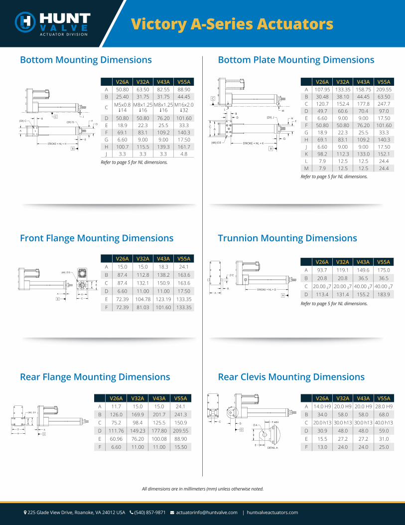
Front Flange Mounting Dimensions
C
B
E
F
(4X) D
A
B
V26A V32A V43A V55AA 15.0 15.0 18.3 24.1B 87.4 112.8 138.2 163.6C 87.4 132.1 150.9 163.6D 6.60 11.00 11.00 17.50E 72.39 104.78 123.19 133.35F 72.39 81.03 101.60 133.35
Rear Flange Mounting Dimensions
A
D
C
B
E
D
(4X) F
V26A V32A V43A V55AA 11.7 15.0 15.0 24.1B 126.0 169.9 201.7 241.3C 75.2 98.4 125.5 150.9D 111.76 149.23 177.80 209.55E 60.96 76.20 100.08 88.90F 6.60 11.00 11.00 15.50
All dimensions are in millimeters (mm) unless otherwise noted.
Bottom Mounting Dimensions
J C B
D
E
(5X) C
STROKE + NL + H
F (2X) G
A
B
V26A V32A V43A V55AA 50.80 63.50 82.55 88.90B 25.40 31.75 31.75 44.45
C M5x0.814
M8x1.2516
M8x1.2516
M16x2.032
D 50.80 50.80 76.20 101.60E 18.9 22.3 25.5 33.3F 69.1 83.1 109.2 140.3G 6.60 9.00 9.00 17.50H 100.7 115.5 139.3 161.7J 3.3 3.3 3.3 4.8
Refer to page 5 for NL dimensions.
Bottom Plate Mounting Dimensions
L M
C
F
B
G
STROKE + NL + K
C A
D
(4X) E
H (2X) J
B
V26A V32A V43A V55AA 107.95 133.35 158.75 209.55B 30.48 38.10 44.45 63.50C 120.7 152.4 177.8 247.7D 49.7 60.6 70.4 97.0E 6.60 9.00 9.00 17.50F 50.80 50.80 76.20 101.60G 18.9 22.3 25.5 33.3H 69.1 83.1 109.2 140.3J 6.60 9.00 9.00 17.50K 98.2 112.3 133.0 152.1L 7.9 12.5 12.5 24.4M 7.9 12.5 12.5 24.4
Refer to page 5 for NL dimensions.
Trunnion Mounting Dimensions
V26A V32A V43A V55AA 93.7 119.1 149.6 175.0B 20.8 20.8 36.5 36.5C 20.00 g7 20.00 g7 40.00 g7 40.00 g7D 113.4 131.4 155.2 183.9
Refer to page 5 for NL dimensions.
STROKE + NL + D
B A
B
C
Rear Clevis Mounting Dimensions
V26A V32A V43A V55AA 14.0 H9 20.0 H9 20.0 H9 28.0 H9B 34.0 58.0 58.0 68.0C 20.0 h13 30.0 h13 30.0 h13 40.0 h13D 30.9 48.0 48.0 59.0E 15.5 27.2 27.2 31.0F 13.0 24.0 24.0 25.0
D
A
D
C
B
E
A F MIN
DETAIL A
7
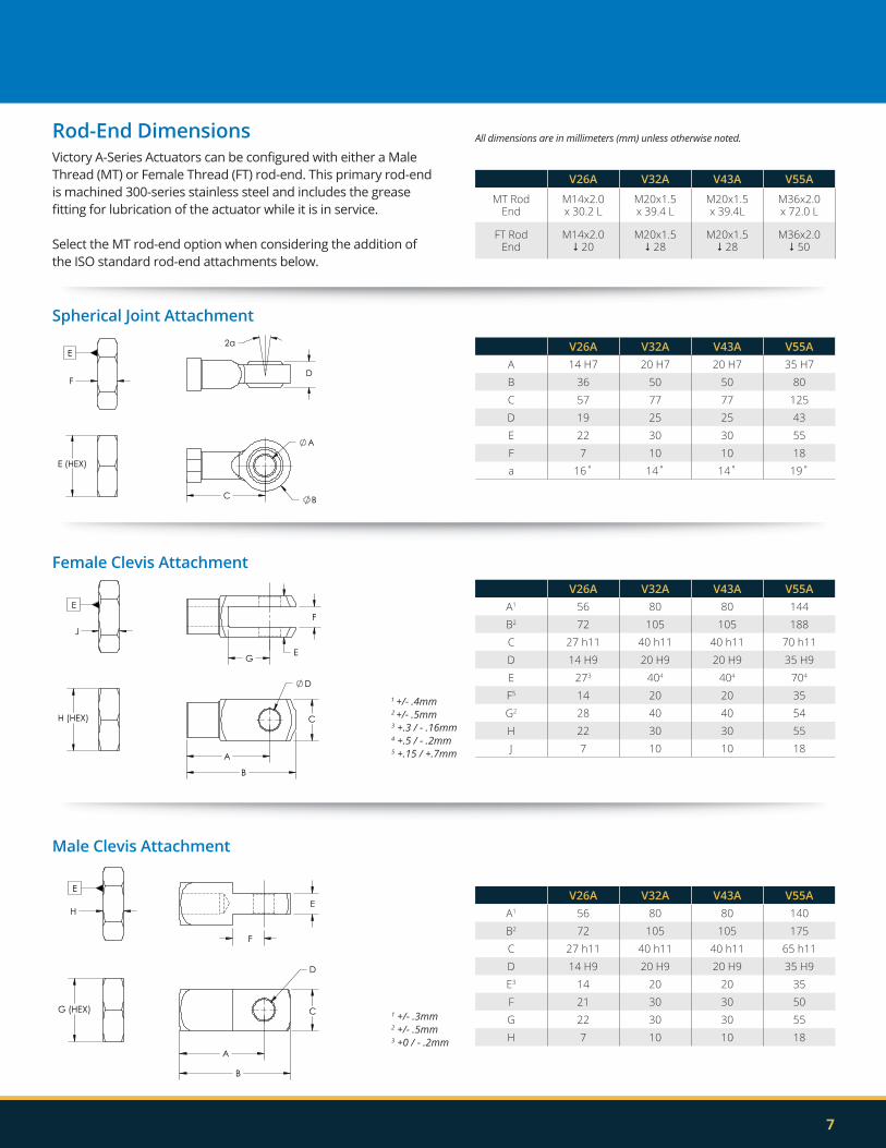
V26A V32A V43A V55A
MT RodEnd
M14x2.0x 30.2 L
M20x1.5x 39.4 L
M20x1.5x 39.4L
M36x2.0x 72.0 L
FT RodEnd
M14x2.0 20
M20x1.5 28
M20x1.5 28
M36x2.0 50
V26A V32A V43A V55AA 14 H7 20 H7 20 H7 35 H7B 36 50 50 80C 57 77 77 125D 19 25 25 43E 22 30 30 55F 7 10 10 18a 16˚ 14˚ 14˚ 19˚
All dimensions are in millimeters (mm) unless otherwise noted.Rod-End DimensionsVictory A-Series Actuators can be configured with either a Male Thread (MT) or Female Thread (FT) rod-end. This primary rod-end is machined 300-series stainless steel and includes the grease fitting for lubrication of the actuator while it is in service.
Select the MT rod-end option when considering the addition of the ISO standard rod-end attachments below.
D
2a
C
A
B
E (HEX)
F
E
Spherical Joint Attachment
D
A
C
B
F
E G
H (HEX)
J
E
Female Clevis Attachment
A
D
C
B
F
E
G (HEX)
H
E
Male Clevis Attachment
V26A V32A V43A V55AA1 56 80 80 140B2 72 105 105 175C 27 h11 40 h11 40 h11 65 h11D 14 H9 20 H9 20 H9 35 H9E3 14 20 20 35F 21 30 30 50G 22 30 30 55H 7 10 10 18
1 +/- .3mm2 +/- .5mm3 +0 / - .2mm
V26A V32A V43A V55AA1 56 80 80 144B2 72 105 105 188C 27 h11 40 h11 40 h11 70 h11D 14 H9 20 H9 20 H9 35 H9E 273 404 404 704
F5 14 20 20 35G2 28 40 40 54H 22 30 30 55J 7 10 10 18
1 +/- .4mm2 +/- .5mm3 +.3 / - .16mm4 +.5 / - .2mm5 +.15 / +.7mm
Victory A-Series Actuators
225 Glade View Drive, Roanoke, VA 24012 USA (540) 857-9871 [email protected] | huntvalveactuators.com 8
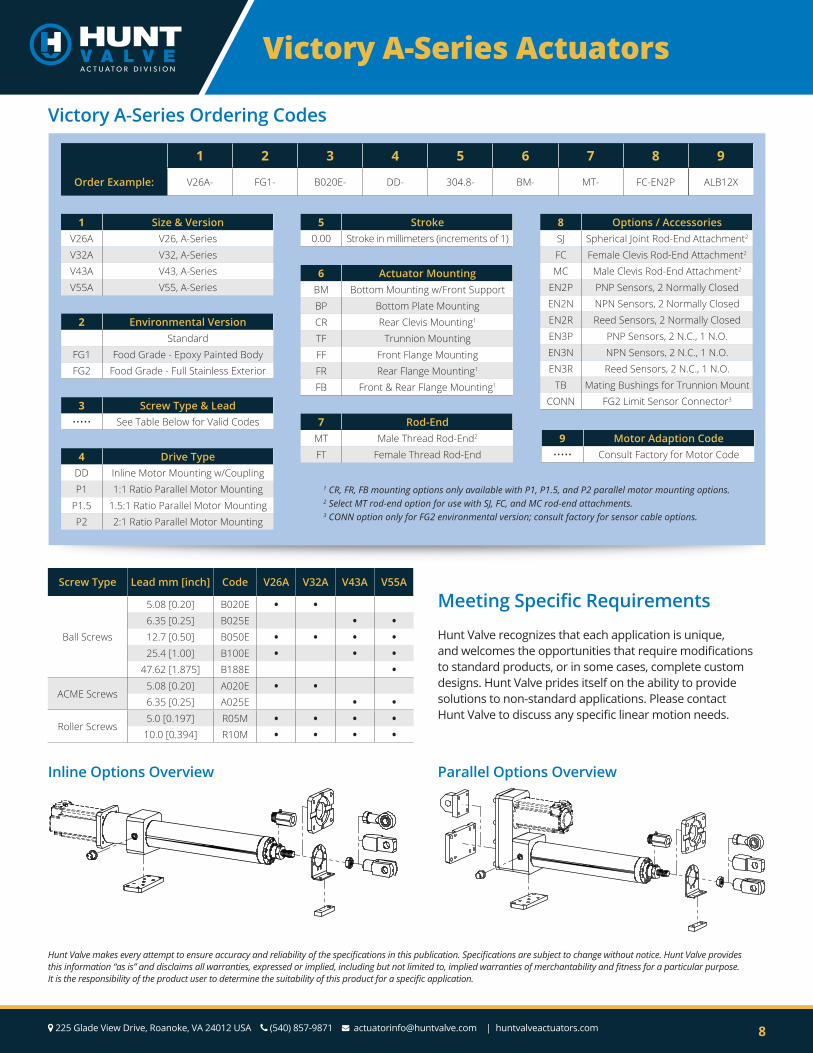
Victory A-Series Ordering Codes
Screw Type Lead mm [inch] Code V26A V32A V43A V55A
Ball Screws
5.08 [0.20] B020E • •6.35 [0.25] B025E • •12.7 [0.50] B050E • • • •25.4 [1.00] B100E • • •
47.62 [1.875] B188E •
ACME Screws5.08 [0.20] A020E • •6.35 [0.25] A025E • •
Roller Screws5.0 [0.197] R05M • • • •
10.0 [0.394] R10M • • • •
1 CR, FR, FB mounting options only available with P1, P1.5, and P2 parallel motor mounting options.2 Select MT rod-end option for use with SJ, FC, and MC rod-end attachments.3 CONN option only for FG2 environmental version; consult factory for sensor cable options.
Hunt Valve makes every attempt to ensure accuracy and reliability of the specifications in this publication. Specifications are subject to change without notice. Hunt Valve provides this information “as is” and disclaims all warranties, expressed or implied, including but not limited to, implied warranties of merchantability and fitness for a particular purpose. It is the responsibility of the product user to determine the suitability of this product for a specific application.
1 2 3 4 5 6 7 8 9
Order Example: V26A- FG1- B020E- DD- 304.8- BM- MT- FC-EN2P ALB12X
1 Size & VersionV26A V26, A-SeriesV32A V32, A-SeriesV43A V43, A-SeriesV55A V55, A-Series
5 Stroke0.00 Stroke in millimeters (increments of 1)
4 Drive TypeDD Inline Motor Mounting w/CouplingP1 1:1 Ratio Parallel Motor Mounting
P1.5 1.5:1 Ratio Parallel Motor MountingP2 2:1 Ratio Parallel Motor Mounting
6 Actuator MountingBM Bottom Mounting w/Front SupportBP Bottom Plate MountingCR Rear Clevis Mounting1
TF Trunnion MountingFF Front Flange MountingFR Rear Flange Mounting1
FB Front & Rear Flange Mounting1
8 Options / AccessoriesSJ Spherical Joint Rod-End Attachment2
FC Female Clevis Rod-End Attachment2
MC Male Clevis Rod-End Attachment2
EN2P PNP Sensors, 2 Normally ClosedEN2N NPN Sensors, 2 Normally ClosedEN2R Reed Sensors, 2 Normally ClosedEN3P PNP Sensors, 2 N.C., 1 N.O.EN3N NPN Sensors, 2 N.C., 1 N.O.EN3R Reed Sensors, 2 N.C., 1 N.O.
TB Mating Bushings for Trunnion MountCONN FG2 Limit Sensor Connector3
7 Rod-EndMT Male Thread Rod-End2
FT Female Thread Rod-End9 Motor Adaption Code
••••• Consult Factory for Motor Code
2 Environmental VersionStandard
FG1 Food Grade - Epoxy Painted BodyFG2 Food Grade - Full Stainless Exterior
3 Screw Type & Lead••••• See Table Below for Valid Codes
Meeting Specific Requirements
Hunt Valve recognizes that each application is unique, and welcomes the opportunities that require modifications to standard products, or in some cases, complete custom designs. Hunt Valve prides itself on the ability to provide solutions to non-standard applications. Please contact Hunt Valve to discuss any specific linear motion needs.
Inline Options Overview Parallel Options Overview