view the report - hse
TRANSCRIPT

Health and Safety Executive
Revised land use planning arrangements around large scale petroleum depots Prepared by Environmental Resources Management Ltd for the Health and Safety Executive 2007
RR511 Research Report

Health and Safety Executive
Revised land use planning arrangements around large scale petroleum depots Dr Andrew Franks CEng MIChemE Environmental Resources Management Ltd Manchester Office Suite 8.01 8 Exchange Quay Manchester M5 3EJ
Following the incident at the Buncefield Oil Storage Depot in December 2005, the Health and Safety Executive (HSE) commissioned Environmental Resources Management (ERM) to assist in reviewing HSE’s approach to providing landuse planning (LUP) advice in the vicinity of similar installations.
Proposals for revised arrangements for provision of LUP advice have been developed. Two options are presented. The proposals are based on a review of information on the effect of blast on building occupants, observations of the blast damage at Buncefield, and a review of some of the justification underpinning certain aspects of the current arrangements. Both of the options proposed would result in greater restriction on development of land in the vicinity of those sites affected.
For both options, the proposed system would operate within a defined geographical area around affected sites. The sensitivity of the size of this area to certain factors has been investigated.
This report and the work it describes were funded by the Health and Safety Executive (HSE). Its contents, including any opinions and/or conclusions expressed, are those of the author alone and do not necessarily reflect HSE policy.
HSE Books
© Crown copyright 2007
First published 2007
All rights reserved. No part of this publication may bereproduced, stored in a retrieval system, or transmitted inany form or by any means (electronic, mechanical,photocopying, recording or otherwise) without the priorwritten permission of the copyright owner.
Applications for reproduction should be made in writing to:Licensing Division, Her Majesty’s Stationery Office,St Clements House, 216 Colegate, Norwich NR3 1BQor by email to hmsolicensing@cabinetoffice.x.gsi.gov.uk
Acknowledgements
The assistance of personnel in HSE’s Hazardous Installations Directorate, and in particular Dr David Painter and Mr John Murray, is gratefully acknowledged.
ii

CONTENTS
CONTENTS III
EXECUTIVE SUMMARY V
1 INTRODUCTION 1
2 CURRENT ARRANGEMENTS 2
2.1 LAND USE PLANNING ZONES 22.2 DEVELOPMENT TYPES AND HSE’S ADVICE 4
3 REQUIREMENT FOR REVIEW OF CURRENT ARRANGEMENTS 8
4 OBJECTIVE OF REVISED ARRANGEMENTS 10
5 OPTIONS FOR REVISED LUP ARRANGEMENTS 11
5.1 CHANGES TO LUP ZONES 155.2 CHANGES TO SENSITIVITY LEVEL DEFINITIONS 15
6 DEVELOPMENT OF PROPOSALS FOR REVISED ARRANGEMENTS 16
6.1 REVISION OF LUP ZONE BOUNDARIES 166.2 REVISION OF SENSITIVITY LEVEL DEFINITIONS 176.2.1 Small housing, hotel / hostel and retail / leisure developments 176.2.2 Workplaces 196.2.3 Summary of Recommendations 206.3 OPTIONS 206.4 APPLICATION 20
7 IMPACT OF THE PROPOSED ARRANGEMENTS 21
7.1 SUMMARY OF IMPACTS 447.2 ADVANTAGES AND DISADVANTAGES 44
8 SENSITIVITY 46
iii

8.1 SOURCE TERM 468.1.1 Sensitivity to Source Geometry 478.1.2 Sensitivity to Fuel Composition 508.2 VAPOUR DISPERSION 508.2.1 Release Duration 518.2.2 Topography 518.2.3 Weather 518.2.4 Presence of Ignition Sources 518.2.5 Source Term 518.3 EXPLOSION PROPERTIES 528.3.1 Explosion Size 528.3.2 Explosion Strength 548.4 SUMMARY 56
9 SUMMARY AND CONCLUSIONS 59
10 REFERENCES 61
APPENDIX 1 REVIEW OF RESEARCH ON EXPLOSION EFFECTS 62
APPENDIX 2 BUILDING DAMAGE OBSERVATIONS 69
APPENDIX 3 ESTABLISHING REVISED ZONE BOUNDARIES 75
APPENDIX 4 CASE SOCIETAL CONCERNS - WORKPLACES 78
iv

EXECUTIVE SUMMARY
Following the incident at the Buncefield Oil Storage Depot in December 2005, the Health and Safety Executive (HSE) commissioned Environmental Resources Management (ERM) to assist in reviewing HSE’s approach to providing land-use planning (LUP) advice in the vicinity of similar installations.
At the time of writing the detailed causes of the incident are still under investigation, although a series of reports have been published by the Major Incident Investigation Board (MIIB) (MIIB, 2006a; MIIB, 2006b; MIIB, 2006c; MIIB, 2006d).
The work performed by ERM has comprised the following:
• performing a review of the current LUP arrangements; • consideration of the various options for revised LUP arrangements in the light of the
experiences at Buncefield; • development of the selected options for revised arrangements; • investigation of the impact of the proposed revised arrangements upon the LUP advice
provided by HSE to local authorities; and, • examination of the sensitivity of the proposed options to a range of factors associated
with the features of the major hazard sites of interest.
The Health and Safety Executive (HSE) provides land use planning (LUP) advice to local authorities regarding applications for development in the vicinity of major hazard installations and major hazard pipelines. This report relates only to HSE’s approach to providing LUP advice around major hazard installations.
At present HSE employs a system for determining the advice to be given that comprises the following elements:
• establishing three concentric (but not necessarily circular) zones around the site in question, termed the inner, middle and outer zones;
• assigning development proposals to one of four ‘Sensitivity Levels’; and, • determining the advice to be given by essentially using a matrix that shows which
development Sensitivity Levels are considered by HSE to be inadvisable in which zones.
For major hazard sites handling or storing flammable substances a ‘protection based’ approach is used to determine the zone boundaries. In most cases the protection based approach involves considering the consequences of a selected event. Zone boundaries are set at the range to different levels of harm that would be expected to result from the event:
• the boundary between the inner and middle zones is usually set at the range at which members of a typical population could be subjected to a level of harm corresponding to a significant likelihood of death;
• the boundary between the middle and outer zones is usually set at the range at which a typical, exposed population could experience a dangerous dose;
v
• the outermost edge of the outer zone is usually set at the range at which a sensitive or vulnerable population could experience a dangerous dose.
The requirement for review of the current arrangements arises from the experience of the Buncefield incident. As a result of the MIIB investigations, it is known that:
• a storage tank was filled to overflowing with petrol; • as the petrol overflowed from the tank a substantial vapour cloud was generated; • the vapour cloud spread over parts of the site and to areas beyond the site boundary; • the vapour cloud was ignited, resulting in a vapour cloud explosion (VCE); and, • the VCE caused extensive damage to buildings, particularly those close to the site of the
explosion.
At present it is not clear why the vapour cloud exploded with such force. Although accidents involving VCEs have occurred before and the VCE phenomenon has been the subject of much scientific investigation, an explanation for the strength of the VCE experienced at Buncefield is currently lacking.
At present HSE performs protection based assessments of sites like that at Buncefield (storage facilities for petroleum products). This assessment involves considering the potential for a VCE. However, on the basis of current scientific understanding of the way in which VCEs occur, the potential for a VCE at a site like Buncefield would be limited to those parts of the facility that provided sufficient confinement or congestion to generate a VCE, such as the tanker loading rack, giving rise to relatively small hazard ranges. The protection based assessment would therefore be likely to be based on other hazards, typically large pool fires.
Proposals have been developed for revised arrangements for HSE’s provision of LUP advice. The proposals have been developed by:
• reviewing published HSE research on the effects of explosions (Jeffries et al., 1997; Galbraith 1998);
• considering the levels of damage to buildings observed around the Buncefield site; • considering the principles upon which HSE’s advice is based; and, • revisiting the justifications underlying the Sensitivity Level definitions for proposed
developments in the light of the other activities.
The specific objectives of the proposed revised arrangements are to:
• establish LUP zone boundaries that take into account observations arising from the Buncefield incident; and,
• provide a decision making framework for use with the revised LUP zones that takes into account the particular nature of the VCE hazard.
The proposed arrangements are protection based. The objective of this and other protection based approaches is to:
vi

“achieve a separation between developments and the site which provides a very high degree of protection against the more likely smaller events, whilst also giving very worthwhile (sometimes almost total) protection against unlikely but foreseeable larger-scale events.” (HSE, 1989).
It is not the objective of the proposed arrangements to provide complete protection for future developments from damage, or for their occupants from harm. Neither is it the objective of the proposed arrangements to suggest what should be done about existing land use around affected sites.
It was judged that any revised approach should have regard for the current state of knowledge regarding events at Buncefield, and should be somewhat precautionary in nature.
Two options are presented:
• Option A: On the basis of blast damage observations at Buncefield, increase the size of the LUP zones only; or,
• Option B: Increase the size of the LUP zones and revise the development Sensitivity Levels.
Under the current system the Buncefield site has the inner, middle and outer zone boundaries set at distances of 120 m, 135 m and 185 m respectively. The proposed system would increase these distances to 250 m, 300 m and 400 m respectively.
The proposed changes to the Sensitivity Levels under Option B would place greater restrictions on the types of development that HSE would not advise against in the inner zone.
It is recommended that the proposed arrangements are applied to those sites which are similar to Buncefield in a number of important respects. These similarities would indicate that on the basis of what is known at present, the site has the potential to give rise to a comparable VCE.
If implemented, it is recommended that the proposed arrangements are applied to sites with the following characteristics:
• the site is classed as either ‘upper tier’ or ‘lower tier’ under the Control of major Accident Hazards Regulations 1999 (the COMAH Regulations);
• the site stores petroleum in vertical, cylindrical, non-refrigerated above-ground storage tanks with side walls greater than 5 m in height; and,
• the filling rate of the storage tanks is greater than 100 m3 / hour.
These criteria align with those used by the Buncefield Standards Task Group, a joint COMAH Competent Authority and Industry committee (HSE, 2006).
In comparison with the current system, the proposed changes will, if implemented, result in:
• significantly larger zones for the sites affected (for both Options A and B);
vii

• as a result of the increased area within the zones, a larger number of consultations concerning proposed developments in the vicinity of affected sites (for both Options A and B); and,
• more restrictive advice concerning developments in the inner zone (for Option B).
Furthermore, it is recognised that there may be significant implications in the proposed system for other types of site. These sites include bulk LPG (liquefied petroleum gas) storage, gasholders, other flammable liquid storage and other facilities presenting a hazard with an associated significant likelihood of death in the inner zone (including VCEs and other hazards such as fireballs). A review of the implications of the study findings for LUP arrangements applicable to other types of site is recommended.
An investigation of the sensitivity of the size of the proposed LUP zone boundaries to various factors was undertaken. The factors considered included:
• the rate at which vapour is formed and the conditions under which this occurs (the source term);
• the way in which the cloud moves (the dispersion of the vapour); • the quantity of fuel involved in the explosion (the explosion size); and, • the violence of the explosion (the explosion strength).
The factors considered to have the greatest influence on the size of the zones were:
• the geometry of the storage tanks at the site (this affects the way the liquid contents behave in the event of a tank being overfilled);
• the duration of a release (this affects the size of the flammable vapour cloud formed); • the topography of the tank surroundings (features in the surroundings such as slopes and
obstacles have a marked effect on the behaviour of the vapour cloud); and, • the weather conditions at the time that a release occurs (calm, low wind speed
conditions favour formation of a large cloud).
It is important to note that:
• several of these factors (tank geometry, time to ignition and topography) are strongly site-specific;
• it is conceivable that a combination of differences in these factors could lead to an explosion with more serious consequences than Buncefield;
• in the time available it has not been possible to quantify the impact of all of these factors on land-use planning zone boundaries; and,
• the reasons for the strength of the explosion at Buncefield are not yet understood, further investigation may indicate that there are additional factors that are important.
viii
1 INTRODUCTION
Following the incident at the Buncefield Oil Storage Depot in December 2005, the Health and Safety Executive (HSE) commissioned Environmental Resources Management (ERM) to assist in reviewing HSE’s approach to providing land-use planning (LUP) advice in the vicinity of similar installations.
At the time of writing the detailed causes of the incident are still under investigation, although a series of reports have been published by the Major Incident Investigation Board (MIIB) (MIIB, 2006a; MIIB, 2006b; MIIB, 2006c; MIIB, 2006d).
The work performed by ERM has comprised the following:
• Performing a review of the current LUP arrangements; • Consideration of the various options for revised LUP arrangements in the light of the
experiences at Buncefield; • Development of the selected options for revised arrangements; • Investigation of the impact of the proposed revised arrangements upon the LUP advice
provided by HSE to local authorities; and, • Examination of the sensitivity of the proposed options to a range of factors associated
with the features of the major hazard sites of interest.
1
2 CURRENT ARRANGEMENTS
The Health and Safety Executive (HSE) provides land use planning (LUP) advice to local authorities regarding applications for development in the vicinity of major hazard installations and major hazard pipelines. This report relates only to HSE’s approach to providing LUP advice around major hazard installations.
Major hazard installations are defined as those sites that are required to have Hazardous Substances Consent (DETR, 2000), obtained from the appropriate Hazardous Substances Authority (usually part of the Local Authority). The Hazardous Substances Consent (or Consent for short) defines the quantities of dangerous substances that the site can hold, and may also define the size of the largest storage vessels, the locations of vessels, the locations of areas used to store transportable containers and the maximum temperatures and pressures within storage and process vessels.
Major hazard pipelines (HSE, 1996) are defined in accordance with the kind of material they convey (whether or not it is a ‘dangerous fluid’ under the terms of the legislation). What constitutes a dangerous fluid depends on the pipeline operating conditions as well as the nature of the material conveyed.
The decision-making algorithm used to determine the appropriate advice in a given case is embodied in decision support software called PADHI (Planning Advice for Developments near Hazardous Installations). The PADHI tool is described in a document that may be downloaded from the HSE website (HSE, undated).
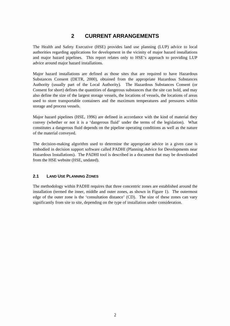
2.1 LAND USE PLANNING ZONES
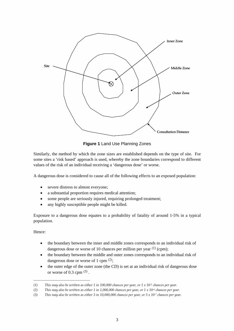
The methodology within PADHI requires that three concentric zones are established around the installation (termed the inner, middle and outer zones, as shown in Figure 1). The outermost edge of the outer zone is the ‘consultation distance’ (CD). The size of these zones can vary significantly from site to site, depending on the type of installation under consideration.
2
Site
Inner Zone
Middle Zone
Outer Zone
Consultation Distance
Site
Inner Zone
Middle Zone
Outer Zone
Consultation Distance
Figure 1 Land Use Planning Zones
Similarly, the method by which the zone sizes are established depends on the type of site. For some sites a ‘risk based’ approach is used, whereby the zone boundaries correspond to different values of the risk of an individual receiving a ‘dangerous dose’ or worse.
A dangerous dose is considered to cause all of the following effects to an exposed population:
• severe distress to almost everyone; • a substantial proportion requires medical attention; • some people are seriously injured, requiring prolonged treatment; • any highly susceptible people might be killed.
Exposure to a dangerous dose equates to a probability of fatality of around 1-5% in a typical population.
Hence:
• the boundary between the inner and middle zones corresponds to an individual risk of dangerous dose or worse of 10 chances per million per year (1) (cpm);
• the boundary between the middle and outer zones corresponds to an individual risk of dangerous dose or worse of 1 cpm (2);
• the outer edge of the outer zone (the CD) is set at an individual risk of dangerous dose or worse of 0.3 cpm (3) .
(1) This may also be written as either 1 in 100,000 chances per year, or 1 x 10⁻⁵ chances per year. (2) This may also be written as either 1 in 1,000,000 chances per year, or 1 x 10⁻⁶ chances per year. (3) This may also be written as either 3 in 10,000,000 chances per year, or 3 x 10⁻⁷ chances per year.
3

In general, a ‘risk based’ approach is used when the site in question stores or processes toxic substances such as chlorine.
For other sites (typically those handling flammable substances) a ‘protection based’ approach is used. In most cases the protection based approach involves considering the consequences of a selected event (whereas a risk based approach considers both the consequences and likelihood of a range of events). Zone boundaries are set at the range to different levels of harm that would be expected to result from the event:
• the boundary between the inner and middle zones is usually set at the range at which members of a typical population could be subjected to a level of harm corresponding to a significant likelihood of death;
• the boundary between the middle and outer zones is usually set at the range at which a typical, exposed population could experience a dangerous dose;
• the outermost edge of the outer zone is usually set at the range at which a sensitive or vulnerable population could experience a dangerous dose.
2.2 DEVELOPMENT TYPES AND HSE’S ADVICE
Proposed developments are assigned to one of four sensitivity levels, as shown in Table 1. More detailed definitions are provided in the PADHI document.
Table 1 Development Sensitivity Levels
Level Description 1 Based on normal working population 2 Based on the general public – at home and involved in normal activities 3 Based on vulnerable members of the public (children, those with mobility
difficulties or those unable to recognise physical danger) 4 Large examples of Level 3 and large outdoor examples of Level 2.
In each case there are some ‘exclusions’. For example, small housing developments of 1-2 dwellings are ‘excluded’ from Level 2 and placed into Level 1.
For a given development proposal, advice is then generated by essentially using the decision matrix shown in Table 2.
Table 2 Decision Matrix
Sensitivity Level Inner Zone Middle Zone Outer Zone 1 DAA DAA DAA 2 AA DAA DAA 3 AA AA DAA 4 AA AA AA AA: Advise against DAA: Don’t advise against
It should be noted that HSE’s role in the planning process is advisory. The decision as to whether a proposed development receives planning permission rests with the local authority,
4

taking into account the advice supplied by HSE. The local authority has to weigh in the balance all of the factors relating to a proposed development (economic, social, environmental, safety) in reaching its decision.
However, HSE has the option to have an application ‘called-in’ for determination by the Secretary of State where it believes that the risks are substantial and the local authority has not given due weight to its advice in coming to their decision.
The following factors would favour calling in the application:
• Any proposals for significant residential development or development for vulnerable populations in the inner zone;
• Proposals where the risk of death exceeds the tolerability limit for a member of the public of 1 x 10⁻⁴ per year (HSE, 2001);
• Proposals where there are substantial numbers of people exposed to the risk, giving rise to a high degree of societal concern;
• Proposals where the endangered population is particularly sensitive, (e.g., the development is a hospital, school or old people’s home);
• Whether there have been previous call-ins in similar circumstances; • Whether there are issues of national concern as opposed to merely of local importance;
or, • Whether there is clear evidence that the case concerned is being used to challenge
HSE’s risk criteria for land-use planning and failure to meet that challenge would damage HSE’s credibility; or where a decision against HSE’s advice could, by precedent, set aside parts of the relevant legislation.
For the purposes of this paper, Sensitivity Level 1 developments are of particular interest, since under the current system they would not be advised against even if they were at a location adjacent to a major hazard site boundary (see Table 2 above). Further details of the definition of Sensitivity Level 1 developments have been extracted from the PADHI document and are displayed in Table 3. Those development types which are assigned to Level 1 as a result of being excluded from other Levels are shown in Table 4.
5
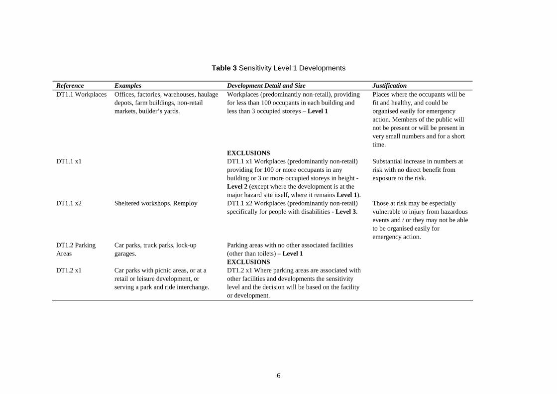
Table 3 Sensitivity Level 1 Developments
Reference Examples Development Detail and Size Justification DT1.1 Workplaces Offices, factories, warehouses, haulage
depots, farm buildings, non-retail markets, builder’s yards.
Workplaces (predominantly non-retail), providing for less than 100 occupants in each building and less than 3 occupied storeys – Level 1
Places where the occupants will be fit and healthy, and could be organised easily for emergency action. Members of the public will not be present or will be present in very small numbers and for a short time.
EXCLUSIONS DT1.1 x1
DT1.1 x2
DT1.2 Parking Areas
Sheltered workshops, Remploy
Car parks, truck parks, lock-up garages.
DT1.1 x1 Workplaces (predominantly non-retail) providing for 100 or more occupants in any building or 3 or more occupied storeys in height - Level 2 (except where the development is at the major hazard site itself, where it remains Level 1). DT1.1 x2 Workplaces (predominantly non-retail) specifically for people with disabilities - Level 3.
Parking areas with no other associated facilities (other than toilets) – Level 1 EXCLUSIONS
Substantial increase in numbers at risk with no direct benefit from exposure to the risk.
Those at risk may be especially vulnerable to injury from hazardous events and / or they may not be able to be organised easily for emergency action.
DT1.2 x1 Car parks with picnic areas, or at a retail or leisure development, or serving a park and ride interchange.
DT1.2 x1 Where parking areas are associated with other facilities and developments the sensitivity level and the decision will be based on the facility or development.
6

Table 4 Sensitivity Level 1 Developments - Exclusions from Other Levels
Reference Examples Development Detail and Size Justification DT2.1 x1 (Exclusion from DT2.1, Infill, backland development. Developments of 1 or 2 dwelling Minimal increase in numbers at risk. Housing) units - Level 1. DT2.2 x1 (Exclusion from DT2.2, Smaller - guest houses, hostels, youth Accommodation of less than 10 beds Minimal increase in numbers at risk. Hotel / Hostel / Holiday hostels, holiday homes, halls of or 3 caravan / tent pitches - Level 1 Accommodation) residence, dormitories, holiday
caravan sites, camping sites. DT2.3 x1 (Exclusion from DT2.3, Estate roads, access roads. Single carriageway roads – Level 1 Minimal numbers present and mostly Transport Links) a small period of time exposed to
risk. Associated with other development.
Any railway or tram track. Railways – Level 1 Transient population, small period of time exposed to risk. Periods of time with no population present.
DT2.4 x1 (Exclusion from DT2.4, Development with less than 250 m2 Minimal increase in numbers at risk. Indoor Use by Public) total floor space – Level 1
7
3 REQUIREMENT FOR REVIEW OF CURRENT ARRANGEMENTS
The requirement for review of the current arrangements arises from the experience of the Buncefield incident. As a result of the MIIB investigations, it is known that:
• a storage tank was filled to overflowing with petrol; • as the petrol overflowed from the tank a substantial vapour cloud was generated; • the vapour cloud spread over parts of the site and to areas beyond the site boundary; • the vapour cloud was ignited, resulting in a vapour cloud explosion (VCE); and, • the VCE caused extensive damage to buildings, particularly those close to the site of the
explosion.
Flammable vapour will burn if it is mixed with sufficient air and ignited. Current thinking is that:
• a fuel-air cloud that burns in the open (i.e. in the absence of any confining structures such as walls or roofs) will burn relatively slowly and generate little if any blast pressure; and,
• in order to generate damaging levels of blast pressure, the fuel-air cloud needs to be at least partially confined (i.e. located within walls and/or a roof) or be located within a congested region (i.e. engulfing obstacles such as pipes, steel frames, vessels etc.).
It is also known that ignition of a fuel-air cloud within a small confined volume can produce an explosion which propagates into that (larger) part of the cloud which is outside the confined volume. This is termed ‘bang box’ ignition.
It is also important to note that the characteristics of the blast produced by a VCE differ somewhat from those of the blast produced by a ‘conventional’ explosive such as TNT.
At present it is not clear why the vapour cloud exploded with such force. Although accidents involving VCEs have occurred before and the VCE phenomenon has been the subject of much scientific investigation, an explanation for the strength of the VCE experienced at Buncefield is currently lacking.
At present HSE performs protection based assessments of sites like that at Buncefield (storage facilities for petroleum products). This assessment involves considering the potential for a VCE. However, on the basis of current scientific understanding of the way in which VCEs occur, the potential for a VCE at a site like Buncefield would be limited to those parts of the facility that provided sufficient confinement or congestion to generate a VCE, such as the tanker loading rack, giving rise to relatively small hazard ranges. The protection based assessment would therefore be likely to be based on other hazards, typically large pool fires.
It seems possible that the incident at Buncefield may alter current scientific understanding of VCE mechanisms. This in turn may cause HSE (and risk assessment practitioners generally) to re-think their approach to the assessment of sites storing large quantities of flammable
8

substances. However, a detailed understanding of events at Buncefield is at least some months (and possibly, if further experimental investigations are required, some years) away.
9
4 OBJECTIVE OF REVISED ARRANGEMENTS
The specific objectives of the proposed revised arrangements are to:
• establish LUP zone boundaries that take into account observations arising from the Buncefield incident; and,
• provide a decision making framework for use with the revised LUP zones that takes into account the particular nature of the VCE hazard.
The proposed arrangements are protection based. The objective of this and other protection based approaches is to:
“achieve a separation between developments and the site which provides a very high degree of protection against the more likely smaller events, whilst also giving very worthwhile (sometimes almost total) protection against unlikely but foreseeable larger-scale events.” (HSE, 1989).
It is not the objective of the proposed arrangements to provide complete protection for future developments from damage, or for their occupants from harm. Neither is it the objective of the proposed arrangements to suggest what should be done about existing land use around affected sites.
10
5 OPTIONS FOR REVISED LUP ARRANGEMENTS
The principal features of the system used by HSE for providing LUP advice are:
• The zones around the site; • The development categories; and, • The decision matrix.
Therefore revised arrangements could involve alterations to one or more of these features.
An initial list of options was developed by HSE and presented to ERM for consideration. These options are listed in Table 5, together with the author’s comments in each case.
11
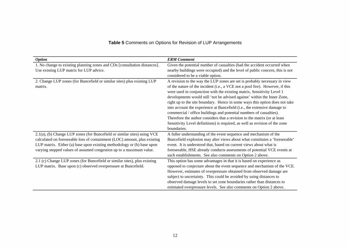
Table 5 Comments on Options for Revision of LUP Arrangements
Option 1. No change to existing planning zones and CDs [consultation distances]. Use existing LUP matrix for LUP advice.
2. Change LUP zones (for Buncefield or similar sites) plus existing LUP matrix.
2.1(a), (b) Change LUP zones (for Buncefield or similar sites) using VCE calculated on foreseeable loss of containment (LOC) amount, plus existing LUP matrix. Either (a) base upon existing methodology or (b) base upon varying stepped values of assumed congestion up to a maximum value.
ERM Comment Given the potential number of casualties (had the accident occurred when nearby buildings were occupied) and the level of public concern, this is not considered to be a viable option. A revision to the way the LUP zones are set is probably necessary in view of the nature of the incident (i.e., a VCE not a pool fire). However, if this were used in conjunction with the existing matrix, Sensitivity Level 1 developments would still ‘not be advised against’ within the Inner Zone, right up to the site boundary. Hence in some ways this option does not take into account the experience at Buncefield (i.e., the extensive damage to commercial / office buildings and potential numbers of casualties). Therefore the author considers that a revision to the matrix (or at least Sensitivity Level definitions) is required, as well as revision of the zone boundaries. A fuller understanding of the event sequence and mechanism of the Buncefield explosion may alter views about what constitutes a ‘foreseeable’ event. It is understood that, based on current views about what is foreseeable, HSE already conducts assessments of potential VCE events at such establishments. See also comments on Option 2 above.
2.1 (c) Change LUP zones (for Buncefield or similar sites), plus existing LUP matrix. Base upon (c) observed overpressure at Buncefield.
This option has some advantages in that it is based on experience as opposed to conjecture about the event sequence and mechanism of the VCE. However, estimates of overpressure obtained from observed damage are subject to uncertainty. This could be avoided by using distances to observed damage levels to set zone boundaries rather than distances to estimated overpressure levels. See also comments on Option 2 above.
12

Option ERM Comment 2.2(a), (b) Change LUP zones (for Buncefield or similar sites) using VCE calculated on extremely large loss of containment (LOC) amount, plus existing LUP matrix. Either (a) base upon existing methodology or (b) base upon varying stepped values of assumed congestion up to a maximum value.
Current understanding of VCE mechanisms indicates that, in the case of a very large release, the magnitude of the explosion becomes limited by the size of the confined / congested volume available rather than by the size of the cloud. At a site similar to Buncefield the available confined / congested volumes are typically small (e.g. loading racks) and therefore this approach is likely to give the same results as 2.1. See also comments on Option 2 above.
2.2 (c) Change LUP zones (for Buncefield or similar sites), plus existing It is not clear how this option differs from 2.1 (c). See comments on Option LUP matrix. Base upon (c) observed overpressure at Buncefield. 2.1 (c) above. 3. Change LUP zones [in one of the ways described in Option 2] plus new A combination of revised zones and a revised decision framework is, in the LUP matrix. New LUP matrix could take into account propensity to author’s view the most promising way forward. It may not be necessary to damage. Develop advice DAA/AA [Don’t Advise Against / Advise revise the decision matrix, one possible solution may be to alter the Against] based upon overpressure and building design. sensitivity level definitions to reflect building vulnerability to blast. 3.1 and 3.2 as 2.1 and 2.2 [but with revised LUP matrix]. See comments on 2.1, 2.2 and 3 above. 4. No change to existing policy, but review all planning applications on a A basis for decision making would still need to be established, even if it case by case basis [either] (a) around Buncefield or (b) elsewhere was only available within HSE. This would require development of one of
the other options. 5. Moratorium on all planning applications within (a) existing CDs; (b) Until further information becomes available, it is not clear whether the proposed new CD based on Option 2 above; or (c) inner zone. existing zones are large enough for options 5 (a) or 5 (c) (i.e., it is possible
that zones should be larger than they are at present). Although a precautionary approach is considered to be appropriate under the circumstances, a complete moratorium seems indiscriminate and may result in further distress among people living or working in the affected zones. It is the author’s view that a moratorium should not be dismissed as a possibility, but should only be considered if a workable, more refined approach cannot be developed in the required time scales.
6. Create a ‘cordon sanitaire’ around Buncefield and all other sites. This does not seem to be a likely way forward in the short term. 7 (a) For the above calculations [Option 2 or 3] change zones for Buncefield At present there does not seem to be a good reason for considering only Buncefield alone. It is understood that there have been accidents in France
and the USA which bear some similarities to Buncefield, so there is evidence to indicate that the circumstances are not unique.
13
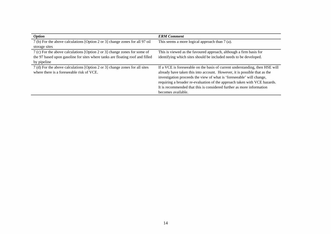
Option ERM Comment 7 (b) For the above calculations [Option 2 or 3] change zones for all 97 oil This seems a more logical approach than 7 (a). storage sites 7 (c) For the above calculations [Option 2 or 3] change zones for some of This is viewed as the favoured approach, although a firm basis for the 97 based upon gasoline for sites where tanks are floating roof and filled identifying which sites should be included needs to be developed. by pipeline 7 (d) For the above calculations [Option 2 or 3] change zones for all sites If a VCE is foreseeable on the basis of current understanding, then HSE will where there is a foreseeable risk of VCE. already have taken this into account. However, it is possible that as the
investigation proceeds the view of what is ‘foreseeable’ will change, requiring a broader re-evaluation of the approach taken with VCE hazards. It is recommended that this is considered further as more information becomes available.
14

Overall, it was judged that any revised approach should have regard for the current state of knowledge regarding events at Buncefield, and should be somewhat precautionary in nature. In summary, it was recommended that consideration be given to amendment of both the zones and the development sensitivity level definitions.
5.1 CHANGES TO LUP ZONES
It was decided that observations of the damage incurred at Buncefield could be used to estimate maximum ranges to damage levels of interest. These distances would then be used to establish LUP zone boundaries. For example, the inner zone distance would correspond to the maximum range to serious structural damage. Establishing zone boundaries on the basis of observed damage rather than an estimate of the overpressure required to cause the observed level of damage avoids the uncertainty inherent in the overpressure estimate.
An analytical approach to establishing LUP zones (e.g. by using an explosion model to calculate distances to overpressures of interest) is not considered feasible at present, owing to the lack of understanding of the explosion mechanism involved.
5.2 CHANGES TO SENSITIVITY LEVEL DEFINITIONS
In addition, the definition of Sensitivity Level 1 (S1) developments was revisited to ensure that the nature of the vapour cloud explosion hazard and the effect of such events on building occupants were addressed adequately.
15

6 DEVELOPMENT OF PROPOSALS FOR REVISED ARRANGEMENTS
The proposed revised arrangements have been developed by:
• Reviewing published HSE research on the effects of explosions (Jeffries et al., 1997; Galbraith, 1998), (see Appendix 1);
• Considering the levels of damage to buildings observed around the Buncefield site (see Appendix 2);
• Revisiting the justifications underlying the Sensitivity Level definitions for proposed developments in the light of the first two activities.
The review of published HSE research found that a model for predicting the effects of blast from VCEs on buildings and their occupants (Jeffries et al., 1997) contained flaws which raised questions over the validity of the model results. Further development of the model would be necessary to rectify these problems.
6.1 REVISION OF LUP ZONE BOUNDARIES
Some limited but useful data are available which correlate levels of building damage to the harm suffered by their occupants (Galbraith, 1998). These data result from observations of bomb damage sustained during the Second World War.
In conjunction with the observations of damage to buildings, the data have been used to form a judgement concerning the likelihood of harm (in broad terms) to the occupants of different buildings. Damaged buildings were assigned to one of four harm categories: high, medium, low and minimal. The first three of these categories correspond to the three harm levels used when performing a protection based assessment (see Section 2.1). The ‘minimal’ category indicates that the potential for harm to occupants arising from damage to the building was such that it would not be of interest for the purposes of setting LUP zone boundaries.
The distances to buildings in the different harm categories were measured and used to establish zone boundaries. This resulted in the proposed zone boundary distances displayed in Table 6. The process is described in detail in Appendix 3.
Table 6 Proposed Zone Boundaries
Zone Distance (m) Inner 250 Middle 300 Outer 400
16
6.2 REVISION OF SENSITIVITY LEVEL DEFINITIONS
The Buncefield explosion and subsequent fires resulted in significant damage to property; particularly to those buildings situated relatively close to the installation (see Appendix 2). For the Northgate and Fuji buildings, from the information available it seems likely that, had people been present in those parts of these buildings closest to the site, they would have been exposed to a level of harm presenting a significant likelihood of death (see Appendix 3).
These observations have prompted the author to review the HSE definitions of Sensitivity Level 1 developments, since such developments would not be advised against anywhere within the consultation distance, even within the inner zone (see Table 2). Hence such developments could, under existing arrangements, be placed at locations where levels of individual risk were relatively high.
Essentially Sensitivity Level 1 developments have been defined as:
• small examples of housing, holiday / hostel and retail / leisure developments (see Table 4); and,
• office, factories and workplaces for less than 100 occupants and less than 3 stories in height (see Table 3).
The justifications for placing these types of development into Sensitivity Level 1 are discussed below.
Throughout these discussions, it is important to note that the HSE calculates risk in terms of the individual risk of experiencing a ‘dangerous dose or worse’, as opposed to the individual risk of fatality (see Section 2.1). Exposure to a dangerous dose corresponds to approximately a 1-5% probability of fatality to a typical cross-section of the population (with only the most vulnerable or sensitive individuals becoming fatalities). However, the proportion of ‘or worse’ within the risk of dangerous dose or worse varies as a function of distance from an installation and with the hazards presented by the installation.
For most types of hazard, as the site of interest is approached the proportion of ‘or worse’ (e.g., fatality) within the risk of dangerous dose or worse is increased. Also, the proportion of ‘or worse’ tends to be higher with fire and explosion hazards than with most toxic hazards. Indeed, for some types of fire or explosion event (including a VCE like that experienced at Buncefield), in the near field the risk of dangerous dose or worse is almost entirely a risk of fatality.
6.2.1 Small housing, hotel / hostel and retail / leisure developments
Several smaller developments of various types are assigned to Sensitivity Level 1 as a result of an ‘exclusion’ from another Level (see Table 4). These include:
• housing developments for 1 or 2 dwellings; • holiday / hostel accommodation of less than 10 beds or 3 caravan / tent pitches; and, • retail / leisure development with less than 250 m2 total floor space.
17

For each of these development types, the justification given within the PADHI document (HSE, -) is that there is ‘minimal increase in numbers at risk’. A more detailed discussion of the justification is presented in HSE’s risk criteria document for land use planning (HSE, 1989). This document provides a second reason for not advising against such developments:
“the ‘dangerous dose’ would only be fatal for a small fraction of the population, and a fraction of the population of two houses is probably zero.” (HSE, 1989; para. 85).
Although this statement relates to small housing developments, the document makes it clear that holiday / hostel accommodation is placed in the same category as housing (HSE, 1989; para. 81); and retail / leisure development is assumed to be “similar in significance” to housing (HSE, 1989; para. 82).
These justifications relate to the increment of societal risk associated with a proposed development (the case societal risk). The first relates to the number of people exposed to the risk, the second to the numbers of people who might become fatalities if exposed to a dangerous dose.
For the first of the justifications given (‘minimal increase in numbers at risk’) it appears that the low case societal risk associated with such developments has been given greater weight than the relatively high individual risk to which people could be exposed. This arises from a tension between two of the stated principles of HSE’s involvement in land-use planning, that:
“The risk from a hazardous installation to an individual employee or member of the public should not be significant when compared with other risks to which he is exposed in everyday life.” (Advisory Committee on Major Hazards, 1984) para. 21;
and:
“The separation of a hazard from a built-up area need not mean… that the intervening land is completely sterilised or available only for agricultural purposes. Depending on the degree of hazard, it may be possible for it to be allocated for other purposes involving low population densities, including some industrial developments.” (Advisory Committee on Major Hazards, 1984), para. 84.
Under the current arrangements, the second of these principles overrides the first for some of those developments falling into Sensitivity Level 1. However, for a site with the potential for a VCE like that experienced at Buncefield, the risk of ‘dangerous dose or worse’ close to the site is likely to be almost entirely a risk of fatality. In view of this, it is proposed that for certain developments currently placed within Sensitivity Level 1, the balance between the two principles stated above is shifted in favour of the first, and that these developments should be assigned to Sensitivity Level 2.
The second justification is essentially that, in a small number of exposed people, it is probable that none of them would be particularly sensitive or vulnerable to the hazard in question. Therefore, if this group of people was exposed to a dangerous dose, it is unlikely that any fatalities would result. However, this argument does not consider the proportion of ‘or worse’ within the ‘dangerous dose or worse’. As discussed above, for a VCE like that experienced at
18
Buncefield, the ‘or worse’ proportion is likely to be high close to the event. Hence, even amongst a small group of people, some fatalities could result. This supports the proposal that the types of developments in question should be re-assigned to Sensitivity Level 2.
This issues discussed in this Section have broader implications and are not specifically related to the Buncefield accident or the VCE hazard. However, it is considered prudent to address them in the context of this study, in view of the significant likelihood of fatality to which people close to sites of interest could be exposed.
6.2.2 Workplaces
The first part of the justification given for assigning workplaces to Sensitivity Level 1 is that these are ‘places where the occupants will be fit and healthy, and could be organised easily for emergency action’ (see Table 3).
The first part of the justification (‘occupants fit and healthy’) appears to suggest that amongst a group of workers, it is likely that the proportion that could be considered particularly sensitive or vulnerable would be lower than in the population at large. Therefore, if this group of workers was exposed to a dangerous dose, the resulting number of fatalities would probably be lower than for a group of the same size but representing a ‘typical’ cross-section of the general population.
However, as with one of the justifications discussed in the previous Section, this argument does not consider the proportion of ‘or worse’ within the ‘dangerous dose or worse’. As discussed above, for a VCE like that experienced at Buncefield, the ‘or worse’ proportion is likely to be high close to the event. Hence, even amongst a ‘fit and healthy’ group of people, some fatalities could result.
The second part of the justification appears to be that the risk to people in a workplace would be significantly reduced as a result of taking emergency action. This assumes that:
• effective emergency action (such as evacuation or sheltering) is possible; and, • there is sufficient time for this action to be taken.
With regard to the first of these points it is not clear what would constitute effective emergency action for occupants of workplaces close to a site presenting a VCE hazard. Evacuation of building occupants could place them in the flammable cloud. However, remaining within a building could place the occupants at greater risk of injury from blast effects.
Secondly, even if some kind of emergency action was possible, a VCE could occur rapidly, with little or no opportunity for raising the alarm.
In view of this, it is recommended that consideration is given to alteration of the definition of Sensitivity Level 1 developments within the revised arrangements. A more detailed discussion of the case societal risk aspects of workplace developments is presented in Appendix 4.
19

6.2.3 Summary of Recommendations
The recommended alterations to the Sensitivity Level definitions are as follows:
• all workplaces that are routinely occupied for a significant proportion of the time (i.e. – offices and factories), regardless of size, are re-assigned to Level 2;
• workplaces or areas that are visited intermittently (warehouses, timber yards, outdoor storage areas, haulage depots, farm buildings) with no associated office facilities and car parks with no associated amenities remain in Level 1;
• housing developments of 1 or 2 dwelling units are re-assigned to Level 2; • smaller hotel / holiday / hostel accommodation is assigned to Level 2; and, • retail development with less than 250 m2 floor space is assigned to Level 2.
6.3 OPTIONS
Since the proposed revised zone boundaries are considerably larger than those normally encountered for those sites of interest (see Table 6), the view could be taken that it would be sufficiently precautionary to change the zone boundaries without changing the Sensitivity Levels. This results in two options for revised arrangements:
• Option A: Increase the size of the LUP zones only; or, • Option B: Increase the size of the LUP zones and revise the development sensitivity
levels.
6.4 APPLICATION
It is recommended that the proposed arrangements are applied to those sites which are similar to Buncefield in a number of important respects. These similarities would indicate that on the basis of what is known at present, the site has the potential to give rise to a VCE.
If implemented, it is recommended that the proposed arrangements are applied to sites with the following characteristics:
• the site is classed as either ‘upper tier’ or ‘lower tier’ under the Control of major Accident Hazards Regulations 1999 (the COMAH Regulations);
• the site stores petroleum in vertical, cylindrical, non-refrigerated above-ground storage tanks with side walls greater than 5 m in height; and,
• the filling rate of the storage tanks is greater than 100 m3 / hour.
These criteria align with those used by the Buncefield Standards Task Group, a joint COMAH Competent Authority and Industry committee (HSE, 2006).
20

7 IMPACT OF THE PROPOSED ARRANGEMENTS
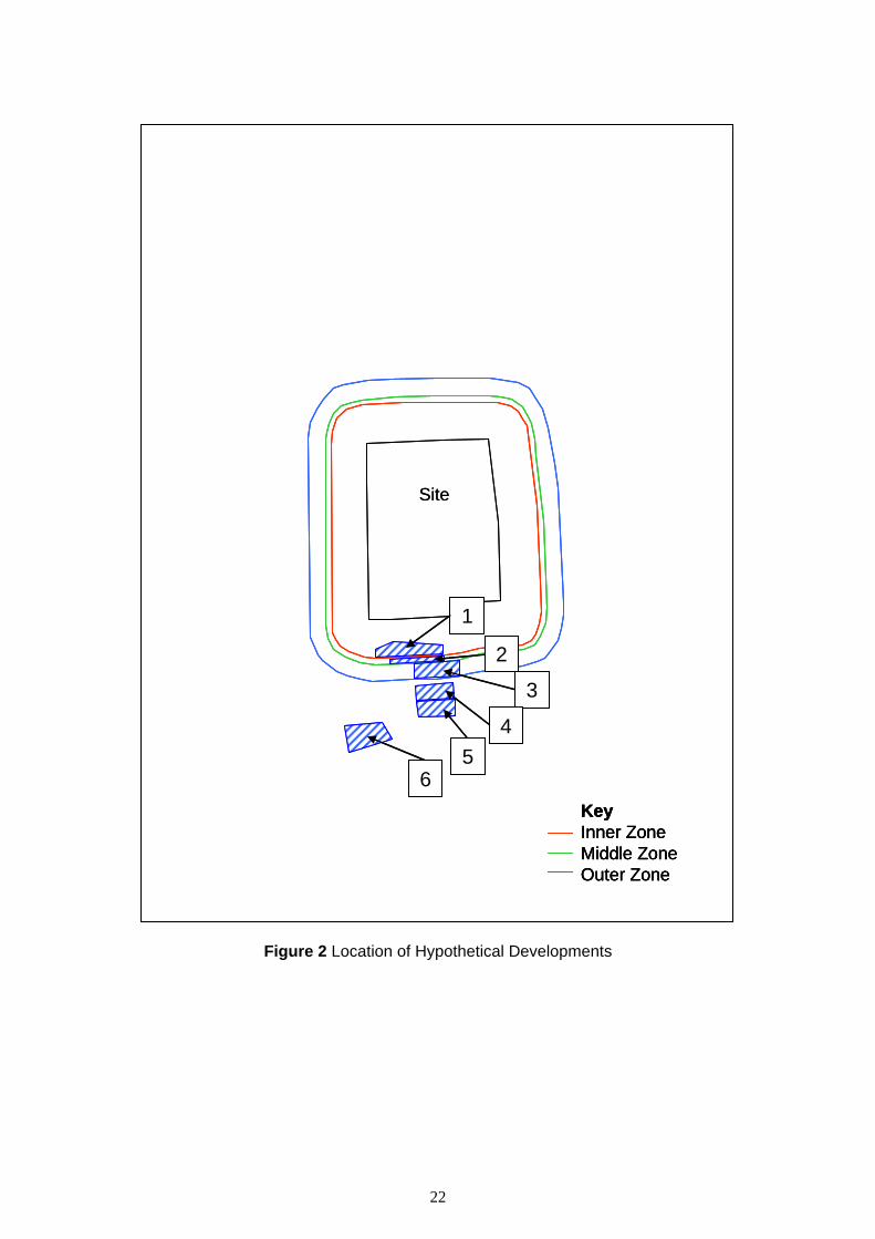
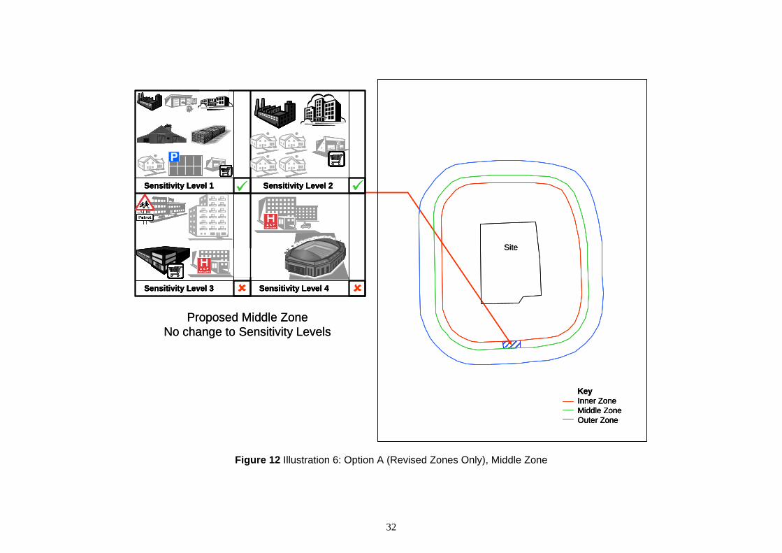
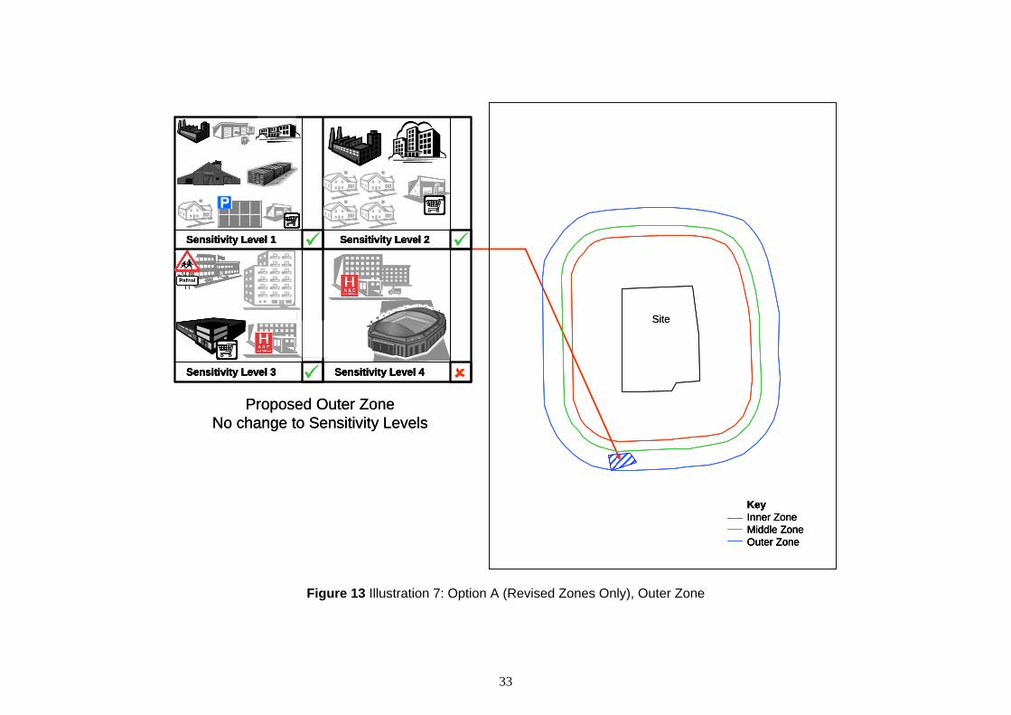
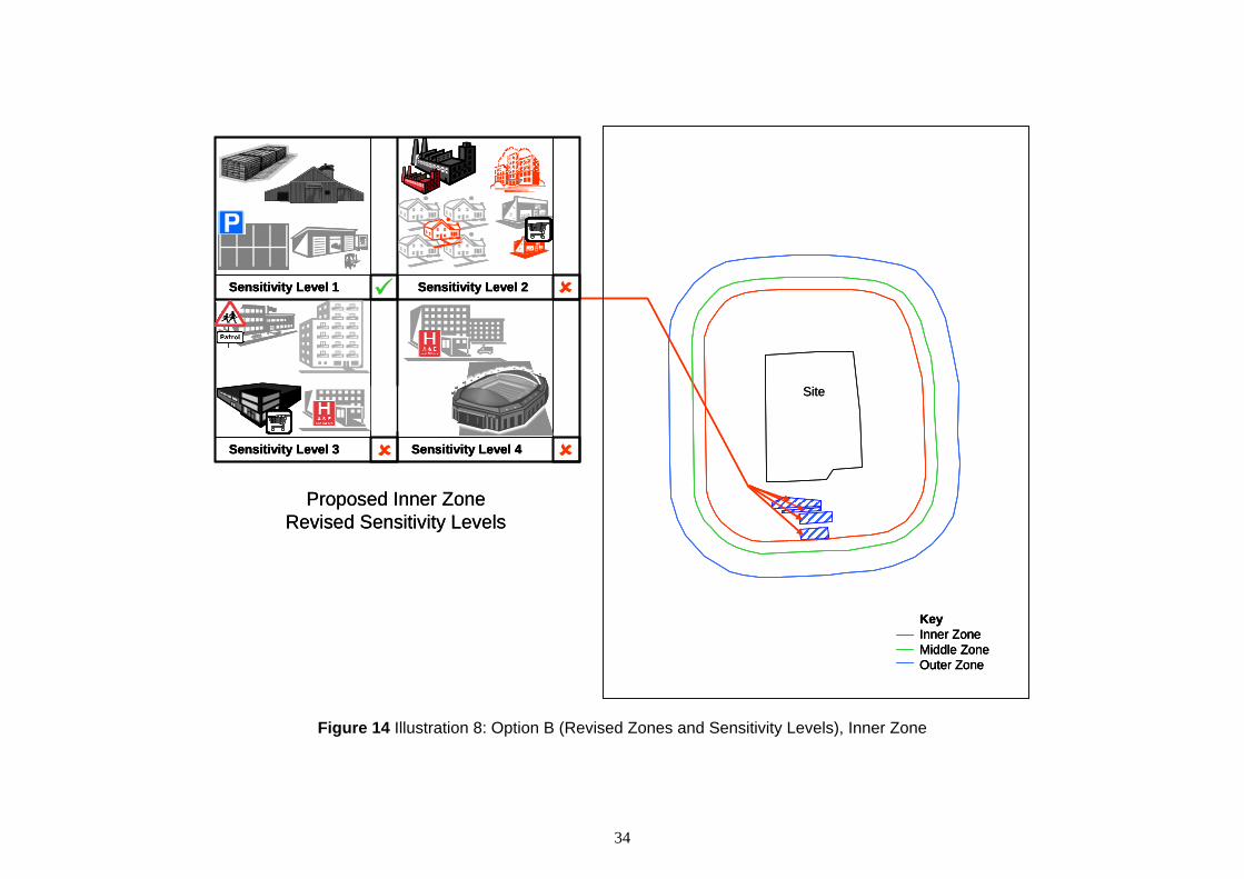
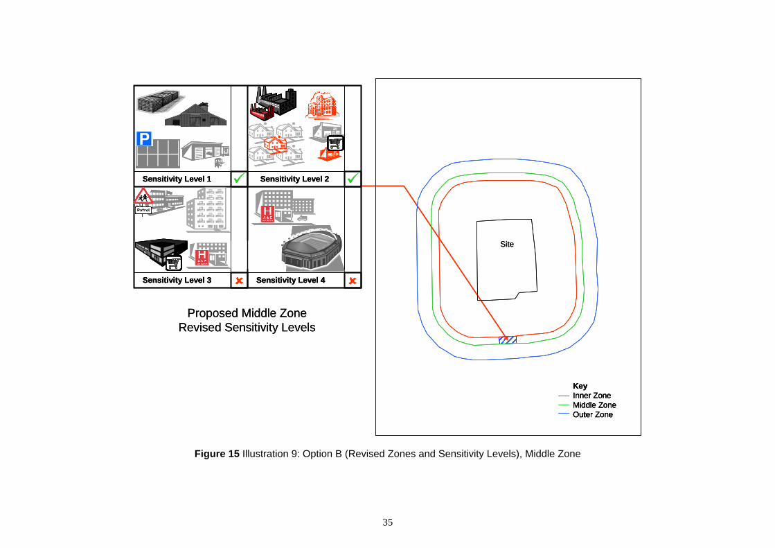
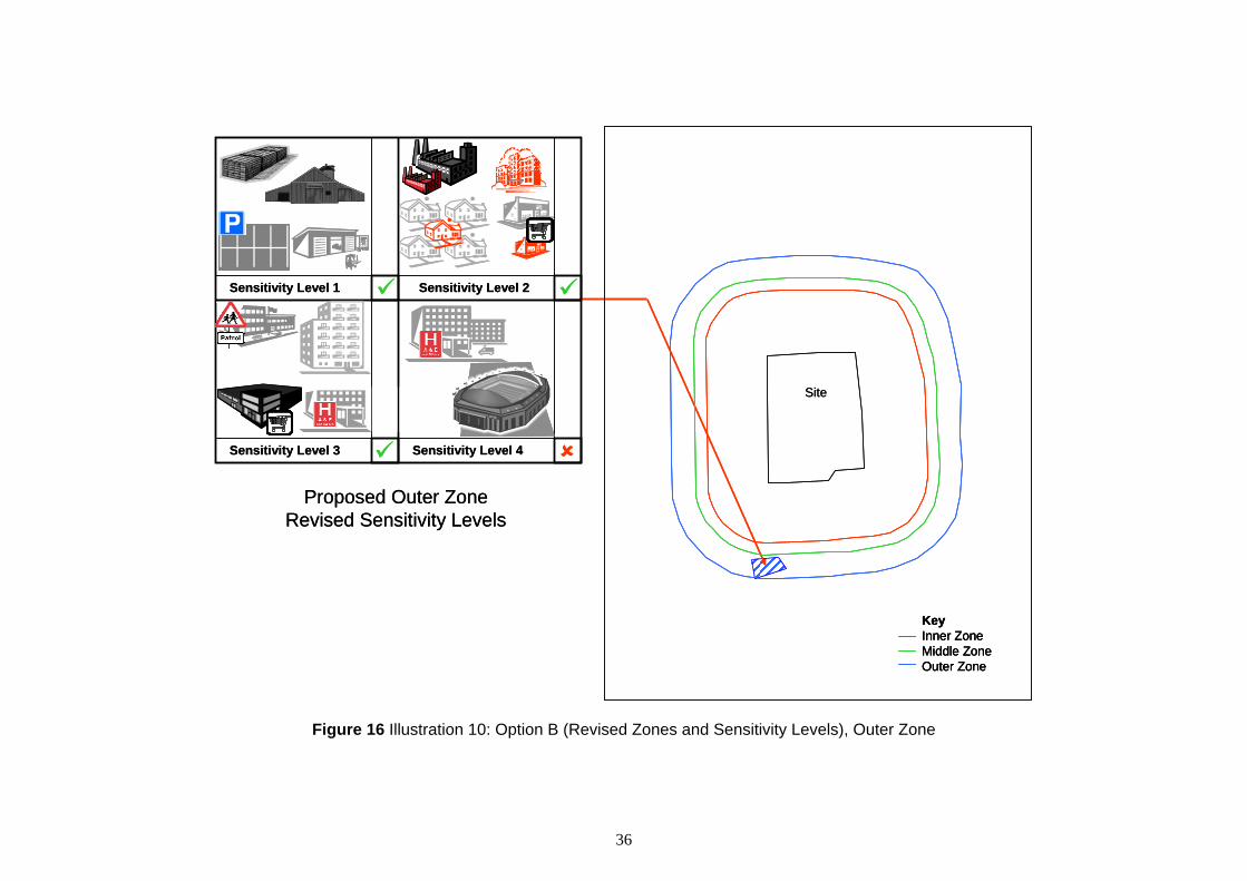
The impact of the proposed options has been illustrated by considering a series of hypothetical developments at different locations around a hypothetical site. Under the current system the hypothetical site has the inner, middle and outer zone boundaries set at distances of 120 m, 135 m and 185 m respectively (these distances correspond to those currently set for the Buncefield site). The proposed revisions to the system would increase these distances to those presented in Table 6. The selected locations are displayed in Figure 2. With regard to these locations, it should be noted that:
• Location 1 is within the current inner zone; • Location 2 is within the current middle zone; • Location 3 is within the current outer zone; and, • Locations 4, 5 and 6 are all outside the current consultation distance.
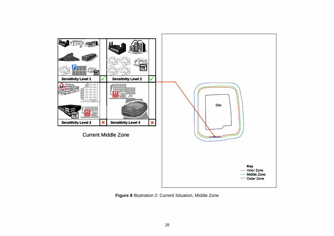
Although the current middle zone is quite ‘narrow’, it has been assumed for the purposes of the illustrations that Location 2 is able to accommodate the hypothetical developments considered (1).
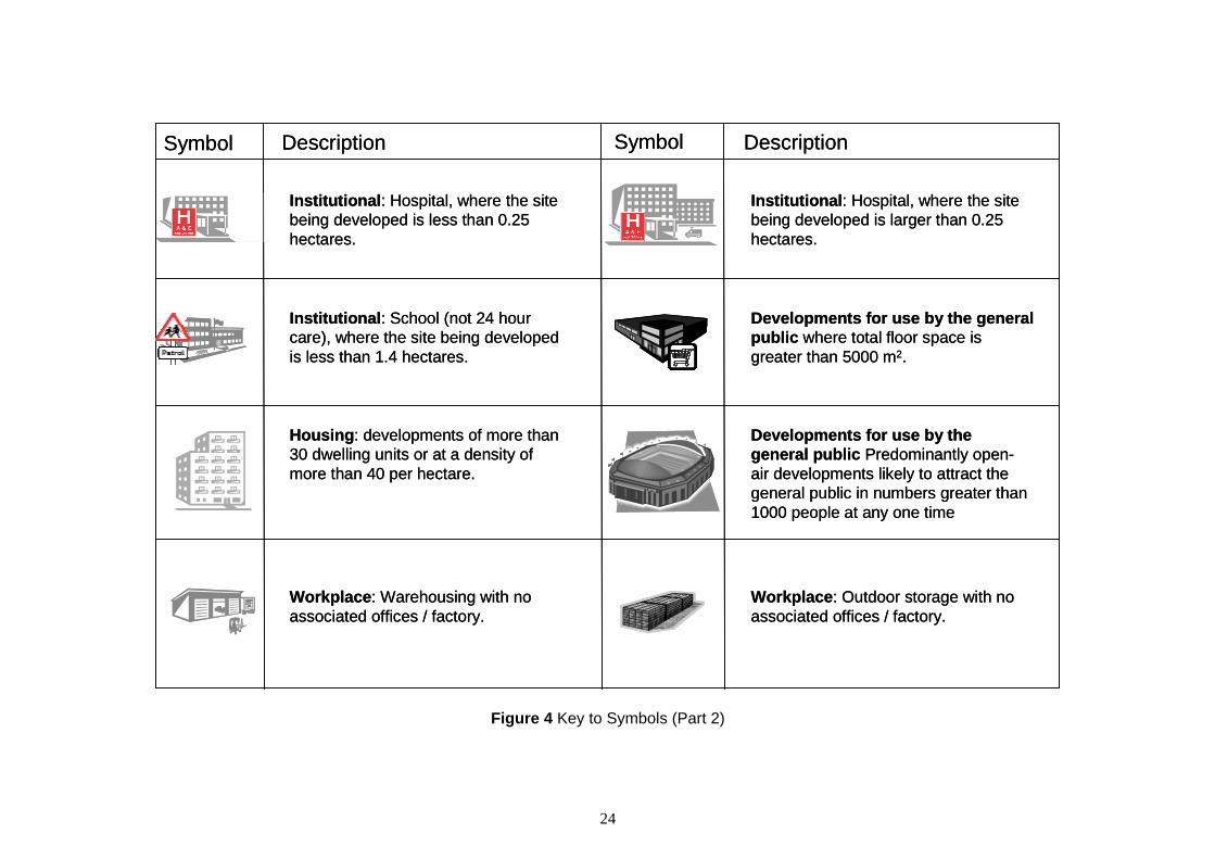
Different types of development have been represented by symbols. A key to the symbols used in the illustrations is presented in Figure 3, Figure 4 and Figure 5.
The illustrations are provided in the following figures:
• Figure 6 Comparison of Existing and Revised LUP Zones; • Figure 7 Illustration 1: Current Situation, Inner Zone; • Figure 8 Illustration 2: Current Situation, Middle Zone; • Figure 9 Illustration 3: Current Situation, Outer Zone; • Figure 10 Illustration 4: Current Situation, Beyond CD; • Figure 11 Illustration 5: Option A (Revised Zones Only), Inner Zone; • Figure 12 Illustration 6: Option A (Revised Zones Only), Middle Zone; • Figure 13 Illustration 7: Option A (Revised Zones Only), Outer Zone; • Figure 14 Illustration 8: Option B (Revised Zones and Sensitivity Levels), Inner Zone; • Figure 15 Illustration 9: Option B (Revised Zones and Sensitivity Levels), Middle
Zone; and, • Figure 16 Illustration 10: Option B (Revised Zones and Sensitivity Levels), Outer Zone.
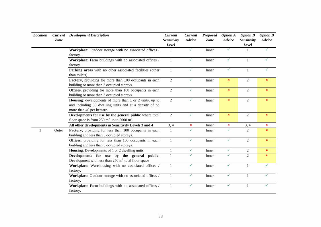
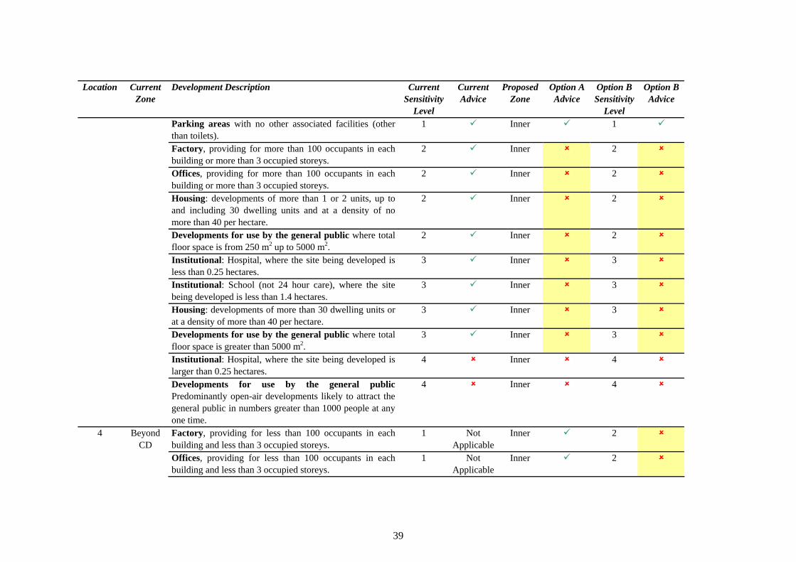
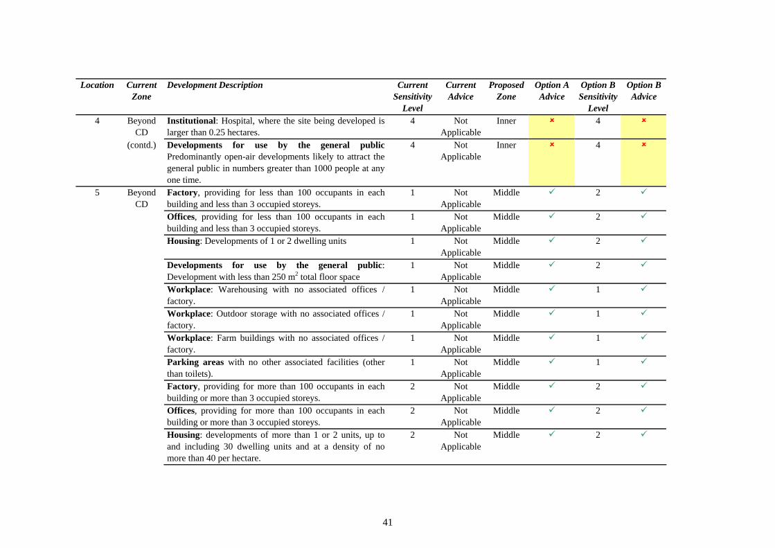
The illustrations are also summarised in Table 7, where differences with the current system are shown by highlighted cells.
(1) There are additional rules within the current policy to address developments which straddle zone boundaries.
21
1
2
3
45
6Key Inner Zone Middle Zone Outer Zone
Site
1
2
3
4 5
6 KeyInner ZoneMiddle ZoneOuter Zone
KeyInner ZoneMiddle ZoneOuter Zone
Site
Figure 2 Location of Hypothetical Developments
22

SymboSymboll DescriptionDescription SymbolSymbol DescriptionDescription
Factory, providing for less than 100Factory, providing for less than 100occupants in each buildoccupants in each buildiing and less thanng and less than3 occupied storeys.3 occupied storeys.
Factory, providing for more than 100Factory, providing for more than 100 occupants in each building or more than 3occupants in each building or more than 3occupoccupiied storeys.ed storeys.
Offices, provOffices, proviiddiing for less than 100ng for less than 100 occupants in each buildoccupants in each buildiing and less thanng and less than3 occupied storeys.3 occupied storeys.
Offices, provOffices, proviiddiing for more than 100ng for more than 100occupants in each building or more than 3occupants in each building or more than 3occupoccupiied storeys.ed storeys.
Housing: DeveHousing: Devellopments of 1 or 2opments of 1 or 2 Housing: developments of more thanHousing: developments of more thandwelling unitsdwelling units 1 or 2 un1 or 2 uniits, up to andts, up to and iincncllududiing 30ng 30
dwedwelllliing unng uniits and at a density of nots and at a density of no more than 40 per hectare.more than 40 per hectare.
Developments for use by the generalDevelopments for use by the general Developments for use by the generalDevelopments for use by the general public: Development wpublic: Development wiith less thanth less than public where total floor space is frompublic where total floor space is from250 m2 total floor space250 m2 total floor space 250 m2 up to 5000 m2250 m2 up to 5000 m2..
Figure 3 Key to Symbols (Part 1)
23
24
Symbol SymbolDescription Description
Institutional: Hospital, where the site being developed is less than 0.25 hectares.
Institutional: Hospital, where the site being developed is larger than 0.25 hectares.
Institutional: School (not 24 hour care), where the site being developed is less than 1.4 hectares.
Developments for use by the general public where total floor space is greater than 5000 m2.
Housing: developments of more than 30 dwelling units or at a density of more than 40 per hectare.
Developments for use by the general public Predominantly open-air developments likely to attract the general public in numbers greater than 1000 people at any one time
Workplace: Warehousing with no associated offices / factory.
Workplace: Outdoor storage with no associated offices / factory.
Figure 4 Key to Symbols (Part 2)

SymboSymboll DescrDescriiptptiionon SymboSymboll DescriptionDescription
Parking areas wParking areas wiith no otherth no other Workplace: Farm buildWorkplace: Farm buildiings with nongs with no associated facilitiesassociated facilities ((other thanother than associated officesassociated offices // factory.factory.totoiillets).ets).
Factory, regardless of number ofFactory, regardless of number of Offices, regardOffices, regardlless of number ofess of number ofoccupants in each buildoccupants in each buildiing and numberng and number occupants in each buildoccupants in each buildiing andng andof occupied storeys.of occupied storeys. number of occupied storeys.number of occupied storeys.
Housing: developments of up to andHousing: developments of up to andincluding 30 dwelling unincluding 30 dwelling uniits and at ats and at adensity of no more than 40 perdensity of no more than 40 per hectare. Includes small developmentshectare. Includes small developmentsof 1-2 unof 1-2 uniitsts
Developments for use by the generalDevelopments for use by the general public all developments where totalpublic all developments where totalfflloor space is up to 5000 m2. Includesoor space is up to 5000 m2. Includesdevelopments wdevelopments wiithth lless than 250 m2ess than 250 m2
fflloor space.oor space.
Figure 5 Key to Symbols (Part 3)
25

SiteSite
Existing Zones Revised Zones
SiteSite
Existing Zones Revised Zones
Figure 6 Comparison of Existing and Revised LUP Zones
26

27
9 8
88
Current Inner Zone
Sensitivity Level 1 Sensitivity Level 2
Sensitivity Level 3 Sensitivity Level 4
KeyInner ZoneMiddle ZoneOuter Zone
Site
9 8
88
Current Inner Zone
Sensitivity Level 1 Sensitivity Level 2
Sensitivity Level 3 Sensitivity Level 4
Sensitivity Level 1 Sensitivity Level 2
Sensitivity Level 3 Sensitivity Level 4
Sensitivity Level 1 Sensitivity Level 2
Sensitivity Level 3 Sensitivity Level 4
KeyInner ZoneMiddle ZoneOuter Zone
KeyInner ZoneMiddle ZoneOuter Zone
Site
Figure 7 Illustration 1: Current Situation, Inner Zone
28
9
88
Current Middle Zone
Sensitivity Level 1 Sensitivity Level 2
Sensitivity Level 3 Sensitivity Level 4
9
KeyInner ZoneMiddle ZoneOuter Zone
Site
9
88
Current Middle Zone
Sensitivity Level 1 Sensitivity Level 2
Sensitivity Level 3 Sensitivity Level 4
Sensitivity Level 1 Sensitivity Level 2
Sensitivity Level 3 Sensitivity Level 4
Sensitivity Level 1 Sensitivity Level 2
Sensitivity Level 3 Sensitivity Level 4
9
KeyInner ZoneMiddle ZoneOuter Zone
KeyInner ZoneMiddle ZoneOuter Zone
Site
Figure 8 Illustration 2: Current Situation, Middle Zone

29
9 9
8
Current Outer Zone
9
Sensitivity Level 1 Sensitivity Level 2
Sensitivity Level 3 Sensitivity Level 4
KeyInner ZoneMiddle ZoneOuter Zone
Site
9 9
8
Current Outer Zone
9
Sensitivity Level 1 Sensitivity Level 2
Sensitivity Level 3 Sensitivity Level 4
Sensitivity Level 1 Sensitivity Level 2
Sensitivity Level 3 Sensitivity Level 4
Sensitivity Level 1 Sensitivity Level 2
Sensitivity Level 3 Sensitivity Level 4
KeyInner ZoneMiddle ZoneOuter Zone
KeyInner ZoneMiddle ZoneOuter Zone
Site
Figure 9 Illustration 3: Current Situation, Outer Zone

Beyond the Current CDBeyond the Current CDNo consultation with HSE requiredNo consultation with HSE required
Key Inner Zone Middle Zone Outer Zone
Site
KeyInner ZoneMiddle ZoneOuter Zone
KeyInner ZoneMiddle ZoneOuter Zone
Site
Figure 10 Illustration 4: Current Situation, Beyond CD
30

31
9 8
88
Proposed Inner ZoneNo change to Sensitivity Levels
Sensitivity Level 1 Sensitivity Level 2
Sensitivity Level 3 Sensitivity Level 4
Sensitivity Level 1 Sensitivity Level 2
Sensitivity Level 3 Sensitivity Level 4
KeyInner ZoneMiddle ZoneOuter Zone
Site
9 8
88
Proposed Inner ZoneNo change to Sensitivity Levels
Sensitivity Level 1 Sensitivity Level 2
Sensitivity Level 3 Sensitivity Level 4
Sensitivity Level 1 Sensitivity Level 2
Sensitivity Level 3 Sensitivity Level 4
Sensitivity Level 1 Sensitivity Level 2
Sensitivity Level 3 Sensitivity Level 4
Sensitivity Level 1 Sensitivity Level 2
Sensitivity Level 3 Sensitivity Level 4
Sensitivity Level 1 Sensitivity Level 2
Sensitivity Level 3 Sensitivity Level 4
Sensitivity Level 1 Sensitivity Level 2
Sensitivity Level 3 Sensitivity Level 4
KeyInner ZoneMiddle ZoneOuter Zone
KeyInner ZoneMiddle ZoneOuter Zone
Site
Figure 11 Illustration 5: Option A (Revised Zones Only), Inner Zone
32
9
8
9
8
Proposed Middle ZoneNo change to Sensitivity Levels
Sensitivity Level 1 Sensitivity Level 2
Sensitivity Level 3 Sensitivity Level 4
KeyInner ZoneMiddle ZoneOuter Zone
Site
9
8
9
8
Proposed Middle ZoneNo change to Sensitivity Levels
Sensitivity Level 1 Sensitivity Level 2
Sensitivity Level 3 Sensitivity Level 4
Sensitivity Level 1 Sensitivity Level 2
Sensitivity Level 3 Sensitivity Level 4
Sensitivity Level 1 Sensitivity Level 2
Sensitivity Level 3 Sensitivity Level 4
KeyInner ZoneMiddle ZoneOuter Zone
KeyInner ZoneMiddle ZoneOuter Zone
Site
Figure 12 Illustration 6: Option A (Revised Zones Only), Middle Zone
33
9
8
Proposed Outer ZoneNo change to Sensitivity Levels
9
9
Sensitivity Level 1 Sensitivity Level 2
Sensitivity Level 3 Sensitivity Level 4
KeyInner ZoneMiddle ZoneOuter Zone
Site
9
8
Proposed Outer ZoneNo change to Sensitivity Levels
9
9
Sensitivity Level 1 Sensitivity Level 2
Sensitivity Level 3 Sensitivity Level 4
Sensitivity Level 1 Sensitivity Level 2
Sensitivity Level 3 Sensitivity Level 4
Sensitivity Level 1 Sensitivity Level 2
Sensitivity Level 3 Sensitivity Level 4
KeyInner ZoneMiddle ZoneOuter Zone
KeyInner ZoneMiddle ZoneOuter Zone
Site
Figure 13 Illustration 7: Option A (Revised Zones Only), Outer Zone
34
9 8
88
Proposed Inner ZoneRevised Sensitivity Levels
Sensitivity Level 1 Sensitivity Level 2
Sensitivity Level 3 Sensitivity Level 4
KeyInner ZoneMiddle ZoneOuter Zone
Site
9 8
88
Proposed Inner ZoneRevised Sensitivity Levels
Sensitivity Level 1 Sensitivity Level 2
Sensitivity Level 3 Sensitivity Level 4
Sensitivity Level 1 Sensitivity Level 2
Sensitivity Level 3 Sensitivity Level 4
KeyInner ZoneMiddle ZoneOuter Zone
KeyInner ZoneMiddle ZoneOuter Zone
Site
Figure 14 Illustration 8: Option B (Revised Zones and Sensitivity Levels), Inner Zone
35
9
8
9
8
Proposed Middle ZoneRevised Sensitivity Levels
Sensitivity Level 1 Sensitivity Level 2
Sensitivity Level 3 Sensitivity Level 4
KeyInner ZoneMiddle ZoneOuter Zone
Site
9
8
9
8
Proposed Middle ZoneRevised Sensitivity Levels
Sensitivity Level 1 Sensitivity Level 2
Sensitivity Level 3 Sensitivity Level 4
Sensitivity Level 1 Sensitivity Level 2
Sensitivity Level 3 Sensitivity Level 4
KeyInner ZoneMiddle ZoneOuter Zone
KeyInner ZoneMiddle ZoneOuter Zone
Site
Figure 15 Illustration 9: Option B (Revised Zones and Sensitivity Levels), Middle Zone
36
9
8
Proposed Outer ZoneRevised Sensitivity Levels
9
9
Sensitivity Level 1 Sensitivity Level 2
Sensitivity Level 3 Sensitivity Level 4
KeyInner ZoneMiddle ZoneOuter Zone
Site
9
8
Proposed Outer ZoneRevised Sensitivity Levels
9
9
Sensitivity Level 1 Sensitivity Level 2
Sensitivity Level 3 Sensitivity Level 4
KeyInner ZoneMiddle ZoneOuter Zone
KeyInner ZoneMiddle ZoneOuter Zone
Site
Figure 16 Illustration 10: Option B (Revised Zones and Sensitivity Levels), Outer Zone

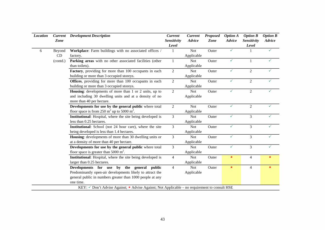
Table 7 Summary of Illustrations
Location Current Development Description Current Current Proposed Option A Option B Option B Zone Sensitivity Advice Zone Advice Sensitivity Advice
Level Level 1 1 9 9 2 8
Offices 1 9 9 2 8
1 9 9 2 8 for use by the :
21 9 9 2 8
Inner Factory, providing for less than 100 occupants in each building and less than 3 occupied storeys.
Inner
, providing for less than 100 occupants in each building and less than 3 occupied storeys.
Inner
Housing: Developments of 1 or 2 dwelling units Inner Developments general publicDevelopment with less than 250 m total floor space
Inner
Workplace: Warehousing with no associated offices / 1 9 Inner 9 1 9 factory. Workplace: Outdoor storage with no associated offices / 1 9 Inner 9 1 9 factory. Workplace: Farm buildings with no associated offices / 1 9 Inner 9 1 9 factory. Parking areas with no other associated facilities (other 1 9 Inner 9 1 9 than toilets). All other developments in Sensitivity Levels 2, 3 and 4 2, 3, 4 8 Inner 8 2, 3, 4 8
2 1 9 9 2 8
Offices 1 9 9 2 8
1 9 9 2 8 for use by the :
21 9 9 2 8
Middle Factory, providing for less than 100 occupants in each building and less than 3 occupied storeys.
Inner
, providing for less than 100 occupants in each building and less than 3 occupied storeys.
Inner
Housing: Developments of 1 or 2 dwelling units Inner Developments general publicDevelopment with less than 250 m total floor space
Inner
Workplace: Warehousing with no associated offices / 1 9 Inner 9 1 factory.
37
9
Location Current Zone
Development Description Current Sensitivity
Level
Current Advice
Proposed Zone
Option A Advice
Option B Sensitivity
Level
Option B Advice
Workplace: Outdoor storage with no associated offices / factory.
1 9 Inner 9 1 9
Workplace: Farm buildings with no associated offices / factory.
1 9 Inner 9 1 9
Parking areas with no other associated facilities (other than toilets).
1 9 Inner 9 1 9
2 9 8 2 8
Offices 2 9 8 2 8
2 9 8 2 8
2 2 . 2 9 8 2 8
Factory, providing for more than 100 occupants in each building or more than 3 occupied storeys.
Inner
, providing for more than 100 occupants in each building or more than 3 occupied storeys.
Inner
Housing: developments of more than 1 or 2 units, up to and including 30 dwelling units and at a density of no more than 40 per hectare.
Inner
Developments for use by the general public where total floor space is from 250 m up to 5000 m
Inner
All other developments in Sensitivity Levels 3 and 4 3, 4 8 Inner 8 3, 4 3 1 9 9 2 8
Offices 1 9 9 2 8
1 9 9 2 8 for use by the :
21 9 9 2 8
Outer Factory, providing for less than 100 occupants in each building and less than 3 occupied storeys.
Inner
, providing for less than 100 occupants in each building and less than 3 occupied storeys.
Inner
Housing: Developments of 1 or 2 dwelling units Inner Developments general publicDevelopment with less than 250 m total floor space
Inner
Workplace: Warehousing with no associated offices / factory.
1 9 Inner 9 1 9
Workplace: Outdoor storage with no associated offices / factory.
1 9 Inner 9 1 9
Workplace: Farm buildings with no associated offices / factory.
1 9 Inner 9 1 9
38
8
Location Current Development Description Current Current Proposed Option A Option B Option B Zone Sensitivity Advice Zone Advice Sensitivity Advice
Level Level Parking areas with no other associated facilities (other 1 9 Inner 9 1 9 than toilets).
2 9 8 2 8
Offices 2 9 8 2 8
2 9 8 2 8
2 2 . 2 9 8 2 8
Institutional 3 9 8 3 8
Institutional ) 3 9 8 3 8
3 9 8 3 8
2 . 3 9 8 3 8
Factory, providing for more than 100 occupants in each building or more than 3 occupied storeys.
Inner
, providing for more than 100 occupants in each building or more than 3 occupied storeys.
Inner
Housing: developments of more than 1 or 2 units, up to and including 30 dwelling units and at a density of no more than 40 per hectare.
Inner
Developments for use by the general public where total floor space is from 250 m up to 5000 m
Inner
: Hospital, where the site being developed is less than 0.25 hectares.
Inner
: School (not 24 hour care , where the site being developed is less than 1.4 hectares.
Inner
Housing: developments of more than 30 dwelling units or at a density of more than 40 per hectare.
Inner
Developments for use by the general public where total floor space is greater than 5000 m
Inner
Institutional: Hospital, where the site being developed is 4 8 Inner 8 4 8 larger than 0.25 hectares. Developments for use by the general public 4 8 Inner 8 4 8 Predominantly open-air developments likely to attract the general public in numbers greater than 1000 people at any one time.
4CD
1 Not 9 2 8
Offices 1 Not 9 2 8
Beyond Factory, providing for less than 100 occupants in each building and less than 3 occupied storeys. Applicable
Inner
, providing for less than 100 occupants in each building and less than 3 occupied storeys. Applicable
Inner
39

Location Current Development Description Current Current Proposed Option A Option B Option B Zone Sensitivity Advice Zone Advice Sensitivity Advice
Level Level 4
CD 1 9 2 8
for use by the : 2
1 Not 9 2 8
Beyond Housing: Developments of 1 or 2 dwelling units Not Applicable
Inner
(contd.) Developments general publicDevelopment with less than 250 m total floor space Applicable
Inner
Workplace: Warehousing with no associated offices / 1 Not Inner 9 1 9 factory. Applicable Workplace: Outdoor storage with no associated offices / 1 Not Inner 9 1 9 factory. Applicable Workplace: Farm buildings with no associated offices / 1 Not Inner 9 1 9 factory. Applicable Parking areas with no other associated facilities (other 1 Not Inner 9 1 9 than toilets). Applicable
2 Not 8 2 8
Offices 2 Not 8 2 8
2 Not 8 2 8
2 2 . 2 Not 8 2 8
Institutional 3 Not 8 3 8
Institutional ) 3 Not 8 3 8
3 Not 8 3 8
2 . 3 Not 8 3 8
Factory, providing for more than 100 occupants in each building or more than 3 occupied storeys. Applicable
Inner
, providing for more than 100 occupants in each building or more than 3 occupied storeys. Applicable
Inner
Housing: developments of more than 1 or 2 units, up to and including 30 dwelling units and at a density of no more than 40 per hectare.
Applicable Inner
Developments for use by the general public where total floor space is from 250 m up to 5000 m Applicable
Inner
: Hospital, where the site being developed is less than 0.25 hectares. Applicable
Inner
: School (not 24 hour care , where the site being developed is less than 1.4 hectares. Applicable
Inner
Housing: developments of more than 30 dwelling units or at a density of more than 40 per hectare. Applicable
Inner
Developments for use by the general public where total floor space is greater than 5000 m Applicable
Inner
40
Location Current Development Description Current Current Proposed Option A Option B Option B Zone Sensitivity Advice Zone Advice Sensitivity Advice
Level Level 4
CD Institutional 4 Not 8 4 8
for use by the public 4 Not 8 4 8
Beyond : Hospital, where the site being developed is larger than 0.25 hectares. Applicable
Inner
(contd.) Developments general Predominantly open-air developments likely to attract the general public in numbers greater than 1000 people at any one time.
Applicable Inner
5 Beyond Factory, providing for less than 100 occupants in each 1 Not Middle 9 2 9 CD building and less than 3 occupied storeys. Applicable
Offices, providing for less than 100 occupants in each 1 Not Middle 9 2 9 building and less than 3 occupied storeys. Applicable Housing: Developments of 1 or 2 dwelling units 1 Not Middle 9 2 9
Applicable Developments for use by the general public: Development with less than 250 m2 total floor space
1 Not Applicable
Middle 9 2 9
Workplace: Warehousing with no associated offices / 1 Not Middle 9 1 9 factory. Applicable Workplace: Outdoor storage with no associated offices / 1 Not Middle 9 1 9 factory. Applicable Workplace: Farm buildings with no associated offices / 1 Not Middle 9 1 9 factory. Applicable Parking areas with no other associated facilities (other 1 Not Middle 9 1 9 than toilets). Applicable Factory, providing for more than 100 occupants in each 2 Not Middle 9 2 9 building or more than 3 occupied storeys. Applicable Offices, providing for more than 100 occupants in each 2 Not Middle 9 2 9 building or more than 3 occupied storeys. Applicable Housing: developments of more than 1 or 2 units, up to 2 Not Middle 9 2 9 and including 30 dwelling units and at a density of no Applicable more than 40 per hectare.
41

Location Current Development Description Current Current Proposed Option A Option B Option B Zone Sensitivity Advice Zone Advice Sensitivity Advice
Level Level 5 Beyond
CD Developments for use by the general public where total floor space is from 250 m2 up to 5000 m2 .
2 Not Applicable
Middle 9 2 9
Institutional 3 Not 8 3 8
Institutional ) 3 Not 8 3 8
3 Not 8 3 8
2 . 3 Not 8 3 8
Institutional 4 Not 8 4 8
for use by the public 4 Not 8 4 8
(contd.) : Hospital, where the site being developed is less than 0.25 hectares. Applicable
Middle
: School (not 24 hour care , where the site being developed is less than 1.4 hectares. Applicable
Middle
Housing: developments of more than 30 dwelling units or at a density of more than 40 per hectare. Applicable
Middle
Developments for use by the general public where total floor space is greater than 5000 m Applicable
Middle
: Hospital, where the site being developed is larger than 0.25 hectares. Applicable
Middle
Developments general Predominantly open-air developments likely to attract the general public in numbers greater than 1000 people at any one time.
Applicable Middle
6 Beyond Factory, providing for less than 100 occupants in each 1 Not Outer 9 2 9 CD building and less than 3 occupied storeys. Applicable
Offices, providing for less than 100 occupants in each 1 Not Outer 9 2 9 building and less than 3 occupied storeys. Applicable Housing: Developments of 1 or 2 dwelling units 1 Not Outer 9 2 9
Applicable Developments for use by the general public: Development with less than 250 m2 total floor space
1 Not Applicable
Outer 9 2 9
Workplace: Warehousing with no associated offices / 1 Not Outer 9 1 9 factory. Applicable Workplace: Outdoor storage with no associated offices / 1 Not Outer 9 1 9 factory. Applicable
42
Location Current Zone
Development Description Current Sensitivity
Level
Current Advice
Proposed Zone
Option A Advice
Option B Sensitivity
Level
Option B Advice
6 Beyond CD
Workplace: Farm buildings with no associated offices / factory.
1 Not Applicable
Outer 9 1 9
(contd.) Parking areas with no other associated facilities (other than toilets).
1 Not Applicable
Outer 9 1 9
Factory, providing for more than 100 occupants in each building or more than 3 occupied storeys.
2 Not Applicable
Outer 9 2 9
Offices, providing for more than 100 occupants in each building or more than 3 occupied storeys. Housing: developments of more than 1 or 2 units, up to and including 30 dwelling units and at a density of no more than 40 per hectare. Developments for use by the general public where total floor space is from 250 m2 up to 5000 m2 . Institutional: Hospital, where the site being developed is less than 0.25 hectares.
2
2
2
3
Not Applicable
Not Applicable
Not Applicable
Not Applicable
Outer
Outer
Outer
Outer
9
9
9
9
2
2
2
3
9
9
9
9
Institutional: School (not 24 hour care), where the site being developed is less than 1.4 hectares.
3 Not Applicable
Outer 9 3 9
Housing: developments of more than 30 dwelling units or at a density of more than 40 per hectare.
3 Not Applicable
Outer 9 3 9
Developments for use by the general public where total floor space is greater than 5000 m2 .
3 Not Applicable
Outer 9 3 9
Institutional 4 Not 8 4 8
for use by the public 4 Not 8 4 8
: Hospital, where the site being developed is larger than 0.25 hectares. Applicable
Outer
Developments general Predominantly open-air developments likely to attract the general public in numbers greater than 1000 people at any one time.
Applicable Outer
KEY: 9 Don’t Advise Against; 8 Advise Against; Not Applicable – no requirement to consult HSE
43

7.1 SUMMARY OF IMPACTS
In comparison with the current system, the proposed changes will, if implemented, result in:
• significantly larger CDs and zone boundaries for the sites affected (for both Options A and B);
• as a result of the increased area within the CD, a larger number of consultations concerning proposed developments in the vicinity of affected sites (for both Options A and B); and,
• more restrictive advice concerning developments in the inner zone (for Option B).
Furthermore, it is recognised that there may be significant implications in the proposed arrangements for other types of site. These sites include bulk LPG storage, gasholders, other flammable liquid storage and other facilities presenting a hazard with an associated significant likelihood of death in the inner zone (including VCEs and other hazards such as fireballs). This is because the points raised in Section 6.2 concerning possible means of and time available for emergency action are equally applicable to such sites. A review of the implications of the study findings for LUP arrangements applicable to other types of site is recommended.
7.2 ADVANTAGES AND DISADVANTAGES
The advantages and disadvantages of the proposed system are displayed in Table 8.
44

Table 8 Advantages and Disadvantages
Advantages Disadvantages Precautionary in the light of current The system relies on interpretation of understanding. damage and historical information, which is
open to debate. In particular, the historical data relate to experience with ‘conventional explosives’ which produce blast with different characteristics to that from a VCE.
Based on accident experience, less The system may not be precautionary enough contentious than using predictive models, (i.e. it is possible that a VCE at another particularly in view of current uncertainties. comparable site could be worse than that at
Buncefield). Provides increased separation for sensitive or normally occupied developments (due to the larger CD), particularly to those in office / factory developments excluded from the inner zone (due to changes in Sensitivity Level definitions).
The change gives rise to inconsistency – those sites affected by the proposed system will use the revised set of Sensitivity Level definitions, other sites will use the current definitions.
Relatively quick and straightforward to The increase in CDs and more restrictive implement. advice may generate an adverse reaction
from local authorities, developers, etc. For those sites affected, it will not be possible to use the existing PADHI software to determine the appropriate advice. This is likely to have resource implications for HSE.
On balance it is considered that the proposed system reflects the best that can be achieved with the time and information available.
45
8 SENSITIVITY
In Table 8, it was observed that the proposed system may not be sufficiently precautionary (i.e. that a VCE at another comparable site could be worse than that at Buncefield). In view of this, an investigation of the sensitivity of the size of the boundaries to various factors was undertaken. The factors considered included:
• the rate at which vapour is formed and the conditions under which this occurs (the source term);
• the way in which the cloud moves (the dispersion of the vapour); • the quantity of fuel involved in the explosion (the explosion size); and, • the violence of the explosion (the explosion strength).
8.1 SOURCE TERM
The manner in which vapour was generated during the Buncefield incident is described in the third progress report published by the MIIB (2006c).
In summary, liquid overflowed from the tank through eight vents around the tank roof. This liquid flowed down the surface of the conical roof until it reached the roof edge. At this point the liquid struck a deflector plate (designed to direct firewater onto the tank wall). The deflector plate directed a proportion of the liquid on to the tank wall, but the remainder cascaded over the top of the plate, forming airborne droplets. The proportion of the liquid directed on to the wall flowed downwards until it struck a wind girder running circumferentially around the tank. As the liquid struck the girder a proportion of it was directed away from the tank wall, again forming a shower of droplets. This is illustrated in Figure 17, copied from the third progress report (MIIB, 2006c).
The formation of showers of droplets enhanced the evaporation of the liquid fuel, forming a dense cloud of vapour. Calculations performed by the Health and Safety Laboratory (HSL) suggest that, after primary droplet break-up was complete, falling liquid and vapour rapidly reached equilibrium at the centre of the showers. Equilibrium between vapour and liquid represents an upper bound to the amount of evaporation from the liquid that may occur under a given set of conditions.
46

Tank
Wi
Defl
nd Girder
ector Plate
Liquid Flow
Liquid breaks into droplets
Tank
Wind Girder
Deflector Plate
Liquid Flow
Liquid breaks into droplets
Figure 17 Mechanism of Vapour Formation
8.1.1 Sensitivity to Source Geometry
The geometries of the tank and of the showers of liquid are important parameters in determining the rate of vapour formation. Of particular importance are the number and width of the cascades of liquid droplets. In the Buncefield case there were eight such cascades, one for each vent in the tank roof (see Figure 18). The width of the cascade is determined principally by the spreading of the flowing liquid over the tank roof prior to reaching the roof edge.
On the basis of discussion with HSL experts involved in the investigation, it is thought that moderate changes in liquid flow rate from the vent only produce small changes in the width of the flow. Hence, given that the total filling rate is of the order of hundreds of cubic metres per hour, the rate of vapour generation is not considered to be sensitive to moderate changes in this rate.
In addition, since the liquid droplets and vapour reached equilibrium after falling a relatively short distance, it seems likely on the basis of simulation work performed to date by HSL that the rate of generation of vapour would not be particularly sensitive to tank height.
47
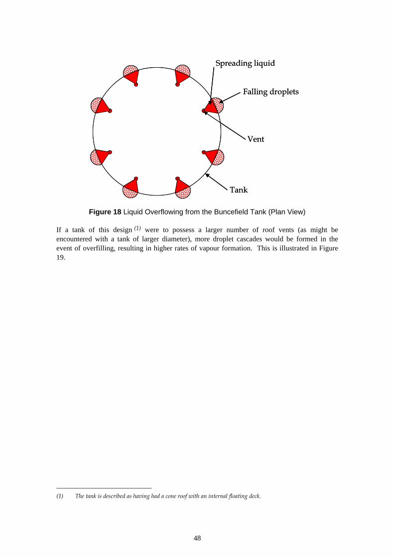
Vent
Spreading liquid
Falling droplets
Tank
Vent
Spreading liquid
Falling droplets
Tank
Figure 18 Liquid Overflowing from the Buncefield Tank (Plan View)
If a tank of this design (1) were to possess a larger number of roof vents (as might be encountered with a tank of larger diameter), more droplet cascades would be formed in the event of overfilling, resulting in higher rates of vapour formation. This is illustrated in Figure 19.
(1) The tank is described as having had a cone roof with an internal floating deck.
48

Figure 19 Liquid Overflowing from a Larger Diameter Tank (Plan View)
The presence of features on the outer surface of the tank (distributor plates, wind girders) seems to be an important factor in promoting the formation of free—falling liquid droplets. Such features cause liquid flowing down the side of the tank to detach from the surface of the wall.
It should be noted that petroleum storage tanks vary in design. Some tanks with a cone roof do not have a distributor plate running around the edge of the roof. The number and arrangement of vents within a cone roof may vary. Not all tanks with a floating deck have a roof.
The behaviour of liquid overflowing from a tank with a floating deck but no roof is harder to predict. Liquid would be expected to begin overflowing at a relatively low point in the tank wall. The liquid would flow down the tank wall until meeting an obstruction (such as a wind girder or an access platform) at which point it would be likely to detach from the wall and form a shower of droplets. This is displayed in Figure 20.
49
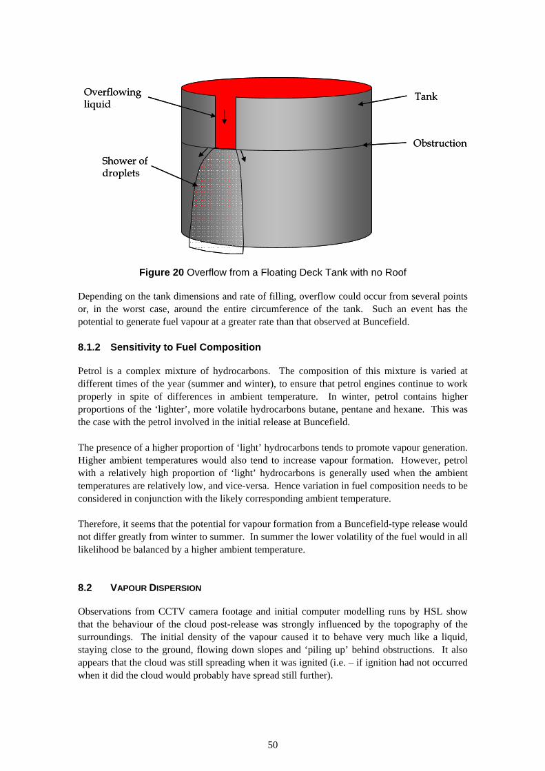
Tank
Obstruction
Overflowing liquid
Shower of droplets
Tank
Obstruction
Overflowingliquid
Shower of droplets
Figure 20 Overflow from a Floating Deck Tank with no Roof
Depending on the tank dimensions and rate of filling, overflow could occur from several points or, in the worst case, around the entire circumference of the tank. Such an event has the potential to generate fuel vapour at a greater rate than that observed at Buncefield.
8.1.2 Sensitivity to Fuel Composition
Petrol is a complex mixture of hydrocarbons. The composition of this mixture is varied at different times of the year (summer and winter), to ensure that petrol engines continue to work properly in spite of differences in ambient temperature. In winter, petrol contains higher proportions of the ‘lighter’, more volatile hydrocarbons butane, pentane and hexane. This was the case with the petrol involved in the initial release at Buncefield.
The presence of a higher proportion of ‘light’ hydrocarbons tends to promote vapour generation. Higher ambient temperatures would also tend to increase vapour formation. However, petrol with a relatively high proportion of ‘light’ hydrocarbons is generally used when the ambient temperatures are relatively low, and vice-versa. Hence variation in fuel composition needs to be considered in conjunction with the likely corresponding ambient temperature.
Therefore, it seems that the potential for vapour formation from a Buncefield-type release would not differ greatly from winter to summer. In summer the lower volatility of the fuel would in all likelihood be balanced by a higher ambient temperature.
8.2 VAPOUR DISPERSION
Observations from CCTV camera footage and initial computer modelling runs by HSL show that the behaviour of the cloud post-release was strongly influenced by the topography of the surroundings. The initial density of the vapour caused it to behave very much like a liquid, staying close to the ground, flowing down slopes and ‘piling up’ behind obstructions. It also appears that the cloud was still spreading when it was ignited (i.e. – if ignition had not occurred when it did the cloud would probably have spread still further).
50

Sophisticated computerised fluid dynamics (CFD) software is required to model this sort of behaviour. Simpler gas dispersion models assume that the cloud moves over flat, unobstructed terrain. In addition, most simple models will not work for very low wind speed conditions. The work currently underway at HSL uses CFD models.
The relative significance of different factors is discussed qualitatively below. It has not been possible to quantify the influence of these factors in the time available. This would require significant effort, performing multiple CFD model runs to test the effect of different inputs.
8.2.1 Release Duration
According to the MIIB initial report (MIIB, 2006d), the release of fuel continued unchecked for around 40 minutes before the explosion occurred. The extent and quantity of flammable vapour within the cloud increased throughout this period. It is likely that a release of shorter duration would have resulted in a smaller cloud in terms of the distances reached and the amount of fuel contained.
8.2.2 Topography
One of the most important factors influencing dispersion for a release of this type appears to be the topography of the surroundings (the presence of slopes and obstacles). A dense cloud moving over terrain that was more level and less obstructed than at Buncefield would be expected to spread further and more rapidly, but would not be as deep.
8.2.3 Weather
Weather (in terms of atmospheric stability and wind speed) is another significant factor. The calm, low wind speed conditions prevailing at the time of the Buncefield incident allowed a large vapour cloud to develop. Higher wind speeds or less stable weather would enhance dilution and dispersion of vapour, thereby reducing the extent of the flammable portion of the cloud.
8.2.4 Presence of Ignition Sources
As noted above, it appears from the information currently available that the cloud was still spreading when ignition occurred. Had ignition occurred at a later time, the cloud would have been correspondingly larger, potentially resulting in a larger explosion.
8.2.5 Source Term
A higher rate of vapour generation (for any of the reasons discussed in Section 8.1) would result in the cloud reaching a given extent more rapidly, and could ultimately lead to a larger cloud.
51
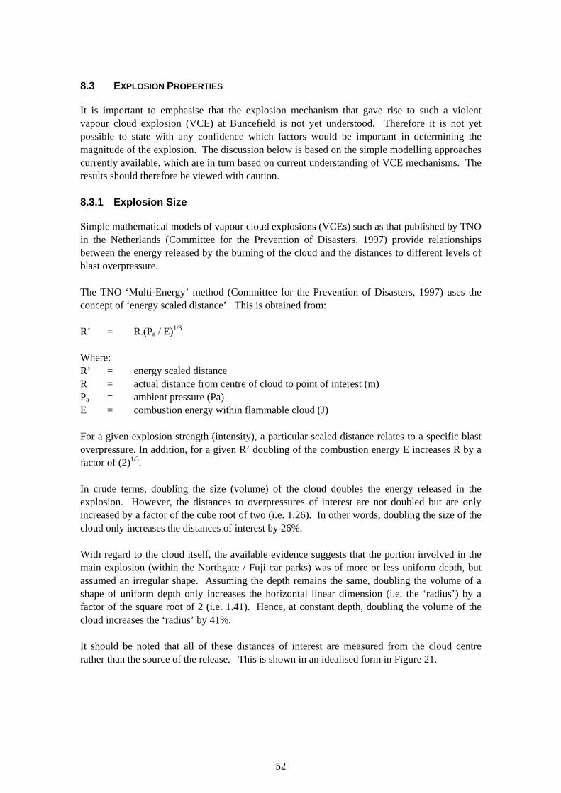
8.3 EXPLOSION PROPERTIES
It is important to emphasise that the explosion mechanism that gave rise to such a violent vapour cloud explosion (VCE) at Buncefield is not yet understood. Therefore it is not yet possible to state with any confidence which factors would be important in determining the magnitude of the explosion. The discussion below is based on the simple modelling approaches currently available, which are in turn based on current understanding of VCE mechanisms. The results should therefore be viewed with caution.
8.3.1 Explosion Size
Simple mathematical models of vapour cloud explosions (VCEs) such as that published by TNO in the Netherlands (Committee for the Prevention of Disasters, 1997) provide relationships between the energy released by the burning of the cloud and the distances to different levels of blast overpressure.
The TNO ‘Multi-Energy’ method (Committee for the Prevention of Disasters, 1997) uses the concept of ‘energy scaled distance’. This is obtained from:
R’ = R.(Pa / E)1/3
Where: R’ = energy scaled distance R = actual distance from centre of cloud to point of interest (m) Pa = ambient pressure (Pa) E = combustion energy within flammable cloud (J)
For a given explosion strength (intensity), a particular scaled distance relates to a specific blast overpressure. In addition, for a given R’ doubling of the combustion energy E increases R by a factor of (2)1/3.
In crude terms, doubling the size (volume) of the cloud doubles the energy released in the explosion. However, the distances to overpressures of interest are not doubled but are only increased by a factor of the cube root of two (i.e. 1.26). In other words, doubling the size of the cloud only increases the distances of interest by 26%.
With regard to the cloud itself, the available evidence suggests that the portion involved in the main explosion (within the Northgate / Fuji car parks) was of more or less uniform depth, but assumed an irregular shape. Assuming the depth remains the same, doubling the volume of a shape of uniform depth only increases the horizontal linear dimension (i.e. the ‘radius’) by a factor of the square root of 2 (i.e. 1.41). Hence, at constant depth, doubling the volume of the cloud increases the ‘radius’ by 41%.
It should be noted that all of these distances of interest are measured from the cloud centre rather than the source of the release. This is shown in an idealised form in Figure 21.
52

Cloud ‘radius’
Explosion radii
Source
Cloud centroid
Cloud ‘radius’
Explosion radii
Source
Cloud centroid
Figure 21 Measurement of Distances of Interest
The effect of doubling or trebling the size of the cloud on the proposed zone boundaries is illustrated in Table 9. It should be noted that an increase in cloud size of this magnitude would require some combination of the following factors:
• a significant increase in the rate of generation of vapour (arising, for example, from overfill of a larger tank, generating more or larger cascades of liquid droplets);
• a prolonged release duration (similar to or greater than that experienced at Buncefield); • delayed ignition of the cloud, at a point further from the release (allowing a bigger
cloud to develop prior to the explosion); and, • the same calm, low wind speed weather conditions.
53
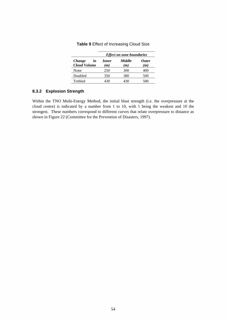
Table 9 Effect of Increasing Cloud Size
Effect on zone boundaries Change in Inner Middle Outer Cloud Volume (m) (m) (m) None 250 300 400 Doubled 350 380 500 Trebled 430 430 580
8.3.2 Explosion Strength
Within the TNO Multi-Energy Method, the initial blast strength (i.e. the overpressure at the cloud centre) is indicated by a number from 1 to 10, with 1 being the weakest and 10 the strongest. These numbers correspond to different curves that relate overpressure to distance as shown in Figure 22 (Committee for the Prevention of Disasters, 1997).
54

Figure 22 Multi Energy Method Blast Chart
The third progress report indicates that the overpressure in the centre of the explosion was of the order of 700 – 1000 mbar, which corresponds approximately to an initial strength of 7.
From Figure 22, it can be seen that the curves for strengths of 6 or above converge as the distance from the source is increased (i.e. at lower overpressures). For these explosion strengths, this means that increasing the strength of an explosion increases the distance associated with higher overpressures but has little or no effect on the distances to lower overpressures.
55

For example, increasing the initial strength of an explosion from 7 to 8 increases the distance to 700 mbar by around 12%, and the distance to 600 mbar by approximately 7%. However, the distance to 400 mbar would be virtually unchanged.
In the present case, an increase in explosion strength would be expected to produce a small increase (around 10% or less) in the inner zone distance, but virtually no change in the middle or outer zone distances.
8.4 SUMMARY
The influence of those factors judged to be of most significance is summarised in Table 10 and illustrated in Figure 23. Within Table 10, the various factors have been assigned a ‘high’, ‘medium’ or ‘low’ rating according to their influence on the LUP zone sizes.
Table 10 Importance of Influencing Factors
Factor Rating Comment SOURCE TERM Tank geometry
Fuel composition
DISPERSION
High
Low
Features of the tank design dictate the number and size of any liquid ‘showers’ formed. Winter fuel is more volatile than summer fuel, but ambient temperatures are lower. In summer the fuel is less volatile but ambient temperatures are higher.
Release duration High A longer release duration allows a bigger cloud to form. Topography High Features of the surroundings (slopes, barriers) have a marked
effect on behaviour of the dense vapour cloud. Weather High Calm, low wind speed conditions favour formation of a large
cloud. Ignition sources Medium The stage at which ignition of the cloud occurs (if at all) affects
the size of the resulting explosion. Ignition at a later time allows a bigger cloud to develop before the explosion.
EXPLOSION Cloud size Medium Doubling the volume of the cloud involved in the explosion
increases zone sizes, but by less than twice. Strength Low Given that the explosion is already relatively strong, a further
increase in strength produces a small increase in inner zone size and very little change in other zone sizes.
It is important to note that:
• several of these factors (tank geometry, time to ignition and topography) are strongly site-specific;
• it is conceivable that a combination of differences in these factors could lead to an explosion with more serious consequences than Buncefield;
• in the time available it has not been possible to quantify the impact of all of these factors on land-use planning zone boundaries; and,
56

• the reasons for the strength of the explosion at Buncefield are not yet understood, further investigation may indicate that there are additional factors that are important.
57

LARGER EXPLOSION Increased burn area. Increased overpressure distances.
LARGER DISTANCES Bigger zones.
MORE VIOLENT EXPLOSION Increased overpressure distances.
LARGER CLOUD More energy available to explosion.
MORE VAPOUR Tank geometry: more or larger showers of droplets.
WEATHER Calm, low wind speed conditions.
TIME TO IGNITE Longer delay prior to ignition.
TOPOGRAPHY Configuration of slopes and obstacles.
RELEASE DURATION Release continues for an extended period
LARGER EXPLOSIONIncreased burn area.Increased overpressuredistances.
LARGER DISTANCESBigger zones.
MORE VIOLENT EXPLOSIONIncreased overpressure distances.
LARGER CLOUDMore energy available to explosion.
MORE VAPOURTank geometry: more or largershowers of droplets.
WEATHERCalm, low wind speed conditions.
TIME TO IGNITELonger delay priorto ignition.
TOPOGRAPHYConfiguration of slopes and obstacles.
RELEASE DURATIONRelease continues for anextended period
Figure 23 Summary of Important Factors
58

9 SUMMARY AND CONCLUSIONS
Proposals have been developed for revised arrangements for HSE’s provision of LUP advice. The proposals have been developed by:
• reviewing published HSE research on the effects of explosions (Jeffries et al., 1997; Galbraith, 1998)
• considering the levels of damage to buildings observed around the Buncefield site; • considering the principles upon which HSE’s advice is based; and, • revisiting the justifications underlying the Sensitivity Level definitions for proposed
developments in the light of the first two activities.
Two options are presented:
• Option A: On the basis of blast damage observations at Buncefield, increase the size of the LUP zones only; or,
• Option B: Increase the size of the LUP zones and revise the development Sensitivity Levels.
Under the current system the Buncefield site has the inner, middle and outer zone boundaries set at distances of 120 m, 135 m and 185 m respectively. The proposed system would increase these distances to 250 m, 300 m and 400 m respectively.
The proposed changes to the Sensitivity Levels under Option B would place greater restrictions on the types of development that HSE would not advise against in the inner zone.
It is recommended that the proposed arrangements are applied to those sites which are similar to Buncefield in a number of important respects. These similarities would indicate that on the basis of what is known at present, the site has the potential to give rise to a VCE.
If implemented, it is recommended that the proposed arrangements are applied to sites with the following characteristics:
• the site is classed as either ‘upper tier’ or ‘lower tier’ under the Control of major Accident Hazards Regulations 1999 (the COMAH Regulations);
• the site stores petroleum in vertical, cylindrical, non-refrigerated above-ground storage tanks with side walls greater than 5 m in height; and,
• the filling rate of the storage tanks is greater than 100 m3 / hour.
These criteria align with those used by the Buncefield Standards Task Group, a joint COMAH Competent Authority and Industry committee (HSE, 2006).
In comparison with the current system, the proposed changes will, if implemented, result in:
• significantly larger zone boundaries for the sites affected (for both Options A and B);
59

• as a result of the increased area within the zones, a larger number of consultations concerning proposed developments in the vicinity of affected sites (for both Options A and B); and,
• more restrictive advice concerning developments in the inner zone (for Option B).
Furthermore, it is recognised that there may be significant implications in the proposed system for other types of site where a protection based approach is applied. These sites include bulk LPG (liquefied petroleum gas) storage, gasholders, other flammable liquid storage and other facilities presenting a hazard with an associated significant likelihood of death in the inner zone (including VCEs and other hazards such as fireballs). A review of the implications of the study findings for LUP arrangements applicable to other types of site is recommended.
An investigation of the sensitivity of the size of the proposed LUP zone boundaries to various factors was undertaken. The factors considered included:
• the rate at which vapour is formed and the conditions under which this occurs (the source term);
• the way in which the cloud moves (the dispersion of the vapour); • the quantity of fuel involved in the explosion (the explosion size); and, • the violence of the explosion (the explosion strength).
The factors considered to have the greatest influence on the size of the zones were:
• the geometry of the storage tanks at the site (this affects the way the liquid contents behave in the event of a tank being overfilled);
• the duration of a release (this affects the size of the flammable vapour cloud formed); • the topography of the tank surroundings (features in the surroundings such as slopes and
obstacles have a marked effect on the behaviour of the vapour cloud); and, • the weather conditions at the time that a release occurs (calm, low wind speed
conditions favour formation of a large cloud).
60

10 REFERENCES
Advisory Committee on Major Hazards, 1984. Third Report – The control of major hazards. HMSO.
Carter, D A, 1995. The Scaled Risk Integral – A Simple Numerical Representation of Case Societal Risk for Land Use Planning in the Vicinity of Major Accident Hazards. In Loss Prevention and Safety Promotion in the Process Industries, Volume II. Eds. Mewis J J, Pasman H J and De Rademaeker, E E. Elsevier Science.
Committee for the Prevention of Disasters, 1997. Methods for the Calculation of Physical Effects, Part 2. CPR 14E (the Yellow Book).
DETR, 2000. Hazardous substances consent - A guide for industry. HMSO. Available at: http://www.communities.gov.uk/index.asp?id=1143296 .
Galbraith K Lt Col, 1998. Review of blast injury data and models. HSE Books, CRR 192/1998. Available at: http://www.hse.gov.uk/research/crr_pdf/1998/CRR98192.pdf .
HSE, (-). PADHI - HSE's Land Use Planning Methodology. Available at: http://www.hse.gov.uk/landuseplanning/padhi.pdf .
HSE, 1989. Risk criteria for land-use planning in the vicinity of major industrial hazards. HMSO.
HSE, 1996. The Pipeline Safety Regulations 1996. HSE Books L82.
HSE, 2001. Reducing risks, protecting people. HSE Books C/100.
HSE, 2006. Buncefield Standards Task Group Initial report – recommendations requiring immediate action. Available at: http://www.hse.gov.uk/comah/buncefield/bstg1.htm .
Jeffries R M et al., 1997. Derivation of fatality probability functions for occupants of buildings subject to blast loads - Phase 4. HSE Books, CRR 151/1997. Available at: http://www.hse.gov.uk/research/crr_pdf/1997/CRR97151.pdf .
MIIB, 2006a. The Buncefield Investigation - Progress Report. Available at: http://www.buncefieldinvestigation.gov.uk/reports/index.htm .
MIIB, 2006b. The Buncefield Investigation – Second Progress Report. Available at: http://www.buncefieldinvestigation.gov.uk/reports/index.htm .
MIIB, 2006c. The Buncefield Investigation - Third Progress Report. Available at: http://www.buncefieldinvestigation.gov.uk/reports/index.htm .
MIIB, 2006d. Buncefield Major Incident Investigation - Initial report to the Health and Safety Commission and the Environment Agency of the investigation into the explosions and fire at the Buncefield oil storage and transfer depot, Hemel Hempstead, on 11 December 2005. Available at: http://www.buncefieldinvestigation.gov.uk/reports/index.htm .
61
APPENDIX 1 REVIEW OF RESEARCH ON EXPLOSION EFFECTS
A review of HSE research reports dealing with the effects of blast on building occupants was performed (Jeffries et al., 1997; Galbraith, 1998), to assist in understanding the impact of a VCE on people at different types of development.
Research on Fatality Probabilities for Building Occupants Subject to Blast (Jeffries et al., 1997)
The research culminating in the HSE research report CRR 151/1997 (Jeffries et al., 1997) sought to develop a model for prediction of the likelihood of fatality for building occupants exposed to a vapour cloud explosion. The model was developed by W S Atkins from first principles. It considered the effect of a blast wave on different components of a building structure (glazing, cladding and supporting frame), together with the effects of these failures on the occupants (impact by glass fragments, impact by cladding debris and the effect of structural collapse).
The model was applied to a number of different structure types and the results presented as a series of fatality probability curves.
The authors highlighted a feature of the model that makes comparison of the relative safety of different buildings difficult. This feature is the sensitivity of the predicted fatality probabilities to the assumed internal layout of the building.
The model assumes that, for example, glazing fragments will affect those directly behind the breaking window, with the fatality probability decreasing as the fragments travel into the building (see Figure 24).
62

90% Probability
50% Probability
10% Probability
1% Probability
Fatality Probability Zones
PLAN VIEW
Wall
Window
BUILDING INTERIOR
90% Probability
50% Probability
10% Probability
1% Probability
Fatality Probability Zones
PLAN VIEW
Wall
Window
BUILDING INTERIOR
Figure 24 Pattern of Fatality Probability from Glazing Fragments
The total fatality probability (Pt) is then derived from a weighted sum of the plan areas associated with ‘zones’ of different fatality probability, divided by the overall plan area of the building:
Pt = Σ Zone area x Probability associated with zone Total area
The sensitivity of the model arises from the assumption that internal walls are unaffected in the event of an explosion and effectively shield areas behind them from glass fragments and debris. Hence areas within a building with no external walls (such as hallways, corridors and internal rooms) ‘dilute’ the overall fatality probability.
This effect can be particularly significant with some steel or concrete framed buildings that have a central ‘core’ housing lifts, stair wells or amenities. Since building occupants tend to spend a small proportion of the time in such internal spaces, the overall impact of the assumption is to reduce the predicted fatality probability for certain buildings and cause some anomalies when different building types are compared.
In addition, the authors make the following statement in relation to the prediction of fatality probabilities:
63
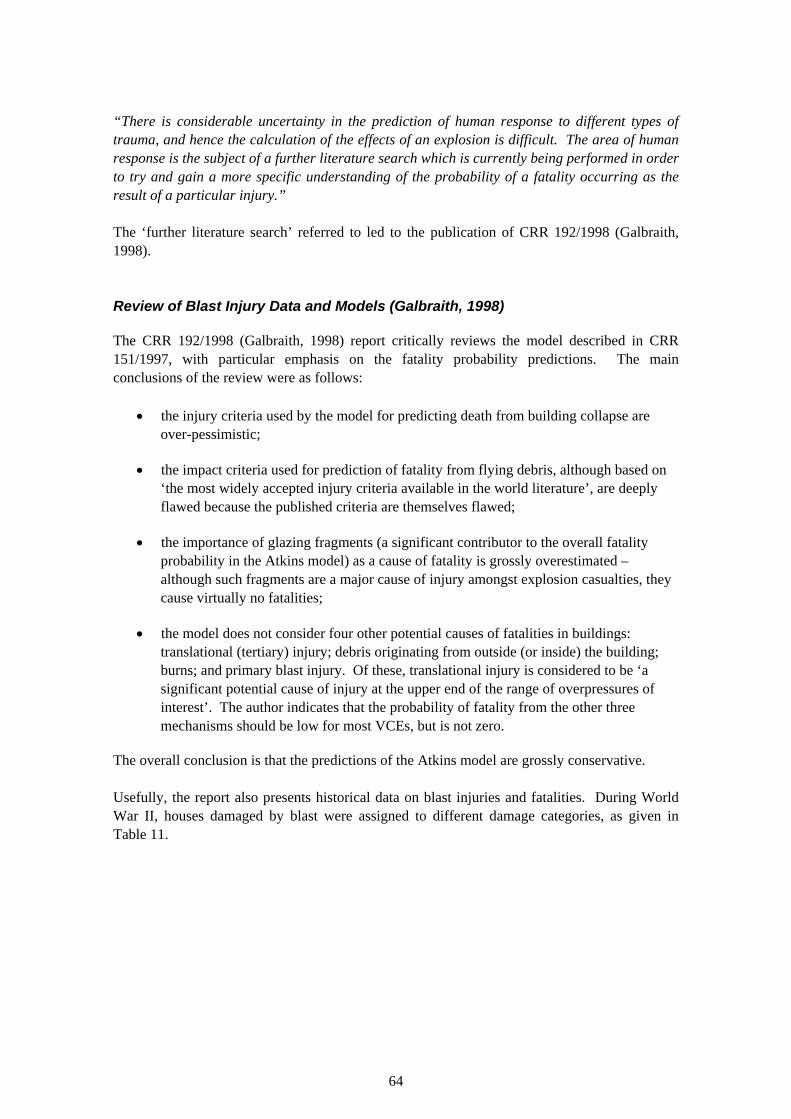
“There is considerable uncertainty in the prediction of human response to different types of trauma, and hence the calculation of the effects of an explosion is difficult. The area of human response is the subject of a further literature search which is currently being performed in order to try and gain a more specific understanding of the probability of a fatality occurring as the result of a particular injury.”
The ‘further literature search’ referred to led to the publication of CRR 192/1998 (Galbraith, 1998).
Review of Blast Injury Data and Models (Galbraith, 1998)
The CRR 192/1998 (Galbraith, 1998) report critically reviews the model described in CRR 151/1997, with particular emphasis on the fatality probability predictions. The main conclusions of the review were as follows:
• the injury criteria used by the model for predicting death from building collapse are over-pessimistic;
• the impact criteria used for prediction of fatality from flying debris, although based on ‘the most widely accepted injury criteria available in the world literature’, are deeply flawed because the published criteria are themselves flawed;
• the importance of glazing fragments (a significant contributor to the overall fatality probability in the Atkins model) as a cause of fatality is grossly overestimated – although such fragments are a major cause of injury amongst explosion casualties, they cause virtually no fatalities;
• the model does not consider four other potential causes of fatalities in buildings: translational (tertiary) injury; debris originating from outside (or inside) the building; burns; and primary blast injury. Of these, translational injury is considered to be ‘a significant potential cause of injury at the upper end of the range of overpressures of interest’. The author indicates that the probability of fatality from the other three mechanisms should be low for most VCEs, but is not zero.
The overall conclusion is that the predictions of the Atkins model are grossly conservative.
Usefully, the report also presents historical data on blast injuries and fatalities. During World War II, houses damaged by blast were assigned to different damage categories, as given in Table 11.
64

Table 11 WWII Housing Damage Categories
Category Description A Houses completely demolished – i.e., with over 75% of external brickwork
demolished. B Houses so badly damaged that they are beyond repair and must be
demolished. Property included in this category if 50-75% external brickwork is destroyed, or in the case of less severe destruction, the remaining walls have gaping cracks rendering them unsafe.
Cb Houses rendered uninhabitable by serious damage, needing repairs so extensive that they must be postponed until after the war, e.g. – partial or total collapse of roof structure; partial demolition of 1 or 2 external walls up to 25% of the whole; severe damage to load bearing partitions necessitating demolition and replacement.
Ca Houses rendered uninhabitable, but reasonably quickly repairable under war-time conditions; damage sustained not to exceed minor structural damage, and partitions and joinery wrenched from fixings.
D Houses requiring repairs to remedy serious inconveniences, but remaining habitable, e.g. – damage to ceilings and tiling; battens and roof covering; minor fragmentation effects on walls; broken window glass. NB – cases with <10% windows broken were not included in this category.
The report also presents data on the causes of injury in air raid victims. The data for people in dwellings are presented in Table 12, with the contribution from bomb fragments (pieces of weapon casing) removed.
Table 12 Causes of Injuries in Air Raid Victims in Dwellings (excluding bomb fragments)
% Contribution from Cause
Blast Glass
Other Flying Debris
Falling Debris Fall Burns Other Unknown
Fatal 2.8 0.2 19.0 53.7 6.8 3.1 2.1 12.2 Hospital 0.2 11.1 20.5 47.7 12.3 1.3 6.1 0.8
Note that:
• the contributions from blast (primary effects) and burns are small; • the contribution from glass to fatalities is very small (1 person in 353, or 1 person in
303 excluding bomb fragment casualties), although this mechanism contributes significantly to injuries;
• the most significant contributions are from other flying debris and falling debris (the latter presumably associated with structural collapse, whether partial or total);
• the small but significant contribution from falls may be associated with tertiary effects; and,
65

• these data relate to air raids, where some warning may have been given – data for V2 explosions (not presented in the report), where there was no warning, are said to show a lower contribution from falling debris, with an increased proportion from flying debris.
Data are also presented which relate the building damage category (see Table 11) to the number of fatalities for V1 bomb explosions. This information is reproduced in Table 13.
66
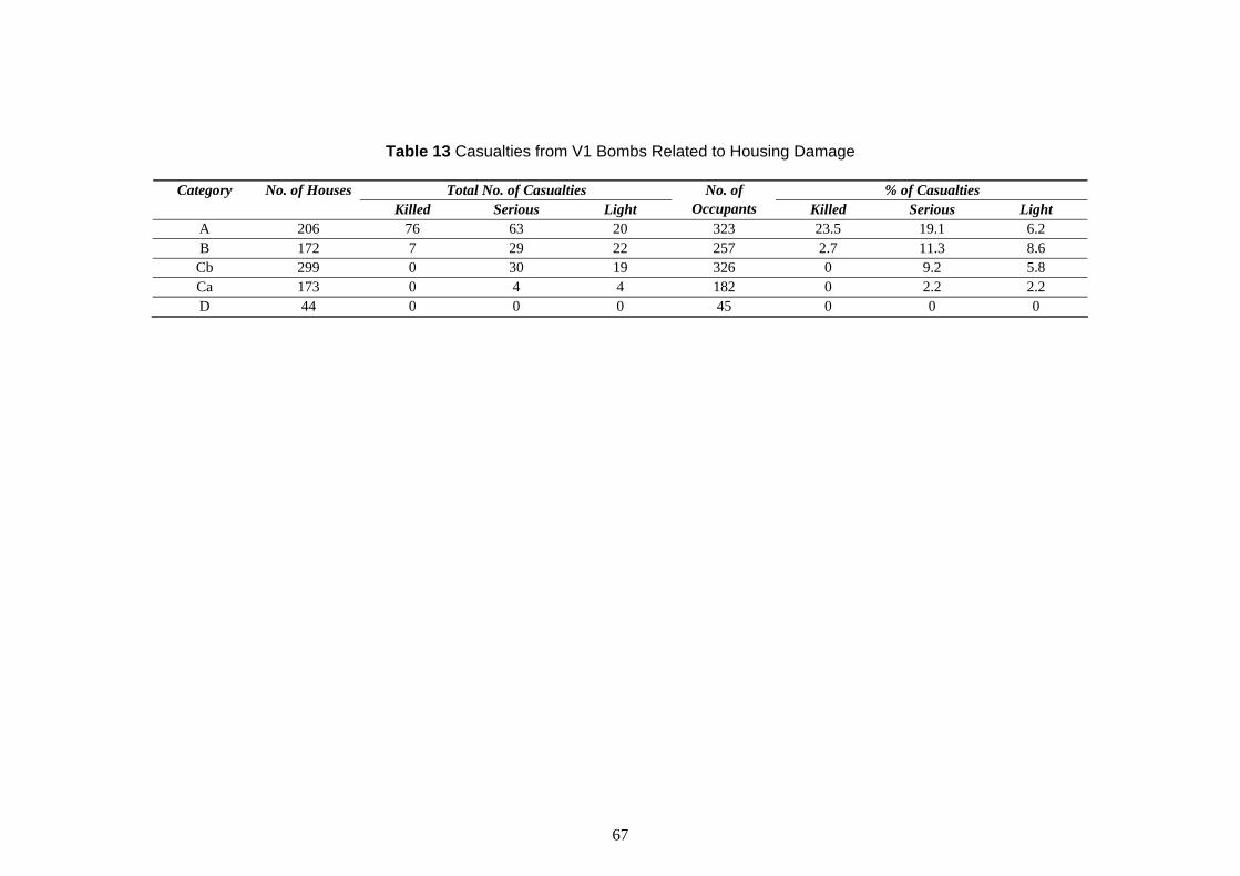
Table 13 Casualties from V1 Bombs Related to Housing Damage
Category No. of Houses Total No. of Casualties No. of % of Casualties Killed Serious Light Occupants Killed Serious Light
A 206 76 63 20 323 23.5 19.1 6.2 B 172 7 29 22 257 2.7 11.3 8.6
Cb 299 0 30 19 326 0 9.2 5.8 Ca 173 0 4 4 182 0 2.2 2.2 D 44 0 0 0 45 0 0 0
67
With regard to the data in Table 13 the following observations are made:
• fatalities are found principally in houses with A damage, with a few in category B but none at all in the C and D categories; and,
• in category A damaged houses, over half of the occupants were not even lightly injured.
Estimates of the overpressure required to cause category A damage range from 20 psi (1.4 bar) for a short duration blast from 1 ton of TNT, to 12 psi (0.83 bar, 830 mbar) for a slow rising pressure wave, taking about 100 ms to reach its peak. This latter case is more akin to a VCE. Note also that, according to current understanding, for a VCE in a region of ‘typical’ congestion, an overpressure of this magnitude would occur within the burning cloud or close to the cloud edge. Hence the contribution from burn injuries in a Category A damaged building will be more significant for a VCE event than for a condensed phase explosion. Burn injury may arise either from direct contact with the burning cloud (if burning vapour enters when, for example, windows are broken by the pressure wave) or from secondary fires started in the building by the VCE. Escape from a secondary fire in a building that is significantly blast-damaged may be hindered by debris and / or injury.
68

APPENDIX 2 BUILDING DAMAGE OBSERVATIONS
A summary of the damage to buildings around the Buncefield site has been prepared by studying photographic and video evidence collected as part of the HSE investigation. A map showing building locations is displayed in Figure 25. The map also indicates the approximate extent of the flammable cloud as indicated by burned material (presented in the first progress report (MIIB, 2006a)) and the possible cloud extent in those regions where the position is less certain. The damage information is presented in Table 14.
69
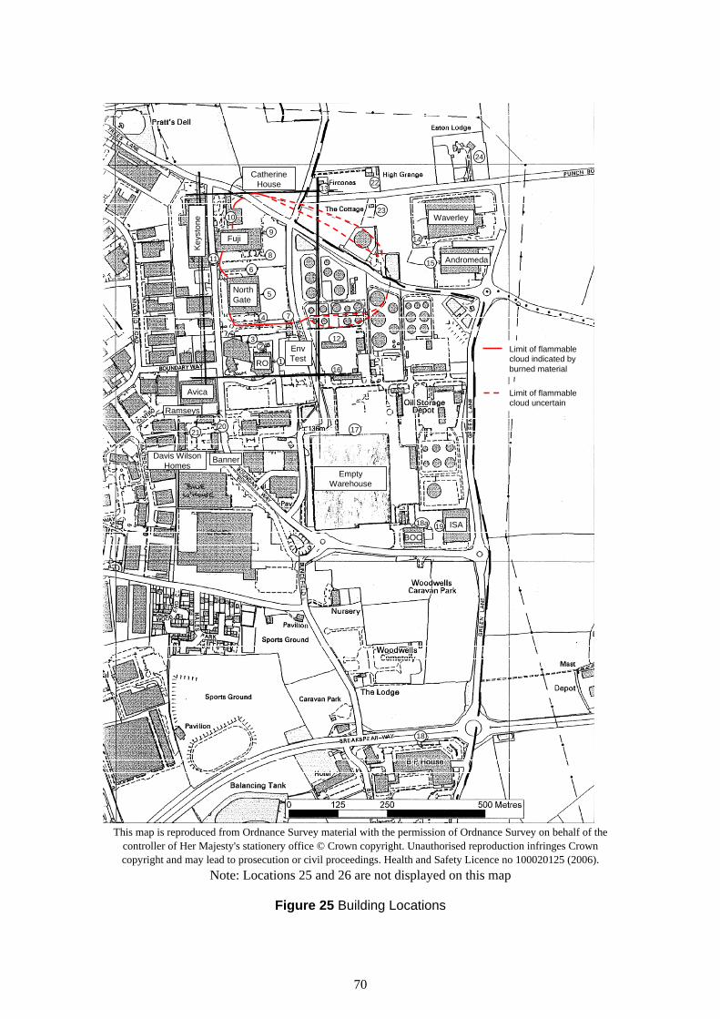
Fuji
NorthGate
CatherineHouse
Waverley
Andromeda
RO
EnvTest
Keys
tone
Avica
EmptyWarehouse
ISABOC
Ramseys
BannerDavis WilsonHomes
1
23
4
5
8
9
1322
23
14
15
12
16
172021
11
24
18a 19
18
Limit of flammable cloud indicated by burned material
Limit of flammable cloud uncertain
6
7
10
24
Fuji
4
5
8
9
13 22
23
11 6
7
10
North Gate
Catherine House
Keys
tone
lWaver ey
15 Andromeda
14
RO
Avi
1
2 3
Env Test
ca
Ramseys
12 Limit of flammable cloud indicated by burned material
Limit of flammable cloud uncertain
16
20 1721
ISA BOC
il
19
Empty Warehouse
Banner Davis W son Homes
18a
18
This map is reproduced from Ordnance Survey material with the permission of Ordnance Survey on behalf of the controller of Her Majesty's stationery office © Crown copyright. Unauthorised reproduction infringes Crown copyright and may lead to prosecution or civil proceedings. Health and Safety Licence no 100020125 (2006).
Note: Locations 25 and 26 are not displayed on this map
Figure 25 Building Locations
70

Table 14 Building Damage
Ref. Building Damage Description 1 RO Developments – E side Broken windows (>90% of larger panes, >50% of smaller panes), frames distorted, some pushed in
completely. Interior – ceiling panels blown off, fallen light fittings. 2 RO Developments – N Virtually all windows broken and frames displaced on 1st, 2nd and 3rd floor. Frames remaining but distorted
side on ground floor. Some cracking of brick cladding around windows. Interior not clearly visible in photos. 3 RO Developments – brick- E face of corner – only a few windows broken, some frames distorted, slight cracking of brick cladding in
clad ‘annex’ with steel- places. Some distortion of steel cladding on vertical tubes attached to wall (presumed part of building clad sections either side heating or ventilation system). Roller-shutter door pushed in.
N face of corner – almost all windows broken and frames displaced. Cracking of brick cladding, some bricks visible on ground outside building.
3a RO Developments – steel- Some distortion of cladding and window breakage. clad section to E side of brick-clad ‘annex’
3b RO Developments – steel- Significant distortion of cladding and window breakage. Cladding visible on ground outside building. clad section to W side of brick-clad ‘annex’
4 Northgate Building - S All windows broken and frames completely displaced. Some brick cladding also removed, particularly on side ground floor and around stair well. Significant cracking of remaining brick cladding. Some displacement
of internals – light boxes and ceiling battens hanging down, furniture moved. Internal damage appears more significant on ground floor – fallen pipes & cables visible. (Note – on 1st and 2nd floor cladding is brick mounted in front of concrete panels. Where the brick has been removed, it appears to have fallen to the ground outside the building, leaving the concrete panels exposed)
5 Northgate Building – E All windows broken and frames displaced. Approximately 2/3 of brick cladding removed. Walls blackened side at the N end (the building caught fire following the incident). Roof collapsed into upper floor at NE corner.
Significant internal damage – tangled wreckage visible. There appears to have been partial collapse of the floor slab at one location between ground and 1st floor. Where brick has been removed, some cracking of the concrete panels is visible.
71

Ref. Building Damage Description 6 Northgate Building – N
side, near NE corner Damage similar to E side, NE corner. At one location, in addition to the brick cladding being removed, a concrete panel has also fallen down outside the building. An adjoining structure (loading bay) has been destroyed apart for some horizontal steel beams projecting from the main building.
7 Environmental Test House At N end, brick walls demolished and collapsed inwards, roof partly collapsed and steel roofing material torn off. Cracking of internal block-work walls visible. Louvres in W wall damaged (pushed in). Cladding at N end of W wall cracked and pushed in. At S end of W wall, door / louvres completely removed.
8 Fuji Building (S wall) Along the S edge, almost all cladding has been removed and pushed into the building in places. The outermost edge of the roof has collapsed. Internal damage appears significant where visible – tangled wreckage. Some of the outermost reinforced concrete vertical frame members have been bent / cracked.
9 Fuji Building (E wall) Along the E wall, all external cladding / windows have been removed (although it is not possible to tell from the photographs how many windows there were) and internal damage appears significant. The roof is partially collapsed.
10 Catherine House Building comprises multi-storey offices (long axis of building pointing N-S) with what appears to be a 2storey annex at the SE corner. Main part of building, E side – windows broken (almost all) and some distortion of cladding. At the SE corner of the main building, the structure appears to have undergone partial collapse. Annex – significant glass breakage and distortion of cladding, with more extensive damage at SE corner.
11 Keystone Distribution SE corner - some cracking of exterior concrete wall and distortion of small louvred panels. 12
13
14
Loading gantry
Fircones (single storey brick-built house)
Waverley (warehouse to E of site)
Distortion / displacement of some corrugated steel roof panels and side cladding. No damage to steel frame or process pipework. Roof tiles displaced, battens exposed in places, close to ridge of roof. Windows boarded in photo – presumably broken. Chimney stack cracked but still upright. Some cracking of walls. External structure (car port) partly demolished. Much of cladding along W wall removed. Along S wall, some distortion of cladding, a few panels removed.
15 Andromeda (warehouse to E of site)
Significant distortion of cladding, pushed in in places (especially at NW corner) around 25% removed. Some distortion of frame at NW corner also. Some (slight) displacement of stacked goods inside warehouse. Apparently no window breakage on glazed annex to S of building, but cladding removed on main warehouse structure.
16 Control Building Most windows broken on N side. Video footage shows some internal damage (mostly collapsed ceilings).
72

Ref. Building Damage Description 17 Empty warehouse to
site S of N side – steel clad walls pushed inwards with some removal of cladding. Bowing of roof in middle of each
‘bay’. Horizontal bars to which cladding attached torn away from vertical members of frame. Some distortion of steel vertical frame members.
18 BP House A few windows broken and some damage to facia under eaves (blown in / off). 18a 19 20
21
BOC ISA Avica / Ramseys / Banner
Davis Wilson Homes
N Side – Steel cladding dislodged and collapsed outwards. Some displacement of goods on racking inside. W Side – roller shutter doors pushed in. N side - some cladding partly removed and blow in. Ramseys, E side – approx 20% window breakage and damage to facia on 1st floor. Banner, E side – some displacement of roof tiles, damage to facia under eaves, little window breakage. Brick cladding appears undamaged. Avica, E side – steel cladding torn off and collapsed outwards. Cracking of brick cladding on lower part of wall. Few windows in this side, but about 50% broken. Avica, N side – more windows in this side, 50-75% broken. Some brick cladding removed at NE corner, cracked in other places. Displacement of some roof tiles (around 20%). A few (<10%) windows broken. Damage to facia under eaves.
22 High Grange (2 storey brick house)
Approx. 50% of roof tiles displaced. Most windows broken, chimney stack cracked.
23 The Cottage (single storey brick house)
Roof almost completely collapsed, windows broken. One gable end wall and chimney collapsed inwards, cracking of remaining walls.
24 Eaton Lodge (single storey house)
Most windows broken, some roof tiles displaced. Lean-to garage roof fallen in.
25 Leverstock Green School (approx 1.5 km to SSW)
Some glass breakage (<20% overall)
26 Houses & Flats (approx 1.3 km to SSW)
Some breakage of larger glass panes, approx 10-20%
73
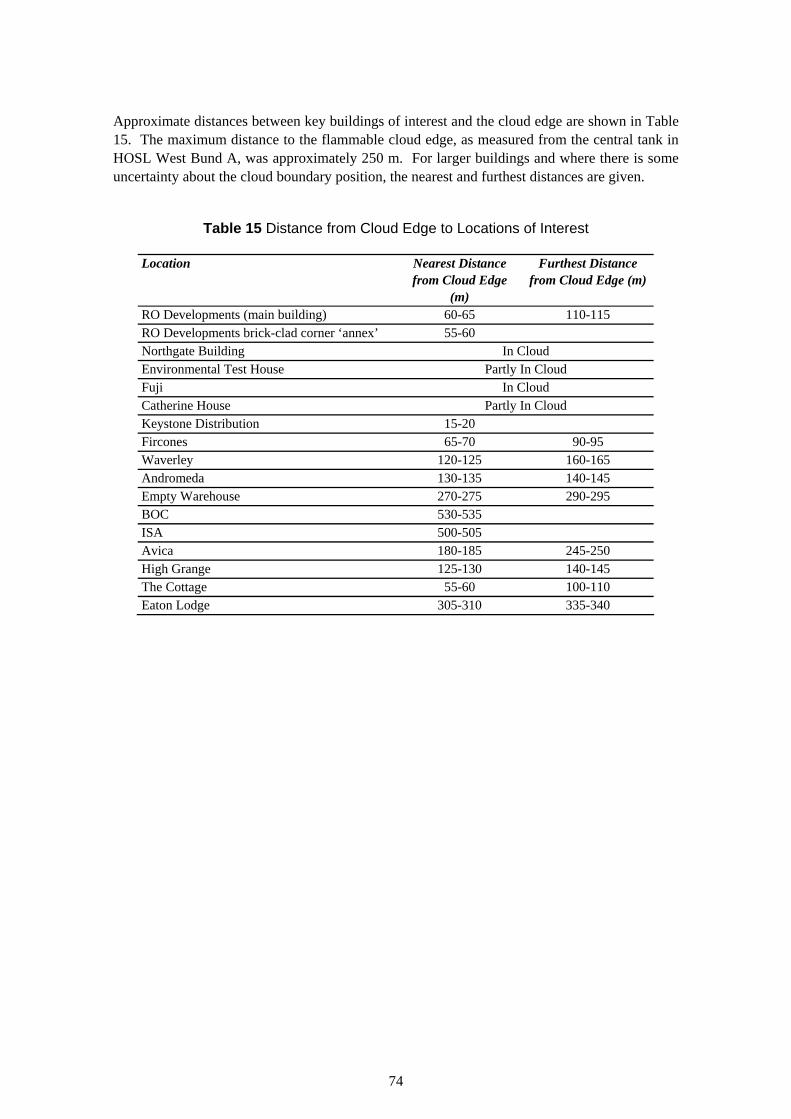
Approximate distances between key buildings of interest and the cloud edge are shown in Table 15. The maximum distance to the flammable cloud edge, as measured from the central tank in HOSL West Bund A, was approximately 250 m. For larger buildings and where there is some uncertainty about the cloud boundary position, the nearest and furthest distances are given.
Table 15 Distance from Cloud Edge to Locations of Interest
Location Nearest Distance Furthest Distance from Cloud Edge from Cloud Edge (m)
(m) RO Developments (main building) 60-65 110-115 RO Developments brick-clad corner ‘annex’ 55-60 Northgate Building In Cloud Environmental Test House Partly In Cloud Fuji In Cloud Catherine House Partly In Cloud Keystone Distribution 15-20 Fircones 65-70 90-95 Waverley 120-125 160-165 Andromeda 130-135 140-145 Empty Warehouse 270-275 290-295 BOC 530-535 ISA 500-505 Avica 180-185 245-250 High Grange 125-130 140-145 The Cottage 55-60 100-110 Eaton Lodge 305-310 335-340
74

APPENDIX 3 ESTABLISHING REVISED ZONE BOUNDARIES
When using a ‘protection’ (i.e. consequence) based approach, the locations of the LUP zone boundaries are normally set as follows:
• inner zone: significant likelihood of death from the selected event; • middle zone: dangerous dose to a typical population from the selected event; and, • outer zone: dangerous dose to a sensitive / vulnerable population from the selected
event.
Inspection of Table 11and Table 13 indicates that:
• building damage similar to Category A corresponds to a likelihood of fatality that is significantly above a dangerous dose, particularly when taking into account the observation in Appendix 1, that the contribution from burns may be increased for a VCE relative to a condensed phase explosion; and,
• building damage similar to Category B corresponds to a likelihood of fatality (<3%) that is close to that for a dangerous dose.
It is more difficult to identify any correspondence between building damage and a dangerous dose to a sensitive / vulnerable population. None of the information reviewed to date has contained data on the vulnerability of particular groups (such as children or the elderly) to explosion effects. It is postulated that the combination of the shock of being exposed to an explosion, together with injury from glass or other debris, could result in fatalities among particularly susceptible individuals. In the absence of other information, this is taken to correspond to Category Cb damage.
There are also difficulties associated with assigning the observed damage in Appendix 2 to one of the categories in Table 11. The damage categories relate to housing, whereas the observed damage relates to a variety of building types. Building construction can have a significant effect on response to blast. A level of blast overpressure causing collapse of a house may result in severe damage to the glazing and cladding of a steel- or concrete-framed structure, but not complete collapse of the supporting frame.
Therefore, rather than attempt to assign observed damage to one of the damage categories, the information in Table 13 has been used to form a judgement as to the potential harm to occupants that could have arisen from the damage observed. The levels of harm assigned reflect those anticipated in the different LUP zones, as listed above. Hence the ‘high’, ‘medium’ and ‘low’ categories relate to the inner, middle and outer zones respectively. The ‘minimal’ category relates to the region beyond the outer zone. In doing this, it has been borne in mind that typical masonry-built houses tend to be more susceptible to collapse than steel- or concrete-framed structures. The results are summarised in Table 16.
75
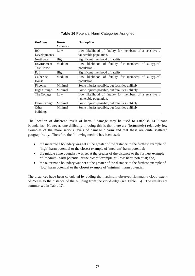
Table 16 Potential Harm Categories Assigned
Building Harm Description Category
RO Low Low likelihood of fatality for members of a sensitive / Developments vulnerable population. Northgate High Significant likelihood of fatality. Environment Medium Low likelihood of fatality for members of a typical Test House population. Fuji High Significant likelihood of fatality. Catherine Medium Low likelihood of fatality for members of a typical House population. Fircones Minimal Some injuries possible, but fatalities unlikely. High Grange Minimal Some injuries possible, but fatalities unlikely. The Cottage Low Low likelihood of fatality for members of a sensitive /
vulnerable population. Eaton Grange Minimal Some injuries possible, but fatalities unlikely. Other Minimal Some injuries possible, but fatalities unlikely. buildings
The location of different levels of harm / damage may be used to establish LUP zone boundaries. However, one difficulty in doing this is that there are (fortunately) relatively few examples of the more serious levels of damage / harm and that these are quite scattered geographically. Therefore the following method has been used:
• the inner zone boundary was set at the greater of the distance to the furthest example of ‘high’ harm potential or the closest example of ‘medium’ harm potential;
• the middle zone boundary was set at the greater of the distance to the furthest example of ‘medium’ harm potential or the closest example of ‘low’ harm potential; and,
• the outer zone boundary was set at the greater of the distance to the furthest example of ‘low’ harm potential or the closest example of ‘minimal’ harm potential.
The distances have been calculated by adding the maximum observed flammable cloud extent of 250 m to the distance of the building from the cloud edge (see Table 15). The results are summarised in Table 17.
76
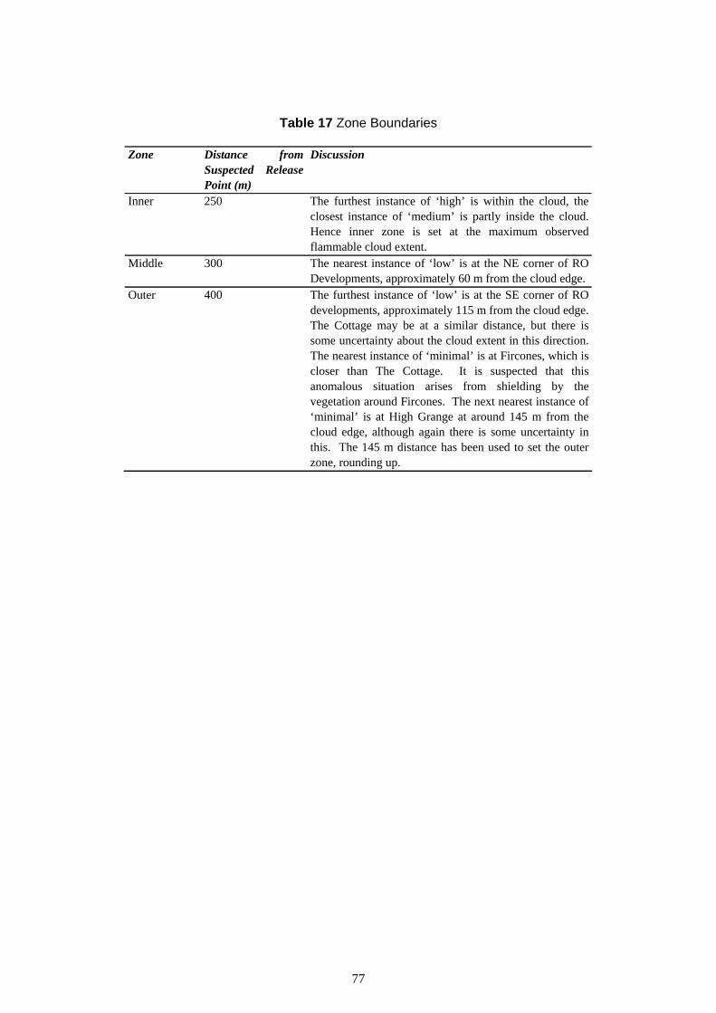
Table 17 Zone Boundaries
Zone Distance from Discussion SuspectedPoint (m)
Release
Inner 250 The furthest instance of ‘high’ is within the cloud, the closest instance of ‘medium’ is partly inside the cloud. Hence inner zone is set at the maximum observed flammable cloud extent.
Middle 300 The nearest instance of ‘low’ is at the NE corner of RO Developments, approximately 60 m from the cloud edge.
Outer 400 The furthest instance of ‘low’ is at the SE corner of RO developments, approximately 115 m from the cloud edge. The Cottage may be at a similar distance, but there is some uncertainty about the cloud extent in this direction. The nearest instance of ‘minimal’ is at Fircones, which is closer than The Cottage. It is suspected that this anomalous situation arises from shielding by the vegetation around Fircones. The next nearest instance of ‘minimal’ is at High Grange at around 145 m from the cloud edge, although again there is some uncertainty in this. The 145 m distance has been used to set the outer zone, rounding up.
77

APPENDIX 4 CASE SOCIETAL CONCERNS - WORKPLACES
The discussion in Section 6.2.2 also has implications for the societal concerns associated with workplace type developments. That is, the case societal concerns associated with these developments may be greater for such populations when exposed to a VCE hazard than whenexposed to some other hazards (such as chlorine). The inability (or lack of opportunity) to carryout appropriate emergency action in the event of a VCE could leave larger numbers of peopleexposed to the hazard.
This increase in case societal concerns can be illustrated using the Scaled Risk Integral (SRI).Historically (i.e. prior to the introduction of PADHI), HSE has used the SRI to give anindication of the case societal concerns associated with a given development (Carter, 1995).The SRI is calculated using:
SRI = (P.R.T)/A
Where: P = population factor (see below) R = individual risk of dangerous dose at development (chances per million per year,
cpm) T = proportion of time for which the development is occupied A = area associated with development (ha)
The population factor P is obtained using:
P = ½ [mn + (mn)2]
Where: m = modifier reflecting population type (1 for house residents, 2 for a sensitive /
vulnerable population and 0.25 for people at a workplace) n = number of people occupying development
The case societal concerns were judged to be ‘significant’ if the SRI exceeded 2500, with a presumption in favour of advising against in such cases (although SRI was not the only factor considered when formulating advice).
The SRI result is quite sensitive to the value of the quantity (mn). The origin of the m value of 0.25 for a working population is not clear, but it is thought that a value of less than 1 represents a less sensitive or vulnerable population and reflects the justification stated in Table 3 (occupants fit, healthy and easily organised for emergency action).
It is proposed that if, as argued above, the opportunity for emergency action is limited for a VCE hazard, then a higher value of m would be more appropriate. This would reflect the increased vulnerability of the population to the effects of the hazard. The effect of varying m for a working population is illustrated in Table 18.
78
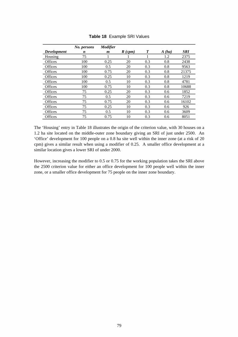
Table 18 Example SRI Values
No. persons Modifier Development n m R (cpm) T A (ha) SRI Housing 75 1 1 1 1.2 2375 Offices 100 0.25 20 0.3 0.8 2438 Offices 100 0.5 20 0.3 0.8 9563 Offices 100 0.75 20 0.3 0.8 21375 Offices 100 0.25 10 0.3 0.8 1219 Offices 100 0.5 10 0.3 0.8 4781 Offices 100 0.75 10 0.3 0.8 10688 Offices 75 0.25 20 0.3 0.6 1852 Offices 75 0.5 20 0.3 0.6 7219 Offices 75 0.75 20 0.3 0.6 16102 Offices 75 0.25 10 0.3 0.6 926 Offices 75 0.5 10 0.3 0.6 3609 Offices 75 0.75 10 0.3 0.6 8051
The ‘Housing’ entry in Table 18 illustrates the origin of the criterion value, with 30 houses on a 1.2 ha site located on the middle-outer zone boundary giving an SRI of just under 2500. An ‘Office’ development for 100 people on a 0.8 ha site well within the inner zone (at a risk of 20 cpm) gives a similar result when using a modifier of 0.25. A smaller office development at a similar location gives a lower SRI of under 2000.
However, increasing the modifier to 0.5 or 0.75 for the working population takes the SRI above the 2500 criterion value for either an office development for 100 people well within the inner zone, or a smaller office development for 75 people on the inner zone boundary.
79

Published by the Health and Safety Executive 02/07
Health and Safety Executive
Revised land use planning arrangements around large scale petroleum depots Following the incident at the Buncefield Oil Storage Depot in December 2005, the Health and Safety Executive (HSE) commissioned Environmental Resources Management (ERM) to assist in reviewing HSE’s approach to providing landuse planning (LUP) advice in the vicinity of similar installations.
Proposals for revised arrangements for provision of LUP advice have been developed. Two options are presented. The proposals are based on a review of information on the effect of blast on building occupants, observations of the blast damage at Buncefield, and a review of some of the justification underpinning certain aspects of the current arrangements. Both of the options proposed would result in greater restriction on development of land in the vicinity of those sites affected.
For both options, the proposed system would operate within a defined geographical area around affected sites. The sensitivity of the size of this area to certain factors has been investigated.
This report and the work it describes were funded by the Health and Safety Executive (HSE). Its contents, including any opinions and/or conclusions expressed, are those of the author alone and do not necessarily reflect HSE policy.
RR511
www.hse.gov.uk