· web viewall axometrics production machines are controlled entirely using the axometrics...
TRANSCRIPT

Axometrics, Inc.103 Quality Circle, Suite 215Huntsville, AL 35806Phone: (256) 704-3332Fax: (256) 971-2073
E-Mail: [email protected]: http://www.axometrics.com
Axometrics General Production and QC
Software
USER’S MANUAL
Software Version 4.0
©2015 Axometrics, Inc. All rights reserved.AxoScan, AxoView, Axometrics and the Axometrics logo are trademarks of Axometrics, Inc.

ii

CONTENTS
1 Introduction.............................................................................................................................. 3
2 Basic Operation....................................................................................................................... 4
2.1.1 Log In/Log Out:...........................................................................................................5
2.2 Initialize System..............................................................................................................5
2.3 Calibrate System Screen................................................................................................62.3.1 Two Step Calibration...................................................................................................7
2.4 Recipe Library................................................................................................................. 8
2.5 Manual Measurement...................................................................................................10
2.6 Other Functions.............................................................................................................11
2.7 System Status...............................................................................................................122.7.1 General Status..........................................................................................................122.7.2 Production Status......................................................................................................132.7.3 Hardware Status.......................................................................................................132.7.4 Multi Head Status......................................................................................................142.7.5 Alarm History:............................................................................................................142.7.6 Event Log.................................................................................................................. 15
2.8 Edit Settings.................................................................................................................. 152.8.1 General Options........................................................................................................172.8.2 Calibration Options....................................................................................................182.8.3 Recipe Options..........................................................................................................192.8.4 Data File Options......................................................................................................192.8.5 Filename format dialog..............................................................................................202.8.6 Hardware Options.....................................................................................................212.8.7 Fixture Options:.........................................................................................................232.8.8 Turret 1 / Turret 2......................................................................................................242.8.9 Calculation Options:..................................................................................................252.8.10 Event Logging.......................................................................................................272.8.11 Sample Gauging Options......................................................................................272.8.12 Production Line.....................................................................................................292.8.13 Manage User Accounts.........................................................................................302.8.14 Additional Sensors................................................................................................322.8.15 Sample Holder......................................................................................................33
3 Setting Up a Measurement Recipe........................................................................................35
3.1 Sample Settings............................................................................................................373.1.1 LCD Parameters.......................................................................................................383.1.2 Refractive Indices......................................................................................................393.1.3 Fitting Options...........................................................................................................403.1.4 Compensation...........................................................................................................413.1.5 Parameter Limits.......................................................................................................423.1.6 Global Parameter Limits............................................................................................423.1.7 Launch LCDView......................................................................................................43
3.2 Measurement Settings..................................................................................................43
3.3 x,y Coordinates Setup...................................................................................................44
1

3.4 Tilt, Rotation Angles......................................................................................................473.4.1 APM Turrets..............................................................................................................473.4.2 FAA-Type Turrets......................................................................................................493.4.3 FAF-Type Turrets......................................................................................................50
3.5 Wavelengths.................................................................................................................50
4 Production Mode.................................................................................................................... 52
4.1 On-Line Recipies...........................................................................................................52
4.2 Production Status..........................................................................................................53
4.3 System Control..............................................................................................................55
4.4 TCP Communication.....................................................................................................554.4.1 Command Format.....................................................................................................564.4.2 Response Messages.................................................................................................56
4.5 Alarms and Warnings....................................................................................................574.5.1 Alarm Log..................................................................................................................59
4.6 System States...............................................................................................................594.6.1 Using the Auxiliary DAQ Cable.................................................................................60
5 User Accounts....................................................................................................................... 62
2
1 INTRODUCTION
The Axometrics Production software package is the primary control software for the APM-20 Axometrics Production system. It interfaces seamlessly with hardware control programs such as the AxoScan Engine™. This software manual discusses the general operation of the Axometrics Production software and the steps necessary to perform an measurement. Section 2 discusses the basic steps performed when measuring an LCD panel, Section 3 discusses the details of setting up a measurement recipe, Section 4 discusses the details of setting up a calculation recipe, and Section 5 discusses the operation of the data viewer software.
3

2 BASIC OPERATION
All axometrics production machines are controlled entirely using the Axometrics Production software. Load the Axometrics Production software by double clicking on the icon on the front panel. The Main Menu for the production software is shown below.
There are 8 sub-menus that the user can access by pressing the buttons on the Main Menu, which will be discussed in this section. The On-Line measurement function will be discussed in a later chapter.
Because all Axometrics production systems use this software, it is necessarily highly configurable. The following describes the primary configurations for the production software.
1. Operation Mode: The software can be configured to operate in either Manual Mode (fully operated by a person from the user station) or Automatic Mode (measurements and operations controlled remotely via TCP (such as using a CIM).
2. Sensor Type: The production software can be used for AxoStep systems and AxoScan systems.
3. Fixture Type: The production software can be configured for several different fixture types, such as:
a. APM (Axometrics PanelMapper) Fixtures: Standard transmission tilt and rotation turrets
b. FA.x (Fixed Angle) Fixtures: Multiple heads with or without rotation motorsc. x.x.RF (Reflection –Type) Fixtures:
4

4. Calculation Type: The production software can be configured to perform numerous different measurements by changing the data fitting subroutines. These calculation routines include (but are not limited to):
a. AxoScan LCD panel measurementsb. AxoStep LCD pixel measurementsc. Ellipsometry measurementsd. Optical Anisotropy Measurements.
2.1.1 LOG IN/LOG OUT:
The Axometrics Production software can be configured to log user operation by setting up user accounts. If the software is configured to require an operator login, then no operations can be performed unless a user is logged in. Press the User Log In Button, and log on to the system with your User Name and Password. If the Panel Mapper is configured to use an ID card reader, the user can swipe their ID card to Log On.
2.2 Initialize System
Pressing the Initialize System button opens the following window:
5

Initialize Sensors: Press this button to initialize the AxoScan (or AxoStep) Engine. The initialization sequence is configured in the System Settings-Hardware Options (Section 2.8.6). If the AxoScan Engine is running on startup the Initialize AxoScan Button will be green. If an error occurs or the initialization fails, the button will be red. Information about the initialization is shown in the box below the button
Initialize Optical Gauging Press this button to initialize the Panel Alignment System (if installed). The initialization sequence is configured in the System Settings-Panel Alignment Options (Section Error: Reference source not found). If the Panel Alignment System is running on startup the Initialize Initialize Panel Alignment System will be green. If an error occurs or the initialization fails, the button will be red.
2.3 Calibrate System Screen
6

The Calibration System Screen is displayed when the user presses the Calibration button on the Main Menu.
All controls on the Calibration System screen require that AxoScan has successfully initialized and that a user is logged on.
Perform Calibration Test Measurement: Launches the Calibration Program that is specified in the System Settings-Calibration Options (Section 2.8.2) in “measurement only” mode. In this mode, only a test measurement in air, as well as a measurement of the reference standard in the system (e.g. Cal-Vis-1) is performed, but no changes to the system calibration are made. The results of this measurement are shown in the Calibration Results Table. This is used only to verify the current calibration is within spec.
Recalibrate: Launches the Calibration Program that is specified in the System Settings-Calibration Options (Section 2.8.2) in calibration mode. In this mode, a baseline calibration and orientation calibration are performed and a test measurement is performed. The results of this measurement are shown in the Calibration Results Table.
Save Calibration as Default: Pressing this button will save the most recent calibration as the Default AxoScan Calibration.
2.3.1 TWO STEP CALIBRATION
7

In some cases it is desirable to perform the calibration steps separately (usually in cases where Axometrics software does not have direct control of an XY stage). In this case, the Axometrics Production software can be configured to perform the test measurements and calibrations as two separate steps. If the software is configured this way (See Section 2.8.2) the options on the calibration screen will be as follows:
In this configuration, the buttons operate as follows:
Test Air: Launches the Calibration Program that is specified in the System Settings-Calibration Options (Section 2.8.2) in “measurement only” mode. In this mode, a test measurement in air only is performed, and no changes to the system calibration are made. The results of this measurement are shown in the Calibration Results Table. This is used only to verify the current calibration is within spec.
Test Reference: Launches the Calibration Program that is specified in the System Settings-Calibration Options (Section 2.8.2) in “measurement only” mode. In this mode, a test measurement of the reference standard only is performed. No changes to the system calibration are made. The results of this measurement are shown in the Calibration Results Table. This is used only to verify the current calibration is within spec.
Recalibrate Air: Launches the Calibration Program that is specified in the System Settings-Calibration Options (Section 2.8.2) in calibration mode. In this mode, a baseline calibration in air only is performed and a test measurement in air is performed. The results of this measurement are shown in the Calibration Results Table.
Recalibrate Reference: Launches the Calibration Program that is specified in the System Settings-Calibration Options (Section 2.8.2) in calibration mode. In this mode, a orientation e calibration of the reference standard only is performed and a test measurement in of the reference standard is performed. The results of this measurement are shown in the Calibration Results Table.
2.4 Recipe Library
Pressing the Recipe Library button, opens the recipe editor screen shown below (in production mode).
In Production Mode two recipe tables are used, one table is used for manual measurements, and a second table is used for On-Line recipies.
In Standard Mode, only the Manual Recipies Table is shown.
8

There are 9999 possible recipes that can be configures for both On-Line Recipies and Manual Recipies.
Add: Creates a new recipe. When the user presses the Add button the following dialog box appears allowing the user to select the desired recipe number from. Once a recipe is configured, its recipe number is no-longer available to be selected.
Copy: Copies the selected recipe into a new recipe number. The user can copy recipes between the Manual List, and the On-Line list.
Edit: Opens the current recipe for editing.
9

Delete: Removes the current recipe from the list. The deleted recipe number is now made available for newly added recipes.
Detailed information on creating a recipe is discussed in Chaper 3.
2.5 Manual Measurement
Pressing the Manual Measurement button on the main menu opens the Measurement Screen shown below.
Optical Gauging: Enabled if Optical Gauging is properly initialized. Press this button to manually perform an optical gauging measurement.
Load Recipe: When the user presses this button, the following dialog box is displayed.
The user selects the desired recipe (and can enter a Glass ID number if desired), and presses Accept. Once the recipe is loaded, the Measure Sample button will be enabled.
10

Measure Sanple: Press this button to start the measurement. Once the measurement has started the button changes to Abort, until the measurement is completed.
Save Data: If the software is not configured to automatically save data (section 2.8.4) then the Save Data button will be red, indicating that there is unsaved data in memory.
2.6 Other Functions
Pressing the Other Functions button on the Main Menu will open the following screen, allowing the user to access additional utilities.
The following options are available:
XY Table Control: Press this button to open the XY Stage control software. This will open a separate executable that is configured in the settings (See Section 2.8.6)
Tip/Tilt Control: Press this button to open the Tip/Tilt Stage control. This will open a separate executable that is configured in the settings (See Section 2.8.6)
Camera Stage Control: Press this button to open the Optical Gauging Camera Stage control. This will open a separate executable that is configured in the settings (See Section 2.8.6)
Move to Load Position: Press this button to move the stage to the position for loading samples.
Query Optical Gauging: Press this button to report the latest Measurement from the Optical Gauging software
11

Reset Optical Gauging: Press this button to remove the latest Optical Gauging measurement
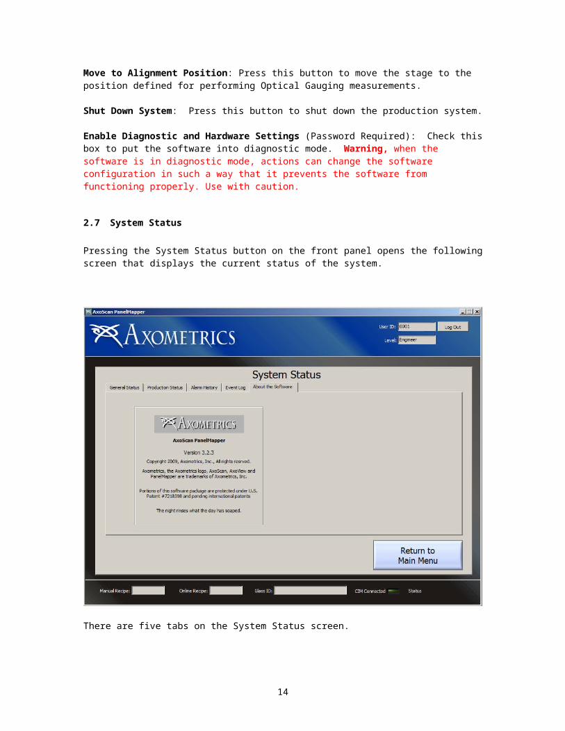
Move to Alignment Position: Press this button to move the stage to the position defined for performing Optical Gauging measurements.
Shut Down System: Press this button to shut down the production system.
Enable Diagnostic and Hardware Settings (Password Required): Check this box to put the software into diagnostic mode. Warning, when the software is in diagnostic mode, actions can change the software configuration in such a way that it prevents the software from functioning properly. Use with caution.
2.7 System Status
Pressing the System Status button on the front panel opens the following screen that displays the current status of the system.
There are five tabs on the System Status screen.
2.7.1 GENERAL STATUS
12

The general status shows the current state of the Axometrics Production Software. The general status is used by the software to determine which controls are enabled and disabled.
Also shown is the current index used when autosaving files. This number is usually included in the filename, in increments by one each time a new file is saved (See Section ???).
2.7.2 PRODUCTION STATUS
The production status tab shows information related to the production communications. The Production interface is discussed in section 4.
2.7.3 HARDWARE STATUS.
13

The Hardware Status tab shows information related to the physical hardware on the production system.
Sensors Monitor: This indicator shows the current state of all the PLC channels in the system.
Reconnect to Sensors: Press this button to reestablish a connection with the PLC in case communication between the production software and the PLC is lost.
PLC attached: This indicator shows whether a PLC is attached to the system.
AxoScan Status: This indicator shows the status of the AxoScan or AxoStep Sensors. For this indicator, when more than one sensor is used in the system (e.g. FAA systems). The status indicators from the individual sensors are combined using a logical OR operation.
Pin Lifter (If Installed): Shows the current state of the pin lifter
2.7.4 MULTI HEAD STATUS.
The operation on this tab is currently under development. Please ignore all controls on this tab.
2.7.5 ALARM HISTORY:
This tab shows a recording of all production alarms and warnings that the system has experienced. Nothing is recorded when the “Production Line Communication” is not enabled on the system (see Section 2.8.12).
14
2.7.6 EVENT LOG
This tab shows a log of all software events that occur during operation.
The event log can be configured to automatically write to disk in the settings (See Section 2.8.10)
Clear: Press this button to clear the on-screen Event History.Save: Press this button to save the Event History currently shown on-screen.
2.8 Edit Settings
Pressing the Edit Settings button on the Main Menu opens the System Settings screen shown below.
Note: if user login is required, this button item will be disabled unless an Engineer-Level user is logged in.
15

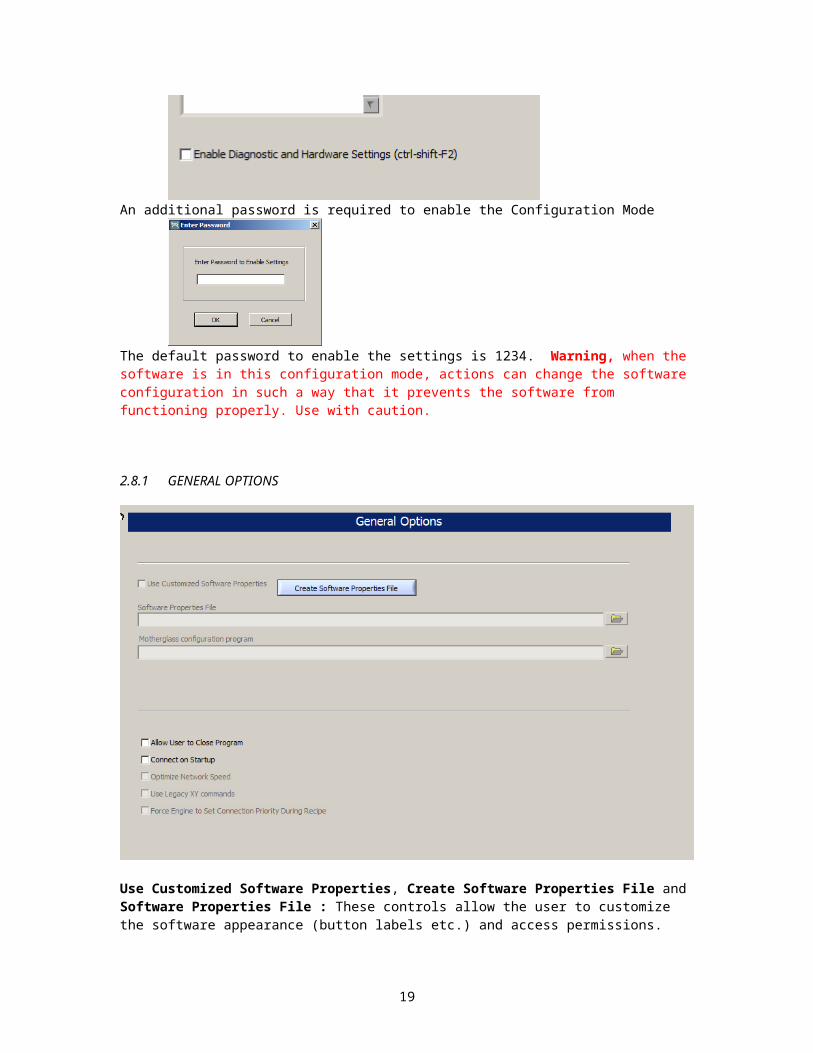
When the setting window is open, notice that many of the controls are disabled. This is because many of the controls are used to configure the system hardware and changing them can render the system inoperable. Nevertheless all disabled features can be unlocked by checking the box Enable Diagnostic and Hardware Settings
An additional password is required to enable the Configuration Mode
The default password to enable the settings is 1234. Warning, when the software is in this configuration mode, actions can change the software configuration in such a way that it prevents the software from functioning properly. Use with caution.
16

2.8.1 GENERAL OPTIONS
Use Customized Software Properties, Create Software Properties File and Software Properties File : These controls allow the user to customize the software appearance (button labels etc.) and access permissions. Contact Axometrics for information about customizing software properties.
Motherglass configuration program: For production line systems that measure un-diced motherglass samples, a customer specific configuration program for setting up measurement locations can be defined here..
Allow User to Close Program: Enables the Close button (the × in the upper right hand corner of the window).
Connect on Startup: When this box is checked the production software will try to establish a connection with the hardware on startup.
Optimize Network Speed: Check this box to remove the network latency that occurs with remote computers. (Generally only used on FAA-3 systems).
Use Legacy XY commands: Checking this box causes the system to use the older three command XY movement (only necessary on old systems).
Force Engine to Set Connection Priority During Recipe: When this box is checked, a command is sent to the AxoScan engine during measurement that forces the engine to give priority to commands from the production software
17

2.8.2 CALIBRATION OPTIONS
Number of measurements to average for orientation baseline: Should be set to a number greater than 20, generally a value of 50 to 100 is recommended.
Calibration Wavelength: This is the wavelength that the calibration is performed at.
Calibration Program (Configuation Mode): This is the path to the program that is used for calibration.
Calibration Program T2 (Configuation Mode): When the production software is configured for independent turrets, this is the calibration program that is used for Turret 2.
Calibration Behavior: Use this control to select the behavior of the system calibration. There are two options available.
1. Perform Calibration as a Single Step: This is the default setting and it configures the system to perform both a calibration (ot test) in air, followed by a calibration (or test) on the reference sample. The XY stage will move between steps.
2. Perform Calibration in Two Steps: Use this setting when the Axometrics software does not have direct control of the XY stage. This allows the user to perform the calibration steps individually while performing a manual move
Automatically Calibrate System: When this box is checked the software will automatically perform a calibration at the intervals defined. The system will only calibrate when it is in ready mode (not measuring). Before an automatic calibration occurs, the following dialog box appears giving the user 30 seconds to postpone the calibration.
18

Calibration Log File: If a file is defined, information about every calibration will be logged to that file.
2.8.3 RECIPE OPTIONS
Recipe Options require Configuration Mode
Automatically Save Recipe Files (recommended): If this box is checked all recipe files will be automatically saved by the software. Otherwise, the user must manually save each recipe when it is created or edited.
Automation Recipe Index File: Location of the index file for the Automation recipesManual Recipe Index File: Location of the index file for Manual recipes.
Directory to Save Recipe File: The directory where all recipe files are saved to.
Delete Recipe Files: When this box is checked, the recipe files are deleted, rather than just deleting the recipe from the recipe index
2.8.4 DATA FILE OPTIONS
The settings on Data File Options page are configured as follows:
19
Translate output file after online measurement: When this box is checked, after an automatic measurement is performed, the production software will launch a Translation Program (configured in the Path to Data Translation Program control), that will automatically convert the data file to any desired format. Note: Data translation programs are developed by Axometrics on a case-by-case basis, and are generally customer specific.
Automatically Save All Files: When this box is checked all measurement files made in manual mode are automatically saved using the data file format defined when pressing the “Modify data file format” button. Note: Automatic measurements are always saved regardless of the state of this check box.
Reset Autosave Index: Press this button to reset the autosave index to 1. Note: the autosave index is incremented by one each time a file is saved.
Modify data filename format: Press this button to open the filename format dialog box that allows the user to change the format of the filename that is used when autosaving data.
Directory to Auto-Save Data Files: This path control allow the user to set the directory that Auto-Saved data files are stored.
Path to Data Translation Program: If a data translation program is included, it’s location will be set with this control
2.8.5 FILENAME FORMAT DIALOG
The filename format dialog window is shown below
20

Use this window to configure the format of automatically saved data files. Several keys are available that include such items as the Glass ID, Recipe ID, and User ID, as well as keys for the time and date. The default value for the file format is
%8n
this will create the filename as an 8 character string that represents the current autosave index. for example if the autosave index is at 17 then the next file to be saved will have the following filename:
00000017.csv
2.8.6 HARDWARE OPTIONS
The following options are available on the Hardware Options page.
21

Path to AxoScan or Remote Startup Program: For systems that only have a single sensor and the AxoScan control comuter is also the master computer, this will be the path to the AxoScan (or AxoStep) Engine. For multi-sensor system, where the master computer is separate from the AxoScan control unit computers, this path will point to a remote startup program.
Remote Initialization and Shutdown Program: Checking this box tells the software that a remote startup program is being used, and also makes another path control visible.
Path to AxoScan Shutdown Program: For multi-sensor system, where the master computer is separate from the AxoScan control unit computers the software system cannot be shutdown directly using the productions software, a separate shutdown program needs to be launched. Define the location of that program with this dialog box.
Control Signal Tower: Check this box if you want the production software to directly control the signal tower.
XY Stage Control Utility: This control sets the location of the XY Stage control program that is launched when pushing the XY Table Control Button on the Other Functions Screen in the main window. (Section 2.6).
22

Tip Tilt Control Utility: This control sets the location of the Tip/Tilt Control program that is launched when pushing the Tip/Tilt Control Button on the Other Functions Screen in the main window. (Section 2.6)
Camera Stage Control Utility:(not shown) This control sets the location of the Camera Stage control program that is launched when pushing the Camera Stage Control Button on the Other Functions Screen in the main window. (Section 2.6).
2.8.7 FIXTURE OPTIONS:
This page is used to configure the fixture type on the production system that the software is controlling. Warning, the settings on this page are specifically configured for the production hardware being used. Changing these settings could render the system inoperable.
Number of Turrets: Use this control to select the number of turrets on the production system. If a system has only one turret, that turret is necessarily designated “Turret 1” when configured below.
Independent Turrets: Check this box is the fixture and/or the sensor each turret is different. When this box is checked recipies become dependent on the turret being used, and only one turret can be used in a given recipe.
Alternate XY: Check this box if the XY stage is NOT being controlled by and AxoStep or AxoScan Engine, but an independent piece of software.
Alt XY IP: This is the IP address of the Alternate XY control software
23

Comm Port and Status Port, are the communication and status TCP/IP ports for the alternate XY control software respectively.
Beam Configuration: This is used to set the possible beam configuration for the system. Three options are available:
1. Transmission Only: Fixtures such as the APM that can only measure in transmission 2. Transmission and Reflection: Fixtures such as the VRTF which can measure in both
transmission and reflection.3. Reflection Only: Fixtures such as the VVRM that can only measure in reflection (this
does not count calibration)
2.8.8 TURRET 1 / TURRET 2
Sensor Type (AxoScan or AxoStep): This control sets the sensor type used in the production system.
Fixture Type: This sets the fixture type of the production hardware: There are two Fixture Type options:
Single Sensor Turret: This is for systems with a single sensor mounted to a movable turret (such as an APM-system). For a Single Sensor Turret, the available controls are shown above.
IP Address for AxoScan (or AxoStep): This is the IP address for the AxoScan Engine that is controlling the sensor. If the master computer and the AxoScan Control unit computer are the same then the value of 10.0.0.20 should be used (127.0.0.1 also works).
Ethernet Port for AxoScan (or AxoStep): This is the main communications port for the AxoScan (or AxoStep) Engine. In all but a few rare cases the default values of 5000 for AxoScan and 55000 for AxoStep are used.
24

Status Port for AxoScan (or AxoStep): This is the status communications port for the AxoScan (or AxoStep) Engine. In all but a few rare cases the default values of 5002 for AxoScan and 55002 for AxoStep are used.
Multiple Sensor Turret: If a Multiple Sensor Turret fixture type is chosen the Fixture Options page appears as in the image shown below.
In this case, the network locations for each of the AxoScan control unit computers and the mounting angles for each of the sensors is specified..
Control: Only one AxoScan unit can be designated as a Control. This is the AxoScan unit that controls the robotic stages and the light source in the production system. It is typically the on-axis AxoScan system (AxoScan 2 above).
Rotation Motor: Check this box if the system has a motor for performing rotation. If this box is checked, entries for fixed rotation angles are not visible.
Tilt Motor: Check this box if the system has a motor for performing variable tilt measurements. If this box is checked entries for fixed tilt angles are not visible.FAA loop timing (ms): This control is used for diagnostic purposes and should not be changed without consulting Axometrics.
2.8.9 CALCULATION OPTIONS:
All data fitting and measurement reporting is performed using user configurable dynamically linked libraries (*.dll). These libraries are configured on the Calculation Options page.
25

Calculations: This shows a list of currently available calculation subroutines.
Add: Press this button to add a new calculation dll into the production software. When the library is successfully added, you will be prompted to provide the name of a viewer program to be associated with the calculation dll. For example with the LCD Panel Measurement routine, the associated viewer is LCDView.
Remove: Press this button to remove any calculation dll from the production software.
Check: Press this button to perform a simple check of the installed dll currently selected in the Calculations list. If the dll is functioning properly the name of the will appear in the box at the top
DLL Location: Shows the file location of the dll used for the calculation.Viewer Path: Shows the file location of the viewer program associated with the calculation dll.
26

return type: is used for diagnostic purposes
Measurement Recipe Function: This control is currently not used.
2.8.10 EVENT LOGGING
This page is used to configure the files used for logging events and alarms to disk automatically.
Log alarm history to file: Check this box to log all production alarms to the file specified in the control Error Log File.
Error Log File: This is the name of the file that will store all production alarms and warnings produced by the production software.
Alarm Definition File: This is a file that associates the numerical production alarm and warning codes with physical descriptions, and resolution information.
Log event history to file: Check this box to log all production software event entries to disk. These events will be logged in the file specified in the control Event Log File
Event Log File: This is the name of the file that will store the event history as it occurs in the production software.
2.8.11 SAMPLE GAUGING OPTIONS
Two types of sample gauging are available:
Optical Gauging: Sample placement is not critical during measurement. Cameras are used to analyze alignment marks on the sample, and measurement coordinates and results are adjusted accordingly to account for the sample position and orientation.
Mecanical Gauging: After the sample is loaded, a mechanical gauging system is used to position the sample in the correct location for measurement.
27

Enable Optical Gauging Alignment system: Check this box to enable the optical gauging system (if installed)
Camera Stage Installed: Check this box if one of the optical gauging cameras is attached to a linear stage.
Number to average for Optical Gauging alignment: This sets the number of optical gauging measurement to perform when obtaining the data used to correct the measurement coordinates and adjust the measured results. Typically this number does not need to be very large since the optical gauging is usually extremely precise.
Query Optical Gauging: Press this button to query the last measurement from the optical gauging software.
Path to Optical Gauging Engine Program: This is the file location for the program that controls the optical gauging system (different optical gauging systems use different programs)
IP Address for Optical Gauging: This is the IP address used for communication with the Optical Gauging software. Typically the optical gauging software is installed on the master computer so the IP address is usually 10.0.0.20 (the localhost IP address also works in this case 127.0.0.1).
Ethernet Port for Optical Gauging: This is the Ethernet port used for communication with the Optical Gauging software. The default value is 5100. Only in rare cases will this value be different than the default.
Enable Mechanical Gauging Alignment System: Check this box to enable the mechanical gauging system.
28

MG PLC Control 1 and MG PLC Control 2: These controls are use to the the M-Devices used to activate the mechanical gauging.
MG PLC Output ON 1, MG PLC Output ON 2: These are the Y devices that control the pneumatic solenoids that turn on the Mechanical Gauging
MG PLC Output OFF 1, MG PLC Output OFF 2: These are the Y devices that control the pneumatic solenoids that turn off the Mechanical Gauging
MG Timing: number of Milliseconds to wait between engaging and disengaging the mechanical gauging solenoids.
Apply Mechanical Gauging whenever Pins are Lowered: Check this box to apply the mechanical gauging whenever the pins are lowered.
Hold Gauging: When this box is checked, the Mechanical gauging will not automatically release and will hold the sample in place until the measurement is complete.
2.8.12 PRODUCTION LINE
This Page is used to configure the settings for production line communication
Enable Production Line Mode: Check this box to enable the production line communication.
Communication port for CIM: This is the port that the production software listens on for connections by a CIM computer.
PLC Sensors Definition: This is a path to the file that describes each PLC input and output port.
IP Address for PLC: This is the IP address for the PLC (If Installed). The PLC on Axometrics production systems is typically configured to be 10.0.0.70. If no PLC is installed this entry will contain the word “NONE”
29

Ethernet Port for PLC: This is the Ethernet port that the PLC uses for communications (typically port number 20000 is used).
PLC Connection Timeout (s): This is the length of time to wait for a PLC communication. If this time is exceeded, communication with the PLC will be dropped (and an alarm will be reported)
Generate Alarm for Bad Data: Check this box if you want the production software to generate and alarm (blinking signal tower, buzzer etc.) when data is measured outside of parameter limits.
2.8.13 MANAGE USER ACCOUNTS
User accounts can be configured on the Manage User Accounts page. The Axometrics production software has three levels of user accounts.
1. Engineer: An engineer has access to all functions on the production software (although some settings require a password to change). This includes making recipes system calibration and changing settings.
2. TA-1 (Technician Account-Level 1): Technician level accounts only allow the user to load recipes and perform measurements.
3. TA-2: This account type currently has the same access as the TA-1 type (it is reserved for future development)
If the software is configured such that user accounts are not required, then the software behaves as if an engineering level user is logged on at all times.
The controls used to manage user accounts are shown below:
Require Operator Log In: If this box is checked, user login is required to operate the software.
Log In Requirement: There are two settings possible for the Log In Requirement1. Username and Password: The user must correctly enter their username (or Operator ID)
and corresponding password to log in to the software.
30

2. Password Only: For this option, the user can select their username from a pull-down lit of options and must only enter their password to log in.
New User: Press this button to create a new user.
Delete User: Press this button to delete the user that is currently selected in the User Accounts table
Edit User: Press this button to edit the user account that is currently selected in the User Accounts table
Password file: This path control has the location of the Password file that contains all of the user account information.
Creating a New User
When the user presses the New User button, or the Edit User button, the following dialog box appears to edit an existing account or to create a new account.
31

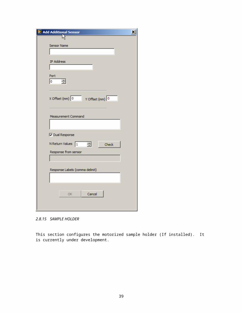
2.8.14 ADDITIONAL SENSORS
This section is used to configure additional sensors attached to the system. It is still under development.
32

2.8.15 SAMPLE HOLDER
This section configures the motorized sample holder (If installed). It is currently under development.
33

34
3 SETTING UP A MEASUREMENT RECIPE
Pressing the Recipe Library button, opens the recipe editor screen shown below (in production mode).
In Production Mode two recipe tables are used, one table is used for manual measurements, and a second table is used for On-Line recipies.
In Standard Mode, only the Manual Recipies Table is shown.
There are 9999 possible recipes that can be configures for both On-Line Recipies and Manual Recipies.
Add: Creates a new recipe. When the user presses the Add button the following dialog box appears allowing the user to select the desired recipe number from. Once a recipe is configured, its recipe number is no-longer available to be selected.
35

After selecting a Recipe Index, the main window of the recipe editor is displayed.
Recipe Name: Notice that there is a text entry box next to the Recipe Number for the Recipe Name. Users are highly encouraged to give each recipe they create a name to make selecting recipes easier.
Calculation Type: This pull-down box is used to select the calculation subroutine used for the recipe being created. Calculation types are configured in the Calculation Options page in the Main Settings (Section 2.8.9). Note: Once a recipe has been created, the Calculation Type cannot be changed. If you want to change the Calculation Type, you need to create a new recipe.
Recipe Name
36

Sample Settings: Press this button to configure the sample settings. Note: the Sample Settings are determined by the Calculation Type set in the main window.
Measurement Settings: Press this button to configure the measurement settings for the recipe. This includes the XY coordinates, Tilt and Rotation coordinates and Wavelength value.
Other Settings: Press this button to configure additional measurement settings such as Optical Gauging, Temp Settings, etc.
Number to Average at Each Point: Use this control to set the number to average for each measurement.
Recipe Description: Use this box to provide a brief description of the measurement being made. Users are encouraged to provide a description of each recipe created to make selecting recipes easier.
Accept: Press this button to accept the recipe and save it in the library. When the settings have been configured enough to make the recipe valid, this control will be enabled.
Cancel: Press this button to discard the current recipe.
3.1 Sample Settings
The sample settings will be different depending on the Calculation Type for the recipe being created. The following section is for the calculation type “LCD Panel Measurement”. Instructions for additional calculation types are included in the appendices.
After pressing the Sample Settings button, the Sample (Calculation) window appears (This window will be different for different calculation types)
37

Select the buttons at the top of the screen to select various setting pages.
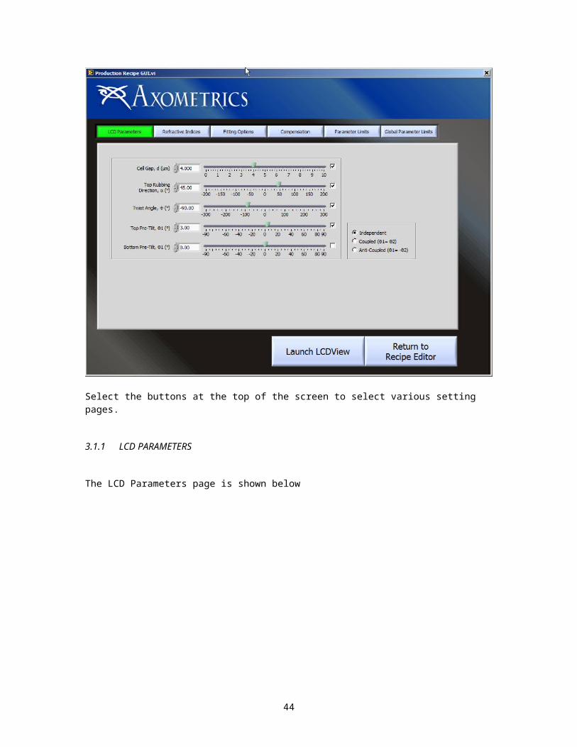
3.1.1 LCD PARAMETERS
The LCD Parameters page is shown below
38

To determine the optical properties of the LCD panel being measured, production software fits the measurement data to five (5) free variables.
Cell Gap: The thickness of the LC layer in the LC cellRubbing Direction: The rubbing direction on the top surface of the LC cell. This quantity physically corresponds to the director orientation of the top layer of the LCD structure.Twist Angle: The amount the LC directors twist between the top and bottom surface of the LC cell.Front Pre-Tilt: The angle that the LC director tilts into the sample at the top surface of the LC cell.Back Pre-Tilt: The angle that the LC director tilts out of the sample at the bottom surface of the LC cell
These values are set using the LCD Properties Control, shown below:
Values can be changed by adjusting the sliders in the control, or manually entering values. The user also has three options for coupling the front and back pre-tilt angles.
Independent: Front and back pre-tilt angles are independent valuesCoupled: Front pre-tilt and back pre-tilt are the same value.Anti-Coupled: Front pre-tilt is the negative of the back pre-tilt
3.1.2 REFRACTIVE INDICES
The Refractive indices page is shown below
Refractive index data is provided by the user and is shown on the tab control at the bottom of the screen. Pressing the Edit Refractive Index button on the tab control brings up the refractive
39
index dispersion control allowing the user to configure the refractive index dispersion of the LCD being measured.
The refractive index data in LCDView is represented using a Cauchy expansion, of the form:
,where the wavelength λ is expressed in nanometers.
Using the Refractive Index Dispersion Control, the user can directly enter the Cauchy terms, or enter the refractive indices at several different wavelengths in the table. If the refractive indices are entered manually, click the Find Cauchy Terms Button to determine the Cauchy Coefficients for the refractive index data. For more information on the Refractive Index Dispersion control, see Section 4.3 in the LCDView Users Manual.
3.1.3 FITTING OPTIONS
Also, on the tab control, the user can set the Fitting Options used in the LCD calculation.
The Fitting Options Tab gives the user two options for setting the number of layers, and thereby determines the simulation accuracy.
40

Adaptive Layer Count: LCDview uses an iterative algorithm to determine the type of LC cell, and adaptively determines the optimum number of layers necessary to accurately represent the inhomogeneous variation of the LC cell.
Manual Layer Count: The user can manually enter the number of layers used for the simulation.
In general, it is recommended that the user use the Adaptive Layer Count option when fitting LC data. However, if unusual results are obtained, the user might want to consider using the manual layer count.
There are also additional options that can be set by the user
Max Iterations is the maximum number of iterations that the optimization algorithm will use to fit the data
Tolerance is a parameter used by the algorithm to determine when to stop the optimization procedure.
Remove blocked data points: If this box is checked the software will remove any data points that are blocked (by support rails for example) from the data fitting calculation and only use unblocked values.
Transmission Threshold (% of Max): This is the threshold that is used to determine when to remove a blocked data point. It is given as a percentage of the Maximum Transmission that is measured in a given data set. Since the transmission for all tilt and rotation angles should be within a few percent of each other, a data point that is less than say 10% of the maximum transmission measurement can be safely rejected since it is most likely either fully or partially blocked..
Include Panel Bending: Check this box to include panel bending in the data optimization. Panel bending information is obtained through additional sensors (such as an autocollimator) that are included on some systems.
3.1.4 COMPENSATION
A section is included for sample compensation
41

Color Filter Rth (nm): On VA-type cells, the color filter can have a significant effect on cell gap measurements. Here the user can enter a compensation factor for the effects of the color filter. Typically the Rth of the isolated color filter is measured off line, and is entered here.
Color Filter Facing Up: Select this when the color filter is facing the PSG
Color Filter Facing Down: Select this when the color filter is facing the PSA
Cell Gap Correction: An option is given for applying a linear correction factor to the cell gap measurement. The correction factor is given as a linear offset of the form
New Cell Gap = A*(Old Cell Gap)+B
where the values of A and B are provided by the user.
3.1.5 PARAMETER LIMITS
Measurement Parameter Limits are configured on the Parameter Limits Page.
Parameter Limits can be configured for each of the 5 measured values in the LCD Panel Measurement calculation. Parameter limits are configured as follows:
Max Value: Registers a bad measurement if the parameter exceeds this valueMin Value: Registers a bad measurement if the parameter is less than this value
Active: Check this box to enable parameter limit checking on each measurement. Parameter limits are ignored if this box is un-checked
3.1.6 GLOBAL PARAMETER LIMITS
42

The LCD Panel Measurement Calculation also allows the user to set global parameter limits. These are limits that are placed on the variation of the parameters over all measurements performed in the recipe.
Global parameters can be configured in one of 3 ways
Range (Max-Min): Registers an alarm if the Maximum measured parameter – minimum measured parameter (over all measurements performed by the recipe) exceeds the value entered.
St.Dev (σ): Registers an alarm if the standard deviation of the parameter (over all measurements performed by the recipe) exceeds the value entered.
CV%: Registers an alarm if the Critical Value percent (100*St.dev/average) of the parameter (over all measurements performed by the recipe) exceeds the value entered.
3.1.7 LAUNCH LCDVIEW
The user can also launch LCDView to set up the calculation recipe. Refer to the LCDView user’s manual for more information on fitting LCD data using LCDView.
3.2 Measurement Settings
Setting up a measurement recipe requires configuring the three primary measurement variables used production system:
x,y Coordinates: The list of positions on the panel that are measured.Tilt, Rotation Angles: The tilt and rotation angles that are measured at each pointWavelengths: The wavelengths used at each measurement
43

When the Load Measurement Recipe Button is pressed on the front panel, the LCD Measurement Recipe Builder window opens, which allows the user to configure the measurement recipe.
The following sections describe the steps necessary to properly set up a measurement recipe
3.3 x,y Coordinates Setup
The first tab on the LCD Measurement Recipe Builder allows the user to setup the x,y Coordinates that will be used for the measurement. (Note: Cell Number is optional)
The x-y coordinates can be expressed in one of two ways
1. Absolute coordinates: The values in the coordinate list are the actual position values of the x-y stage motors.
2. Panel coordinates (only available with Panel Alignment machine vision system): The values in the coordinate list are measured from the lower left alignment mark on the LCD panel being measured, and the x-axis is the line joining the two alignment marks on the panel. The measurement locations illustrated on the x-y coordinates tab shown above are drawn using the last successful panel alignment measurement. The actual motor location are adjusted accordingly each time an alignment measurement is performed. Therefore, even if the panel is repositioned in the panel holder, the same location on the panel is measured.
The relationship between panel coordinates and absolute coordinates is illustrated below.
44
Panel Coordinates
Absolute (Stage) Coordinatesoffset x
offset yPanel Coordinates
Absolute (Stage) Coordinatesoffset x
offset y
The user has three options for setting up these coordinates.
Load From File: The user can load a tab delimited file of x and y coordinates that will be imported into the table.
Enter By Hand: If the user presses the Enter By Hand button, the following window appears, allowing the user to manually enter x,y Coordinates.
Wizard: If the user presses the Wizard button, the Map Setup Wizard window appears, allowing the user to easily configure the x,y coordinates
45

The first step when using the Map Setup Wizard is to move the x,y table to the first measurement position on the panel by using the Jog controls or manually entering the Coordinates and pressing the Move button, or by dragging the cursor in the window. Once the x,y table is in the
correct position, press the button. Then press the
button
Once the first position has been set, the text above the button changes to “Step 2” and the text on the button also changes indicating that the user move the x,y table to the opposite corner of the desired measurement area, which will correspond to the second position. Once the x,y table is in
the second position, press the button. Then press the
button
Once both positions have been selected, the following control appears, allowing the user to set the number of points in the measurement. In the example shown below, the user has selected an array of 3 points by 3 points (9 total measurement positions) whose corners are defined by the two points previously selected by the user.
46

Once the array of points is defined, they are shown on the screen and the Finish button is shown. Pressing the Finish puts those values in the XY coordinates table on the Measurement Settings Page.
Note: When the user selects Panel Coordinates, the two alignment marks appear in the window, allowing the user an easy reference for navigating the panel. All the controls on the window are also converted to panel coordinates, except the cursor window, which always shows the absolute position of the motor stages.
3.4 Tilt, Rotation Angles
The Tilt and Rotation Angles that are available for configuration is highly dependent on the measurement fixture of the system being used.
3.4.1 APM TURRETS
For systems with both tilt and rotation motors (APM-type) the following controls are available for setting the tilt and rotation angles
47

There are four methods for configuring the tilt and rotation angles for an APM-type turret.
Load From File: Press this button to open a file dialog to load a comma delimited text file that contains the Azimuth and Polar Angles to be measured.
Enter By Hand: Press the Enter By Hand button to open the following dialog box allowing the user to enter the Azimuth and Polar Angles by hand.
Tilt Wizard: When this button is pressed, the following window appears.
This utility allows the user to enter polar angle scans along arbitrary rotation angles. The rotation angles can be entered manually, or the user can enter equally spaced rotation angles.
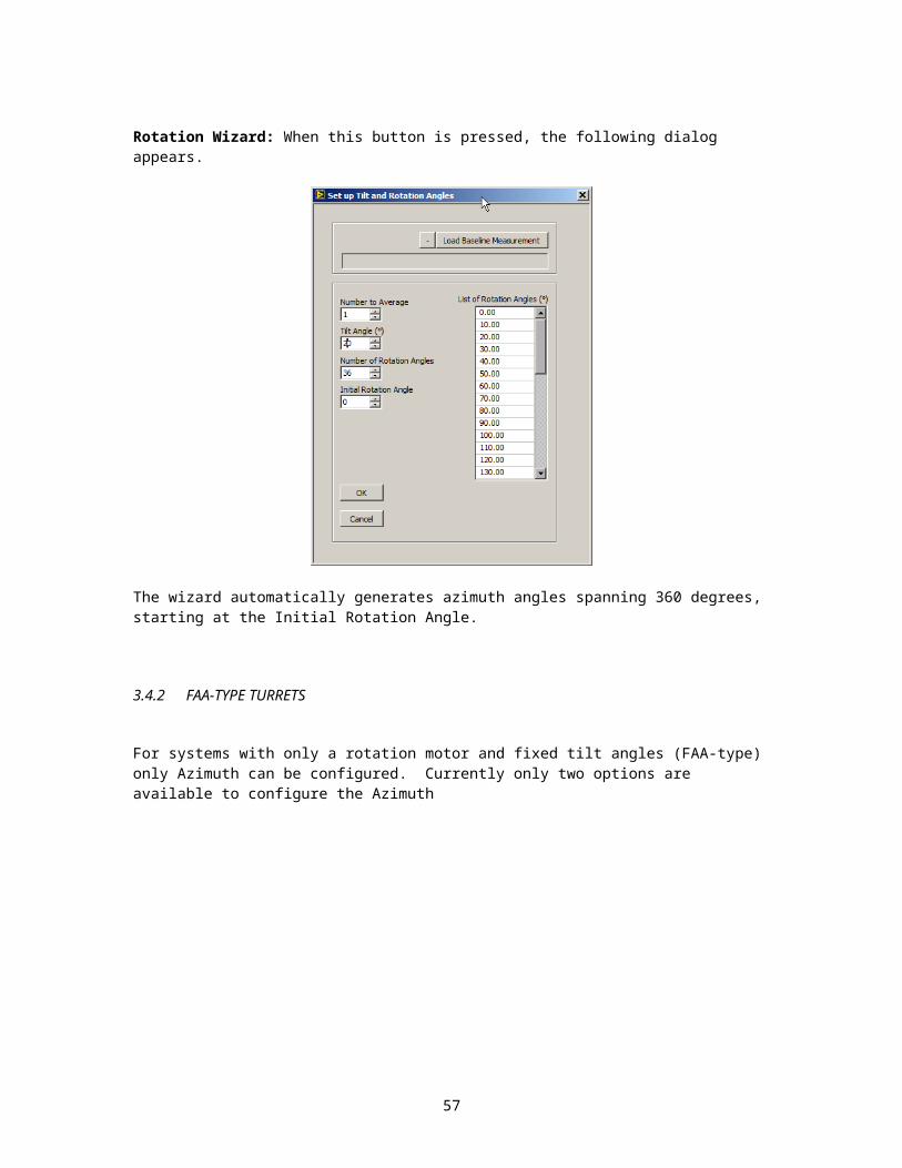
Rotation Wizard: When this button is pressed, the following dialog appears.
48

The wizard automatically generates azimuth angles spanning 360 degrees, starting at the Initial Rotation Angle.
3.4.2 FAA-TYPE TURRETS
For systems with only a rotation motor and fixed tilt angles (FAA-type) only Azimuth can be configured. Currently only two options are available to configure the Azimuth
Load from File: Press this button to load a list of Azimuth angles from a text file.
49

Enter by Hand: Press this button to manually enter the Azimuth Angles
Note that the Fixed Tilt Angles are displayed for reference purposes.
3.4.3 FAF-TYPE TURRETS
For systems with fixed polar angles and fixed azimuth angles (FAF-type) there is nothing to configure. A table showing the fixed tilt and rotation angles is displayed for reference
3.5 Wavelengths.
The third tab on the LCD Measurement Recipe Builder allows the user to setup the wavelengths that will be used for the measurement.
The polarimeter performs measurements at the wavelengths entered by the user. These wavelengths can be loaded from a file or entered by hand, using the following control.
50

If the user presses the Wizard button, the following control appears, allowing the user to setup the wavelengths automatically.
51

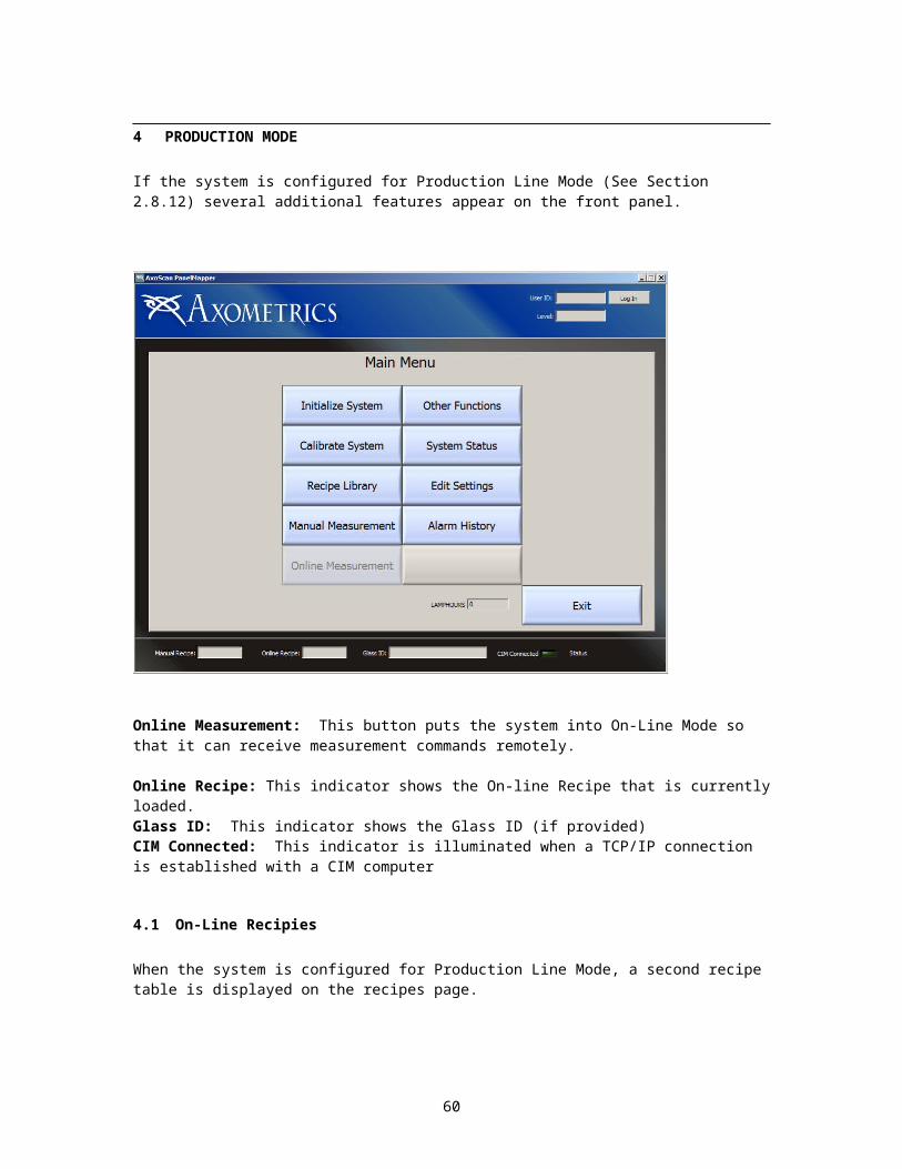
4 PRODUCTION MODE
If the system is configured for Production Line Mode (See Section 2.8.12) several additional features appear on the front panel.
Online Measurement: This button puts the system into On-Line Mode so that it can receive measurement commands remotely.
Online Recipe: This indicator shows the On-line Recipe that is currently loaded.Glass ID: This indicator shows the Glass ID (if provided)CIM Connected: This indicator is illuminated when a TCP/IP connection is established with a CIM computer
4.1 On-Line Recipies
When the system is configured for Production Line Mode, a second recipe table is displayed on the recipes page.
52

On-Line Recipes are configure in an identical manner to manual recipes. Additionally On-Line recipes can be copied from Manual Recipes (and vice-versa).
Note: Only On-Line Recipes are available to the CIM computer for measurement.
4.2 Production Status
When Production Line Mode is enabled, the status of the Production communications can be monitored on the Status page (See Section 2.7).
53

The following a description of the indicators on the Production Status Tab.
Running, Ready and Alarm/Down: This indicates the current state of the system. 1. The Running light is illuminated when the system is actively measuring2. The Ready light is illuminated when the system is in currently operating properly but not
actively measuring3. The Alarm/Down light is illuminated when there is a problem with the system that
prevents it from making a measurement.
Ready to Measure, Safe to Load, Safe to Unload, Measurement Complete and Glass Present indicate the current condition of the machine. These are described below in Section 4.6.
CIM Connected: This light is illuminated when a connection is established on the production line listening port (typically 50000).
Sensors (PLC) connected: This light is illuminated when a connection has been established with the system sensor monitor (typically a PLC)
AxoScan Status Connected: This light is illuminated when a status connection has been established with all sensor head on the system.
Enable_Status: This light is illuminated when the ENABLE_STATUS command has been issued causing the Production software to send unsolicited messages when any production status change occurs.
Alarm Info: This indicator shows a list of all active alarms and warning.
Production Log: This indicator shows a log of all Production Activities.
54

4.3 System Control
The communication system is configured using two state variables (Mode and OperationMode)
Mode: Refers to the connection status between the client computer (ex. CIM computer) and the APS software and it can be in one of two states
Offline: There is no command and response available between the CIM PC and the APS PC:
Online: There is communication between the CIM PC and the APS PC. This communication might be limited depending on the state of the OperationMode variable
OperationMode: Refers to how measurements data is acquired the OperationMode variable can also be in one of two states:
Auto: All measurement and control of the equipment is performed using ithe CIM computer
Manual: All measurement and control of the equipment is performed with the User Interface of the Axometrics Production Software
Based on the value of the Mode and Operation Mode variables the system control is shown in the following table:
Mode OperationMode Comments Perform Measurement
Change Recipe
Report Data to CIM
Create Recipe
Online Auto System Completely Controlled By CIM CIM CIM Yes NoOnline Manual System is controlled by user, but data and
status are reported to CIMUser User Yes Yes
Offline Auto Disallowed - - - -Offline Manual System is controlled by user, but data and
status are not reported to CIMUser User No Yes
4.4 TCP Communication
Once the Axometrics Production software starts, it creates a listener on TCP port 50,000 (0xC350). The software will only allow one connection (Client) at a time. After a connection is established, the APS software continuously listens for commands on this port.
The table below shows the basic specifications for communication with the APS Software.
Item SpecificationProtocol TCP/IPPhysical Layer Ethernet (IEEE 802.3)Communication Speed 100 Mbps (or higher)Topology One ConnectionCommunication Port 50000 IP Address 10.0.0.20Message Format AsciiCommand Serial Number 0001-9999Meas. Data Format *.csv fileMeas. Data Transfer Shared DirectoryConnector RJ-45 (8-pin)
55

Typically, the APS Software acts as a server. Typically, it receives an incoming command from the Client software (the CIM software in this case), processes the command, and returns a response
If the APS Software receives an “ENABLE_STATUS” command, then the software will also send Status Message updates to the Client automatically any time there is a change in the instrument status.
4.4.1 COMMAND FORMAT
All commands and responses are sent in ASCII text format.
The command format is:
STX Serial Number (4 char) Command or Response ETX0x02 0x03
All messages and responses begin with a “Start of Text” character (‘STX’ = 0x02 = CHR$[02] ) and end with an “End of Text” character (‘ETX = 0x03 = CHR$[03] ). The ASCII text between the STX and ETX makes up the command or the response.
A serial number 0001 through 9999 must be prepended to the message by the client (sender). The serial number is included on the response sent back to the client. The serial number 0000 is reserved for the automatic Status Messages send to the client from the APS Software.
EXAMPLE: To send the ‘ONLINE’ Command and receive the ‘OK’ response, the Client and AxoScan would send the following ASCII characters:
Command (Client → AxoScan)‘STX’1234ONLINE‘ETX’ which is bytes:
STX Serial Number Command ETX0x02 0x31 0x32 0x33 0x34 0x4F 0x4E 0x4C 0x49 0x4E 0x45 0x03
Response (AxoScan → Client)‘STX’1234ONLINE_OK‘ETX’ which is bytes:
STX
Serial Number Response ETX
0x02
0x31
0x32
0x33
0x34
0x4F
0x4E
0x4C
0x49
0x4E
0x45
0x5F
0x4F
0x4B
0x03
Once AxoScan receives the ‘STX’ it will begin adding incoming characters to the command. If another ‘STX’ is received before the ‘ETX’ then previous command is deleted and a new command is started
4.4.2 RESPONSE MESSAGES
56

The response to most of the commands given in the table above will be of the form of a command echo followed by and underscore character “_”(0x5f) and then the response in the form given in the table above.
For Example, the command:
0002GLASS_ID=ABC4321DE
would generate one of the following responses:
0002GLASS_ID=ABC4321DE_OKor 0002GLASS_ID=ABC4321DE_ERR=0202
Additionally there are six additional response messages that are defined below:
1. Operator Message
When the CIM computer issues the GET_OPR command it is in the following format.
0002GET_OPR
This will generate a response which includes the operator message. The response will be in the following format
0002GET_OPR_{0x0D}{0x0A}[OPERATOR] {0x0D}{0x0A}OperatorID=123123123{0x0D}{0x0A} OperatorLevel=Engineer{0x0D}{0x0A}
Note: the two hex characters ({0x0D}{0x0A}) shown in green are the carriage return/line-feed (CR/LF) characters received when getting a multi-line response. Henceforth, the (CR/LF) characters will not be shown, and it will be assumed that multi-line responses from the APS computer will always include the CR/LF
4.5 Alarms and Warnings
Note: Alarms and warnings only occur when a Sensor Suite is connected to the Panel Mapper Software.
Depending on the system configuration, several different alarms and warnings can occur during the software operation.
The following definitions are used to differentiate between Alarms and Warnings:
Alarm: An alarm means that the system is in an abnormal state. When an alarm is triggered, the system is either automatically shut down, not functional, or there is risk that incorrect measurements might occur. (Example: the Emergency Stop Button is pressed)
Alarms have three levels of severity, which are used to determine how the CGM reacts to the Alarm.
57
1 = Alarm2 = Warning
Alarm Level (0,1 or 2) [0 for warning]
Description Code
Alarm level Reset Procedure Condition after Reset2 Full hardware and software restery needed Measurement aborts and must be started over1 User must press button on CGM software Measurement aborts and must be started over0 Resets automatically when alarm condition clears Measurement continues from where it paused
Warning: A warning means that the system is operating properly but a warning is issued to inform the CIM computer that the CGM is in a state where certain operations are un-safe to perform. (Example: the robot forks are in the CGM).
Each Alarm and Warning is given a unique 5 digit code. The code is as follows
1 1 005
Chapter 10 shows the list of possible alarms on the system. ( A complete list is dependent on the exact hardware configuration of the system)
All the current alarms and warnings are shown on the Factory control Tab of the the Panel Mapper software
Whenever a level 1 or a level 2 alarm occurs, a user acknowledgement is required to restore the system to a ready state. The following warning box appears that allows the user to acknowledge the alarm. If the Panel Mapper software is controlling the signal tower and audio alarm, the signal tower will flash and the alarm will sound until the user presses the Acknowledge button. If the alarm is still present, the system will go into a “down” state (red light not flashing, no audio alarm). Note: The system will not return to a “ready” state until the condition that caused the alarm has been resolved.
58

Level 2 Alarm
4.5.1 ALARM LOG
If a log file has been configured in the Production Software Settings (See Section 2.8.10) then the alarms and warnings will be logged to that file as they occur.
[Production Line Communication]Alarm Log Path= "/C/AxoView/Current Version/Alarms.log"
4.6 System StatesThe system states are based on the status of the PLC sensors, and machine status. The system State is determined by the following four values in the [Machine Status]
Ready to Measure: (TRUE or FALSE) Determines whether the system can receive the “Measure” Command from the CGM. If Ready to Measure is FALSE, an Error will Result from the CIM sending a “Measure” Command.
Safe to Load: (TRUE or FALSE) determines whether it is safe for a panel to be loaded into the system.
Safe to Unload: (TRUE or FALSE) determines whether it is safe for a panel to be unloaded into the system.
Measurement Complete: (TRUE or FALSE) tell when a measurement has been completed successfully. This value stays TRUE until the panel is removed from the system, or a subsequent measurement is attempted and fails.
Whether these values are TRUE or FALSE is determined by the sensors and logic in the system. The table below shows a typical example of how the system states are determined. The actual sensor logic that will determine the system states will change depending on the measurement system. However, only the four values in the system state need to be monitored to determine the action that needs to be taken to prepare the system for a measurement (load and remove samples, initiate measurements etc).
59

AxoScan Parked
Robot out of system Glass In
Door Open Mode Ty
pe* Ready to
MeasureReady to Load
Ready to Unload
Measurement Complete Description
Either Either Either Either Either A General AlarmTRUE FALSE FALSE FALSE Auto T Transient Load/UnloadFALSE TRUE TRUE FALSE Either T Measuring
Either Either TRUE Either Either A Mechanically UnsafeTRUE FALSE TRUE FALSE Auto T Transient Load/UnloadTRUE TRUE TRUE FALSE Auto A Measurement Alarm (Aborted)TRUE TRUE TRUE FALSE Manual N Panel installed (manual mode)
TRUE TRUE TRUE FALSE Auto TTransient measure (axoscan is parked)
TRUE TRUE TRUE FALSE Either A AxoScan Error
TRUE TRUE TRUE FALSE Manual N Meas Complete (Manual mode)TRUE TRUE FALSE FALSE Auto N FALSE TRUE FALSE FALSE Ready to Load Panel
FALSE TRUE FALSE TRUEFALSE TRUE TRUE FALSE
FALSE TRUE TRUE TRUERunning Idle FALSE TRUE Either FALSE Either T TRUE FALSE FALSE FALSERunning Idle FALSE TRUE Either FALSE Either T TRUE FALSE FALSE TRUE
TRUE TRUE TRUE FALSE Auto N TRUE FALSE TRUE FALSE Ready to MeasureTRUE TRUE TRUE FALSE Auto N TRUE FALSE TRUE TRUE Measurement is Complete
TRUE TRUE FALSE FALSETRUE TRUE FALSE TRUETRUE TRUE TRUE FALSETRUE TRUE TRUE TRUE
*Type: A=Alarm, T= Transient State, N= Normal State
Running
FALSE FALSE TRUE
FALSE FALSE FALSE FALSE
FALSE FALSE FALSE TRUE
FALSE
State Not Allowed
FALSE FALSE TRUE TRUE
Non-recipe stage motion
State Not Allowed
StatusAlarm/Down
IdleRunning
Alarm/DownIdle
Alarm/DownIdle
Alarm/Down
IdleIdle
IdleIdle
The system states can be monitored, either by software communication by sending the ‘GET_STATUS’ command. or they can be monitored through the PLC connection by reading the following PLC channels.
Channel PurposeY2B Safe to Load SampleY2C Safe to MeasureY2D Ready to MeasureY2E Measurement CompleteY2F Safe to Unload Sample
Since these channels are wired to an output module, the system can further monitor the hardware state of these three PLC channels.
An Example of the system state during a typical sample loading/measuring/unloading sequence is given below.
Safe to Load
Safe to Unload
Ready to Measure
Measurement Complete
Recipe Set RobotEnters
Measurement Finished
Signal Tower
GlassDetected
RobotLeaves
MeasurementStarted
RobotEnters
GlassRemoved Robot
LeavesRobotEnters
GlassDetected
RobotLeaves
Safe to Measure
Additional state diagrams for systems with a PLC are given in Section Error: Reference source not found.
4.6.1 USING THE AUXILIARY DAQ CABLE
60
When the Axometrics Hardware does not include a PLC, the Axometrics Production Software cannot use hardware sensors to determine System States. Therefore when the system states are reported to the client software it will be assumed by the production software that Safe to Load = TRUE and Safe to Unload = TRUE unless there is a measurement in progress. Furthermore, provided the system is not in an Alarm State, the production software will always be in a state of Ready to Measure = TRUE unless a measurement is in progress.
Safe to Load
Safe to Unload
Ready to Measure
Measurement Complete
Recipe Set MeasurementStarted
Measurement Finished
MeasurementStarted
Measurement Finished
Recipe Set MeasurementStarted
ALARM
ALARMAcknowledged
ProblemFixed
MeasurementStarted
MeasurementAborted
Signal Tower
Safe to Measure
61

5 USER ACCOUNTS
To operate the AxoScan PanelMapper software, a user login is required. A user can log-on either by pressing the User Log-On button on the front panel, or by swiping a keycard on the reader attached to the Panel Mapper system (for systems that are equipped with a key-card reader). If the user presses User Log-On on the front panel the software will prompt the user for a Username (or User-ID) and a password.
Currently there are three possible user accounts.
1. Engineer – The Engineer account level gives the user complete access to the instrument and all of it’s functionality.
2. TA2 (Technician Account Level 2) – This is a Technician Account level that gives the user limited access to the functionality of the instrument (Limited to performing measurements, and changing between pre-set measurement recipes)
3. TA1 (Technician Account Level 1) – Currently this account has the same access as the TA2 level.
The following table shows the access and functionality of the system based on the Account Level of the user that is logged in.
Online Auto
Online Manual
Offline Manual
Online Auto
Online Manual
Offline Manual
Initialize AxoScan Engine y y y n y yInitialize Panel Alignment y y y n y y
Panel Alignment Measurement n y y n y yAutomation Recipe n y y n y y
Automation Recipe - New Recipe n y y n n nAutomation Recipe - Edit Recipe n y y n n n
Automation Recipe - Delete Recipe n y y n n nMeasurement Settings n y y n n n
Calculation Settings n y y n n nSupport File n y y n n n
Baseline Measurement n y y n y yPerform Measurement n y y n y y
Online/Offline (user control) y y n* y y n*Auto/Manual Mode change (user control) y y n y y n
View Production Status y y y y y y
File>Exit n y y n y yOptions>Calibration Options n y y n n n
Tools>Manage User Accounts n y y n n nHardware>Control XY Stage n y y n y y
Hardware>Repostion the Moveable Camera n y y n y yHardware>Query Panel Alignment System n y y n y y
Hardware>Reset Panel Alignment n y y n y yHardware>Panel Alignment Options n y y n n n
Help>About n y y n y y
Engineer TA1/TA2
Front Panel Controls
Menu Items
*y (when CIM is connected)
If the user presses the Add User button, or the Edit User button, the following window appears allowing the user to edit the account settings.
62

There are two options for the Log-On Security Requirement.Only Password – When this option is selected, all of the user names are shown in pull-down menu. All that is required is that the user enter the appropriate password.
Username and Password – When this option is selected, the user must enter both the correct username and password to log-on to the system.
63

All of the user account information is stored in a file (APMAccounts.ini). The path to this file is configured in the AxoScan Panel Mapper.ini settings file (See Chapter 9)
64