· web viewblue text = designers notes. the designer must review and edit all blue text in this...
TRANSCRIPT

DESIGNER NOTES (to be deleted after reviewing):
1. This schedule contains minimum requirements. Do not delete applicable inspection tasks unless notes in blue indicate it is acceptable to do so.
2. Blue text = designers notes. The designer must review and edit all blue text in this schedule prior to inserting this schedule into the special inspections spec (UFGS 01 45 35).
3. Check section boxes with ANY inspection tasks applicable to your project. You may choose to delete unchecked sections or leave them in the scheduled unchecked.
4. Individual rows/tasks that that are not applicable to the project may be left in the section, as the inspector can determine whether they occur/apply (e.g. metal trusses in the light gauge framing section for example).
5. Design discipline sections are color coded for easier reference by designers. This schedule does NOT need to be printed in color.
6. When finished editing, delete this note box and save this schedule as a PDF and insert into the project specifications (special inspections section).
SCHEDULE OF SPECIAL INSPECTIONS (UFGS 01 45 35) REVISED FOR IBC 2015 ON 9/30/16
SCHEDULE OF SPECIAL INSPECTIONS
Reference UFGS 01 45 35 for all requirements not noted as part of this schedule.
INSPECTION DEFINITIONS:
PERFORM: Perform these tasks for each weld, fastener or bolted connection, and noted verification.
OBSERVE: Observe these items randomly during the course of each work day to insure that applicable requirements are being met. Operations need not be delayed pending these inspections at contractor’s risk.
DOCUMENT: Document, with a report, that the work has been performed in accordance with the contract documents. This is in addition to any other reports required in the Special Inspections guide specification.
CONTINUOUS: Constant monitoring of identified tasks by a special inspector over the duration of performance of said tasks.

SCHEDULE OF SPECIAL INSPECTIONS (UFGS 01 45 35) REVISED FOR IBC 2015 ON 9/30/16
A. STRUCTURAL - STEEL – WELDING SECTIONTHIS SECTION APPLICABLE IF BOX IS CHECKED: ☒
STEEL INSPECTION PRIOR TO WELDING – VERIFY THE FOLLOWING ARE IN COMPLIANCEIBC 1705.2.1, AISC 360-10: Table C-N5.4-1TASK INSPECTION TYPE1 DESCRIPTION1. Verify that the welding
procedures specification (WPS) is available
PERFORM
2. Verify manufacturer certifications for welding consumables are available
PERFORM
3. Verify material identification PERFORM Type and grade.4. Welder Identification System PERFORM The fabricator or erector, as applicable, shall maintain a
system by which a welder who has welded a joint or member can be identified. Stamps, if used, shall be the low-stress type.
5. Fit-up of groove welds (including joint geometry)
OBSERVE Joint preparation Dimensions (alignment, root opening, root face, bevel) Cleanliness (condition of steel surfaces) Tacking (tack weld quality and location) Backing type and fit (if applicable)
6. Configuration and finish of access holes
OBSERVE
7. Fit-up of fillet welds OBSERVE Dimensions (alignment, gaps at root) Cleanliness (condition of steel surfaces) Tacking (tack weld quality and location)
STEEL INSPECTION DURING WELDING – VERIFY THE FOLLOWING ARE IN COMPLIANCEIBC 1705.2.1, AISC 360-10: Table C-N5.4-2TASK INSPECTION TYPE DESCRIPTION8. Use of qualified welders PERFORM Welding by welders, welding operators, and tack welders
who are qualified in conformance with requirements.9. Control and handling of
welding consumablesOBSERVE Packaging
Electrode atmospheric exposure control10. No welding over cracked
tack weldsOBSERVE
11. Environmental conditions OBSERVE Wind speed within limits Precipitation and temperature
12. Welding Procedures Specification followed
OBSERVE Settings on welding equipment Travel speed Selected welding materials Shielding gas type/flow rate Preheat applied Interpass temperature maintained (min./max.) Proper position (F, V, H, OH) Intermix of filler metals avoided
13. Welding techniques OBSERVE Interpass and final cleaning Each pass within profile limitations Each pass meets quality requirements
1 PERFORM: Perform these tasks for each weld, fastener or bolted connection, and required verification. OBSERVE: Observe these items on a random sampling basis daily to insure that applicable requirements are met. Operations need
not be delayed pending these inspections at contractor’s risk.

SCHEDULE OF SPECIAL INSPECTIONS (UFGS 01 45 35) REVISED FOR IBC 2015 ON 9/30/16
A. STRUCTURAL - STEEL – WELDING SECTION (CONTINUED)STEEL INSPECTION AFTER WELDING – VERIFY THE FOLLOWING ARE IN COMPLIANCEIBC 2015 1705.2.1, AISC 360-10: Table C-N5.4-3TASK INSPECTION TYPE 1 DESCRIPTION14. Welds cleaned OBSERVE15. Size, length, and location of all
weldsPERFORM Size, length, and location of all welds conform to the
requirements of the detail drawings.16. Welds meet visual acceptance
criteriaPERFORM ANDDOCUMENT
Crack prohibition Weld/base-metal fusion Crater cross section Weld profiles Weld size Undercut Porosity
17. Arc strikes PERFORM18. k-area PERFORM When welding of doubler plates, continuity plates or
stiffeners has been performed in the k-area, visually inspect the web k-area for cracks.
19. Backing removed, weld tabs removed and finished, and fillet welds added where required
PERFORM
20. Repair activities PERFORM AND DOCUMENT
21. Document acceptance or rejection of welded joint or member
PERFORM
END SECTION
1 PERFORM: Perform these tasks for each weld, fastener or bolted connection, and required verification.DOCUMENT: Document in a report that the work has been performed as required. This is in addition to all other required reports.

SCHEDULE OF SPECIAL INSPECTIONS (UFGS 01 45 35) REVISED FOR IBC 2015 ON 9/30/16
B. STRUCTURAL - STEEL – BOLTING SECTIONTHIS SECTION APPLICABLE IF BOX IS CHECKED: ☒
STEEL INSPECTION TASKS PRIOR TO BOLTING – VERIFY THE FOLLOWING ARE IN COMPLIANCEIBC 1705.2.1, AISC 360-10: Table C-N5.6-1TASK INSPECTION TYPE 1 DESCRIPTION1. Manufacture’s certifications available for
fastener materialsPERFORM
2. Fasteners marked in accordance with ASTM requirements
OBSERVE
3. Proper fasteners selected for joint detail (grade, type, bolt length if threads are to be excluded from shear plane)
OBSERVE
4. Proper bolting procedure selected for joint detail
OBSERVE
5. Connecting elements, including appropriate faying surface condition and hole preparation, if specified, meet applicable requirements
OBSERVE
6. Proper storage provided for bolts, nuts, washers, and other fastener components
OBSERVE
STEEL INSPECTION TASKS DURING BOLTING – VERIFY THE FOLLOWING ARE IN COMPLIANCEIBC 1705.2.1, AISC 360-10: Table C-N5.6-2TASK INSPECTION TYPE 1 DESCRIPTION7. Fastener assemblies of suitable condition,
placed in all holes and washers (if required) are positioned as required
OBSERVE
8. Joint brought to the snug-tight condition prior to pretensioning operation
OBSERVE
9. Fastener component not turned by the wrench prevented from rotating
OBSERVE
10. Bolts are pretensioned in accordance with RCSC Specification, progressing systematically from the most rigid point toward the free edges
OBSERVE
STEEL INSPECTION TASKS AFTER BOLTING – VERIFY THE FOLLOWING ARE IN COMPLIANCEIBC 1705.2.1, AISC 360-10: Table C-N5.6-3TASK INSPECTION TYPE 1 DESCRIPTION11. Document acceptance or rejection of all
bolted connectionsDOCUMENT
END SECTION
1 PERFORM: Perform these tasks for each weld, fastener or bolted connection, and required verification. OBSERVE: Observe these items on a random sampling basis daily to insure that applicable requirements are met. Operations need
not be delayed pending these inspections at contractor’s risk.DOCUMENT: Document in a report that the work has been performed as required. This is in addition to all other required reports.

SCHEDULE OF SPECIAL INSPECTIONS (UFGS 01 45 35) REVISED FOR IBC 2015 ON 9/30/16
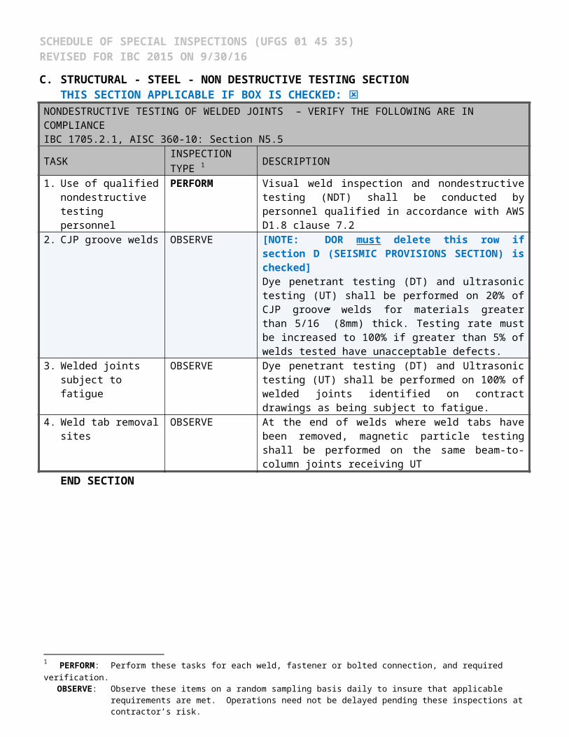
C. STRUCTURAL - STEEL - NON DESTRUCTIVE TESTING SECTIONTHIS SECTION APPLICABLE IF BOX IS CHECKED: ☒
NONDESTRUCTIVE TESTING OF WELDED JOINTS – VERIFY THE FOLLOWING ARE IN COMPLIANCEIBC 1705.2.1, AISC 360-10: Section N5.5TASK INSPECTION TYPE 1 DESCRIPTION1. Use of qualified
nondestructive testing personnel
PERFORM Visual weld inspection and nondestructive testing (NDT) shall be conducted by personnel qualified in accordance with AWS D1.8 clause 7.2
2. CJP groove welds OBSERVE [NOTE: DOR must delete this row if section D (SEISMIC PROVISIONS SECTION) is checked]Dye penetrant testing (DT) and ultrasonic testing (UT) shall be performed on 20% of CJP groove welds for materials greater than 5/16” (8mm) thick. Testing rate must be increased to 100% if greater than 5% of welds tested have unacceptable defects.
3. Welded joints subject to fatigue
OBSERVE Dye penetrant testing (DT) and Ultrasonic testing (UT) shall be performed on 100% of welded joints identified on contract drawings as being subject to fatigue.
4. Weld tab removal sites OBSERVE At the end of welds where weld tabs have been removed, magnetic particle testing shall be performed on the same beam-to-column joints receiving UT
END SECTION
1 PERFORM: Perform these tasks for each weld, fastener or bolted connection, and required verification. OBSERVE: Observe these items on a random sampling basis daily to insure that applicable requirements are met. Operations need
not be delayed pending these inspections at contractor’s risk.

SCHEDULE OF SPECIAL INSPECTIONS (UFGS 01 45 35) REVISED FOR IBC 2015 ON 9/30/16
D. STRUCTURAL - STEEL – AISC 341 REQUIREMENTS (SEISMIC PROVISIONS) SECTIONTHIS SECTION APPLICABLE IF BOX IS CHECKED: ☒
NONDESTRUCTIVE TESTING OF WELDED JOINTS – VERIFY THE FOLLOWING ARE IN COMPLIANCEIBC 1705.2.1, AISC 341-10: Section J6.2TASK INSPECTION TYPE 1 DESCRIPTION[NOTE: DOR may uncheck this section for projects NOT designed in accordance with AISC 341 (Seismic Provisions) or for projects designed according to AISC 341, but using an R value equal to 3]5. CJP groove welds OBSERVE Dye penetrant testing (DT) and ultrasonic testing (UT) shall be
performed on 100% of CJP groove welds for materials greater than 5/16” thick (8mm).
6. Beam cope and access hole.
OBSERVE At welded splices and connections, thermally cut surfaces of beam copes and access holes shall be tested using magnetic particle testing (MT) or dye penetrant testing (DT), when the flange thickness exceeds 1 1/2 in. for rolled shapes, or when the web thickness exceeds 1 1/2 in. for built-up shapes.
7. K-area NDT (AISC 341)
PERFORM Where welding of doubler plates, continuity plates or stiffeners has been performed in the k-area, the web shall be tested for cracks using magnetic particle testing (MT). The MT inspection area shall include the k-area base metal within 3-inches of the weld. The MT shall be performed no sooner than 48 hours following completion of the welding.
8. Placement of reinforcing or contouring fillet welds
DOCUMENT
END SECTION
1 PERFORM: Perform these tasks for each weld, fastener or bolted connection, and required verification. OBSERVE: Observe these items on a random sampling basis daily to insure that applicable requirements are met. Operations need
not be delayed pending these inspections at contractor’s risk.DOCUMENT: Document in a report that the work has been performed as required. This is in addition to all other required reports.
SCHEDULE OF SPECIAL INSPECTIONS (UFGS 01 45 35) REVISED FOR IBC 2015 ON 9/30/16
E. STRUCTURAL - STEEL - COMPOSITE CONSTRUCTION 1
THIS SECTION APPLICABLE IF BOX IS CHECKED: ☒COMPOSITE CONSTRUCTION PRIOR TO PLACING CONCRETE – VERIFY THE FOLLOWING ARE IN COMPLIANCEIBC 1705.2.1, AISC 360-10: Table N6.1, AISC 341-10: Table J9-1TASK INSPECTION TYPE 2 DESCRIPTION1. Placement and installation of
steel headed stud anchorsPERFORM
2. Material identification of reinforcing steel (Type/Grade)
OBSERVE
3. Determination of carbon equivalent for reinforcing steel other than ASTM A706
OBSERVE
4. Proper reinforcing steel size, spacing, clearances, support, and orientation
OBSERVE
5. Reinforcing steel has been tied and supported as required
OBSERVE
END SECTION
F. STRUCTURAL - STEEL - OTHER INSPECTIONSTHIS SECTION APPLICABLE IF BOX IS CHECKED: ☒
OTHER STEEL INSPECTIONS – VERIFY THE FOLLOWING ARE IN COMPLIANCEIBC 1705.2.1, AISC 341-10: Tables J8-1 & J10-1TASK INSPECTION TYPE 2 DESCRIPTION1. Anchor rods and other
embedments supporting structural steel
PERFORM Verify the diameter, grade, type, and length of the anchor rod or embedded item, and the extent or depth of embedment prior to placement of concrete.
2. Fabricated steel or erected steel frame
OBSERVE Verify compliance with the details shown on the construction documents, such as braces, stiffeners, member locations and proper application of joint details at each connection.
3. Reduced beam sections (RBS) where/if occurs
DOCUMENT Contour and finish Dimensional tolerances
4. Protected zones DOCUMENT No holes or unapproved attachments made by fabricator or erector
5. H-piles where/if occurs DOCUMENT No holes or unapproved attachments made by the responsible contractor
END SECTION
1 See Concrete Construction Section for all concrete related inspection of composite steel construction.
2 PERFORM: Perform these tasks for each weld, fastener or bolted connection, and required verification. OBSERVE: Observe these items on a random sampling basis daily to insure that applicable requirements are met. Operations need
not be delayed pending these inspections at contractor’s risk.DOCUMENT: Document in a report that the work has been performed as required. This is in addition to all other required reports.

SCHEDULE OF SPECIAL INSPECTIONS (UFGS 01 45 35) REVISED FOR IBC 2015 ON 9/30/16
G. STRUCTURAL - COLD-FORMED METAL DECK - PLACEMENT SECTION THIS SECTION APPLICABLE IF BOX IS CHECKED: ☒
METAL DECK INSPECTION PRIOR TO DECK PLACEMENT – VERIFY THE FOLLOWING ARE IN COMPLIANCESDI QA/QC-2011, Appendix 1, Table 1.1TASK INSPECTION TYPE 1 DESCRIPTION1. Verify compliance of materials
(deck and all deck accessories) with construction documents, including profiles, material properties, and base metal thickness
PERFORM
2. Document acceptance or rejection of deck and deck accessories
DOCUMENT
METAL DECK INSPECTION DURING DECK PLACEMENT – VERIFY THE FOLLOWING ARE IN COMPLIANCESDI QA/QC-2011, Appendix 1, Table 1.2TASK INSPECTION TYPE 1 DESCRIPTION3. Verify compliance of deck and all
deck accessories installation with construction documents
PERFORM
4. Verify deck materials are represented by the mill certifications that comply with the construction documents
PERFORM
5. Document acceptance or rejection of installation of deck and deck accessories
DOCUMENT
METAL DECK INSPECTION AFTER DECK PLACEMENT – VERIFY THE FOLLOWING ARE IN COMPLIANCESDI QA/QC-2011, Appendix 1, Table 1.3TASK INSPECTION TYPE 1 DESCRIPTION6. Welding procedure specification
(WPS) availablePERFORM
7. Manufactures certifications for welding consumables available
OBSERVE
8. Material identification (type/grade)
OBSERVE
9. Check welding equipment OBSERVEEND SECTION
1 PERFORM: Perform these tasks for each weld, fastener or bolted connection, and required verification. OBSERVE: Observe these items on a random sampling basis daily to insure that applicable requirements are met. Operations need
not be delayed pending these inspections at contractor’s risk.DOCUMENT: Document in a report that the work has been performed as required. This is in addition to all other required reports.

SCHEDULE OF SPECIAL INSPECTIONS (UFGS 01 45 35) REVISED FOR IBC 2015 ON 9/30/16
H. STRUCTURAL - COLD-FORMED METAL DECK – WELDING SECTION THIS SECTION APPLICABLE IF BOX IS CHECKED: ☒
METAL DECK INSPECTION DURING WELDING – VERIFY THE FOLLOWING ARE IN COMPLIANCESDI QA/QC-2011, Appendix 1, Table 1.4TASK INSPECTION TYPE 1 DESCRIPTION1. Use of qualified welders OBSERVE2. Control and handling of welding
consumablesOBSERVE
3. Environmental conditions (wind speed, moisture, temperature)
OBSERVE
4. WPS followed OBSERVEMETAL DECK INSPECTION AFTER WELDING – VERIFY THE FOLLOWING ARE IN COMPLIANCESDI QA/QC-2011, Appendix 1, Table 1.5TASK INSPECTION TYPE 1 DESCRIPTION5. Verify size and location of welds,
including support, sidelap, and perimeter welds.
PERFORM
6. Welds meet visual acceptance criteria
PERFORM
7. Verify repair activities PERFORM8. Document acceptance or
rejection of weldsDOCUMENT
END SECTION
1 PERFORM: Perform these tasks for each weld, fastener or bolted connection, and required verification. OBSERVE: Observe these items on a random sampling basis daily to insure that applicable requirements are met. Operations need
not be delayed pending these inspections at contractor’s risk.DOCUMENT: Document in a report that the work has been performed as required. This is in addition to all other required reports.

SCHEDULE OF SPECIAL INSPECTIONS (UFGS 01 45 35) REVISED FOR IBC 2015 ON 9/30/16
I. STRUCTURAL - COLD-FORMED METAL DECK – FASTENING SECTIONTHIS SECTION APPLICABLE IF BOX IS CHECKED: ☒
METAL DECK INSPECTION BEFORE MECHANICAL FASTENING – VERIFY THE FOLLOWING ARE IN COMPLIANCESDI QA/QC-2011, Appendix 1, Table 1.6TASK INSPECTION TYPE 1 DESCRIPTION1. Manufacturer installation
instructions available for mechanical fasteners
OBSERVE
2. Proper tools available for fastener installation
OBSERVE
METAL DECK INSPECTION DURING MECHANICAL FASTENING – VERIFY THE FOLLOWING ARE IN COMPLIANCESDI QA/QC-2011, Appendix 1, Table 1.7TASK INSPECTION TYPE 1 DESCRIPTION3. Fasteners are positioned as
requiredOBSERVE
4. Fasteners are installed in accordance with manufacturer's instructions
OBSERVE
METAL DECK INSPECTION AFTER MECHANICAL FASTENING – VERIFY THE FOLLOWING ARE IN COMPLIANCESDI QA/QC-2011, Appendix 1, Table 1.8TASK INSPECTION TYPE 1 DESCRIPTION5. Check spacing, type, and
installation of support fastenersPERFORM
6. Check spacing, type, and installation of sidelap fasteners
PERFORM
7. Check spacing, type, and installation of perimeter fasteners
PERFORM
8. Verify repair activities PERFORM9. Document acceptance or
rejection of mechanical fasteners
DOCUMENT
END SECTION
1 PERFORM: Perform these tasks for each weld, fastener or bolted connection, and required verification.OBSERVE: Observe these items on a random sampling basis daily to insure that applicable requirements are met. Operations need
not be delayed pending these inspections at contractor’s risk.DOCUMENT: Document in a report that the work has been performed as required. This is in addition to all other required reports.

SCHEDULE OF SPECIAL INSPECTIONS (UFGS 01 45 35) REVISED FOR IBC 2015 ON 9/30/16
J. STRUCTURAL - LIGHT GAUGE STEEL FRAMING AND/OR LIGHT GAUGE TRUSSES SECTION THIS SECTION APPLICABLE IF BOX IS CHECKED: ☒
LIGHT GAUGE STEEL CONSTRUCTION AND CONNECTIONS – VERIFY THE FOLLOWING ARE IN COMPLIANCEIBC 1705.2.2, 1705.11.2, 1705.11.3, UFC 4 023 03TASK INSPECTION TYPE1 DESCRIPTION1. Trusses spanning 60-
feet or greater where/if applies
PERFORM Verify that temporary and permanent truss restraint/bracing is installed in accordance with approved truss submittal package.
2. Welded connections (seismic and/or wind resisting system)
OBSERVE Visually inspect all welds composing part of the main wind or seismic force resisting system, including shearwalls, braces, collectors (drag struts), and hold-downs.[NOTE: DOR must identify critical wind and/or seismic force resisting welds in the contract drawings so that the special inspector can confirm compliance.]
3. Connections (seismic and/or wind resisting system)
OBSERVE Visually inspect all screw attachment, bolting, anchoring and other fastening of components within the main wind or seismic force resisting system, including roof deck, roof framing, exterior wall covering, wall to roof/floor connections, braces, collectors (drag struts) and hold-downs.[NOTE: DOR must identify critical wind and/or seismic force resisting connection/fastener components in the contract drawings so that the special inspector can confirm compliance.]
4. Cold-formed steel (progressive collapse resisting system where/if applies)
OBSERVE Verify proper welding operations, screw attachment, bolting, anchoring and other fastening of components within the progressive collapse resisting system, including horizontal tie force elements, vertical tie force elements and bridging elements (UFC 4 023 03).[NOTE: DOR must identify critical progressive collapse resisting connection/fastener components in the contract drawings so that the special inspector can confirm compliance.]
END SECTION
K. STRUCTURAL - OPEN-WEB STEEL JOISTS SECTION THIS SECTION APPLICABLE IF BOX IS CHECKED: ☒
OPEN-WEB STEEL JOISTS AND JOIST GIRDERS – VERIFY THE FOLLOWING ARE IN COMPLIANCEIBC TABLE 1705.2.3TASK INSPECTION TYPE 1 DESCRIPTION1. Installation of open-
web steel joists and joist girders
OBSERVE End connections – welded or bolted Bridging – horizontal and diagonal
END SECTION
1 PERFORM: Perform these tasks for each weld, fastener or bolted connection, and required verification. OBSERVE: Observe these items on a random sampling basis daily to insure that applicable requirements are met. Operations need
not be delayed pending these inspections at contractor’s risk.

SCHEDULE OF SPECIAL INSPECTIONS (UFGS 01 45 35) REVISED FOR IBC 2015 ON 9/30/16
L. STRUCTURAL - CONCRETE CONSTRUCTION SECTIONTHIS SECTION APPLICABLE IF BOX IS CHECKED: ☒
CONCRETE CONSTRUCTION, INCLUDING COMPOSITE DECK – VERIFY THE FOLLOWING ARE IN COMPLIANCEIBC TABLE 1705.3 (ACI 318 REFERENCES NOTED IN IBC TABLE)TASK INSPECTION TYPE 1 DESCRIPTION1. Inspect reinforcement, including
prestressing tendons, and verify placement.
OBSERVE Verify prior to placing concrete that reinforcing is of specified type, grade and size; that it is free of oil, dirt and unacceptable rust; that it is located and spaced properly; that hooks, bends, ties, stirrups and supplemental reinforcement are placed correctly; that lap lengths, stagger and offsets are provided; and that all mechanical connections are installed per the manufacturer’s instructions and/or evaluation report.
2. Reinforcing bar welding OBSERVE Verify weldability of reinforcing bars other than ASTM A 706
Inspect single-pass fillet welds, maximum 5/16” in accordance with AWS D1.4
3. All other welding CONTINUOUS Visually inspect all welds in accordance with AWS D1.4
4. Cast in place anchors and post installed drilled anchors (downward inclined)
OBSERVE Verify prior to placing concrete that cast in place anchors and post installed drilled anchors have proper embedment, spacing and edge distance.
5. Post-installed adhesive anchors in horizontal or upward inclined orientations
CONTINUOUS AND DOCUMENT
Inspect as required per approved ICC-ES report Verify that installer is certified for installation of
horizontal and overhead installation applications Inspect proof loading as required by the contract
documents6. Verify use of required mix design OBSERVE Verify that all mixes used comply with the approved
construction documents7. Prior to concrete placement,
fabricate specimens for strength tests, perform slump and air content tests, and determine the temperature of the concrete
CONTINUOUS At the time fresh concrete is sampled to fabricate specimens for strength test verify these tests are performed by qualified technicians.
8. Inspect concrete and/or shotcrete placement for proper application techniques
CONTINUOUS Verify proper application techniques are used during concrete conveyance and depositing avoids segregation or contamination. Verify that concrete is properly consolidated.
9. Verify maintenance of specified curing temperature and technique
OBSERVE Inspect curing, cold weather protection, and hot weather protection procedures.
10. Pre-stressed concrete CONTINUOUS Verify application of prestressing forces and grouting of bonded prestressing tendons.
CONTINUED ON FOLLOWING PAGE
1 OBSERVE:Observe these items on a random sampling basis daily to insure that applicable requirements are met. Operations need not be delayed pending these inspections at contractor’s risk.
DOCUMENT: Document in a report that the work has been performed as required. This is in addition to all other required reports.CONTINUOUS: Constant monitoring of identified tasks by a special inspector over the duration of performance of said tasks.

SCHEDULE OF SPECIAL INSPECTIONS (UFGS 01 45 35) REVISED FOR IBC 2015 ON 9/30/16
K. STRUCTURAL - CONCRETE CONSTRUCTION (CONTINUED) CONCRETE CONSTRUCTION, INCLUDING COMPOSITE DECK – VERIFY THE FOLLOWING ARE IN COMPLIANCEIBC TABLE 1705.3 (ACI 318 REFERENCES NOTED IN IBC TABLE)TASK INSPECTION TYPE 1 DESCRIPTION11. Inspect erection of precast
concrete membersOBSERVE
12. Verify in-situ concrete strength, prior to stressing of tendons in post-tensioned concrete and prior to removal of shores and forms from beams and structural slabs.
OBSERVE
13. Inspect formwork for shape, location and dimensions of the concrete member being formed.
OBSERVE
END SECTION
1 OBSERVE:Observe these items on a random sampling basis daily to insure that applicable requirements are met. Operations need not be delayed pending these inspections at contractor’s risk.
DOCUMENT: Document in a report that the work has been performed as required. This is in addition to all other required reports.CONTINUOUS: Constant monitoring of identified tasks by a special inspector over the duration of performance of said tasks.

SCHEDULE OF SPECIAL INSPECTIONS (UFGS 01 45 35) REVISED FOR IBC 2015 ON 9/30/16
M. STRUCTURAL - MASONRY CONSTRUCTION SECTION (ALL RISK CATEGORIES) THIS SECTION APPLICABLE IF BOX IS CHECKED: ☒
MASONRY CONSTRUCTION – VERIFY THE FOLLOWING ARE IN COMPLIANCE AT START OF CONSTRUCTIONIBC 1705.4 (ACI 530-13 TABLE 3.1.2 & 3.1.3)TASK INSPECTION TYPE 1 DESCRIPTION1. Compliance with approved submittals prior to start OBSERVE2. Proportions of site-mixed mortar. OBSERVE3. Grade and type of reinforcement, anchor bolts, and
prestressing tendons and anchoragesOBSERVE
4. Prestressing technique OBSERVE5. Properties of thin bed mortar for AAC masonry OBSERVEMASONRY CONSTRUCTION – VERIFY THE FOLLOWING ARE IN COMPLIANCE PRIOR TO GROUTINGIBC 1705.4 (ACI 530-13 TABLE 3.1.2 & 3.1.3)TASK INSPECTION TYPE 1 DESCRIPTION6. Grout space OBSERVE
CONTINUOUS[NOTE: DOR must either delete ‘OBSERVE’ for Risk Category IV/V, or delete ‘CONTINUOUS’ for Risk Categories I/II/ III]
7. Proportions of site-prepared grout and prestressing grout for bonded tendons
OBSERVE
8. Proportions of site-mixed grout and prestressing grout for bonded tendons
OBSERVE
9. Placement of masonry units and mortar joints OBSERVE10. Welding of reinforcement CONTINUOUSMASONRY CONSTRUCTION – VERIFY THE FOLLOWING ARE IN COMPLIANCE DURING CONSTRUCTIONIBC 1705.4 (ACI 530-13 TABLE 3.1.2 & 3.1.3)TASK INSPECTION TYPE 1 DESCRIPTION11. Size and location of structural elements is in
complianceOBSERVE
12. Preparation, construction, and protection of masonry during cold weather (temperature below 40oF (4.4oc) or hot weather (temp above 90oF (32.2oC))
OBSERVE
13. Application and measurement of prestressing force CONTINUOUS14. Placement of grout and prestressing grout for bonded
tendonsCONTINUOUS
15. Placement of AAC masonry units and construction of thin bed mortar joints
CONTINUOUS Continuous for first 5000 square feet only (465 square meters).
16. Observe preparation of grout specimens, mortar specimens, and/or prisms
OBSERVE
17. Type, size and placement of reinforcement, connectors, anchor bolts and prestressing tendons and anchorages, including details of anchorage of masonry to structural members, frames, or other construction
OBSERVECONTINUOUS
[NOTE: DOR must either delete ‘OBSERVE’ for Risk Category IV/V, or delete ‘CONTINUOUS’ for Risk Categories I/II/III]
END SECTION
1 OBSERVE:Observe these items on a random sampling basis daily to insure that applicable requirements are met. Operations need not be delayed pending these inspections at contractor’s risk.
CONTINUOUS: Constant monitoring of identified tasks by a special inspector over the duration of performance of said tasks.

SCHEDULE OF SPECIAL INSPECTIONS (UFGS 01 45 35) REVISED FOR IBC 2015 ON 9/30/16
N. STRUCTURAL - WOOD CONSTRUCTION – SPECIALTY ITEMS SECTIONTHIS SECTION APPLICABLE IF BOX IS CHECKED: ☒
WOOD CONSTRUCTION – VERIFY THE FOLLOWING ARE IN COMPLIANCEIBC 1705.5TASK INSPECTION TYPE 1 DESCRIPTION1. High-load diaphragms where
applicableOBSERVE Verify thickness and grade of sheathing, size of
framing members at panel edges, nail diameters and length, and the number of fastener lines and that fastener spacing is per approved contract documents.
2. Metal-plate connected wood trusses spanning 60 feet or greater
OBSERVE Verify that the temporary installation restraint/bracing and the permanent individual truss member restraint/bracing are installed in accordance with the approved truss submittal package
END SECTION
O. STRUCTURAL - WOOD CONSTRUCTION - SEISMIC & WIND SECTION THIS SECTION APPLICABLE IF BOX IS CHECKED: ☒
WOOD CONSTRUCTION SEISMIC AND WIND – VERIFY THE FOLLOWING ARE IN COMPLIANCEIBC 1705.5TASK INSPECTION TYPE 1 DESCRIPTION[NOTE: DOR may uncheck this section where sheathing nailing/fasteners (both shearwall and roof) are consistently greater than 4” on center, or if the design wind speed is less than 110 mph (49 meters/sec) AND the seismic design category is A or B]1. Nailing, bolting, anchoring and
other fastening of elements of the main wind/seismic force-resisting system
OBSERVE Includes connectors for: shearwall sheathing, roof/floor sheathing, drag struts/collectors, braces, hold downs, roof and floor framing connections to exterior walls.
END SECTION
P. STRUCTURAL – ISOLATION AND ENERGY DISSIPATION SYSTEMS SECTION THIS SECTION APPLICABLE IF BOX IS CHECKED: ☒
ISOLATION AND ENERGY DISSIPATION SYSTEMS – VERIFY THE FOLLOWING ARE IN COMPLIANCEIBC TABLE 1705.2.3TASK INSPECTION TYPE 1 DESCRIPTION1. Fabrication and installation OBSERVE Verify that fabrication and installation of isolator
units and energy dissipation devices conform to manufacturer’s recommendations and approved construction documents
END SECTION
1 OBSERVE:Observe these items on a random sampling basis daily to insure that applicable requirements are met. Operations need not be delayed pending these inspections at contractor’s risk.

SCHEDULE OF SPECIAL INSPECTIONS (UFGS 01 45 35) REVISED FOR IBC 2015 ON 9/30/16
Q. GEOTECHNICAL - SOILS INSPECTION SECTIONTHIS SECTION APPLICABLE IF BOX IS CHECKED: ☒
SOILS INSPECTION – VERIFY THE FOLLOWING ARE IN COMPLIANCEIBC 1705.6TASK INSPECTION TYPE 1 DESCRIPTION1. Materials below shallow foundations are
adequate to achieve the design bearing capacity.OBSERVE
2. Excavations are extended to proper depth and have reached proper material
OBSERVE
3. Verify use of proper materials, densities and lift thicknesses during placement and compaction of compacted fill
CONTINUOUS
4. Prior to placement of compacted fill, inspect subgrade and verify that site has been prepared properly.
OBSERVE During fill placement, the special inspector shall verify that proper materials and procedures are used in accordance with the provisions of the approved geotechnical report
END SECTION
R. GEOTECHNICAL - DRIVEN DEEP FOUNDATION ELEMENTS SECTIONTHIS SECTION APPLICABLE IF BOX IS CHECKED: ☒
DEEP DRIVEN FOUNDATION CONSTRUCTION – VERIFY THE FOLLOWING ARE IN COMPLIANCEIBC 1705.5TASK INSPECTION TYPE 1 DESCRIPTION1. Verify element materials, sizes and lengths
comply with requirementsCONTINUOUS
2. Inspect driving operations and maintain complete and accurate records for each element
CONTINUOUS
3. Verify placement locations and plumbness, confirm type and size of hammer, record number of blows per foot of penetration, determine required penetrations to achiever design capacity, record tip and butt elevations and document ay damage to foundation element
CONTINUOUS
END SECTION
1 OBSERVE:Observe these items on a random sampling basis daily to insure that applicable requirements are met. Operations need not be delayed pending these inspections at contractor’s risk.
CONTINUOUS: Constant monitoring of identified tasks by a special inspector over the duration of performance of said tasks.

SCHEDULE OF SPECIAL INSPECTIONS (UFGS 01 45 35) REVISED FOR IBC 2015 ON 9/30/16
S. GEOTECHNICAL - HELICAL PILE FOUNDATIONS SECTIONTHIS SECTION APPLICABLE IF BOX IS CHECKED: ☒
HELICAL PILE FOUNDATIONS – VERIFY THE FOLLOWING ARE IN COMPLIANCEIBC 1705.9TASK INSPECTION TYPE 1 DESCRIPTION1. Record installation equipment used, pile
dimensions, tip elevations, final depth, final installation torque and other pertinent installation data. The approved geotechnical report and the contract documents shall be used to determine compliance
CONTINUOUS
END SECTION
T. GEOTECHNICAL - CAST IN PLACE DEEP FOUNDATION ELEMENTS SECTIONTHIS SECTION APPLICABLE IF BOX IS CHECKED: ☒
CAST IN PLACE DEEP FOUNDATION ELEMENTS – VERIFY THE FOLLOWING ARE IN COMPLIANCEIBC 1705.8TASK INSPECTION TYPE 1 DESCRIPTION1. Inspect drilling operations and maintain complete
and accurate records for each element.CONTINUOUS
2. Verify placement locations and plumbness, confirm element diameters, bell diameters (if applicable), lengths, embedment into bedrock (if applicable and adequate end-bearing strata capacity. Record concrete or grout volumes
CONTINUOUS
END SECTION
1 CONTINUOUS: Constant monitoring of identified tasks by a special inspector over the duration of performance of said tasks.

SCHEDULE OF SPECIAL INSPECTIONS (UFGS 01 45 35) REVISED FOR IBC 2015 ON 9/30/16
U. FIRE PROTECTION - SPRAYED FIRE-RESISTANT MATERIALS SECTIONTHIS SECTION APPLICABLE IF BOX IS CHECKED: ☒
SPRAYED FIRE RESISTANT MATERIALS – VERIFY THE FOLLOWING ARE IN COMPLIANCEIBC 1705.14TASK INSPECTION TYPE 1 DESCRIPTION1. Surface condition OBSERVE Prior to application confirm that surface has been prepared
per the approved fire-resistance design and manufacturer’s instructions.
2. Application OBSERVE Prior to application confirm that the substrate meets the minimum ambient temperature per the approved fire-resistance design and manufacturer’s instructions.
3. Material thickness OBSERVE Verify that the thickness of the SFRM to structural elements is not less than the thickness require by the fire-resistant design in more that 10 percent of the measurement, but in no case less than minimum allowable thickness required by 1705.14.
4. Material density OBSERVE Verify that the thickness of the SFRM to structural elements is not less than the thickness require by the fire-resistant design in more than 10 percent of the measurement, but in no case less than minimum allowable thickness required by IBC 1705.14.5
5. Bond strength OBSERVE Verify cohesive/adhesive bond strength of the cured SFRM applied to the structural element is not less than 150psf and according to IBC 1705.14.6
END SECTION
V. FIRE PROTECTION - MASTIC AND INTUMESCENT COATINGS SECTIONTHIS SECTION APPLICABLE IF BOX IS CHECKED: ☒
MASTIC AND INTUMESCENT FIRE-RESISTANT COATINGS – VERIFY THE FOLLOWING ARE IN COMPLIANCEIBC 1705.15TASK INSPECTION TYPE 1 DESCRIPTION1. Surface preparation OBSERVE Inspections shall be performed in accordance with AWCI 12-B
and the contract documentsEND SECTION
W. FIRE PROTECTION – FIRE RESISTANT PENETRATIONS AND JOINTS SECTIONTHIS SECTION APPLICABLE IF BOX IS CHECKED: ☒
FIRE RESISTANT PENETRATIONS AND JOINTS – VERIFY THE FOLLOWING ARE IN COMPLIANCEIBC 1705.17TASK INSPECTION TYPE 1 DESCRIPTION1. Inspections of penetration firestop
systems conducted in accordance with ASTM E 2174.
OBSERVE[NOTE: This section applies to Risk Category III, IV, & V only. DOR may choose to uncheck this section where project is assigned to Risk Category I or II. Confirm Risk Category with Structural Engineer]
2. Inspections of fire-resistant joint systems conducted in accordance with ASTM E 2393
OBSERVE
END SECTION
1 OBSERVE:Observe these items on a random sampling basis daily to insure that applicable requirements are met. Operations need not be delayed pending these inspections at contractor’s risk.

SCHEDULE OF SPECIAL INSPECTIONS (UFGS 01 45 35) REVISED FOR IBC 2015 ON 9/30/16
X. FIRE PROTECTION – SMOKE CONTROL SECTIONTHIS SECTION APPLICABLE IF BOX IS CHECKED: ☒
SMOKE CONTROL – VERIFY THE FOLLOWING ARE IN COMPLIANCEIBC 1705.17TASK INSPECTION TYPE 1 DESCRIPTION1. Verify device locations and perform
leakage testingOBSERVE Perform during erection of ductwork and prior to
concealment2. Pressure difference testing, flow
measurements and detection and control verification
OBSERVE Perform prior to occupancy and after sufficient completion
END SECTION
1 OBSERVE:Observe these items on a random sampling basis daily to insure that applicable requirements are met. Operations need not be delayed pending these inspections at contractor’s risk.

SCHEDULE OF SPECIAL INSPECTIONS (UFGS 01 45 35) REVISED FOR IBC 2015 ON 9/30/16
Y. ARCHITECTURAL - EXTERIOR INSULATION AND FINISH SYSTEMS SECTIONTHIS SECTION APPLICABLE IF BOX IS CHECKED: ☒
EXTERIOR INSULATION AND FINISH SYSTEMS (EIFS) – VERIFY THE FOLLOWING ARE IN COMPLIANCEIBC 1705.16TASK INSPECTION TYPE 1 DESCRIPTION
1. Water resistive barrier coating applied over a sheathing substrate.
OBSERVE Verify that water resistive barrier coating complies with ASTM E 2570.[NOTE: not applicable to masonry or concrete wall applications. Uncheck this section in those cases]
END SECTION
Z. ARCHITECTURAL – ARCHITECTURAL COMPONENTS THIS SECTION APPLICABLE IF BOX IS CHECKED: ☒
ARCHITECTURAL COMPONENTS – VERIFY THE FOLLOWING ARE IN COMPLIANCEIBC 1705.12.5, 1705.12.7TASK INSPECTION TYPE 1 DESCRIPTION[NOTE: This section is not applicable to Seismic Design Categories A, B, & C. Uncheck this section if one of those categories applies. Confirm Seismic Design Category with the structural engineer]1. Erection and fastening of
exterior cladding and interior and exterior veneer.
OBSERVE Verify appropriate materials, fasteners and attachment at commencement of work and at completion. Inspector Note: Inspection not required if height is less than 30 feet or weight is less than 5psf
2. Interior and exterior non-load bearing walls
OBSERVE Verify appropriate materials, fasteners and attachment at commencement of work and at completion. Inspector Note: Inspection not required if height is less than 30 feet. Also, Interior non-load bearing walls need not be inspected if weighing less than 15psf
3. Access floors OBSERVE Verify that anchorage complies with approved construction documents. Inspection of post-installed anchors shall comply with approved ICC-ES report
4. Storage racks OBSERVE Verify that anchorage complies with approved construction documents. Inspection of post-installed anchors shall comply with approved ICC-ES report. Inspector Note: Not required for racks less than 8 feet in height
END SECTION
1 OBSERVE:Observe these items on a random sampling basis daily to insure that applicable requirements are met. Operations need not be delayed pending these inspections at contractor’s risk.

SCHEDULE OF SPECIAL INSPECTIONS (UFGS 01 45 35) REVISED FOR IBC 2015 ON 9/30/16
AA. PLUMBING/MECHANICAL/ELECTRICAL DESIGNATED SEISMIC SYSTEMS SECTIONTHIS SECTION APPLICABLE IF BOX IS CHECKED: ☒
PLUMBING, MECHANICAL AND ELECTRICAL - DESIGNATED SEISMIC SYSTEMSIBC 1705.12.4TASK INSPECTION TYPE 1 DESCRIPTION[NOTE: This section is not applicable to Seismic Design Categories A or B. Uncheck this section if one of those categories applies. Confirm Seismic Design Category with structural engineer]1. Designated Seismic Systems equipment
verificationOBSERVE Verify model number and serial number
are in conformance with project specific seismic qualification (PSSQ)
Verify Tag ID is correct and installed per specifications
2. Designated Seismic Systems equipment Mounting
OBSERVE Verify that Anchor Base Bolting is installed per PSSQ
Verify that Equipment Bracing is Installed per PSSQ
Verify that Bracing Attachments are installed per PSSQ
3. Designated Seismic Systems utility Conduit/Piping
OBSERVE Verify that Conduit/Piping is connected to the equipment per PSSQ (flex or rigid)
Verify that Conduit/Piping is seismically supported independently of equipment and in accordance with PSSQ support requirements
4. Designated Seismic Systems clearance OBSERVE Adjacent Equipment – Verify that there is adequate gap to eliminate possibility of pounding
Conduit/Piping - Verify that there is adequate gap to eliminate possibility of pounding
END SECTION
1 OBSERVE:Observe these items on a random sampling basis daily to insure that applicable requirements are met. Operations need not be delayed pending these inspections at contractor’s risk.