people.stfx.capeople.stfx.ca/.../2016/group9/e-z_plate_final_report.docx · web viewconcept d was...
TRANSCRIPT

Group 9St Francis xavier universityAPRIL 4TH 2015
The E-Z PlateRethinking the Barbell
Final ReportPrepared by: Tristan Martel, Caitlyn Peddigrew, Simon Pellerin, and Michael Scarth
Prepared for: Dr. Emeka Oguejiofor and Mr. Paul Doiron

April 1st, 2016
St. Francis Xavier University 3034 Physical Science CentreAntigonish, Nova Scotia BOH 1X0
Subject: Letter of Transmittal
Dear Dr. Emeka Oguejiofor and Paul Doiron,
The members of group 9 are pleased to present our report The E-Z Plate for academic credit in the course Design and Communications II. This report addresses the concerns regarding the loading and unloading of weight-lifting plates on to a barbell that is resting on the ground and the implementation of a new design.
As active citizens who benefit from the services provided at recreational facilities we feel there is need for improvement in the design of standard weightlifting plates. Weightlifting plates have been designed to easily slide on to the collars of barbells that are elevated on a rack. This design is insufficient when loading and unloading a barbell that is on the floor because the perimeter of the plate is subject to friction from the ground as the weightlifter attempts to slide the plate onto the barbell. Therefore our goal regarding the design and implementation of The E-Z Plate is to improve an athlete’s workout by removing the deficiencies associated with the loading and unloading of weightlifting plates on to a barbell that is resting on the ground. Following several meetings with the Senior Machinist and Design Technician of STFX, Steven Macdonald, the design of our plate was re-evaluated and improved to enhance the efficiency of our final product.
The formulation of this report was a valuable and rewarding experience as it brought with it many challenges that enhanced our engineering skills in strength of materials, problem-solving, and graphics and design. As aspiring engineers we hope that we have presented a detailed description and sufficient model of our design so as to fully aid the understanding of the problem and our solution.
If you have any furthers questions or concerns regarding our design, please contact one of the group members.
Best Regards,
Michael Scarth Tristan Martel Simon Pellerin Caitlyn Peddigrew
2

Table of Contents
LETTER OF TRANSMITTAL 2
LIST OF ILLUSTRATIONS 4
EXECUTIVE SUMMARY 5
ABSTRACT 6
1.0 INTRODUCTION 6
1.1 TERMINOLOGY 61.1.0 GENERAL WEIGHT LIFTING TERMINOLOGY 71.1.1 OUR DESIGN TERMINOLOGY 7
1.2 PROJECT DESCRIPTION 7
2.0 THE PROJECT PHASES 8
2.1 INITIATION PHASE 8
2.2 PLANNING PHASE 8
2.3 EXECUTION PHASE 122.3.0 CARDBOARD PROTOTYPE 122.3.1 MACHINING A PROTOTYPE 132.3.2 DESIGNING THE FINAL PROTOTYPE 15
2.4 CLOSING PHASE 19
3.0 PRODUCTION AND COST 19
4.0 RECCOMENDATIONS 21
5.0 CONCLUSION 21
REFERENCES 23
APPENDIX A 24
APPENDIX B 25
3

List of Illustrations
CONCEPT A 9
CONCEPT B 9
CONCEPT C 9
CONCEPT D 9
MODIFIED CONCEPT C 10
CARDBOARD PROTOTYPE 12
MACHINED PROTOTYPE 13
PROTOTYPE CONTRAST 15
LOADING SCENARIOS 17
DEFLECTION EQUATION 18
SHEAR STRESS EQUATION 18
CENTROID EQUATION 19
APPENDIX A 24A.1 BARBELL DIAGRAM 24A.2 COMPONENT LABELS25A.3 PLATE DETAIL26A.4 SLIDER DETAIL 27
APPENDIX B 28B.1 BARBELL DIAGRAM 28B.2 MASS AND CENTROID CALCULATIONS 29
4

Executive Summary
Professional athletes and frequent gym users are constantly putting themselves at
an unnecessary risk for injury due to the inefficiency associated with the design of
standard weight lifting plates. Group 9 has set forth a goal to re-engineer the standard
weight lifting plate so as to provide enhanced efficiency when loading and unloading a
barbell that is resting on the ground. This report provides insight into the design and
implementation of The E-Z Plate as developed by the members of Group 9 for our term
project in Design and Communications II.
Standard weight lifting plates are designed so that they can easily slide onto the
collar of a barbell that is elevated on a rack. The problem associated with this design is
that the perimeter of the plate is subject to friction from the surface when the user is
attempting to slide a plate onto a barbell that is resting on the ground. This can put the
user at risk for injury because they are required to partially lift the barbell off the ground
with one hand while simultaneously sliding the weight on to the collar with the other.
This can lead to back problems and is overall an inefficient process for users. As various
exercises that require the loading and unloading of barbells on the ground become
increasingly popular, the current design of the standard weight lifting plate has become a
prominent problem.
We determined a new way to design the standard weight lifting plate so as to
eliminate the deficiencies associated with the loading and unloading of plates onto the
collar of a barbell that is resting on the ground. Our design uses a sliding locking
mechanism that changes how the plate can be loaded or unloaded from the barbell. After
consultation with Paul Doiron of the AH Roy & Associates team, our group was able to
narrow our design down to one concept of the five possibilities we had considered. After
further consultation with Steven Macdonald, Senior Machinist and Design Technician at
STFX, the implementation of the proposed locking mechanism on a 10-lb plate was
achieved. The physical 10-lb model only accounts for the performance of the locking
mechanism. Proper calculations and re-designing of the standard 25 kilogram weight
were performed on a virtual model to display the proposed re-modeling that would need
to be done if our design were to be carried out for production.
5

ABSTRACTThe standard weight lifting plate is designed to easily slide onto the collar of a barbell
that is elevated on a rack. This design is inadequate for exercises that require loading to
occur on the ground as the perimeter of the plate is subject to friction from the surface
and therefore puts a strain on users. This report describes a redesign of the weight lifting
plate to make the process of loading barbells on the ground more efficient. The design
consists of an enlarged whole and a sliding locking mechanism. The sliding locking
mechanism is built to support the loading of 25-kilogram plates and is simple to use. We
recommend the design to be implemented into new gyms and targeted towards highly
trained athletes.
1.0 INTRODUCTIONThe aim of The E-Z Plate project is to improve the design of a standard weight lifting
plate by removing the deficiencies associated with the loading and unloading of plates
onto the collar of a barbell that is resting on the ground. This report presents designs of
the various concepts our group considered, a description of the design and analysis of the
operational efficiency of each, and the necessary calculations. The E-Z Plate is aimed at
the upper end of the market and is suitable for experienced athletes and weight lifting
trainees.
1.1 TERMINOLOGYThis report includes terminology that describes various aspects of weight lifting and the
equipment used. To avoid confusion the following sections use visuals and descriptions
to assist in understanding these terms.
6

1.1.0 GENERAL WEIGHT LIFTING TERMINOLOGYThe barbell refers to the bar that is used in various weight lifting exercises. The barbell
collars are the ends of the bar in which the plates are loaded onto (see appendix A.1). The
plates come in standard sizes depending on their weight and can vary in mass distribution
and material.
1.1.1 OUR DESIGN TERMINOLOGYThe sliding/locking mechanism is the term used to address the machined component that
slides within the curved cutout in the plate and then locks once in place. The sliders refers
to the two curved steel pieces that make up the sliding mechanism. The slider rods are the
individual steel rods that connect the two curved pieces together. The handle refers to the
protrusion on one of the sliders and the indentation on the opposing side is the groove in
which the plates will fit together in when stacked (see appendix A.2).
1.2 PROJECT DESCRIPTIONThe standard weight lifting plate has been designed to easily slide on to the collar of a
barbell that is elevated on a rack. The problem associated with this design is that the
perimeter of the plate is subject to friction from the ground as the user attempts to slide
the plate onto the collar of the barbell. To avoid this problem, users are required to lift the
partially loaded barbell off the ground with one hand while simultaneously trying to slide
additional plates (up to twenty five kilograms each) onto the collar with the other. This is
difficult to perform and produces a risk for injury. Currently, barbell jacks have been
used to elevate the bar a few inches of the ground. Jacks have helped reduce the problem,
however they are expensive, bulky and many public gyms do not have them.
There are many exercises that require the barbell to be loaded on the ground, some of
which include the deadlift, snatch, and the clean and jerk. These exercises have become
increasingly popular for both the average gym enthusiast and professional athlete and
therefore the inefficient loading process has become a more prominent problem. The E-Z
7

Plate is designed to eliminate this problem by improving the efficiency of the plate while
still maintaining the standard weight of the current existing plates.
Five concepts were discussed and analyzed to assist in the development and
implementation of our final product.
2.0 THE PROJECT PHASESThe goals Group 9 set forth at the beginning of the design project were constantly
addressed throughout the various stages of the project. These goals included creating a
product that was efficient, durable and low in cost. In doing so we were able to
successfully invent a new design of the standard weight lifting plate that reduces the
problem associated with the loading and unloading of plates on to the collars of barbells
resting on the ground. The phases of the project are broken down into their component
tasks and displayed on the Gantt Chart (see Appendix B.1). The following sections
outline the steps taken to create our final product.
2.1 INTIATION PHASEDuring the initiation phase of the project, our group met to discuss and brainstorm
possible ideas and problems that are encountered in our everyday life. The problems were
analyzed and possible solutions were considered. Group 9 narrowed down the range of
ideas based on feasibility, complexity and general interest in the subject matter. Once the
conclusion was made on the design project, we met with Dr. Emeka Oguejiofor to discuss
our ideas and get the design approved.
2.2 PLANNING PHASEDuring the planning phase the main focus was on determining the best design approach to
re-engineer the standard plate so that it could easily slide onto the collar of a barbell on
the ground. The original design, dubbed Concept A, which was presented during the
individual proposals, consisted of a pin mechanism and an elongated hole in which a
plate could be dropped onto the collar of a barbell and be locked in (see Concept ‘A’ on
the next page). Concept B resulted from a small adjustment in the design of Concept A
8

(see Concept ‘B’ on the next page). By eliminating the extension of the inner hole to the
outer perimeter of the plate, Concept B would reduce the impacts the design has on the
mass balance and center of mass. Concept C eliminated the horizontal pin mechanism
and replaced it with a curved locking mechanism as we felt the horizontal pin mechanism
was impractical and less efficient (see Concept ‘C’ below). In addition, the curvature
increased the surface area the barbell has in contact with the sliders, dispersing the force
acting on the sliders. The main challenge with Concept A, B and C was that the designs
were non-symmetrical and therefore posed a problem because standard weight lifting
plates are designed so as to have a center of mass at the middle of the collar hole because
when on a barbell they need to have the ability to rotate freely around the bar. Concept D
originated as a solution to this problem, as it consisted of a spinning locking mechanism
and ensured full symmetry (see Concept ‘D’ below).
*Note: Dimensioned in millimeters
Having Concept A, B, C and D as a foundation for the design project a meeting was
scheduled with Paul Doiron of the A.H. Roy & Associates team. Mr. Doiron assisted in
helping determine which concept would be most feasible. He also suggested a list of
criteria Group 9 would need to assess in order to successfully design a more efficient
weight lifting plate. These included overcoming safety problems and keeping costs of the
9

design and assembly low in order to be competitive. Following the meeting with Mr.
Doiron, Group 9 met to analyze the designs and discuss other alternatives. Concept D
was discarded as a possible solution due to the complexity of the system and the
difficulty associated with ensuring the strength and safety of the plate when locked into
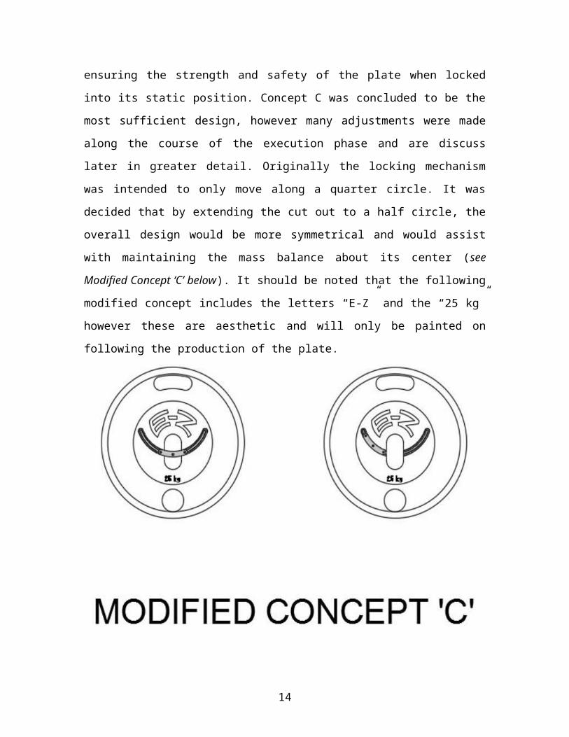
its static position. Concept C was concluded to be the most sufficient design, however
many adjustments were made along the course of the execution phase and are discuss
later in greater detail. Originally the locking mechanism was intended to only move along
a quarter circle. It was decided that by extending the cut out to a half circle, the overall
design would be more symmetrical and would assist with maintaining the mass balance
about its center (see Modified Concept ‘C’ below). It should be noted that the following
modified concept includes the letters “E-Z” and the “25 kg” however these are aesthetic
and will only be painted on following the production of the plate.
After making the necessary conclusions regarding Concept C, a meeting was scheduled
with the Senior Machinist and Design Technician at STFX, Steven Macdonald. Steven
provided the group with practical feedback with regards to material selections, feasibility
of construction for the locking mechanism and the possibility of constructing a model or
10

prototype for testing and presentation. The following recommendations were made
during the meeting:
I. Cast Iron should be used for the main construction of the plate, however;
II. Cast iron is a difficult metal to machine; therefore intricate or moving parts
should be constructed from another material that is easier to work with (ie.
Stainless Steel);
III. Before settling on a custom-made locking mechanism, consider making use of
available stock parts, namely the ‘hitch pin’ or ‘clevis pin’;
IV. Constructing a full size (25 kg) prototype may not be possible with the resources
available in the machine shop, instead;
V. Standard 10-lb plates could be modified to incorporate the proposed locking
mechanism on a smaller scale.
Following the meeting with Steven, Group 9 met to discuss the new information and
decide upon the best way to proceed. The discussion concluded that:
I. Cast iron is a commonly-used material for the construction of weightlifting plates
and would be well-suited for our project;
II. Using stainless steel in the locking mechanism would help reduce friction and
improve overall efficiency of the product;
III. The ‘hitch pin’ and ‘clevis pin’ suggested for review would be insufficient to
replace the locking mechanism currently proposed, but could possibly be
incorporated to work in conjunction with the proposed mechanism;
IV. A full size (25 kg) prototype is not necessary to complete the project
V. The 10-lb model will be sufficient to display and test the proposed locking
mechanism.
In conjunction with the 10-lb model which only accounts for implementation of the
locking mechanism, we rendered a 3-D model (see Appendix A) to display the work that
would be done on the actual standard plate if our design were to be carried out for
production. The plate design is discussed further later on in the report.
11

2.3 EXECUTION PHASEUpon completion of the planning phase, all of the necessary decisions had been made to
allow Group 9 to proceed into the execution phase. The execution phase has two main
components; producing a physical prototype, and completing the detailed design for The
E-Z Plate concept.
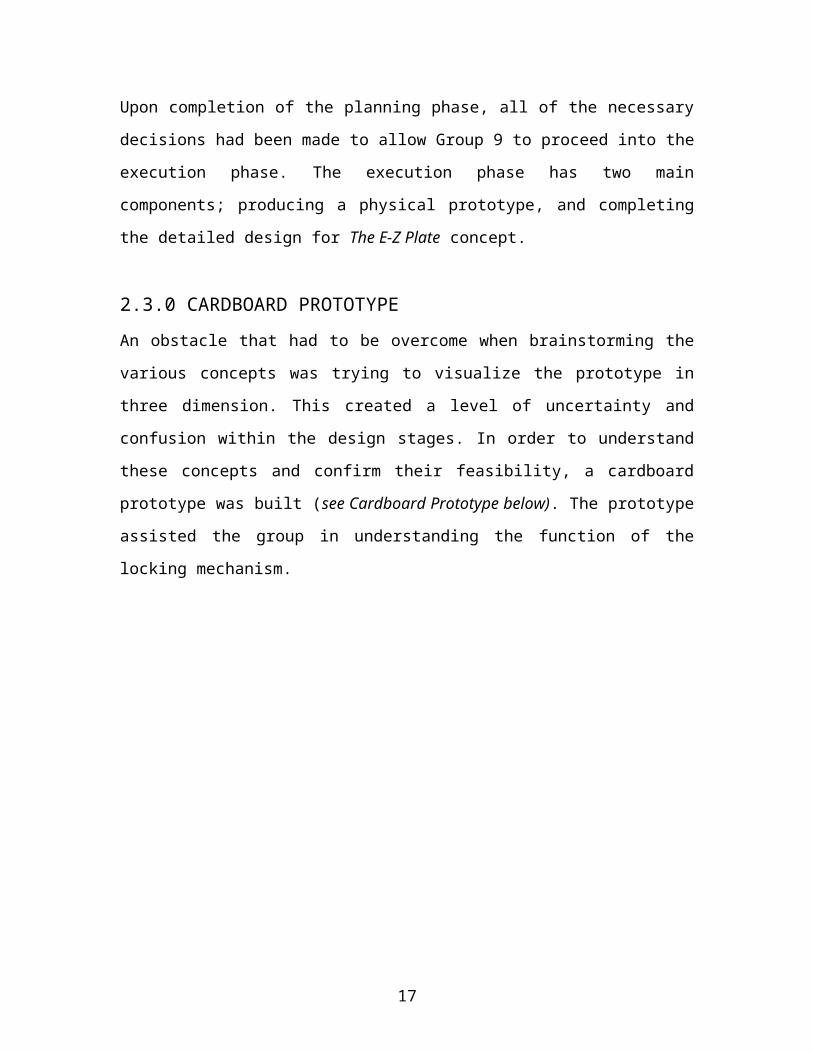
2.3.0 CARDBOARD PROTOTYPEAn obstacle that had to be overcome when brainstorming the various concepts was trying
to visualize the prototype in three dimension. This created a level of uncertainty and
confusion within the design stages. In order to understand these concepts and confirm
their feasibility, a cardboard prototype was built (see Cardboard Prototype below). The
prototype assisted the group in understanding the function of the locking mechanism.
Cardboard Prototype
12

2.3.1 MACHINING A PROTOTYPE Group 9 initially intended to produce a full-scale prototype to showcase the results of the
detailed design for the final presentation. However, after consultation with Steven
MacDonald, the purpose of the prototype was modified to simply demonstrate the
function of the proposed locking mechanism. Therefore correct dimensioning and
calculations were not necessary for the machining of the prototype. As a result, Group 9
was able to machine the prototype before center of mass calculations were done for the
full-size 25 kg plate. The resulting prototype features the designed locking mechanism
retrofitted into a standard 10 lb plate (see Machined Prototype below). The dimensions
used in the construction of the prototype were selected with the primary goal of creating
the best visual representation of the proposed locking mechanism, given that the
prototype is less than one quarter of the size of the 25 kg plate being designed. During
this stage, regular updates were made with Steven in order to address any concerns or
changes that needed to be made.
Machined Prototype
13
The first step in the construction of the 10 lb plate was to determine the dimensions for
the slots that Steven had to cut to allow for maneuvering of the locking mechanism.
Group 9 wanted to have the locking mechanism curved in order to dissipate the force
acting on the sliders over a greater surface area. It was important to make sure the
mechanism was not machined too tight in the plate because this would render it unable to
slide easily due to the friction between the collar of the bar and the sliders. After proper
dimensioning was done, Group 9 supplied Steven with the information needed to produce
the main cut out of the 10 lb plate. The curve cut out where the sliders would be guided
needed to have a large enough arc length so that when sliding the collar of the barbell
through the plate it would not prevent the locking mechanism from sliding into position.
It was originally planned to create the locking mechanism with three slider rods. After
consulting with Steven it was decided that two slider rods would be more efficient
because it reduced the friction in the locking mechanism and provided enough strength
on their own. However due to the size difference, this alteration was not continued with
the full size 25 kg plate. The largest change that occurred via consultation with Steven
was to have the slider rods extend the entire length between the sliders, instead of
welding them just on the outside. The reason for this decision was to reduce the amount
of parts needed to design the locking mechanism. Originally the final design would have
had three slider rods, two sliders, one handle and extra machining on one of the sliders. It
was decided to extend one of the slider rods through the slider to provide a handle on one
side. On the opposing side an indentation was made to allow for the plates to fit together
when stacked. This helped reduce the amount of parts needed in the locking mechanism
as well as the amount of machining that needed to be done. Another contribution Steven
had suggested and incorporated into the design of the locking mechanism was the peg
(see fig #). The peg is used to stop the slider mechanism from travelling the full length of
the half-circle cut out. Although the locking mechanism can only be maneuvered along a
quarter circle path, the full half-circle cut out creates symmetry and assists in helping
calculate the centre of mass. To machine a 90 degree edge is not feasible, and as shown
from the contrast between the machined plate and the cardboard plate our design evolved
from having hard corners to rounded ones (see Prototype Contrast on the next page).
14

Prototype Contrast
2.3.2 DESIGNING THE FINAL PROTOTYPEThe detailed design of the 25 kg plate consisted of determining dimensions and material
selections for each component to effectively support applied forces, have a total mass of
25 kg, and precisely locate the center of mass. In previous reports, moment of inertia was
mentioned as a property that would be considered during the detailed design. Upon
further review, it was determined that there is no true standard moment of inertia for
these plates, as plate models currently in use have wide variations geometry and mass
distribution. It was also mentioned previously that the full-size plate would be built to a
weight of 45 lbs. Since then, our research has indicated that Olympic and other high-
performance athletes lift standardized metric masses. It was then decided that our model
would be a 25 kg plate rather than the previously described 45 lb plate.
Weight Lifting standards list 450 mm and 53 mm (International Powerlifting Federation,
2015) as standard dimensions for the outer diameter of the plate and the diameter of the
center hole respectively. Aside from these two parameters, all other dimensions were to
be determined during the detailed design. This left far too many variables for analysis so
a few dimensions were chosen to facilitate ease of use and create the desired look and
feel. These dimensions were:
15

30 mm thickness for both the inner disk and the outer ring
5 mm thickness for each of the sliders
Gray ASTM 20 Cast Iron Alloy was material selected for the construction of the plate.
This material was chosen because it is a standard material for use in the construction of
weightlifting plates, and was also recommended during a consultation with Steven
MacDonald. The slider is fabricated from a number of small components that must be
precisely constructed and assembled. Steven (in the same consultation) suggested that
these pieces be built from a strong but workable metal, as cast iron is too brittle for such
small and precise components. Stainless 304 Steel Alloy was selected for use in the slider
components.
Since the most complicated geometry, including arc segments, are located in the center of
the plate, the first dimensions to be determined were the ones involved in the locking
mechanism.
The length of the slider was required to span the diameter of the center hole (53 mm)
with a reasonable overlap on either side of the center hole (approximately 10 mm). The
overlap region is necessary to support the forces applied to the slider.
To determine the size of the slider cross-section necessary to support the applied forces,
there were two main loading scenarios to consider (see Loading Scenarios on the next
page). The first involving the slider supporting the weight of the bar, under the force of
gravity. In this case, the mass of the bar (25 kg) is distributed over no less than 4 sliders
(one plate on either end of the bar, with two sliders on each plate). The maximum loading
scenario, however, occurs when the plate is lifted by the bar and rotates into an upside
down position, such that the plate’s mass (25 kg) is supported by the two sliders over the
bar. Both of these loading scenarios cause primarily shear forces in the slider. The ideal
method of analysis would have been to use the a shear stress calculation with the yielding
stress of the selected stainless steel material, with a factor of safety, to find the necessary
cross-section (and therefore height, given the 5 mm width). However, the material
16
properties listed in the back of the statics textbook did not include a value for the yielding
shear stress for the selected stainless steel material, so that analysis was not an option.
Loading Scenarios
Instead, Group 9 opted to use a beam deflection calculation, representing the slider as a
simply-supported beam with a 53 mm span, the weight due to the 25 kg mass equally
divided between the two endpoints and a single support in the middle of the beam.
Allowing a maximum deflection of 0.1 mm in the equation shown (see Deflection
Equation below), the height term within the moment of inertia expression (for the slider
cross-section) could be determined. This analysis revealed that the slider height had to be
only about 3 mm for the allowed deflection. However, this does not consider either shear
stress, or the functionality of the sliding mechanism. Since the slider component must be
fast and easy to grab and move, it was decided that a height of 15 mm (rather than 3 mm)
would be used. For assurance, the same applied force was run through the shear stress
equation (see Shear Stress Equation below) with the proposed slider cross-section. This
17

calculation returned a stress of about 1.6 MPa. While there was no listed shear yielding
stress for Stainless 304 Steel Alloy, the tensile and compressive yielding stress were 207
MPa. While it can’t be proven with certainty, the difference between the shear stress and
the tensile/compressive yielding stress provides a reasonable confidence in the strength of
the proposed cross-section.
Deflection Equation Shear Stress Equation
The remaining dimensions had to be determined such that the desired mass and centroid
could be achieved. AutoCAD and Microsoft Excel were used extensively in the
remaining portion of the analysis. The face of the plate was drawn out in AutoCAD with
dimensions being tentatively chosen based on the appearance of the plate. Each
geometric region on the face of the plate was listed on the Mass & Centroid Calculations
spreadsheet (see Appendix B.2). Each area was determined using AutoCAD’s “list”
command and entered in the spreadsheet. The corresponding thickness for each region
was entered in the next column, which allowed for calculation of the volume of each
region. The density of the material for each region was then listed in the next column
(negative densities were assigned to void spaces), which allowed for the calculation of
the mass of each region. A summation of each regional mass gave the total mass of the
plate, which would automatically update with any subsequent dimensional revisions. The
x- and y-coordinates for the centroid of each region were entered in the next two
columns. Most of these centroids were trivial to locate as the regions were circular or
simple composite shapes, however a number of regions were modelled as arc segments
which required manual centroid calculations using the formula listed in the Dynamics
textbook (Meriam, 2015). Products were then taken of the mass with each of the
18

individual x- and y-centroid locations. Sums of these products were taken for use in the
centroid formula (see Centroid Equation below) as given in the statics textbook
(Hibbeler, 2014). This formula was used to calculate the x- and y-coordinates of the total
center of mass. Lastly, three flexible parameters (thickness of the intermediate fill, radius
of the balancing circle, and the y-coordinate of the centroid of the balancing circle) were
adjusted using a trial-and-error method until the total mass reached 25.0000 kg and the
mass was centered with 0.0001 mm precision. This level of precision plays a significant
role in designing a high quality product, as was named as a major goal in this project.
Centroid Equation
A complete set of dimensioned and labelled orthographic and pictorial drawings for the
plate and locking mechanism (see Appendix A.3 & A.4) can be found in at the end of the
report.
2.4 CLOSING PHASEDuring the closing phase, the focus shifted to completing the necessary details in order to
present the final product. This included revising and formatting the AutoCAD drawings,
and using them to generate a 3D model to help display the final design. In this phase,
Group 9 decided to develop a logo to establish an identity and uniformity among works
(i.e. print, graphics, web, and presentations). The closing phase also included the
preparation of the final presentation.
3.0 PRODUCTION AND COSTThe industry norm for other high end weight plate companies like Eleiko and Ivanko is to
outsource and produce their cast iron plates in places like china where it can be achieved
19

at a much lower cost. In casting iron, the best way to do so is through the process of sand
casting. Sand casting is done by imprinting wet sand with the design and shape of your
desired product and pouring the molten iron into the casting. Some plates are currently
produced in the USA, however they are low quality and not for the target demographic
Group 9 is intending to sell to. With this in mind, Group 9 would aim to outsource in
producing the cast iron plate in order to keep up with our competition. From an
engineering company in China, a rough estimate for the pouring, finishing, packaging
and delivering of a 25 kg standard shape would cost around $50 Canadian (Cast Iron
Price Calculator, n.d.). These plates would then have to be shipped to Canada in order to
be assembled with the locking mechanism. In machining the sliders and slider rods, it
would be preferable to do so in Canada. Machining in large quantities can be done very
easily and based on industry standards for machining stainless steel, the cost for each
locking mechanism would be around 70 cents Canadian (CUSTOMPART.NET, 2009).
In order to assemble the locking mechanism onto the plate, labourers and welders would
be needed to finish the construction. Other companies selling high end and highly exact
weight plates sell at around the $250 price range and can go upwards of $325 per plate.
Because this plate will be breaking norm in the industry, Group 9 will look to sell the
plate at a relatively low profit margin in order to keep the costs down. Group 9 hopes to
produce The E-Z Plate at a cost of $60 for raw material production, casting and
machining, $100 for shipping and taxes and finally $20 for assembly, labour and welding
for a grand total of $180. At a 20% profit, The E-Z Plate would sell for $216 Canadian
and would be a very attractive option in the market due to the added ease of use, while
costing less than a plate that does not include the loading assistance that The E-Z Plate
provides. A large aspect of production that Group 9 will be tending to is the quality
assurance from the foundries that the cast iron is coming from. Group 9 will not accept
any imperfect plates produced, this includes look, size and weight, for this creates a large
concern in the fitness industry, where one can go to a gym and weigh a 20 kg plate only
to find it is actually 18 or 22 kg. This is what creates the market for the high quality and
exact plates that Group 9 will produce.
20

4.0 RECOMMENDATIONSA few recommendations should be considered if The E-Z Plate were to be produced for
the market. An efficient production system would need to be established to reduce the
cost of production and maximize profits. The E-Z Plate targets customers who will expect
the highest quality plates which are easy to use, durable, and precisely designed and built.
It is of the utmost importance that the quality of the plate is not compromised, as a result
of low-quality fabrication processes.
The design could also be incorporated into different types of weightlifting plates. There
are different types of cast iron and bumper plates used for specific exercises and
competitions. Powerlifting and Olympic Weightlifting plates are high quality plates that
are growing in popularity. Most of the exercises using these plates involve loading a
barbell on the ground, and could therefore benefit from implementing The E-Z Plate
design. No significant changes would have be made to the Powerlifting and Olympic
Weightlifting plates due to the simplicity of their design and geometry. Implementing the
mechanism developed for The E-Z Plate into other plate types would expend the market
and make The E-Z Plate solution available to a broader variety of athletes.
5.0 CONCLUSIONThe E-Z Plate design eliminates the deficiencies associated with loading and unloading
plates onto a barbell, resting on the ground. Although this report only includes the design
specifications for the standard 25 kilogram plate, the principles can be incorporated into
all standard sizes of weight lifting plates. It is expected to cost about $180 per unit to
produce The E-Z Plate commercially, which includes materials, shipping, casting,
machining and taxes. Group 9 plans to generate a 20% profit, resulting in a competitive
retail price of $216 for an easy to use and high quality plate.
This comprehensive design project came with a wide variety of responsibilities that
challenged our skills in various engineering courses including statics, strength of
materials, graphics and design. We were forced to think critically and apply the
21

knowledge and skills we have developed over the course of our studies at St. Francis
Xavier University to a real-life problem. It was rewarding to work as a team and
successfully engineer a solution to the deficiencies associated with loading and unloading
weight lifting plates, which the members of Group 9 felt needed to be addressed. In
summary, the goals initially established by Group 9 were to create a product that is easier
to use than the current standard plates on the market, is durable, and competitive in cost.
Group 9 has achieved these goals with the design of The E-Z Plate, as it has proven to
provide a more efficient loading process, can resist the stresses of weightlifting, and is
high in quality. Group 9 is proud to present this final edition of The E-Z Plate.
Electronic copies of this report and all previous works associated with The E-Z Plate
project are available on our website:
http://people.stfx.ca/engr/DesignProjects/2016/Group9/
22

References[1] Cast Iron Price Calculator. (n.d.). (DANDONG FUDING ENGINEERING MACHINERY
CO., LTD) Retrieved March 2016, from Dangdong Foundry: www.iron-foundry.com/cast-iron-price-calculator.html
[2] CUSTOMPART.NET. (2009). Retrieved March 2016, from Cost Estimator: www.custompertnet.com/estimate/machining/
[3] R.C. Hibbeler, Statics & Mechanics of Materials (Fourth Edition). Pearson Prentice Hall, 2014.
[4] J.L. Meriam, Engineering Mechanics Dynamics (Eighth Edition). John Wiley & Sons Inc., 2015.
[5] International Powerlifting Federation. (2015, December 10). Technical Rules.Retrieved from Inernational Powerlifting Federation: http://www.powerlifting-ipf.com/rules/technical-rules.html
[6] Lincir, T. (2001). National Fitness Trade Journal Magazine. The Making Of A Perfect Olympic Plate , 24-26.
23

Appendix AA.1
24

A.2
25

A.3
26

A.4
27

28

Appendix BB.1
29

B.2
30