transportation.ky.gov · web viewcontact derrick castle at the division of materials at least two...
TRANSCRIPT

Kentucky Transportation CabinetSIGN MANAGEMENT PROGRAM
User’s Guide
REVISION: NOVEMBER 2011

KYTC Sign Management Program User’s Guide
Table of Contents SMP-01
0 INDEXES01 TABLE OF CONTENTS...............................................................................................11/11
100 STOCKPILED SIGN INVENTORY101 INVENTORY PREPARATION......................................................................................11/11102 LOG-IN PROCESS (DESKTOP APPLICATION).............................................................11/11103 SIGN MANUFACTURE WINDOW FEATURES............................................................11/11
200 SYNC PROCEDURES201 LOG-IN/DOWNLOAD DATA PROCESS
(MOBILE APPLICATION)..............................................................................11/11300 ASSETS MANAGER (MOBILE APPLICATION)
301 ACCESSING ASSETS MANAGER ...............................................................................11/11302 ASSET MANAGER TOOLS.........................................................................................11/11303 ASSET MANAGER FUNCTIONS.................................................................................11/11
303-01 SEARCH FUNCTION.....................................................................................11/11303-02 THEME FUNCTION......................................................................................11/11303-03 SELECT FUNCTION......................................................................................11/11303-04 ZOOM FUNCTION.......................................................................................11/11
400 SIGN INSTALLATION PROCEDURES401 INSERTING A NEW ASSEMBLY.................................................................................11/11402 INSERTING A NEW SIGN FACE.................................................................................11/11
500 APPENDIX
11/11 Page 1 of 58

STOCKPILED SIGN INVENTORY
Inventory Preparation SMP-101
ORGANIZINGSIGN INVENTORY Arrange inventory in an orderly manner so that all like signs are stacked
together neatly. It may be good practice to rotate each sign so that the bottom right hand side of the sign is easily exposed for barcoding.
SPOT CHECKINSPECTION The Division of Materials will conduct an onsite spot check of existing sign shop
stockpiles before inventory. This inspection will include checking the validity of stockpiled sheeting types and retroreflectivity of existing signs. Contact Derrick Castle at the Division of Materials at least two weeks prior to the planned inventory start date to schedule the inspection.
BARCODEAPPLICATION Barcodes should be applied to the lower right quadrant of the back of the sign.
The lowest corner of the sign should be used for signs where the bottom edge of the sign is not parallel to the ground. The barcode should be placed no less than one inch and not more than three inches from the sign edges. (See Appendix)
When possible, barcodes should be applied to signs indoors at a temperature of 50 degrees Fahrenheit or higher. The application location should be clean (free of oils, dust, etc). If not clean, an alcohol swab should be used to clean the area then let dry before application. It may be best practice to clean several signs at a time so some dry while others are cleaned.
Keep barcodes in order especially within a particular type of sign if possible.
11/11 Page 2 of 58

STOCKPILED SIGN INVENTORY
Log-In Procedures (Desktop Application) SMP-102
LOG-INPROCEDURE
Login to OMSo Go to Resources>Materials>Inventory>Sign Manufacture
11/11 Page 3 of 58

STOCKPILED SIGN INVENTORY
Sign Manufacture Window Features SMP-103
OVERVIEW The Sign Manufacture Window is made up of two sub-windows Sign Attributes and Signs.
The Sign Attributes Sub-Window is used to enter sign data into the system tied to a specific barcode.
The Signs Sub-Window is used to display the sign manufacture history for the management unit accessed.
PROCEDURE
In the upper Sign Attributes Sub-Window, enter the required information into the Material Stock, Manufacturer, Date Manufactured, Sign Sheeting Type, Sign Color, and Sign Text columns.
Once all the sign information has been entered, click in the Barcode field and scan the barcode on the back of the first sign.
11/11 Page 4 of 58

STOCKPILED SIGN INVENTORY
Sign Manufacture Window Features SMP-103
PROCEDURE
(CONT.) Once ensured the Barcode field is populated from scan, click the Insert Like
button.
The newly inserted sign is now populated in the lower Signs Sub-Window and is added to the sign inventory.
Continue the scan-Insert Like process for every identical sign in inventory.
Repeat process for each like type of sign until entire inventory is barcoded and entered into the system.
11/11 Page 5 of 58

SYNC PROCEDURES
Log-in/Download Data Process (Mobile Application) SMP-201
LOG-IN PROCEDURE To capture the Sign Assembly and Face data for the locations where work will be
performed click on the Sync button.
11/11 Page 6 of 58

SYNC PROCEDURES
Log-in/Download Data Process (Mobile Application) SMP-201
LOG-IN PROCEDURE(CONT.) Enter User Name and Password information and click Sign In.
11/11 Page 7 of 58

SYNC PROCEDURES
Log-in/Download Data Process (Mobile Application) SMP-201
DOWNLOADPROCEDURE Select appropriate Department to work from and click on the Download button
at the bottom of page.
11/11 Page 8 of 58

SYNC PROCEDURES
Log-in/Download Data Process (Mobile Application) SMP-201
DOWNLOADPROCEDURE(CONT.) Select by checking the boxes next to the counties you intend to install signs.
This will download the most recent assembly and sign face information for the specific counties selected.
Notice the Delete Old Cache check box. This is used to de-select undesired counties that had been previously selected (un-checking the box will not accomplish this). Delete Old Cache will also remove any data that has not already been uploaded to the database. If there is assembly or sign face data for a county that is valid and not yet uploaded to the database it will be important to NOT check Delete Old Cache until the upload procedure has been completed successfully.
Once you have successfully downloaded the assembly and sign face data for the areas where work will be performed you will receive an “Operation Complete” pop up message indicating success. If you receive an error message then repeat the Download procedure. If errors persist contact the OMS helpdesk.
11/11 Page 9 of 58

SYNC PROCEDURES
Log-in/Download Data Process (Mobile Application) SMP-201
DOWNLOADPROCEDURE(CONT.) The previous steps will need to be repeated every time you will be working in an
area where updates to sign faces or assemblies have occurred since the last successful download.
At this point you have downloaded all the current assembly and sign face data for the areas where work will be performed and are now ready to
access the Asset Manager Software application for sign installation.
11/11 Page 10 of 58

ASSETS MANAGER (MOBILE APPLICATION)
Accessing Assets Manager SMP-301
ACCESSING ASSETS MANAGER Access the OMS mobile application and select Assets Manager to begin the sign
assembly and installation process.
After you have accessed the Assets Manager home page, ensure you have access to at least 3 GPS satellites as indicated in the upper left hand corner. If less than three satellites are accessed all assembly and sign face data will have to be inserted and selected manually.
11/11 Page 11 of 58

ASSETS MANAGER (MOBILE APPLICATION)
Asset Manager Tools SMP-302
OVERVIEW Upon entry into the Assets Manager software you will see 4 buttons on the left hand side of the screen. These following tools will enable you to accomplish several necessary functions for the sign installation process:
Settings
Zoom
Pan
Selection
11/11 Page 12 of 58

ASSETS MANAGER (MOBILE APPLICATION)
Asset Manager Functions SMP-303
OVERVIEW Each Asset Manager tool provides functions to help you navigate through the mobile application system. We will discuss the functions under the Settings tool:
Search
Theme
Select
Zoom
Asset
Rotate
Options
11/11 Page 13 of 58

ASSETS MANAGER (MOBILE APPLICATION)
Search Function SMP-303-01
SEARCH OVERVIEW Click on the Settings button to display all the available functionality. We will first discuss the Search function. By clicking on the Search function you can quickly search and retrieve sign face information by barcode.
11/11 Page 14 of 58

ASSETS MANAGER (MOBILE APPLICATION)
Search Function SMP-303-01
SEARCH OVERVIEW (CONT.) Enter the barcode number for the sign in question and click on Search.
11/11 Page 15 of 58

ASSETS MANAGER (MOBILE APPLICATION)
Search Function SMP-303-01
SEARCH OVERVIEW(CONT.) You will be directed to the form view of the Sign Faces screen and all sign face
information for the barcode entered is displayed and is now available for edit.
By holding the stylus on the screen you enable additional options for update.
11/11 Page 16 of 58

ASSETS MANAGER (MOBILE APPLICATION)
Search Function SMP-303-01
INSERT OPTION
The Insert option enables you to quickly insert a new sign face to the same assembly as the sign the barcode search was performed above. After clicking insert you will see the screen below. Enter in all the necessary information for the new face being applied (Barcode, Status, Comments, etc.). Install date will auto default to today’s date.
11/11 Page 17 of 58

ASSETS MANAGER (MOBILE APPLICATION)
Search Function SMP-303-01
INSERT OPTION(CONT.)
Once you have successfully entered in all necessary information click Save to accept the changes into the system.
11/11 Page 18 of 58

ASSETS MANAGER (MOBILE APPLICATION)
Search Function SMP-303-01
INSERT OPTION(CONT.)
NOTE: Gives ERROR message. This option is currently not functional.
11/11 Page 19 of 58

ASSETS MANAGER (MOBILE APPLICATION)
Theme Function SMP-303-02
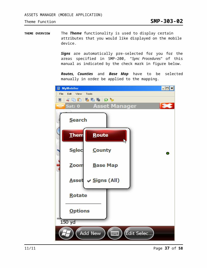
THEME OVERVIEW The Theme functionality is used to display certain attributes that you would like displayed on the mobile device.
Signs are automatically pre-selected for you for the areas specified in SMP-200, “Sync Procedures” of this manual as indicated by the check mark in figure below.
Routes, Counties and Base Map have to be selected manually in order be applied to the mapping.
11/11 Page 20 of 58

ASSETS MANAGER (MOBILE APPLICATION)
Theme Function SMP-303-02
ROUTE OPTION By selecting Route from the Settings>Themes>Route option you will see the routes displayed.
11/11 Page 21 of 58

ASSETS MANAGER (MOBILE APPLICATION)
Theme Function SMP-303-02
COUNTY OPTION In order to view county names and boundaries click on Settings>Theme>County.
11/11 Page 22 of 58

ASSETS MANAGER (MOBILE APPLICATION)
Theme Function SMP-303-02
BASE MAPOPTION By clicking Settings>Theme>Base Map you activate all the additional features
including route names, major route outlines, creeks, ponds and local mapping features.
Generally, you can maneuver sufficiently with just the Signs and Base Map turned on. Rural areas may require the Route be turned on in some instances.
11/11 Page 23 of 58

ASSETS MANAGER (MOBILE APPLICATION)
Select Function SMP-303-03
SELECT OVERVIEW The Select functionality gives you several options for selecting assemblies for sign edit or installation. Once an assembly has been successfully selected the Edit Selection button at the bottom of the page will enable to you to update selected assemblies and sign face data accordingly.
The different options for selecting sign assemblies are outlined below.
11/11 Page 24 of 58

ASSETS MANAGER (MOBILE APPLICATION)
Select Function SMP-303-03
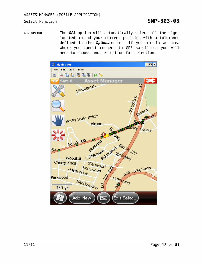
GPS OPTION The GPS option will automatically select all the signs located around your current position with a tolerance defined in the Options menu. If you are in an area where you cannot connect to GPS satellites you will need to choose another option for selection.
Once the GPS has located all the signs within the tolerance of the current position you will notice the assemblies flash from green to yellow indicating that they were selected by GPS.
Once one or more assemblies have been selected (displays yellow) you can click on the Edit Selection option to update the assembly and sign information.
11/11 Page 25 of 58

ASSETS MANAGER (MOBILE APPLICATION)
Select Function SMP-303-03
POINT OPTION The Point feature is the auto selected default selection tool upon entry into the Asset Manager software. It will enable the user to select all the assemblies that lie within the tolerance of where they click the stylus on the mapping (where GPS selected assemblies around the current device location).
Once the user clicks on the mapping the signs that lie within the tolerance of the click will flash from green to yellow meaning they are selected. At this point the user can click on the Edit Selection button to update assembly sign information.
RECTANGLE OPTION The Rectangle selection feature enables the user to draw a rectangle around the assemblies in question in order to select them for update.
This is accomplished by selecting Settings>Select>Rectangle then clicking the stylus on the mapping and dragging a rectangle completely around the assemblies needed for update (keep stylus on the screen of the device until satisfied with position, lifting will close the rectangle). Upon successful selection, the assembly indicator will flash from green to yellow indicating updates are available using the Edit Selection tool.
11/11 Page 26 of 58

ASSETS MANAGER (MOBILE APPLICATION)
Select Function SMP-303-03
POLYGON OPTION The Polygon selection tool enables the user to draw a fence completely around the assemblies needed for update.
To activate this selection feature go to Settings>Select>Polygon and tap the stylus no more than three times in locations to completely enclose the assembly for update. Once successfully selected the assembly indicator will flash from green to yellow.
Note: Currently tapping the stylus around the assembly indicator more than three times bugs the selection tool and makes selecting difficult. We are working to improve this feature.
11/11 Page 27 of 58

ASSETS MANAGER (MOBILE APPLICATION)
Select Function SMP-303-03
SATELLITE SIGNALINDICATOR OPTION We will discuss the Zoom functionality below but there is also a zoom function
that is not listed in the toolbar but is a very useful tool and is worth discussing. If the user clicks on the orange satellite signal indicator, the user’s exact location will be automatically jumped to at a very workable scale. This function will only work when the user has access to a minimum of three satellites but dramatically improves the ability to quickly locate the device on the map.
11/11 Page 28 of 58

ASSETS MANAGER (MOBILE APPLICATION)
Zoom Function SMP-303-04
ZOOM OVERVIEW The Zoom functionality located in the Settings>Zoom toolbar enables the user to choose different methods to view the mapping and assembly data at different scales.
11/11 Page 29 of 58

ASSETS MANAGER (MOBILE APPLICATION)
Zoom Function SMP-303-04
IN-OUT OPTION The Settings>Zoom>In-Out function is automatically pre selected for the user upon entry into the Asset Manager screen and is enabled by tapping the stylus on the screen and dragging up to zoom in and dragging down to zoom out. Depending on how far the user drags the stylus either up or down will define how far the zooming into or out of the map will occur.
IN OPTION The Settings>Zoom>In functionality is enabled by tapping and dragging the stylus around the area the user wants to view at a smaller scale. Notice there is a large black rectangle with some areas grayed out while the smaller rectangle inside is clear. The clear rectangle will be the area that you will zoom toward once you release the stylus from the screen.
11/11 Page 30 of 58

ASSETS MANAGER (MOBILE APPLICATION)
Zoom Function SMP-303-04
OUT OPTION The Settings>Zoom>Out functionality is enabled by tapping and dragging the stylus around the area the user wants to view at a larger scale. Notice there is a large black rectangle with some areas grayed out while the smaller rectangle inside is clear. The clear rectangle will be the area that you will zoom out around once you release the stylus from the screen. Depending on how far you drag will determine how far you zoom out around that clear area.
11/11 Page 31 of 58

ASSETS MANAGER (MOBILE APPLICATION)
Zoom Function SMP-303-04
FULL EXTENTOPTION The Settings>Zoom>Full Extent function enables the user to quickly zoom all the
way out to get a full view of the state. This is useful if you have lost your current location and want to start the zoom process over.
11/11 Page 32 of 58

ASSETS MANAGER (MOBILE APPLICATION)
Zoom Function SMP-303-04
DEFAULT EXTENTOPTION The Settings>Zoom>Default Extent will enable the user to define a particular
view of a mapping location at a defined scale and automatically zoom into that location with the defined settings. This is a very useful zoom tool for users and would recommend that it is defined from your starting location. By immediately selecting this zoom feature you will always zoom right into your starting location at a workable scale simplifying the daily zoom to locate your assemblies.
Note: The default extent location and scale is defined in the Settings>Options toolbar and clicking the Set currently visible extent as default check box when your current extent is where you would like to save for future use.
11/11 Page 33 of 58

SIGN INSTALLATION PROCEDURES
Inserting a New Assembly SMP-401
OVERVIEW There are two ways to add an assembly into the database. One of those ways is to insert using GPS and the other is manually.
ADD NEW ASSEMBLYUSING GPS In order to insert a sign using the GPS functionality you will need a clear line of
sight to the sky with access to at least three satellites. You can check how many satellites you have access to by looking in the upper left hand corner of the screen for your current satellite connection as shown below.
Once GPS connection is established move to the location where the assembly is to be installed and select Add New at the bottom of the screen.
Note: An assembly will be inserted onto the mapping in the exact location of the device when the Add New button is clicked. It is important that the device be at the exact location the assembly is to be installed when Add New is selected.
11/11 Page 34 of 58

SIGN INSTALLATION PROCEDURES
Inserting a New Assembly SMP-401
ADD NEW ASSEMBLYUSING GPS(CONT.)
11/11 Page 35 of 58

SIGN INSTALLATION PROCEDURES
Inserting a New Assembly SMP-401
EDITING ASSEMBLYLOCATION DETAILS Once Add New is selected, an assembly form view pop up window will be
displayed in order for the user to insert the details of the assembly installation.
SAVING ASSEMBLYLOCATION DETAILS Once the necessary information has been inserted click the Save button at the
bottom of the screen. The user will be prompted with a Save Edits pop up box indicating the successful changes, click OK then Back (at the bottom of the screen) to be redirected to the mapping screen.
11/11 Page 36 of 58
SIGN INSTALLATION PROCEDURES
Inserting a New Assembly SMP-401
SAVING ASSEMBLYLOCATION DETAILS(CONT.)
The user will now see a green assembly indicator for the exact location of the device at insert (if user leaves the site to finalize the form view device will install based on location of device when Add New was selected).
11/11 Page 37 of 58
SIGN INSTALLATION PROCEDURES
Inserting a New Assembly SMP-401
SAVING ASSEMBLYLOCATION DETAILS(CONT.)
11/11 Page 38 of 58
SIGN INSTALLATION PROCEDURES
Inserting a New Assembly SMP-401
ADD NEWASSEMBLYMANUALLY There will be times when the user will be unable to obtain access to the
necessary amount of GPS satellites and in these instances the user will be forced to insert new assemblies using the manual insert option.
In order to insert an assembly manually, click on the Add New button at the bottom of the Asset Manager home screen. You will be prompted with an error message that there are not enough visible satellites. Click “Yes” when asked, “Would you like to use manual insert instead?”
The user will be redirected to the mapping screen and given the ability to insert an assembly wherever the stylus is clicked on the screen. The location for insert is defined by a red box when selected.
Note: If the user feels they did not click in the exact location of the assembly just click again. The assembly will insert at the last location selected prior to clicking Edit Selection as indicated by location of red box.
11/11 Page 39 of 58

SIGN INSTALLATION PROCEDURES
Inserting a New Assembly SMP-401
ADD NEWASSEMBLYMANUALLY(CONT.)
11/11 Page 40 of 58

SIGN INSTALLATION PROCEDURES
Inserting a New Assembly SMP-401
ADD NEWASSEMBLYMANUALLY(CONT.) Once the user is satisfied with the location for insert, click on the Edit Selection
button. The user will be taken to the assembly form view pop up window in order for the user to insert the details of the assembly installation.
Once the necessary information has been inserted click the Save button at the bottom of the screen. The user will be prompted with a Save Edits pop up box indicating the successful changes, click OK then Back to return to the mapping screen.
11/11 Page 41 of 58

SIGN INSTALLATION PROCEDURES
Inserting a New Assembly SMP-401
ADD NEWASSEMBLYMANUALLY(CONT.)
11/11 Page 42 of 58

SIGN INSTALLATION PROCEDURES
Inserting a New Sign Face SMP-402
ADD NEWSIGN FACE In order for the user to insert a new sign to an assembly or edit an existing sign
record, the assembly for the sign in question must be selected.
Once the appropriate assembly has been selected (indicated by flashing from green to yellow) click on the Edit Selection button at the bottom of the screen. The user will be directed to the Assembly Location details window. By placing and holding the stylus on the screen a pop up window will be displayed with sign face and assembly options.
11/11 Page 43 of 58

SIGN INSTALLATION PROCEDURES
Inserting a New Sign Face SMP-402
ADD NEWSIGN FACE(CONT.)
Insert - By selecting Insert the user will be directed to another Assembly Location pop up window to insert a new assembly at the same location of the selected assembly.
Insert Like - The Insert Like function will insert an assembly in the same location as the assembly selected with similar characteristics.
Delete - Delete is how the user deletes the Assembly selected.
Form View - Form View will return the user back to the Assembly Location screen to edit assembly characteristics.
Sign Faces - The Sign Faces selection enables the user to insert and edit specific sign information for the assembly selected.
Once the user selects Sign Faces they will be directed to a window listing all the existing sign faces attached to the assembly selected.
11/11 Page 44 of 58

SIGN INSTALLATION PROCEDURES
Inserting a New Sign Face SMP-402
ADD NEWSIGN FACE(CONT.) Once the user has accessed the Sign Faces screen by tapping the stylus on the
screen and holding a pop up window will display showing available options to update the sign face data. We will discuss the Insert functionality.
Insert - Insert will insert a new sign face to the existing assembly. Once the new record has been inserted, enter in the appropriate Barcode, Status, Damage and Comments information. Install date is auto populated to current date.
Once complete with all the new sign face data click the Save button at the bottom of the page to save the changes.
NOTE: The ability to Delete a sign face still doesn’t seem to be functioning so (for the pilot) if you happen to insert a sign incorrectly, do not save for now. We apologize for the inconvenience but this functionality was missed during the testing phase of the software development. We expect an update soon for some of the issues already outlined in this manual.
11/11 Page 45 of 58

APPENDIX

APPENDIX
Appendix A-1 SMP-501
11/11 Page 47 of 58
APPENDIX
Appendix A-1 SMP-501
11/11 Page 48 of 58

APPENDIX
Appendix A-1 SMP-501
11/11 Page 49 of 58

APPENDIX
Appendix A-2 SMP-502
11/11 Page 50 of 58

APPENDIX
Appendix A-3 SMP-503
11/11 Page 51 of 58

APPENDIX
Appendix B-1 SMP-504
Approved Products
11/11 Page 52 of 58

APPENDIX
Appendix B-1 SMP-504
11/11 Page 53 of 58

APPENDIX
Appendix B-1 SMP-504
11/11 Page 54 of 58

APPENDIX
Appendix B-1 SMP-504
11/11 Page 55 of 58

APPENDIX
Appendix C-1 SMP-505
TroubleshootingGPS
Often you will find yourself outside of GPS range and get a pop up error when clicking on “Add New” that says:
This is acceptable, just select “Yes” and insert the new assembly manually.
You may also receive this same error when you are sure you are in GPS range but the GPS did not start up properly. In this case click on the GPS
icon in the upper left hand part of the screen to attempt to re-activate the GPS functionality.
11/11 Page 56 of 58

APPENDIX
Appendix C-1 SMP-505
ERROR LOG FILE
If you are getting an error with the software that you cannot figure out and contact the OMS helpdesk for assistance, the helpdesk will often request you send the log file from the device. Below is an outline on how to obtain the log file:
1. First go to Active Sync and click on Explore
2. Next double click to open “My Windows Mobile-Based Device” to view a list of files on the mobile device.
11/11 Page 57 of 58

APPENDIX
Appendix C-1 SMP-505
ERROR LOG FILE(CONT.)
3. Finally locate the .log file, save it to your computer and email it to the person requesting the file.
11/11 Page 58 of 58