proceedingsedge.rit.edu/content/p11212/public/finalpaper.docx · web viewdue to the development...
TRANSCRIPT

Multi-Disciplinary Senior Design ConferenceKate Gleason College of Engineering
Rochester Institute of TechnologyRochester, New York 14623
Project Number: 11212
LAND VECHILE FOR EDUCATION: CONTROLS AND RF
Nicholas Giudice (EE) Gohkan Karahan (EE)
Dan Sirgey (CE)
Copyright © 2011 Rochester Institute of Technology

Proceedings of the Multi-Disciplinary Senior Design Conference Page 2
ABSTRACT
Technology in the robotics field has expanded vastly over the century and has caused great advancement in economic growth. In today’s society many projects revolve around this idea of robotics and depend greatly on its functionality. Each component of the robot must be working correctly at all times, if one subsystem goes down the rest will follow.
A majority of robots are used to perform precise objectives determined from a user. In order for these robots to accomplish these tasks a control system is needed. These control systems can range from open loop (H-bridges), closed loop (PID and sensors), feed forward loop, and adaptive control. Each system has a unique way of approaching a task, some maybe more efficient than others.
In order for the control system to be effective, an accurate communication link must be in place. Over the years RF has lead the field of communications, due to fact that many applications rely on UAV and non-line-of-sight. In addition, RF communications allocates numerous channels of operation allowing simultaneous functionality, which is a necessity for P11212. With this scheme in place an Open-source Open Architecture command will be implemented.
A chassis is needed to hold all the components together without causing interference with one another. Also, it must allocate proper power distribution among each system. The chassis acts like a home, it must be robust enough to handle any hardships that might encounter and protect all of the vital internal equipment from dust, moisture, and tampering.
NOMENCLATURE
DC – Direct Current
EMF – Electromagnetic FieldGUI – Graphical User InterfaceIC – Integrated CircuitI/O – Input OutputLV-1 – Land Vehicle 1 kgLVE – Land Vehicle for EducationMC – Motor ControllerMSA – Modular Student AttachmentOhm – Unit of resistancePCB – Printed Circuit BoardPWM – Pulse Width ModulationRF – Radio FrequencySMT – Surface Mount TechnologyV – Volt, a unit of electrical chargeWOCCS – Wireless Open-Source/Open-Architecture Command & Control System
INTRODUCTION AND BACKGROUND
The Rochester Institute of Technology is going through tremendous amount of changes in the years to come. In 2013 a full change in academic structure will occur, switching from the quarter system over to the semester system. This will cause classroom lectures and labs to be taught over a longer time period. In order to accommodate the difference in time, new projects and material must be added to the curriculum. The object of P11212 is to fill in this time gap for first year mechanical engineers. This project will create a hand on experience allowing the students to control a land vehicle wirelessly. Also, students will design a mechanical structure on top of the land vehicle, MSA which also has a control system. This structure can range from a crane, catapult, anything the teacher requires the students to make that will enhance their knowledge about mechanical engineering
PROCESS
Needs and SpecificationsStarting from a single conversation with the customer, it is often hard to get a true idea of what they are looking for. From this intuition
Project P11212

you have from these initial conversations stem the entirety of the design, so formalizing them in some way is best for everyone. This formalization takes the form of customer needs and engineering specifications. The needs are what you gain from the customer, the general ideas of the duties the product is to perform. From these needs the specifications are designed, the testable metrics.
Specifically for our project, there was a dual layer of specifications. Due to the project layout, there was a layer for the goals of the project as a whole, and those for each of the sub-systems.
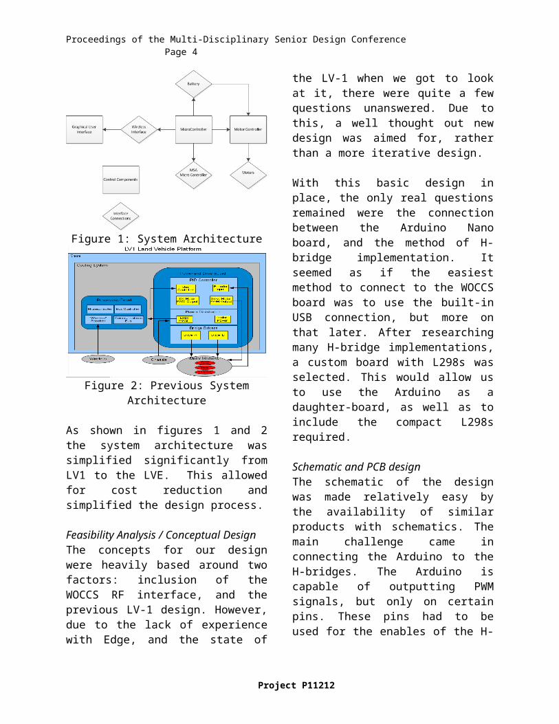
Figure 1: System Architecture
Figure 2: Previous System Architecture
As shown in figures 1 and 2 the system architecture was simplified significantly from LV1 to the LVE. This allowed for cost reduction and simplified the design process.
Feasibility Analysis / Conceptual DesignThe concepts for our design were heavily based around two factors: inclusion of the WOCCS RF interface, and the previous LV-1 design. However, due to the lack of experience with Edge, and the state of the LV-1 when we got to look at it, there were quite a few questions unanswered. Due to this, a well thought out new design was aimed for, rather than a more iterative design.
With this basic design in place, the only real questions remained were the connection between the Arduino Nano board, and the method of H-bridge implementation. It seemed as if the easiest method to connect to the WOCCS board was to use the built-in USB connection, but more on that later. After researching many H-bridge implementations, a custom board with L298s was selected. This would allow us to use the Arduino as a daughter-board, as well as to include the compact L298s required.
Schematic and PCB designThe schematic of the design was made relatively easy by the availability of similar products with schematics. The main challenge came in connecting the Arduino to the H-bridges. The Arduino is capable of outputting PWM signals, but only on certain pins. These pins had to be used for the enables of the H-bridges, which allows for speed control.
Proceedings of the Multi-Disciplinary Senior Design Conference Page 4
Some other issues were protecting the various components on the board. With motors, there is often a large EMF generated. This produces noise on the various signals around the motors. To protect the components from this, two steps were taken. First, to prevent input voltage noise, capacitors were placed at the inputs of components and the board to filter out the high-frequency noise present. Ideally, this leaves just the DC voltage required. The other step taken was to enclose the WOCCS board within a metal shield, to prevent interference with the RF communications.
Finally, a last issue with the motors was a possibility of current being driven back into the MC board. This was solved by adding diodes to the outputs. This way, if current is driven into the board by the motors, it is routed away from the L298s, protecting them.
The layout of the PCB was simplified quite a lot by the decision to go with a single IC H-
bridge. This limited the number of components that had to be placed on the board. However, a challenge was the ideal size of the boards. This did not allow for much space, and with three rather large components on the board, namely the L298s and the Arduino Nano, organizing everything in a way that made sense took some work. The design was done multiple times, each approaching a functional design slowly. Help from other teams was also used to best design the board.
Figure 3: PCB layout
Project P11212
Figure 4: PCB Schematic

Board AssemblyAssembling the board was a relatively simple task, apart from the SMT components. The SMT lab on campus provided a great place to put these tiny components onto the PCB. The through-hole components were also placed on the board in this lab. The main issue in putting everything together was a lack of clamps. For the SMT components this is not so much a problem, but the L298s were very difficult to attach alone. Due to this, all the through-hole components were connected by two people, one to hold the components and one to do the soldering.
Figure 5: Assembled Board
Software DevelopmentFirst of all, the previous LV-1 program was investigated. After looking over the interface even briefly, it became clear that this program would not suit our needs. It seemed to be designed for testing, not for use by the end user. It also would have required extensive redesign in order to incorporate the MSA functionality. To this end, a complete redesign was in order.
Due to the development using the Arduino platform, it made the most sense to centralize the programming around the Processing language. The Arduino language is a slight deviation from Processing, using a few new keywords to handle the hardware commands required by the Arduino. Processing itself is derived from Java, which allows for many GUI elements to be done quickly and easily.
However, it also provides some challenges, as the Processing language lacks strong GUI libraries for its main window. After looking at the available libraries, the ControlP5 library was chosen for its clean style and relatively high amount of customization.
Figure 7: Main GUI Window
Another issue was the control scheme for the LVE. With input from the other teams, a differential drive scheme was decided on, with a Logitech Dual Action joypad. Integrating this into Processing also required looking into some libraries. At first, no suitable one was discovered, and some testing was done to integrate a C library into a custom Processing library. This proved slightly difficult, but would have been possible. However, a library was discovered which already existed and accomplished all our goals.

Proceedings of the Multi-Disciplinary Senior Design Conference Page 6
Figure 8: Control Settings Window
For actually designing the GUI program, a rough class diagram was drawn up. However, it missed a lot of preconceived needs and design decisions, and required updating. The programming itself went relatively smoothly, with a few issues surrounding the joypad customization and MSA GUI options.
Designing the Arduino program was even simpler. The basis of the Arduino is I/O, which is input from the WOCCS board and output to either the MC board or the MSA. It can simply wait until there is data coming into it, and then make a decision based on an instruction ID at the beginning of the message. At this point the Arduino code is relatively minimal, but could become much more complicated if sensors or autonomy were included.
Testing and DebuggingTesting of the design proved generally successful, with a few small issues. The first was a problem discovered with the PCB itself. Once assembled, power and control signals were provided to test the voltage output of the MC board. While one H-bridge was operating successfully, one of the outputs from the other was a constant 7.2V. It turned out that one of the through-hole connections for the fuse was connected to the 7.2V power plane, causing the observed output. This was remedied by scratching away the copper layer of the board between
the through-hole and the power plane. It should be noted that this problem was not present on the other board. Therefore, the solution for the future is to increase the tolerances between the through-holes and power/ground planes on the PCB redesign.
Another problem was encountered when integration testing was performed. Even though the H-bridges were receiving the correct signals from the Arduino, the motors were still not turning, and in fact the outputs of the MC board appeared to be the brake condition. However, after looking over everything on the board, it was discovered that some of the resistors were sized incorrectly. What was supposed to be a small 0.5Ohm resistor to allow for managing the voltage was instead a 100kOhm resistor. This prevented current from flowing through the H-bridge, which in turn caused the effects as observed. By replacing the resistors with a small piece of wire, the functionality of the board was corrected, and the motors were driven as designed.
Once all the debugging issues were taken care of formal tested was started. From the testing it was determined that the LVE Controls met the majority of the design specs. The major tests run was temperature testing. Start up time required to operate the LVE. Control range of the LVE and finally bandwidth. There were also a number of less formal tests done for observational specs.
Temperature testing revealed that after extensive use of the LVE no point on the control board exceeded 45 degrees C which was well within operating range for all components on the board. Our start up testing revealed that the LVE can be used in under 30 seconds of startup time allowing the students the ability to quickly modify or change the LVE without having to wait long periods of time to use it again. The operational range of the LVE is a spec that
Project P11212

was not met. Through testing we were only able to achieve a control range of 150 feet. This is well below the target of 200 meters. This may be due to the way that the RF board was powered since it was drawing power from a laptop USB port rather than an independent power supply. Besides the control range all other tests were passed with a healthy margin of safety.
RESULTS AND DISCUSSION
A rigorous testing structure was used in order to test both the software and hardware of the LVE controls system. Each individual component of the controls was tested independently before running a full system evaluation. Once the controller functionality was confirmed in a lab environment, interface testing was performed with other teams of the LVE project.
In subsystem testing, we found a number of small design errors that had to be reworked and corrected. In addition we found that the board preformed as expected and met the requirements for the project in a general sense.
Continuing down the circuitry of the controller, we tested the functionality of the motor drivers. After powering up the board, we simulated the functionality of the LVE and the RF by using a power supply and a controller. The outputs for the DC motors were then monitored using a multimeter. The observed voltages at the input to the motor modules were exactly what we expected. The outputs of the H-bridges had a higher floating voltage than expected but it did not affect performance. The functionality of the PWM on the Arduino Nano was also tested by using a breadboard as well as a number of LEDs to see the variable voltages going through them which led to varying intensity of the LEDs. The functionality of the FWD/REV signal from the motor controller
was also confirmed by plugging this pin to ground for Forward and to the PWM signal for Reverse.
In order to examine the software of the LVE, we programmed the Arduino Nano and the WOCCS. Since we decided create all original code due to a change in the control system there was quite a bit of work done in this area. The first thing that had to be accomplished was interfacing the WOCCS board with the Arduino Nano and getting them to communicate properly. After that was done it was required to develop a GUI and
Additional testing of the controller required one or more of the other LVE projects in order to evaluate how well it could interface. The first testing was performed with the chassis team. By switching out the multimeter probes from our previous testing with a DC motor, we were able to confirm the forward and reverse motion of the traction motors as well as speed modifications using the adjustable duty cycle on the waveform generator. This testing was done with both the RF as well as the controller hooked up.
CONCLUSIONS
The 1st generation LV1 motor controller had improved upon the previous generation RP1 motor controller (designed by P09204 in 2009) in many ways. Our motor controller took that one step further. By simplifying and reducing overall area of the LVE controls we were able to reduce cost drastically while still retaining functionality of the LVE. Many elements of the previous controls were removed such as the PID controller. In addition the H-bridges used in the LVE control are a smaller and more compact IC rather than using discrete transistors to accomplish the same goal

Proceedings of the Multi-Disciplinary Senior Design Conference Page 8
Our controller also eliminates the need for a separate logic power source. Previously, in the RP1, there were two different voltage sources used to power individual elements of the controller. The LVE design is constructed to handle a single power supply and regulate it to levels required by all of the controller subsystems. This feature is important because it saves space and increases controller usability.
Perhaps the most important feature of our controller design is that is cuts down on the overall cost to manufacture a single unit by 80% from the LV1. This value increases with the number of units manufactured since many of the controller components are cheaper when ordered in bulk.
As changes are made to the other components of the LVE platform, there may be a need to alter some of the controller design. If sensors are included the PCB will have to be altered to pin out additional ports on the daughter card. If the motors are changed the sizes of the H-Bridges and possibly types of Diodes may need to be altered.
RECOMMENDATIONS
Future teams should closely examine all aspects of the current design. Major cost reduction can be found in a cheaper RF solution or a cheaper daughter card or microcontroller. Another thing to consider is reducing the overall space of PCB in the design. The MSA controls and Chassis
controls can be integrated onto a single PCB, and perhaps a single microcontroller, reducing redundancy as well as making interfacing easier. Since such a large cost of the project is the RF an off the shelf solution should be seriously considered.
Other ways to improve functionality of the LVE is possibly upgrade the H-bridges to a model with more effective over-current protection or better heat dissipation, or to design and add custom over-current protection circuitry. Finally there is a need for a voltage shifter or regulator to handle the communication between the control board and the RF solution.
ACKNOWLEDGMENTS
Special thanks goes out to all of the Kate Gleason College of Engineering Faculty and Staff that contributed to the design of the Controls. In addition the support of the staff in the SMT lab was essential to the construction and assembly of the Control system. We would also like to thank our Sponsor Dr. Edward Hensel for his time and his insight on the scope of the project. The team would also like to thank the Mechanical Engineering Department for their financial contributions and academic support. Finally, we would also like to thank our guides Phil, Leo and Vince for their direction and advice throughout the project. Without them we would not have been able to get here.
Project P11212