viewing oct8 f17 -...
TRANSCRIPT
CS464 Oct 3rd 2017
Assignment 3 – Due 10/6/2017Due 10/8/2017
Implementation Outline

Assignment 3 Skeleton
A good sequence to implement the program1. Start with a flat terrain sitting at Y=0 and Cam at Y=0.52. Add in code to compute a View Matrix 3. Add in Mouse Code to handle looking around.4. Add in Mouse Code to let you drive around.5. Adjust the terrain to vary Y but keep values between 0
and 0.3 – so no big leaps.6. Add code to extract Height from Texture object7. Adjust Cam height with height from texture object.8. Adjust Cam view angle to vary with terrain.9. Adjust Cam up angle to vary with terrain.

Could we use Vertex ShaderIdeas for how we might use the vertex shader?

Viewing
COMPSCI 464
Image Credits: Encarta and http://www.sackville.ednet.ns.ca/art/grade10/drawing/perspective4.html

Graphics Pipeline• Graphics hardware employs a sequence of
coordinate systems– The location of the geometry is expressed in each
coordinate system in turn, and modified along theway
– The movement of geometry through these spacesis considered a pipeline
Local Coordinate
Space
World Coordinate
SpaceView Space
Canonical View
Volume
Window/ Screen Space

Standard Sequence of Transforms
Image credits: http://www.cs.cornell.edu/courses/cs4620/2009fa/lectures/10viewing.pdf

Canonical View Volume} CanonicalView Space:A cube,with the origin at the center,
the viewer looking down –z,x to the right,and y up} CanonicalViewVolume is the cube:[-1,1]×[-1,1]×[-1,1]} Variants (later) with viewer looking down +z and z from 0-1} Only things that end up inside the canonical volume can appear in the
window

Canonical View Volume} Tasks: Parallel sides and unit dimensions make many
operations easier} Clipping – decide what is in the window} Rasterization - decide which pixels are covered} Hidden surface removal - decide what is in front} Shading - decide what color things are

Window/Screen Space} Window Space:Origin in one corner of the“window” on
the screen, x and y match screen x andy
} Windows appear somewhere on the screen} Typically you want the thing you are drawing to appear in your window} But you may have no control over where the window appears
} You want to be able to work in a standard coordinate system– your code should not depend on where the window is
} You target Window Space,and the windowing system takescare of putting it on the screen

Canonical ® Window Transform} Problem:Transform the CanonicalViewVolume into
Window Space (real screen coordinates)} Drop the depth coordinate and translate} The graphics hardware and windowing system typically take
care of this – but we’ll do the math to get you warmed up
} The windowing system adds one final transformation to get your window on the screen in the right place} glutInitWindowPosition(50,50);

Canonical ® Window Transform} Typically,windows are specified by a corner,width and
height} Corner expressed in terms of screen location} This representation can be converted to (xmin,ymin) and
(xmax,ymax)} We want to map points in CanonicalView Space into
the window} Canonical View Space goes from (-1,-1,-1) to(1,1,1)} Lets say we want to leave z unchanged
} What basic transformations will be involved in the total transformation from 3D screen to window coordinates?

(1,1)
(xmin,ymin)
(xmax,ymax)
(-1,-1)
Canonical View Space Window Space
Canonical ® Window Transform

(1,1)
(xmin,ymin)
(-1,-1)
(xmax,ymax)
ú
ú
ûúê
úê
ûë
êê ú ê
ê
ë û ë 101
000
0
1
minmaxminmax canonicalúpixel ú = êúêzcanonicalú
0(y - y )2 0 (y + y )2úê y
0 10 0
(xmax + xmin ) 2ùéxcanonicalù
êzpixel ú
êy ú êéxpixel ù é(xmax - xmin ) 2
Canonical ® Window Transform

Canonical ® Window Transform} You almost never have to worry about the canonical to
window transform
} In WebGL, you tell it which part of your window to draw in– relative to the window’s coordinates} That is, you tell it where to put the canonical view volume} You must do this whenever the window changes size} Window (not the screen) has origin at bottom left} gl.viewport(minx, miny, maxx, maxy)} Typically: gl.viewport(0, 0, width, height)fills the entire
window with the image} Why might you not fill the entire window?

Orthographic View Space} View Space: a coordinate system with the viewer looking in
the –z direction, with x horizontal to the right and yup} A right-handed coordinate system!
} The view volume is a rectilinear box for orthographic projection} The view volume has:
} a near plane at z=n} a far plane at z=f , (f <n)} a left plane at x=l} a right plane at x=r,(r>l)} a top plane at y=t} and a bottom plane at y=b,(b<t)
zx
(r,b,n)
y (l,t,f)

Rendering the Volume} To find out where points end up on the screen, we must
transformView Space into CanonicalView Space} We know how to draw Canonical View Space on thescreen
} This transformation is“projection”} The mapping looks similar to the one for Canonical to
Window …
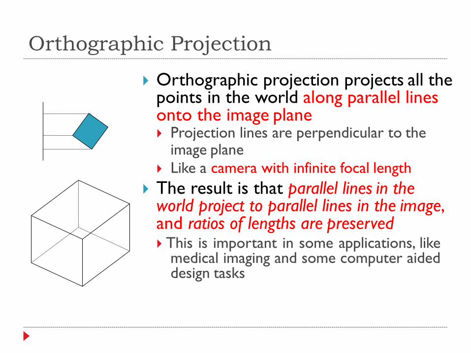
Orthographic Projection
} Orthographic projection projects all the points in the world along parallel lines onto the image plane} Projection lines are perpendicular to the
image plane} Like a camera with infinite focal length
} The result is that parallel lines in the world project to parallel lines in the image, and ratios of lengths are preserved} This is important in some applications, like
medical imaging and some computer aideddesign tasks

e
image plane
y
(0,0) x
g
Subtle point: it doesn’t precisely matter where we put the image plane
t,n
t,f
b,n
b,f
General Orthographic

xcanonical =Mview->canonicalxview
viewúú
úê
ûë ûêê
ê
ë
- (n + f ) (n - f )úê zview ú- (t+ b) (t-b) úê y- (r+ l) (r- l) ùéxview ù
= ê
viewúú
úê
ûë ûûë
êú ê
canonicalú = ê
û ëêêzcanonicalúêêy ú ê
ë
éxcanonicalù
úê 1 ú1
é2 (r - l)
úê 1 ú1- (n + f )2úê zview ú- (t+ b) 2 úê y
0 0 - (r+ l) 2 ùéxview ù1 00 10 01úê0
úê0úê00úê00ùé10 0
0 2 (t -b) 00 0 2 (n - f )0 0 0
0 00 2 (t -b) 00 0 2 (n - f )0 0 0
é2 (r - l)
1
Orthographic Projection Matrix(Orthographic View to Canonical Matrix)
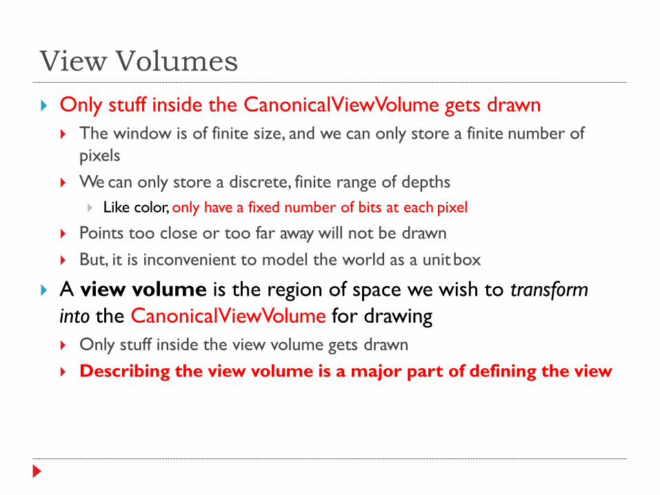
View Volumes} Only stuff inside the CanonicalViewVolume gets drawn
} The window is of finite size, and we can only store a finite number of pixels
} We can only store a discrete, finite range of depths} Like color, only have a fixed number of bits at each pixel
} Points too close or too far away will not be drawn} But, it is inconvenient to model the world as a unit box
} A view volume is the region of space we wish to transforminto the CanonicalViewVolume for drawing} Only stuff inside the view volume gets drawn} Describing the view volume is a major part of defining the view

} Pinhole cameras work in practice
Perspective Projection} Abstract camera model -
box with a small hole in it

Distant Objects Are Smaller

Basic Perspective Projection} We are going to temporarily ignore canonical view
space, and go straight from view towindow} Assume you have transformed to view space, withx
to the right,y up,and z back toward the viewer} Assume the origin of view space is at the center of
projection (the eye)} Define a focal distance,d,and put the image plane
there (note d is negative)} You can define d to control the size of the image

• If you know P(xv ,yv ,zv) and d, what is P(xs,ys)?– Where does a point in view space end up on the
screen?
xv
yv
-zvd
P(xv ,yv ,zv)P(xs,ys)
Basic Perspective Projection

} Similar triangles gives:
d zv d zv
xs = xv ys = yv
yv
-zv
P(xv,yv,zv)P(xs,ys)
View Planed
Basic Case

• Using homogeneous coordinates we canwrite:– Our next big advantage to homogeneous
coordinates
êë
ê
d úûêëd úû êz ú
v
ùê ú
êy ú º êy ú
ê zv úv
é xv
sú
éxs ù
vs
d
úP
úûêë
P = ê
10ú0ú
ê0ê0
é1 0 0 0ùê0 1 0 0ú
0 10
Simple Perspective Transformation

• The basic equations we have seen give a flavor of what happens, but they are insufficient for all applications
• They do not get us to a CanonicalViewVolume• They make assumptions about the viewing conditions• To get to a Canonical Volume, we need a Perspective
Volume …
General Perspective
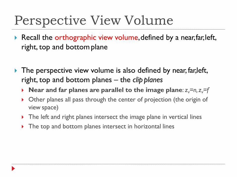
Perspective View Volume} Recall the orthographic view volume,defined by a near,far,left,
right, top and bottomplane
} The perspective view volume is also defined by near, far,left,right, top and bottom planes – the clip planes} Near and far planes are parallel to the image plane: zv=n, zv=f} Other planes all pass through the center of projection (the origin of
view space)} The left and right planes intersect the image plane in vertical lines} The top and bottom planes intersect in horizontal lines

Clipping Planes
xv
-zv
Near ClipPlane
Far ClipPlaneView
Volume
Left ClipPlane
Right ClipPlane
fn
l
r
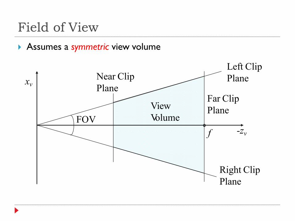
} Assumes a symmetric view volume
Field of View
xv
-zv
Near ClipPlane
Far ClipPlaneView
Volume
Left ClipPlane
Right ClipPlane
fFOV
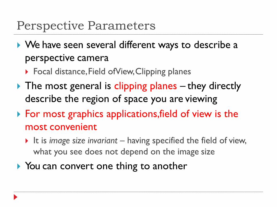
Perspective Parameters} We have seen several different ways to describe a
perspective camera} Focal distance,Field ofView,Clipping planes
} The most general is clipping planes – they directly describe the region of space you are viewing
} For most graphics applications,field of view is the most convenient} It is image size invariant – having specified the field of view,
what you see does not depend on the image size
} You can convert one thing to another

• You must have the image size to do this conversion– Why? Same d, different image size,different FOV
dd
FOV/2
height/2
÷øö
çèæ
÷ =è ø
heightæ FOV ö
2dFOV = 2 tan
2d height
2tanç
-1
Focal Distance to FOV
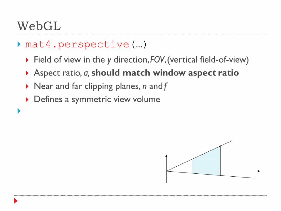
WebGL} mat4.perspective(…)
} Field of view in the y direction,FOV,(vertical field-of-view)} Aspect ratio, a, should match window aspect ratio} Near and far clipping planes, n and f} Defines a symmetric view volume
}
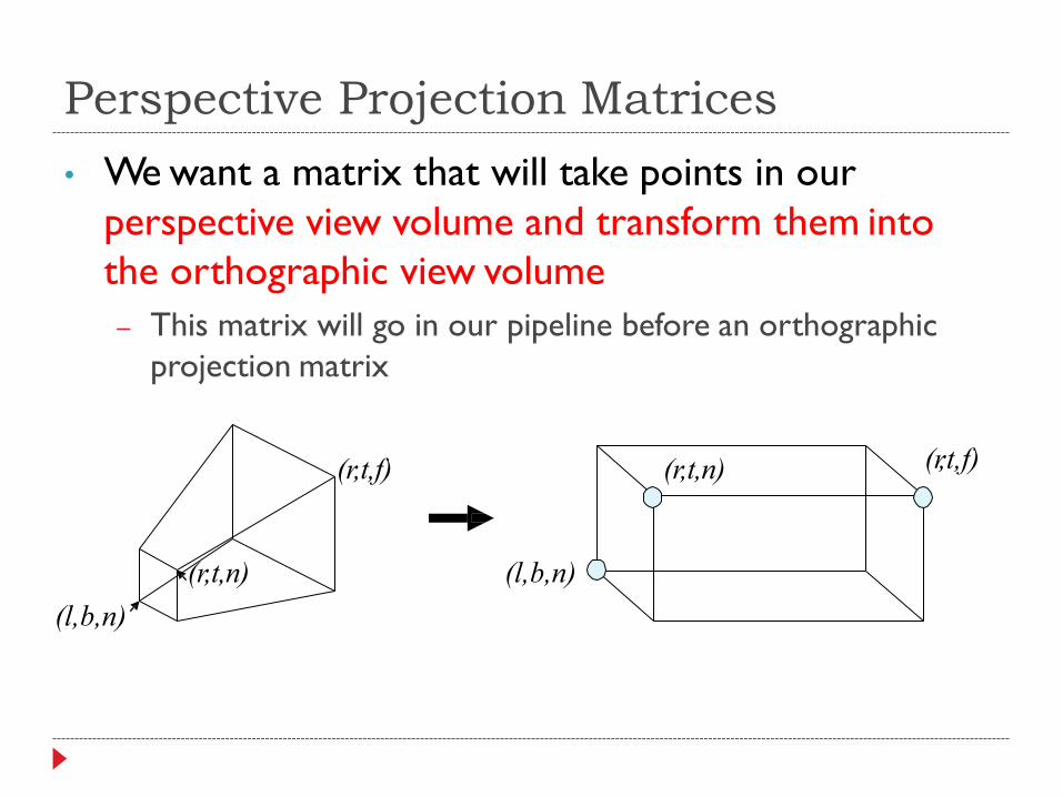
• We want a matrix that will take points in our perspective view volume and transform them into the orthographic view volume– This matrix will go in our pipeline before an orthographic
projection matrix
(l,b,n)(r,t,n) (l,b,n)
(r,t,n) (r,t,f)(r,t,f)
Perspective Projection Matrices

Mapping Lines} We want to map all the lines through
the center of projection to parallel lines} This converts the perspective case to the
orthographic case, we can use all our existing methods
} The relative intersection points of lines with the near clip plane should not change
} The matrix that does this looks like the matrix for our simple perspective case

• This matrix leaves points with z=n unchanged• It is just like the simple projection matrix, but it does
some extra things to z to map the depth properly• We can multiply a homogenous matrix by any number
without changing the final point, so the two matrices above have the same effect
û
ú º ê
ë û ë 0 úê0ê0
0 úê00 ù
ê0ê0
0 úú
- nf ú
0 ù én 0 0n 00 n + f0 1
é1 0 0ê0 1 0
0 (n + f ) n - f ú0 1 n 0 ú
MP = ê
General Perspective

• After applying the perspective matrix, we map the orthographic view volume to the canonical view volume:
úúû
ê
êêêêêë
0 ùú
1
0
0
0
0
0
0é 20 0n 0 0úê0 0 (n + f ) - nf
ú
ú0 1 0 ú
û(n - f ) úë0
0
2 - (n + f )úê(n - f )
0
(t - b)úê0
- (t+ b) úê0
2(t -b)
(r - l )úén- (r+ l)ù
ê(r - l)
O Pview->canonical
ê=M M =M
Mworld->canonical =Mview->canonicalMworld->view
xcanonical =Mworld->canonicalxworld
Complete Perspective Projection

END