images.pcmac.orgimages.pcmac.org/.../uploads/forms/rocket_assignment1.docx · web viewyou have the...
TRANSCRIPT

Rocket Project
With this project, you will learn about, research, and construct a model rocket that we will launch in class. You have the option of purchasing your own rocket kit from a hobby store and construct in class. If you do not have your own rocket, one will be provided for you.
In order to earn all of your points, you must do all of the following:
Read this packet
Answer the questions at the end of the packet and define the terms = 20 points
Research different types of Rockets and create a PowerPoint Presentation = 30 Points
Design a rocket using drafting tools = 20 Points
Build rocket = 30 Points
Launch!!!
PowerPoint Presentation must have the following:
Information on 2 different styles of Rockets = 10 Points Advantages of 3 different types of fins = 10 points Explanation of why you chose your design = 10 Points

LD01: Introduction to Model Rocketry
The Team America Rocketry Challenge The Team America Rocketry Challenge (TARC) was conceived originally as a way to promote interest in science and aerospace careers among high school students, and to celebrate the 100 th anniversary of the Wright brothers‟ 1903 flight. The response was so great that it became an annual event. Approximately 7,000 students from across the nation compete in TARC each year.
The Team America Rocketry Challenge is an aerospace design and engineering event for teams of US secondary school students (7th through 12th grades) run by the NAR and the Aerospace Industries Association (AIA). Teams can be sponsored by schools or by non-profit youth organizations such as Scouts, 4-H, or Civil Air Patrol (but not the NAR or other rocketry organizations). The goal of TARC is to motivate students to pursue aerospace as an exciting career field, and it is co-sponsored by the American Association of Physics Teachers, 4-H, the Department of Defense, and NASA. The event involves designing and building a model rocket (2.2 pounds or less, using NAR-certified model rocket motors totaling no more than 80.0 Newton-seconds of total impulse) that carries a payload of 1 Grade A Large egg for a flight duration of 40 - 45 seconds, and to an altitude of exactly 825 feet (measured by an onboard altimeter), and that then returns the egg to earth undamaged using only a streamer as a recovery device. Onboard timers are allowed; radio-control and pyrotechnic charges are not.
The first seven Team America Rocketry Challenges, held in 2003 through 2009, were the largest model rocket contests ever held. Co-sponsored by the NAR and the Aerospace Industries Association (AIA), the five events together attracted about 5,100 high-school teams made up of a total of over 50,000 students from all 50 states. These students had a serious interest in learning about aerospace design and engineering through model rocketry. The top 100 teams each year came to a final fly-off competition in late May near Washington, DC, to compete for $60,000 in prizes. These teams were selected based on the scores reported from qualification flights that they conducted locally throughout the US.
Team America Rocketry Challenge 2010's target flight duration of 40-45 seconds is measured from the moment of rocket liftoff until the egg payload lands. The target flight altitude of 825 feet is measured by an onboard altimeter. The top 100 teams from among all those who have entered will meet in a final fly-off competition on May 15, 2010 at Great Meadow, The Plains, VA. These top 100 teams will be selected based on the duration and altitude scores reported from local qualification flights that they conduct in front of an NAR Senior (adult) member observer at their choice of time, up until the flight deadline of April 5, 2010.
NAR
The National Association of Rocketry (NAR) is the organized body of rocket hobbyists. Chartered NAR sections conduct launches, connect modelers and support all forms of sport 33

rocketry. NAR was founded in 1957 to help young people learn about science and math through building and safely launching their own models.
4H 4-H has grown into a community of 6 million young people across America learning leadership, citizenship and life skills. 4-H can be found in every county in every state, as well as the District of Columbia, Puerto Rico and over 80 countries around the world. The 4-H community also includes 3,500 staff, 518,000 volunteers and 60 million alumni. 4-H'ers participate in fun, hands-on learning activities, supported by the latest research of land-grant universities, that are focused on three areas called Mission Mandates: Science, Engineering and Technology, Healthy Living and Citizenship.
The NAR 4H partnership In May 2007 the NAR and 4-H initiated a national partnership. The purpose of this alignment is to get more kids to fly rockets and form rocket clubs which will lead to more TARC teams, more people joining NAR and more kids becoming scientists and engineers Together 4H clubs and NAR sections can hold sport, contest or TARC launches. They can have training and building sessions, or work on science fair and engineering challenges using rocketry. 4H has many 'state fair' events that need innovative ideas for student projects. In serving young people 4H and NAR can both elevate the visibility of one another in their mutual community. The NAR has a wide range of online resources that are immediately useful to 4-H youth group leaders in organizing and running rocketry programs. NAR board members have had several planning meetings with the 4H National Council and Headquarters Directors. The first steps to implementing these plans are to establish connections between the organizations, such as this web link. Members from both groups need to get familiar with each other. As a few joint rocketry activities get started and promoted in some regions, other areas will get the idea and follow. 4H teams will eventually become big players in TARC. The goal is that in five years the partnership will have engaged over 100,000 students in a rocketry event.

LD02: The Model Rocket

THE BOOSTER SECTION
• Launch Lug – helps to guide the rocket upward until it reaches enough velocity for the fins to engage. • Parachute – assists in the safe recovery of the rocket. • Shock Cord – connects the parachute and nosecone to the booster. It absorbs the shock of ejection charge. • Shock Cord Attachment – attaches the shock cord to the booster section. • Centering Rings – attach the engine mount (and sometimes the fins) to the airframe. • Engine Mount – holds the rocket engine inside the rocket. • Engine Retainer – prevents the engine from being ejected by the ejection charge.
Fins – guides the rocket in a straight path.
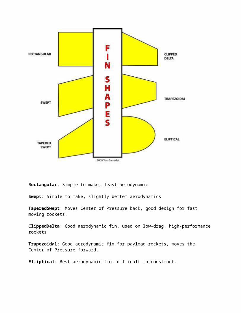
Fin Edges & Shapes

Rectangular: Simple to make, least aerodynamic
Swept: Simple to make, slightly better aerodynamics
TaperedSwept: Moves Center of Pressure back, good design for fast moving rockets.
ClippedDelta: Good aerodynamic fin, used on low-drag, high-performance rockets
Trapezoidal: Good aerodynamic fin for payload rockets, moves the Center of Pressure forward.
Elliptical: Best aerodynamic fin, difficult to construct.

Low Drag Clipped Delta Fin
To determine the dimensions of a low drag fin:
1. Determine the diameter of the airframe.
2. Multiply it by 2 to determine the root length and the span (C root and S)
3. The length of the tip (C tip) is equal to the airframe diameter.
4. The thickness of the fin at the root (T root) = 0.1 of the root length (C root).
5. The thickness of the fin at the tip (C tip) = 0.1 of the tip length (C tip)
6. To reduce the fin, reduce the C root and C tip only.
7. To increase the fin, increase the span (S) only.
Low Drag, High Performance Rocket The Paradigm–5 is an example of a low-drag, high performance model rocket design that uses a low-drag clipped delta fin.

Payload Section
• Nose – creates an aerodynamic shape. May also hold a payload.
• Airframe – holds the payloads in place.
• Bulkhead – separates the egg section from the electronics section, preventing vortex effect and causing a false altimeter reading.
• Altimeter – measures the changing air pressure to calculate apogee. Must have vent holes in airframe in order to operate properly.
• Tube Coupler – connects the payload section to the booster section by means of the shock cord. Also protects the payload from the ejection gases.
• Shock Cord Attachment – a metal eye for the secure attachment of the shock cord.
The Egg
• Eggs have an „arch structure‟ at each end that transfers pressure to the sides.
• About 35 Newtons of force is required to break an egg on its end and about 25N to break it on its side.

Nose Shape
Rocket noses are made of balsa, plastic, or fiberglass. For aircraft and rockets, below Mach .8, the nose pressure drag is essentially zero for all shapes and the major significant factor is friction drag. Having a smooth finish on the nose is more important than nose shape for rockets flying under the speed of sound.

Rocket Motor Sizes
• Motor diameter is measured in millimeters.
• Sizes for low to mid-power rockets are 13mm, 18mm, 24mm, and 29mm.
Engine or Motor?
• Something that imparts motion is called a motor.
• An engine is a machine that converts energy into mechanical motion.
• While referring to the propulsion system of a model rocket as a motor is more accurate, the use of the term engine is common.
Black Powder Motor B– The letter indicates the total impulse power produced by the motor. Each letter doubles the power. 6 – The first number gives the average thrust of the motor in Newtons. 4 – The last number indicates the delay seconds between the end of thrust and the ejection charge.

Black Powder Motor Burn
• Black powder motors burn from the rear forward.
• When the propellant is spent, it ignites the delay charge.
• The delay charge burns forward and ignites the ejection charge.
• The clay nozzle forces the pressure forward, expelling the nose cone and recovery system.

The parts of a Composite Reloadable Engine:
• The case is a reusable part that holds the propellant. Also reusable are the forward and aft closure.
• The nozzle is only used once and directs the thrust rearward.
• The composite propellant grain is a spongy material that does not break if dropped. It is the same type of propellant used in the NASA Space Shuttle boosters.
• The igniter is pushed all the way forward into the propellant grain.
• The delay element is installed inside the forward closure.
• The black powder ejection charge is held in place by a plastic cap.
Composite Motor Burn
• Composite motors burn from the inner core out.
• The delay element is ignited with the propellant and burns forward. Because of this, tracking smoke is produced immediately.
• The delay element ignites the ejection charge.
Parachute
Parachutes are made out of plastic, Mylar, or rip-stop nylon.
Shroud lines can be carpet thread or Kevlar chord.
The spill hole reduces oscillation and increased descent rate.
Oscillation is a swaying motion as the parachute spills air from its sides.
Adding a riser lifts the parachute out of the turbulence of the rocket, but increases the risk of parachute failure.

Streamers
Streamers are made out of crepe paper, Mylar, Dura-Lar, or rip-stop nylon.
The best length to width radio is 10:1 to create the most drag as the streamer flaps in the wind.
Streamer recovery is faster than parachute recovery and reduces the recovery area.


LD03: Newton’s Laws of Motion
Sir Isaac Newton was an English physicist, mathematician, astronomer, natural philosopher, and alchemist. In 1666, he witnessed an apple fall from its tree and he began to ponder why it fell down. This led to his Three Laws of Motion.
First Law of Motion: The Law of InertiaEvery body perseveres in its state of being at rest or of moving uniformly straight forward, except insofar as it is compelled to change its state by force impressed. Objects at rest will stay at rest (inertia) and objects in motion will stay in motion in a straight line unless acted upon be an unbalanced force. There is a natural tendency of objects to keep on doing what they're doing. All objects resist changes in their state of motion. In the absence of an unbalanced force, an object in motion will maintain this state of motion.
Second Law of Motion: The Law of Force The change of momentum of a body is proportional to the impulse impressed on the body, and happens along the straight line on which that impulse is impressed.
Acceleration is produced when a force acts on a mass. The greater the mass (of the object being accelerated) the greater the amount of force needed (to accelerate the object).
F = MA Force = Mass times Acceleration
A car that weighs 1,000 kg runs out of gas. The driver pushes the car to a gas station at a speed of 0.05 meters per second. How much force is the driver applying to the car to go that speed?
F = 1,000 kg x 0.05 m/s/s F = 50 Newtons of force
What the heck is a Newton?
The Newton is a unit of force.
It is equal to the amount of force required to accelerate a mass of one kilogram at a rate of one meter per second per second.
What the heck is a kilogram?
1 Kilo = 2.2 pounds
You Know The 2nd Law Already!
Everyone knows the Second Law: heavier objects require more force to move the same distance as lighter objects.

We know that we don‟t need the same amount of force to lift a feather that is needed to lift a bowling ball.
Third Law of Motion: The Law of Reciprocal Actions
For a force there is always an equal and opposite reaction: or the forces of two bodies on each other are always equal and are directed in opposite directions.
For every action, there is an equal and opposite reaction.
This means that for every force there is a reaction force that is equal in size, but opposite in direction. Whenever an object pushes another object it gets pushed back in the opposite direction with equal force.

LD04: Aerodynamics
Aerodynamics is the study of the motion of air, particularly when it interacts with a moving object. In physics the term dynamics customarily refers to the time evolution of physical processes.

Factors that Affect Aerodynamics
The Object: shape and size
The Motion: velocity and the inclination to flow
The Air: mass, viscosity, compressibility
Four Forces of Flight
Lift is a force used to stabilize and control the direction of flight.
Drag is the aerodynamic force parallel to the relative wind.
Weight is the force generated by gravity on the rocket.
Thrust is the force which moves the rocket forward.
Aerodynamic Forces
Aerodynamic forces are generated and act on a rocket as it flies through the air. The lift and drag act through the center of pressure which is the average location of the aerodynamic forces on an object.
Aerodynamic forces are mechanical forces. They are generated by the interaction and contact of the rocket with the air.
For lift and drag to be generated, the rocket must be moving through the air.
• Lift occurs when a flow of gas (the air) is turned by a solid object(the rocket).
• The flow is turned in one direction, and the lift is generated in the opposite direction.
For a model rocket, the nose, airframe, and fins can become a source of lift if the rocket‟s flight path is at an angle
When a solid body (the rocket) moves through a fluid (gas or liquid), the fluid resists the motion. The rocket is subjected to an aerodynamic force in a direction opposed to the motion which we call drag.

drag is aerodynamic friction, and one of the sources of drag is the skin friction between the molecules of the air and the solid surface of the moving rocket.
A boundary layer is the layer of air in the immediate vicinity of the rocket‟s surface. Boundary layers can be laminar (smooth flow) or turbulent (swirling).
The point in which a laminar boundary layer becomes turbulent is called the transition.
drag is also aerodynamic resistance to the motion of the object through the fluid. This source of drag depends on the shape of the rocket and is called pressure or form drag.
Interference drag occurs whenever two surfaces meet at sharp angles, such as at the fin roots. Interference drag creates a vortex which creates drag. Fin fillets reduce the effects of this drag.
Air passing by the tips of the fins form a fin tip vortex. Accelerating the air into this vortex causes drag on the fins, and a low pressure area behind them. Tapered fin tips reduce this drag.
Parasitic Drag is produced by objects like the launch lug. The launch lug can account for 30% of all drag. Cutting the lug‟s leading edge to 45 degrees reduces drag.

A model rocket‟s fin that is square on the edges creates a lot of drag and turbulence. If the fin‟s leading and trailing edges are sanded in a roundshape, called an airfoil, it reduces the drag.
Airfoil shape fins creates high pressure behind the fin and pushes it forward, cancelling out most of the pressure drag caused by the fins. This is called pressure recovery.
Weight is the force generated by the gravitational attraction on the rocket. The gravitational force is a field force; the source of the force does not have to be in physical contact with the object. Gravity affects the rocket whether it is stationary or moving (up or down).
Thrust is the force applied to the rocket to move it through the air, and through space. Thrust is generated by the propulsion system of the rocket through the application of Newton's Third Law of Motion. The direction of the thrust is normally along the longitudinal axis of the rocket through the rocket‟s center of gravity.

LD05: Rocket Stability
During the flight of a model rocket, gusts of wind or thrust instabilities, can cause the rocket to "wobble", or change its attitude in flight.
Poorly built or designed rockets can also become unstable in flight. This lesson is about what makes a rocket unstable in flight and what can be done to improve its stability.
Translation and Rotation A rocket in flight can move two ways; it can translate, or change its location from one point to another, and it can rotate, meaning that it can roll around on its axis.
Roll Most rockets are symmetric about a line from the tip of the nose to the center of the nozzle exit. We will call this line the roll axis and motion about this axis is called a rolling motion. The center of gravity lies along the roll axis.
Yaw and Pitch When a rocket wobbles from side to side, this movement is called a yaw motion. A pitch motion is an up or down movement of the nose of the rocket.
Center of Gravity – CG As a rocket flies through the air, it both translates and rotates. The rotation occurs about a point called the center of gravity, which is the average location of the weight of the rocket.

How to Determine the Center of Gravity
1. Load the motor, recovery system, and payload.
2. Tie a string around the airframe and adjust it until the rocket is horizontally balanced.
3. The location of the string is the center of gravity.
Center of Pressure – CP The average location of the pressure on the rocket is called the center of pressure. The parts of the rocket that influences the location of the center of pressure the most are the fins.
Building a Stable Rocket If the center of gravity is in front of the center of pressure, the rocket will return to its initial flight conditions if it is disturbed. This is called a restoring force because the forces "restore" the rocket to its initial condition and the rocket is said to be stable.

If the center of gravity and the center of pressure are in the same location, it is called neutral stability. A rocket with neutral stability may make a stable or unstable flight depending on the forces acting on it.
If the center of pressure is in front of the center of gravity, the lift and drag forces maintain their directions but the direction of the torque generated by the forces is reversed. This is called a de-stabilizing force. Any small displacement of the nose generates forces that cause the displacement to increase. Such a flight condition is unstable.
Correcting Unstable Flight To move the Center of Gravity:
• Add or remove weight in the nose cone.
• Redistribute the Payload
• Increase or decrease airframe length.
To move the Center of Pressure:
• Increase or reduce the fin size.
• Change the shape of the fins.
• Change the location of the fins.
• Increase or decrease airframe length/diameter

One Caliber Stability
The best separation between the center of gravity and the center of pressure is for the CP to be at least one body tube diameter in front of the CG. This is called one caliber stability.
Weather Cocking
• Following the liftoff of a model rocket, it often turns into the wind. This maneuver is called weather cocking and it is caused by forces, such as a strong wind, pushing on the side of the rocket‟s fins.
Causes of Weather Cocking
• Rockets with long airframes experience weather cocking, especially during the coast phase.
• Large fins present a larger surface area for the wind.
• Rockets with a center of gravity that is far in front of the center of pressure.
Tube Fins
• Using tube fins reduce weather cocking because of the aerodynamic side profile.
• Tube fins should be used carefully because these types of rockets tend to be unstable.
Design and Engineering
During the design and engineering phase, the students will learn how to design and run flight simulations on Rocksim, a model rocket computer program available from Apogee Components. The student will also receive a detailed hands-on presentation of the booster and payload section of the model rocket to include information on materials and construction, how to paint a rocket, rocket engines, the types of recovery systems used on model rockets, and how to safely launch rockets.

Construction
The construction of the students‟ model rockets may occur simultaneously with the design and engineering lessons. A good sequence is to give the design and engineering lesson specific to the part of construction that the students are about to begin. Because of the volume of rockets that the students will create, it is recommended that the educator devise some form of identification nomenclature for each rocket. The system that the researcher uses has worked well. The first digit is an S, for student or a T, for teacher. The next two digits are the last two numbers of the year. The last two to three digits represent the rocket number for the year. So the 51st rocket build by a student in 2009 would be S0951. The teacher‟s rocket may omit the year and start from the first rocket the teacher built and is written as T055 for the 55st rocket. The numbers are types on small adhesive mailing labels and affixed on the airframe. This is the number that the Chief Engineer will verify with Flight Control prior to launch.
ID03: Marker Streamer Construction and Use
Marker streamers are used as an inexpensive method of determining how high a model rocket flew by timing the streamer‟s return to Earth. These measuring devices are constructed by taping a 3 gram weight, such as a penny, on the end of a 1 inch wide by 12 inches long polyethylene tape that is .0001” of an inch thick. The purpose of the tape is not to produce drag, but to aid visibility of the streamer. High visibility colors such as florescent orange are a good choice. The streamer will fall at a constant rate of 18 feet per second. By timing the streamer’s drop from apogee to the ground, the rocket’s altitude can be determined by multiplying that number by 18.

Construction
1. Cut a 1 inch polyethylene tape to 12 inches
2. Place a penny (or other 3 gram flat object) on one end and fold the side of the tape around it to from a “V.”
3. Tape the penny in place.
4. Fold the marker streamer.
Use
1. Place the marker streamer into the body tube after the recovery system and shock cord has been packed.
2. Instruct the timer to begin timing when the streamer is ejects out of the body tube and to stop timing when the streamer lands.
3. To determine altitude, multiply the number of seconds from apogee to landing by 18. The result is the altitude in feet.

Questions
Answer the following questions by typing the answer into this document. You will save the entire document on your spot on the network and Mr. Baisden will come around and save onto a memory stick to grade. Make sure you save your file with your FULL NAME so that you will get full credit.
Define the following:
Launch Lug Parachute Shock Cord Shock Cord Attachment Centering Rings Engine Mount Engine Retainer
Fins
Nose
Airframe
Bulkhead
Altimeter
Tube Coupler
Shock Cord Attachment

1. List the steps to determine the dimensions of a low drag fin.
2. Name 3 nose cone shapes
3. Name and explain the four forces of flight.
4. How do you determine the center of gravity?
5. What is center of pressure?