vihiga county - samsamwater.com · intercalated interbedded - a lava flow may occur between layers...
TRANSCRIPT

HYDROGEOLOGICAL ASSESSMENT REPORT
Wambandu Primary School
L/R No. East Bunyore/Ebunangwe /912
Echichibulu Location, Emuhaya Division, Emuhaya District
VIHIGA COUNTY
***********
October, 2012
CONSULTANT:
Sebastian Namwamba
EARTHS SCOPE GEO- HYDRO SERVICES
Water, Sanitation and Environmental Engineering
P. O. Box 55127-00200
NAIROBI
Cell-phone: 0720-438377
Signed:
Date

HHyyddrrooggeeoollooggiiccaall && GGeeoopphhyyssiiccaall IInnvveessttiiggaattiioonnss WWaammbbaanndduu PPrriimmaarryy SScchhooooll,, EEmmuuhhaayyaa DDiissttrriicctt,, VViihhiiggaa CCoouunnttyy,, KKeennyyaa..
EEaarrtthhss SSccooppee GGeeoo -- HHyyddrroo SSeerrvviicceess OOccttoobbeerr 22001122,, PPaaggee ii
SUMMARY
Introduction
This report presents the results of hydrogeological and geophysical investigations to
evaluate groundwater resources for Wambandu Primary School - Wambandu in Emuhaya
district, Vihiga County, Kenya. The borehole will be used to supply water to the School
and surrounding community, thus supplementing water from springs and roof catchment
in the area.
Climate
The climate in the area is mainly humid type, with a bi-modal rainfall pattern. Long rains
are experienced in March to July while short rains occur in August to October. The main
source of rainfall over Wambandu region is the Lake Victoria. It occurs in form of either
convectional or frontal rainfall. The mean annual rainfall ranges between 1100 and 2700
mm. The mean maximum and minimum temperatures in the area are given as 27oC and
15oC respectively. Evaporation is relatively low and increases from less than 1400 mm to
1800 mm per year.
Geology
The regional geology of the investigated area is dominated by the Basement System
Complex which can be divided into two groups: - (a) The Basement Complex rocks,
(sedimentary in origin) and the (b) The undeformed post- Basement formations. The
geology of the investigated site include, the recent deposits which include lateric iron
stone resulting to production of thick red soils. These are underlain by the Kavirondian
series rocks consisting of feldspathic grits, conglomerates, shale and siltstones. Granites
are the major intrusives in the area.
Geophysical Fieldwork
Geophysical fieldwork was executed on 27th
September 2012. The resistivity method was
used for the present investigations. Geophysical measurements were used to determine the
thickness of the underlying layers, their potential as aquifers, and the expected quality of
groundwater in these formations .One vertical electrical soundings were executed on
selected points.
Conclusions
From the present study it is concluded that the prospects for sufficient groundwater for use
in the station are good, based on the geological and hydrogeological evidence gathered.
Recommendations for Drilling
Drilling of a Borehole to a minimum of 130 m bgl and a maximum of 150m bgl is
recommended at the location of the VES. The recommended drilling site is known to Mr.
Isaac Kisambo (Head teacher) – 0720984101. The borehole should be drilled at 8‟‟
diameter and installed with 6" diameter uPVC casings and screens with high % open
surface area. Recommendations are given for borehole construction and completion
methods.The importance of correct and comprehensive techniques in this particular
aspect cannot be over-emphasized.
Generally, the water quality is expected to be good.

HHyyddrrooggeeoollooggiiccaall && GGeeoopphhyyssiiccaall IInnvveessttiiggaattiioonnss WWaammbbaanndduu PPrriimmaarryy SScchhooooll,, EEmmuuhhaayyaa DDiissttrriicctt,, VViihhiiggaa CCoouunnttyy,, KKeennyyaa..
EEaarrtthhss SSccooppee GGeeoo -- HHyyddrroo SSeerrvviicceess OOccttoobbeerr 22001122,, PPaaggee iiii
Monitoring
Regular monitoring should be instituted and maintained in the borehole in order to keep
track of groundwater levels. A piezometer should be installed in the borehole to be able to
monitor the water level in the well.
Drilling
Before drilling starts, a groundwater permit should be applied for from the Water Resources
Management Authority (WRMA), Lake Victoria North Drainage Basin –Regional Office in
Kakamega.
Additional recommendations for borehole drilling, installation, development and are given
in Appendix 1

HHyyddrrooggeeoollooggiiccaall && GGeeoopphhyyssiiccaall IInnvveessttiiggaattiioonnss WWaammbbaanndduu PPrriimmaarryy SScchhooooll,, EEmmuuhhaayyaa DDiissttrriicctt,, VViihhiiggaa CCoouunnttyy,, KKeennyyaa..
EEaarrtthhss SSccooppee GGeeoo -- HHyyddrroo SSeerrvviicceess OOccttoobbeerr 22001122,, PPaaggee iiiiii
TABLE OF CONTENTS
1. INTRODUCTION ............................................................................................................................................... 1
2. BACKGROUND INFORMATION ................................................................................................................... 2
2.1. LOCATION ................................................................................................................................................... 2 2.2. VEGETATION AND CLIMATE ........................................................................................................................ 2 2.3. TOPOGRAPHY AND DRAINAGE .................................................................................................................... 2 2.4. EXISTING WATER SUPPLY AND DEMAND .................................................................................................... 2
3. GEOLOGY .......................................................................................................................................................... 4
3.1. REGIONAL GEOLOGY .................................................................................................................................. 4 3.1.1. Precambrian .......................................................................................................................................... 4 3.1.2. Cretaceous ............................................................................................................................................. 4 3.1.3. Tertiary .................................................................................................................................................. 4 3.1.4. Pleistocene to Recent............................................................................................................................. 5
3.2. GEOLOGICAL ROCK FORMATIONS ............................................................................................................... 5 3.2.1. Pleistocene and Recent Deposits ........................................................................................................... 5 3.2.2. Older Rocks ........................................................................................................................................... 5 3.2.3. Kavirondian System ............................................................................................................................... 5 3.2.4. Nyanzian System .................................................................................................................................... 6 3.2.5. Basement System ................................................................................................................................... 6
3.3. GEOLOGY OF THE INVESTIGATED SITE ........................................................................................................ 6
4. HYDROGEOLOGY ........................................................................................................................................... 8
4.1. GROUNDWATER OCCURRENCE ................................................................................................................... 8 4.2. BASEMENT AQUIFER OCCURRENCE ............................................................................................................ 8 4.3. WEATHERING AND ITS SIGNIFICANCE IN AQUIFER OCCURRENCE ................................................................ 9
4.3.1. The Collapsed Zone ............................................................................................................................... 9 4.3.2. Saprolite ................................................................................................................................................ 9 4.3.3. Saprock .................................................................................................................................................. 9 4.3.4. Bedrock ................................................................................................................................................. 9 4.3.5. Regolith ............................................................................................................................................... 10
4.4. HYDROGEOLOGY OF THE WAMBANDU AREA ............................................................................................ 10 4.5. HYDRAULIC CHARACTERISTICS OF THE AQUIFER ...................................................................................... 11
4.5.1. Specific Capacity ................................................................................................................................. 11 4.5.2. Transmissivities ................................................................................................................................... 11 4.5.3. The Storage Coefficient ....................................................................................................................... 11 4.5.4. Recharge Mechanisim ......................................................................................................................... 11 4.5.5. Groundwater Movement ...................................................................................................................... 12
4.6. GROUNDWATER QUALITY ......................................................................................................................... 12
5. GEOPHYSICAL INVESTIGATION METHODS ......................................................................................... 13
5.1. RESISTIVITY METHOD ............................................................................................................................... 13 5.2. BASIC PRINCIPLES ..................................................................................................................................... 13 5.3. VERTICAL ELECTRICAL SOUNDINGS (VES). .............................................................................................. 14
6. FIELDWORK AND RESULTS ....................................................................................................................... 15
6.1. FIELDWORK ............................................................................................................................................... 15 6.2. INTERPRETATION RESULTS ....................................................................................................................... 15
7. CONCLUSIONS AND RECOMMENDATIONS .......................................................................................... 16
RECOMMENDATIONS ................................................................................................................................................ 16
8. REFERENCES .................................................................................................................................................. 17

HHyyddrrooggeeoollooggiiccaall && GGeeoopphhyyssiiccaall IInnvveessttiiggaattiioonnss WWaammbbaanndduu PPrriimmaarryy SScchhooooll,, EEmmuuhhaayyaa DDiissttrriicctt,, VViihhiiggaa CCoouunnttyy,, KKeennyyaa..
EEaarrtthhss SSccooppee GGeeoo -- HHyyddrroo SSeerrvviicceess OOccttoobbeerr 22001122,, PPaaggee iivv
FIGURES
Figure 1: Site location map of the Investigated Area ............................................................................................... 3 Figure 2: Geological Map of the Study Area ............................................................................................................ 7 Figure 3: Interpretation Graph for VES1 ............................................................................................................... 15
TABLES
Table 1: VES Interpretation Results for the Investigated Site .............................................................................. 15
AAPPPPEENNDDIICCEESS
Appendix 1: Drilling and Construction of A Borehole ............................................................................................ 19 Appendix 2: Acceptable Ionic Concentration - Various authorities ....................................................................... 22

HHyyddrrooggeeoollooggiiccaall && GGeeoopphhyyssiiccaall IInnvveessttiiggaattiioonnss WWaammbbaanndduu PPrriimmaarryy SScchhooooll,, EEmmuuhhaayyaa DDiissttrriicctt,, VViihhiiggaa CCoouunnttyy,, KKeennyyaa..
EEaarrtthhss SSccooppee GGeeoo -- HHyyddrroo SSeerrvviicceess OOccttoobbeerr 22001122,, PPaaggee vv
LIST OF ABBREVIATIONS AND GLOSSARY OF TERMS
ABBREVIATIONS: (NOTE: SI spellings used throughout).
EC Electrical Conductivity (in micro Seimens/centimetre)
km kilometres
m metres
m amsl metres above mean sea level
m bgl metres below ground level
ppm parts per million, equivalent to mg/l
swl static water level (in m bgl) (the piezometric level or water table, see
below)
TDS Total Dissolved Solids (ppm)
wsl water struck level (in m bgl)
GLOSSARY OF TERMS:
Aquifer A geological formation or structure which transmits water and which
may supply water to wells, boreholes or springs.
Confined Confined aquifers are those in which the piezometric level is higher
(i.e., at a greater elevation relative to sea level) than the elevation at
which the aquifer was encountered.
Intercalated Interbedded - a lava flow may occur between layers of sediment, or
vice-versa.
Recharge The general term indicating the process of transport of water from
surface sources (i.e., from rivers or rainfall) to groundwater storage.
Volcanics Here used as a general term describing geological material of
volcanic origin.

HHyyddrrooggeeoollooggiiccaall && GGeeoopphhyyssiiccaall IInnvveessttiiggaattiioonnss WWaammbbaanndduu PPrriimmaarryy SScchhooooll,, EEmmuuhhaayyaa DDiissttrriicctt,, VViihhiiggaa CCoouunnttyy,, KKeennyyaa..
EEaarrtthhss SSccooppee GGeeoo--HHyyddrroo SSeerrvviicceess OOccttoobbeerr 22001122,, PPaaggee 11
11.. IINNTTRROODDUUCCTTIIOONN
Earths Scope Geo-Hydro Services was commissioned by Wambandu Primary School to
undertake groundwater resources investigations on their 0.7 Acres piece of land in Emuhaya
Division , Emuhaya District, Vihiga County , Kenya. Fieldwork was carried out on 27th
September 2012.
The objective of the investigations was to assess the availability of groundwater and to
advise on the viability of drilling a productive borehole. The investigation comprised a
detailed desk study in which the available relevant geological and hydrogeological data
were collected, analyzed, collated and evaluated within the context of the Client's
requirements. This was followed by hydrogeological and geophysical field investigations,
data acquisition, analysis and reporting. The data sources included information gathered
from reports of previous hydrogeological investigations in the area.

HHyyddrrooggeeoollooggiiccaall && GGeeoopphhyyssiiccaall IInnvveessttiiggaattiioonnss WWaammbbaanndduu PPrriimmaarryy SScchhooooll,, EEmmuuhhaayyaa DDiissttrriicctt,, VViihhiiggaa CCoouunnttyy,, KKeennyyaa..
EEaarrtthhss SSccooppee GGeeoo--HHyyddrroo SSeerrvviicceess OOccttoobbeerr 22001122,, PPaaggee 22
22.. BBAACCKKGGRROOUUNNDD IINNFFOORRMMAATTIIOONN
22..11.. LLooccaattiioonn
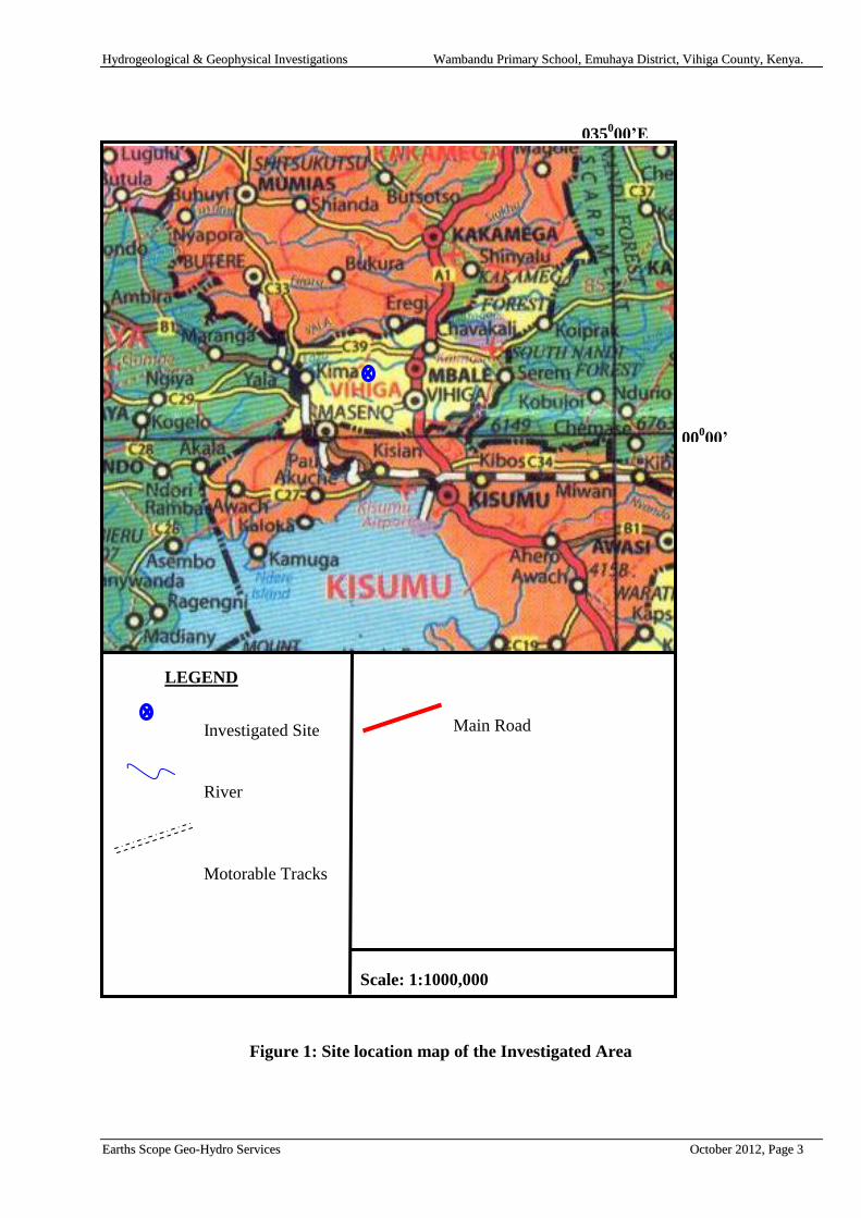
The site is located in Wambandu Village, Echichibulu Location, Emuhaya Division,
Emuhaya District of Vihiga County. The approximate location of the site is defined by
co-ordinates 36 N 0685117, UTM 0010825. The location of the site is shown on Figure 1.
22..22.. VVeeggeettaattiioonn aanndd CClliimmaattee
The vegetation in the area is natural moist forest vegetation, comprising riverine
vegetation along rivers and thick bushes and woodland with dense under growth in the
undulating plains. Agriculture is practiced in small scale due to the nature of sub-division
of the land in the area and has led to depletion of natural vegetation. The crops grown
include maize, bean, sorghum and cassava. The area is generally humid, with average
annual rainfall in the range 1100-2700 mm. The mean maximum and minimum
temperature are in the range of 26-28 o
C and 14-16 oC respectively. The area is classified
as warm.
22..33.. TTooppooggrraapphhyy aanndd DDrraaiinnaaggee
The area is generally rocky and characterized by undulating broad flat topped divides and
long gentle valley slopes. The altitude over the investigated area is about 1515 m amsl.
The drainage in the area is largely controlled by Lake Victoria, with River Yala draining
the upper lands and flowing into the Lake. River Tsava , a tributary of River Yala drains
the immediate area.The River Yala is confined to the out crop of the Granite rocks. While
its valley forms the lowest part of the area, the river flows over a rocky bed which is
undergoing excavation at the present day flowing southwards into the Lake.
22..44.. EExxiissttiinngg WWaatteerr SSuuppppllyy aanndd DDeemmaanndd
The current water supplies consist of roof catchment and two springs located about 500m
away.
The current water demand factors a school population of 470 and about 250 Households
within the area. The water demand in the area is about 20m3 per day.
HHyyddrrooggeeoollooggiiccaall && GGeeoopphhyyssiiccaall IInnvveessttiiggaattiioonnss WWaammbbaanndduu PPrriimmaarryy SScchhooooll,, EEmmuuhhaayyaa DDiissttrriicctt,, VViihhiiggaa CCoouunnttyy,, KKeennyyaa..
EEaarrtthhss SSccooppee GGeeoo--HHyyddrroo SSeerrvviicceess OOccttoobbeerr 22001122,, PPaaggee 33
Figure 1: Site location map of the Investigated Area
00000’
LEGEND
Main Road
Scale: 1:1000,000
035000’E
Investigated Site
River
Motorable Tracks
HHyyddrrooggeeoollooggiiccaall && GGeeoopphhyyssiiccaall IInnvveessttiiggaattiioonnss WWaammbbaanndduu PPrriimmaarryy SScchhooooll,, EEmmuuhhaayyaa DDiissttrriicctt,, VViihhiiggaa CCoouunnttyy,, KKeennyyaa..
EEaarrtthhss SSccooppee GGeeoo--HHyyddrroo SSeerrvviicceess OOccttoobbeerr 22001122,, PPaaggee 44
33.. GGEEOOLLOOGGYY
33..11.. RReeggiioonnaall GGeeoollooggyy
The geological history of the area can be followed from the Precambrian era, which is
represented by the metamorphic rocks of the „Basement System. The regional
metamorphism was followed by various cycles of erosion, faulting and graben formation,
deposition of continental sediments and volcanic activity.
33..11..11.. PPrreeccaammbbrriiaann
During this period, vast successions of sediments accumulated in a geosynclinal structure
that covered most of the present Central and Eastern Africa. Towards the end of the era, a
period of regional folding and metamorphism occurred. This large-scale tectonic activity
subjected the original rocks to high temperatures and pressures, which caused partial
melting. This was followed by re-crystallization and growth of new minerals. Depending
on the parent material and the prevailing pressures and temperatures, various types of
granites, gneisses and schists were formed.
Due to the tectonic events that followed their creation, the metamorphosed rocks were
intensely folded, tilted, and dissected by intrusive granitic dykes and domes. In addition,
granitization processes resulted in the formation of granulites and migmatites.
33..11..22.. CCrreettaacceeoouuss
During the Cretaceous, there existed a peneplain which is represented by a chain of high
points of uniform elevation in the Nandi highlands (Osorongai T.S., 7,006 ft.; Sumayat,
7,005 ft.), and continues south of the present area at similar level .The age of this
peneplain is thought to be Cretaceous and it has been correlated with the Kisii Highlands
peneplain some 160 km further south. This was followed by along period of erosion and
emplacement of minor intrusion
33..11..33.. TTeerrttiiaarryy
This is the period of Mt Elgon volcanic eruption, at the time of commencement of activity
the Basement surface possessed more or less the present characters. The volcanics of
mount Elgon never spread very far south or east beyond its present position. Below the
volcanic lavas were the sediments named the Bugishu series believed to be of Middle
Tertiary.

HHyyddrrooggeeoollooggiiccaall && GGeeoopphhyyssiiccaall IInnvveessttiiggaattiioonnss WWaammbbaanndduu PPrriimmaarryy SScchhooooll,, EEmmuuhhaayyaa DDiissttrriicctt,, VViihhiiggaa CCoouunnttyy,, KKeennyyaa..
EEaarrtthhss SSccooppee GGeeoo--HHyyddrroo SSeerrvviicceess OOccttoobbeerr 22001122,, PPaaggee 55
33..11..44.. PPlleeiissttoocceennee ttoo RReecceenntt
This period was dominated by further evolution of the majority of the rivers. These areas
are now on or below the level of the End-Tertiary Peneplain which lies some 100 to 190
m below the sub Miocene surface. Its presence is suggested by the plateau gravels,
consisting of well rounded quartz pebbles further away from the river, prominent
superficial deposits from weathered and eroded rock surfaces. Black valley soils and
lateritic soils are good example of the recent formations.
33..22.. GGeeoollooggiiccaall RRoocckk ffoorrmmaattiioonnss
There are three main rock formations that have been identified in the study area. These
are described in chronological order here below.
33..22..11.. PPlleeiissttoocceennee aanndd RReecceenntt DDeeppoossiittss
These are presented by river terraces and plateau gravels, black valley soils, laterite and
an often deep soil cover. River deposits consist of broad belts of marshy black, valley
soils and occur in the valleys of many rivers. This type of river deposits is especially the
characteristic of the Kavirondian terrain. In Basement area small alluvial sand and gravel
deposits are more common. More so the terrace gravel consisting of ungraded, rounded,
water-worn pebbles up to 6 inch diameter, mostly of agglomeratic type but with some
derived from granitic and the Basement gneiss might be found along some rivers e.g.
river Malakisi. The laterites is widespread and occur on all the rock type examined. The
quartz gravel of 1 foot thick band floats occurs at varying depth mostly over the north –
east of the area below the brown and red sandy soils. A deep soil cover has formed over
much of the area. The decomposition of Tertiary volcanics produces a rich dark red-
brown soils regarded best for agricultural purposes. The remainder of the area is covered
by somewhat lighter coloured sandy soils on the peneplain, with exception of the area of
gneissose leuco-granite which has a cover of highly quartzose acid soil but little removed
from freshly disintegrated rock and of little agricultural value.
33..22..22.. OOllddeerr RRoocckkss
Underlying the Pleistocene and Recent deposits, are the older rocks divided into two:- (a)
the Kavirondian System and (b) Nyanzian System.
33..22..33.. KKaavviirroonnddiiaann SSyysstteemm
The Kavirondian rocks are poorly exposed except in the valley of river Nzoia. In both the
arenaceous and the argillaceous members faint banding is recognizable at times, graded
bedding is sometime apparent and on occasion current –bedding also. Owing to the
proximity of granitic contacts to the sediments of the Nzoia valley, they have seldom
escaped contact metamorphic effects, and the development of the flakes of red brown
biotite is common. The so called “talcy” clays of the Bungoma area are derived by the
break down of Kavirondian rocks.

HHyyddrrooggeeoollooggiiccaall && GGeeoopphhyyssiiccaall IInnvveessttiiggaattiioonnss WWaammbbaanndduu PPrriimmaarryy SScchhooooll,, EEmmuuhhaayyaa DDiissttrriicctt,, VViihhiiggaa CCoouunnttyy,, KKeennyyaa..
EEaarrtthhss SSccooppee GGeeoo--HHyyddrroo SSeerrvviicceess OOccttoobbeerr 22001122,, PPaaggee 66
33..22..44.. NNyyaannzziiaann SSyysstteemm
Rocks of the Nyanzian System are exposed over a relatively small area and consist of
sheared, but otherwise unaltered, rhyollite with some small tuff. The main outcrop occurs
as a narrow band bounded by faults, on or near the crest of the Nandi escarpment and
continues into the area to the south. This band continues as numerous lenticular
discontinuous thrust sheets in the area of the Broderick Falls area. Nyanzian rocks or their
equivalents have not previously been found in contact with rocks of the Basement System
in Kenya or Tanzania.
33..22..55.. BBaasseemmeenntt SSyysstteemm
The Basement System rocks of the area do not show the diversity of high grade
metamorphic type which characterizes other areas of Basement System rocks surveyed in
Kenya. They consist of schist gneiss and migmatites derived from an original sedimentary
succession, which has been transformed by regional metamorphism and recrystallisation
during orogenic earth movements into foliated quartz and feldspar rich rocks with
variable amount of biotite and/or hornblende, locally abundant epidote and more rarely
garnet. Originally pure qurtzose sand stone now occur as granular quartzites, with small
amounts of muscovites, and originally less pure sandstone are now presented by quartz-
mica schists. Hornblende schists and garnetiferous hornblende schist are believed to
represent original basic intrusives. Granitic sheet and vein intrusions and pegmatite vein
are common, especially in the south of the area. Some degree of granitisation has affected
all the basement system rocks of the area, with the exception of the quartzite and related
rocks.
33..33.. GGeeoollooggyy ooff tthhee IInnvveessttiiggaatteedd SSiittee
The area is overlain by recent deposits of eroded and decayed hard capping of lateritic
iron stone resulting to production of a thick mantle of heavy red soil. Beneath this is high-
level gravel deposits. This is underlain by the Kavirondian Series which consist of the
sediments of felspathic grits, conglomerates, shale and siltstone. The Kavirondian series
has been heavily intruded by a complex of intrusions. These intrusion are granites of
several distinct types. The granites are part of Kitosh Batholith, whose outcrop covers
very considerable tracts of the country north of the River Yala. These rocks are usually
porphyritic, coarse-grained, hornblende-biotite granite .

HHyyddrrooggeeoollooggiiccaall && GGeeoopphhyyssiiccaall IInnvveessttiiggaattiioonnss WWaammbbaanndduu PPrriimmaarryy SScchhooooll,, EEmmuuhhaayyaa DDiissttrriicctt,, VViihhiiggaa CCoouunnttyy,, KKeennyyaa..
EEaarrtthhss SSccooppee GGeeoo--HHyyddrroo SSeerrvviicceess OOccttoobbeerr 22001122,, PPaaggee 77
Figure 2: Geological Map of the Study Area
LEGEND
γPC
Scale: 1:1000,000
035030’E
00000’E
Investigated Site
Olivine Basalts
Rhyolites, Andesites,
Basalts and
Greywackes
PreCambrian
Intrusives
Mv2
PD2
+ + +
+ + +
PreCambrian Intrusive
Geological Boundary
Observed
Motorable Tracks
Main Road

HHyyddrrooggeeoollooggiiccaall && GGeeoopphhyyssiiccaall IInnvveessttiiggaattiioonnss WWaammbbaanndduu PPrriimmaarryy SScchhooooll,, EEmmuuhhaayyaa DDiissttrriicctt,, VViihhiiggaa CCoouunnttyy,, KKeennyyaa..
EEaarrtthhss SSccooppee GGeeoo--HHyyddrroo SSeerrvviicceess OOccttoobbeerr 22001122,, PPaaggee 88
44.. HHYYDDRROOGGEEOOLLOOGGYY
The hydrogeology of an area is normally intimately dependent upon the nature of the parent
rock, structural features, weathering processes, recharge mechanism and the form and
frequency of precipitation. The midland environment of Western Kenya area offers a
reasonable groundwater potential. The relatively high rainfall, and the gently peneplain
surface south of Elgon and west of the Nandi escarpment are all favorable characteristics to
ground water occurrence.
44..11.. GGrroouunnddwwaatteerr OOccccuurrrreennccee
Given that suitable storage media exist below ground, the mechanisms by which water
must reach it also affect aquifer potential. Obviously, if no rainfall or riverflow is able to
percolate to a sandy weathered Basement aquifer due to the presence of an aquitard
(impermeable layer) probably clay, the actual potential is very low. If rainfall is low, the
volume of water, which may eventually percolate to a suitable aquifer, is likely to be
relatively small, and possibly mineralized due to high evaporation.
Percolation is dependent on soil structure, vegetation coverage and the erosion state of the
parent rock. Rocks which weather to clayey soils will naturally inhibit percolation (such
as „black cotton‟ soils); conversely, the sandy soils resulting from the erosion of some
Basement System rocks are eminently suited to deep swift percolation.
Recharge is the term applied to the whole mechanism, and includes all the aspects of
parent geology, effective rainfall and percolation. Some aquifer systems are recharged by
water falling a substantial distance away.
Generally there are two types of aquifers that exist within the Basement System rock.
These include those associated with fault and fracture feature and weathered rocks
overlying compact or fresh rock.
44..22.. BBaasseemmeenntt AAqquuiiffeerr OOccccuurrrreennccee
Aquifers associated with fault and fracture features are better than the weathered rock
aquifers overlying compact or fresh rock. These latter aquifers, located in the regolith, are
highly variable in terms of potential yields. This is because the physical transmission of
water within the aquifer body itself is dependent upon the total clay fraction present after
weathering of the parent rock which itself depends on the chemical constitutes of the
parent rock and the mechanism of weathering.
Faults and fractures associated with major movements of the earth‟s crust and often
accompanied by tectonic activity, lead to the formation of coarser material. This, together
with the larger volume of potential storage brought about by the fault, leads to rather
better potential yields, especially where a borehole is sited so as to intersect fault features
at depth.

HHyyddrrooggeeoollooggiiccaall && GGeeoopphhyyssiiccaall IInnvveessttiiggaattiioonnss WWaammbbaanndduu PPrriimmaarryy SScchhooooll,, EEmmuuhhaayyaa DDiissttrriicctt,, VViihhiiggaa CCoouunnttyy,, KKeennyyaa..
EEaarrtthhss SSccooppee GGeeoo--HHyyddrroo SSeerrvviicceess OOccttoobbeerr 22001122,, PPaaggee 99
44..33.. WWeeaatthheerriinngg aanndd iittss SSiiggnniiffiiccaannccee iinn AAqquuiiffeerr OOccccuurrrreennccee
Different zones may be identified in the weathering profile of an area. These are detailed
below.
44..33..11.. TThhee CCoollllaappsseedd ZZoonnee
This may show marked lateral variation but is general sandy on watershed areas with
illuviated clay near the base and sometimes a „stone line‟; on valley slopes, colluvial
material accumulates and in valley bottoms, secondary clay minerals predominate. Slope
bottom laterites may also occur which can result in perched water tables. Permeabilities
vary in accordance with lithology on watersheds. The collapsed zone normally occurs
above the water table.
44..33..22.. SSaapprroolliittee
This is covered by the collapsed zone and is mainly composed of more coarsely
disintegrated and less altered rock material. It is derived by situ weathering from the
bedrock but is disaggregated. Permeability commonly increases at lower levels due to a
lesser development of secondary clay minerals.
44..33..33.. SSaapprroocckk
This is weathered bedrock. It resembles the bedrock zone and is the most important local
aquifer type. Fracture permeability generally increased as a result of weathering (as
compared with fresh bedrock) unless in filled by illuviated clay minerals.
44..33..44.. BBeeddrroocckk
This includes the variably fractured fresh bedrock and the saprock or weathered bedrock.
The saprock-fresh bedrock junction is generally transitional or even fluctuating in banded
sequences. Fracture systems are related either to decompression or to tectonic forces. The
former tend to be sub-horizontal with a decreasing frequency with depth. The latter tend
to be sub-vertical and are often in zonal concentrations. Since tectonic fracturing in
Basement rocks has occurred on several occasions over a long time span and often with
reactivation of old fractures, clear recognition of age or differentiation of shear and tensile
conditions is not to be expected.
Fissure permeability is assumed to correlate to some degree with frequency of fracture
occurrence, with a further assumption that both parameters will decrease with depth.
However, the few detailed studies do not always present comparable features, variations
being probably due to limitations of the database. Fracture distribution probably reflects
fracture systems mainly of decompression type. Fracture sealing in the weathered bedrock

HHyyddrrooggeeoollooggiiccaall && GGeeoopphhyyssiiccaall IInnvveessttiiggaattiioonnss WWaammbbaanndduu PPrriimmaarryy SScchhooooll,, EEmmuuhhaayyaa DDiissttrriicctt,, VViihhiiggaa CCoouunnttyy,, KKeennyyaa..
EEaarrtthhss SSccooppee GGeeoo--HHyyddrroo SSeerrvviicceess OOccttoobbeerr 22001122,, PPaaggee 1100
profile is known to occur, probably by clay illuviation, and may result in an increasing
permeability with depth. Fracture occurrence and permeability in the main bedrock may
show an inverse relationship of depth to permeability with large data set. The depth-
permeability relationships at individual borehole sites are obviously affected by the dip of
tectonic fracture zones.
44..33..55.. RReeggoolliitthh
The regolith consists of the collapsed zone and the saprolite. Since weathering is most
effective in the vadose zone and the zone of water table fluctuations, there is a tendency
to develop subdivisions into an upper and lower saprolite relative to current (or previous)
water levels. This is in addition sometimes to a basal brecciated zone where rock
fragmentation is largely unaccompanied by mineralogical changes.
In regions of moderate to high annual rainfall (>600 mm/year), the water table is typically
at shallow levels (<10-15 m) and the regolith aquifer provides the main storage for deep
boreholes as well as both storage and transmissivity for wells and shallow boreholes.
The collapsed zone has developed from the underlying saprolite by further dissolution
and leaching, combined with other formative processes: chemical, physical and
biological. The surface material is typically sandy on watershed areas where these overlie
quartz- rich rocks but changes to sandy clays and clay (montmorrillonite) in valley bottom
lands. The surface sands have high infiltration capacities, which decrease markedly in any
underlying illuviated clay horizons.
Saprolite is derived from in situ weathering and is disaggregated. An upper saprolite may
be distinguished by higher proportions of the more advanced minerals combined with the
earlier forms of secondary clay minerals (smectites). The boundary with the underlying
saprock may be sharp (against coarser-grained, massive rock) or transitional (against
banded or finer-grained rocks)
.
44..44.. HHyyddrrooggeeoollooggyy ooff tthhee WWaammbbaanndduu AArreeaa
The regional catchment for this area extends further southwest towards the lake Victoria.
The effective catchment is limited by the Nandi Escarpments, which has done much to
maintain a copious rainfall over the higher part of the area. The type of rainfall is
convenctional, which is the major characteristic of Lake Victoria Basin. The major river
is river Yala and is very largely drained by its tributaries and sub tributaries. Groundwater
recharge is mainly by direct percolation and precipitation. Groundwater in this area
occurs within the perched water table resting on resistant bands of pegmatitic granite in
pervious weathered biotite granite, weathered and fractured Basement System rocks
overlying the fresh Basement system rock of granitic origin. In places where Basement
rocks are banded, groundwater is expected to be found within weathered or fractured
bands. Recharge is also expected to be via lateral flow over a long distance in well
developed joint system which may offer free passage to water. The weathered zone
immediately below the overburden is saturated and may contain promising amounts of
ground water as a result of damming by other minor intrusives.

HHyyddrrooggeeoollooggiiccaall && GGeeoopphhyyssiiccaall IInnvveessttiiggaattiioonnss WWaammbbaanndduu PPrriimmaarryy SScchhooooll,, EEmmuuhhaayyaa DDiissttrriicctt,, VViihhiiggaa CCoouunnttyy,, KKeennyyaa..
EEaarrtthhss SSccooppee GGeeoo--HHyyddrroo SSeerrvviicceess OOccttoobbeerr 22001122,, PPaaggee 1111
It is thus expected that the groundwater potential in the area is medium with the
promising aquifer occurring within the weathered and fractured Basement system.
44..55.. HHyyddrraauulliicc CChhaarraacctteerriissttiiccss ooff tthhee AAqquuiiffeerr
44..55..11.. SSppeecciiffiicc CCaappaacciittyy
This is a crude indication of the efficiency of the borehole as an engineered structure, and is
calculated by dividing the discharge rate (as m3/day) by the total drawdown. High specific
capacities generally indicate high transmissivities, low specific capacities the opposite
44..55..22.. TTrraannssmmiissssiivviittiieess
This is the rate of flow of water under a unit hydraulic gradient through a cross section of
unit width across the entire saturated section of the aquifer. Strictly speaking, transmissivity
should be determined from the analysis of a well test, but here we use the Logan method to
estimate it; Logan developed a relationship between specific capacity and transmissivity
based on a reworking of Thiem‟s seminal steady-state groundwater flow equation.
The product of (K) and thickness (D) is defined as the transmissivity (T) of an aquifer system (KD=T). This property can be derived from the commonly applied Jacobs formula (Driscoll 1986):
T=1.22Q/Δs
Where: Δs = increase in drawdown over 1 log cycle of time.
44..55..33.. TThhee SSttoorraaggee CCooeeffffiicciieenntt
The storage coefficient of an aquifer is the volume of water released from or taken up per unit surface
area per unit change in head. It is dimensionless. Empirical values of the storage coefficient cannot be
determined from test data collected from pervious drilling programmes in the Eskot area, as aquifer
test data is not available. In an aquifer test, a borehole is pumped at a known discharge rate and water
levels in one or more neighbouring observation boreholes, and the shape and type of drawdown curve
in the observation borehole(s) is used to calculate the storage coefficient.
44..55..44.. RReecchhaarrggee MMeecchhaanniissiimm
The mechanism of recharge (and the rate of replenishment) of the sediment aquifers in the investigated
area has not been fully established. However a broad pattern of recharge can be described. The two
possible recharge mechanisms are direct recharge at the surface through infiltration and percolation and
indirect recharge via faults.
If the infiltration rate is low due to the presence of an aquiclude like clays, the recharge to the aquifer is
low. Percolation will depend on the soil structure, vegetation cover and the state of erosion of the
parent rock. A regolith aquifer may contain sufficient transmissivity and storage to provide sustained
groundwater yields from either hand dug wells or boreholes. However, the main transmissivity is
usually found in basal regolith, which is mechanically disaggregated, but with few or no secondary
clay minerals.

HHyyddrrooggeeoollooggiiccaall && GGeeoopphhyyssiiccaall IInnvveessttiiggaattiioonnss WWaammbbaanndduu PPrriimmaarryy SScchhooooll,, EEmmuuhhaayyaa DDiissttrriicctt,, VViihhiiggaa CCoouunnttyy,, KKeennyyaa..
EEaarrtthhss SSccooppee GGeeoo--HHyyddrroo SSeerrvviicceess OOccttoobbeerr 22001122,, PPaaggee 1122
In the Basement System aquifers, recharge occurs mainly during the rainy seasons either as direct
precipitation or via fault lines that intercept the various rivers in the area.. Although groundwater in the
Basement and alluvial aquifers occur in localised aquifer system, there is likelihood that regionally an
interconnection with the sedimentary aquifers through faults/fractures, and probably moves south-
eastwards from the recharge areas to ultimately discharge into the Indian Ocean. However there is no
evidence to support this view in view of the very limited information.
Available recharge is in fact the determining factor for the amount of abstractable ground water. In the
study area, the recharge probably does not exceed 1% of the total precipitation as is common in arid
and semi arid areas. The Basement aquifers are recharged mainly through outcrops with open fractures
or partly weathered rock surfaces, because the clay layer, which developed on top of the weathered
zone prevents the infiltration of rainwater. Infiltration of seasonal waters from will considerably
increase the amount of recharge but requires a hydraulic connection between the river and the aquifer.
44..55..55.. GGrroouunnddwwaatteerr MMoovveemmeenntt
Groundwater movement from recharge area to discharge area depends on the available
recharge, the aquifer characteristics and the mode of discharge. In the area under
consideration, these conditions are not uniform, mainly due to variations in precipitation
in different recharge areas of the same system and geological conditions of the
underground. The ground water is believed to be moving in the north south direction
towards the Tana River.
44..66.. GGrroouunnddwwaatteerr QQuuaalliittyy
From observation of water from the three shallow wells in the Wambandu area,
groundwater quality is generally good in colour, turbidity, odour and taste.
This therefore qualifies the intended uses area. However, the client is cautioned not to use
the water for drinking purposes before the water undergoes bacteriological tests.

HHyyddrrooggeeoollooggiiccaall && GGeeoopphhyyssiiccaall IInnvveessttiiggaattiioonnss WWaammbbaanndduu PPrriimmaarryy SScchhooooll,, EEmmuuhhaayyaa DDiissttrriicctt,, VViihhiiggaa CCoouunnttyy,, KKeennyyaa..
EEaarrtthhss SSccooppee GGeeoo--HHyyddrroo SSeerrvviicceess OOccttoobbeerr 22001122,, PPaaggee 1133
55.. GGEEOOPPHHYYSSIICCAALL IINNVVEESSTTIIGGAATTIIOONN MMEETTHHOODDSS
A great variety of geophysical methods are available to assist in the assessment of
geological subsurface conditions. In the present survey resistivity (also known as the
geoelectrical method) has been used.
55..11.. RReessiissttiivviittyy MMeetthhoodd
Vertical electrical soundings (VES) were carried out to probe the condition of the sub-
surface and to confirm the existence of deep groundwater. The VES investigates the
resistivity layering below the site of measurement. This technique is described below.
55..22.. BBaassiicc PPrriinncciipplleess
The electrical properties of rocks in the upper part of the earth's crust are dependent upon
the lithology, porosity, the degree of pore space saturation and the salinity of the pore
water. Saturated rocks have lower resistivities than unsaturated and dry rocks. The higher
the porosity of the saturated rock, the lower its resistivity, and the higher the salinity of the
saturating fluids, the lower the resistivity. The presence of clays and conductive minerals
also reduces the resistivity of the rock.
The resistivity of earth materials can be studied by measuring the electrical potential
distribution produced at the earth's surface by an electric current that is passed through the
earth.
The resistance R of a certain material is directly proportional to its length L and
cross-sectional area A, expressed as:
R = Rs * L/A (Ohm) (1)
where Rs is known as the specific resistivity, characteristic of the material and independent
of its shape or size. With Ohm's Law,
R = dV/I (Ohm) (2)
where dV is the potential difference across the resistor and I is the electric current through
the resistor, the specific resistivity may be determined by:
Rs = (A/L) * (dV/I) (Ohm.m) (3)

HHyyddrrooggeeoollooggiiccaall && GGeeoopphhyyssiiccaall IInnvveessttiiggaattiioonnss WWaammbbaanndduu PPrriimmaarryy SScchhooooll,, EEmmuuhhaayyaa DDiissttrriicctt,, VViihhiiggaa CCoouunnttyy,, KKeennyyaa..
EEaarrtthhss SSccooppee GGeeoo--HHyyddrroo SSeerrvviicceess OOccttoobbeerr 22001122,, PPaaggee 1144
55..33.. VVeerrttiiccaall EElleeccttrriiccaall SSoouunnddiinnggss ((VVEESS))..
When carrying out a resistivity sounding, current is led into the ground by means of two
electrodes. With two other electrodes, situated near the centre of the array, the potential
field generated by the current is measured. From the observations of the current strength
and the potential difference, and taking into account the electrode separations, the ground
resistivity can be determined.
While carrying out the resistivity sounding the separation between the electrodes is step-
wise increased (in what is known as a Schlumberger Array), thus causing the flow of
current to penetrate greater depths. When plotting the observed resistivity values against
depth on double logarithmic paper, a resistivity graph is formed, which depicts the variation
of resistivity with depth.
This graph can be interpreted with the aid of a computer program and the actual resistivity
layering of the subsoil is obtained. The depths and resistivity values provide the
hydrogeologist with information on the geological layering and thus the occurrence of
groundwater.

HHyyddrrooggeeoollooggiiccaall && GGeeoopphhyyssiiccaall IInnvveessttiiggaattiioonnss WWaammbbaanndduu PPrriimmaarryy SScchhooooll,, EEmmuuhhaayyaa DDiissttrriicctt,, VViihhiiggaa CCoouunnttyy,, KKeennyyaa..
EEaarrtthhss SSccooppee GGeeoo--HHyyddrroo SSeerrvviicceess OOccttoobbeerr 22001122,, PPaaggee 1155
66.. FFIIEELLDDWWOORRKK AANNDD RREESSUULLTTSS
66..11.. FFiieellddwwoorrkk
Field work was carried out on 27th
September 2012. One Vertical Electrical Sounding was
executed in order to unveil the hydrostratigraphy of the area. The hydrogeological
conditions of the investigated site in general are considered to be fairly uniform and the
results of the VES are representative of the prevailing stratigraphy of the investigated site.
66..22.. IInntteerrpprreettaattiioonn RReessuullttss
The interpretation results of the VES are tabulated in the Table below.
Table 1: VES Interpretation Results for the Investigated Site
VES LAYER 1
RE DE
LAYER 2
RE DE
LAYER 3
RE DE
LAYER 4
RE DE
1 107 0.6 441 5 165 100 1500 > 100
RE: Resistivity, DE: Depth
The interpretation results show a top superficial layer of resistivity of 107 Ohm-m to a
depth 0.6 m bgl interpreted to be dry sandy clay soils. This is underlain by a 441 Ohm-m
resistivity layer to a depth of 5.0 m bgl interpreted to be slightly weathered granodiorites.
Underlying this is a high resistivity layer of 165 Ohm-m to a depth of about 100 m bgl
interpreted to be weathered granodiorite. Below this and to greater depths occurs a high
resistivity layer of 1500 Ohm-m interpreted to be fresh Basement rocks
The resistivity layer of 165 Ohm-m at 100 m bgl is interpreted as the aquiferous layer and
water strike are expected in this layer. Water strikes are also expected at shallower depths
but this is considered insignificant and unsustainable .No water strikes are expected in the
fresh Basement rocks.
The interpreted VES graph is presented below.
Figure 3: Interpretation Graph for VES1

HHyyddrrooggeeoollooggiiccaall && GGeeoopphhyyssiiccaall IInnvveessttiiggaattiioonnss WWaammbbaanndduu PPrriimmaarryy SScchhooooll,, EEmmuuhhaayyaa DDiissttrriicctt,, VViihhiiggaa CCoouunnttyy,, KKeennyyaa..
EEaarrtthhss SSccooppee GGeeoo--HHyyddrroo SSeerrvviicceess OOccttoobbeerr 22001122,, PPaaggee 1166
77.. CCOONNCCLLUUSSIIOONNSS AANNDD RREECCOOMMMMEENNDDAATTIIOONNSS
From the geological, hydrogeological and geophysical evidence gathered, it is concluded
that the investigated area is located in a hydrogeological zone characterized by a medium
groundwater potential.
Medium and deep aquifers are expected in this area depending on the depths of faults,
fractured and weathered zones. A borehole drilled in this area with an adequate
sustainable water supply for the client should target water bearing units within the
weathered, faulted and fractured zones as aquifers are expected within these zones.
Shallow aquifers have however proved unfeasible and unsustainable.
RReeccoommmmeennddaattiioonnss
In view of the above it is recommended that:
An 8" borehole is drilled to a minimum depth of 130 m and a maximum depth
of 150 m at the location of the VES. Drilling should penetrate the deep aquifer for
maximum and sustainable yield.
The borehole should be installed with a Water Meter and an airline/piezometer to
monitor groundwater abstraction and to facilitate regular measurements of the static
water level in the borehole.
Upon drilling completion, a 2-litre water sample from the borehole should be
collected for reference to the WRMA Testing Laboratory, or any other competent
Water Testing Authority for a full physical, chemical and bacteriological analysis
before the water is put to any use.
A copy of the analysis report must be sent to the WRMA – Regional Office for
record.
The recommended drilling site is known to Mr. Isaac Kisambo (Head teacher) –
0720984101.
In Appendix 1, additional recommendations on the construction and completion of a
borehole are given.

HHyyddrrooggeeoollooggiiccaall && GGeeoopphhyyssiiccaall IInnvveessttiiggaattiioonnss WWaammbbaanndduu PPrriimmaarryy SScchhooooll,, EEmmuuhhaayyaa DDiissttrriicctt,, VViihhiiggaa CCoouunnttyy,, KKeennyyaa..
EEaarrtthhss SSccooppee GGeeoo--HHyyddrroo SSeerrvviicceess OOccttoobbeerr 22001122,, PPaaggee 1177
88.. RREEFFEERREENNCCEESS
C STANSFIELD HITCHEN, 1937,Geological Survey Of Kenya of No.2 Mining
Area, - KAVIRONDO
JONES M J., 1985, The Weathered Zone Aquifers of the Basement Complex
areas of Africa. Q.J eng. Geol. London. Vol. 18 pp 35-46.
BRAUN et al (1982): "Agro-climatic zone map of Kenya", Kenya Soil Survey
DRISCOLL F.G., 1986. Groundwater and Wells, 2nd
Ed. Johnson Division.
E. P SAGGERSON, 1952. Geology of the Kisumu District, Ministry of Natural
Resources, Geological Survey of Kenya, Report no. 21.
LAKE BASIN DEVELOPMENT AUTHORITY, 1988. Rural Domestic Water
Resources Assessment-Kisumu District.
JAPAN INTERNATIONAL COOPERATION AGENCY (JICA)., 1992. The Study on
the National Water Master Plan, Sectoral Report (B) Hydrology.
SOMBROEK, W G; BRAUN, H M H; AND VAN DER POUW, B J A; (1982) –
Explaratory Soil Map and Agro-climatic Zone Map of Kenya, 1980, Kenya Soil Survey.

HHyyddrrooggeeoollooggiiccaall && GGeeoopphhyyssiiccaall IInnvveessttiiggaattiioonnss WWaammbbaanndduu PPrriimmaarryy SScchhooooll,, EEmmuuhhaayyaa DDiissttrriicctt,, VViihhiiggaa CCoouunnttyy,, KKeennyyaa..
EEaarrtthhss SSccooppee GGeeoo--HHyyddrroo SSeerrvviicceess OOccttoobbeerr 22001122,, PPaaggee 1188
APPENDICES

HHyyddrrooggeeoollooggiiccaall && GGeeoopphhyyssiiccaall IInnvveessttiiggaattiioonnss WWaammbbaanndduu PPrriimmaarryy SScchhooooll,, EEmmuuhhaayyaa DDiissttrriicctt,, VViihhiiggaa CCoouunnttyy,, KKeennyyaa..
EEaarrtthhss SSccooppee GGeeoo--HHyyddrroo SSeerrvviicceess OOccttoobbeerr 22001122,, PPaaggee 1199
Appendix 1: Drilling and Construction of A Borehole
Drilling Technique
Drilling should be carried out with an appropriate tool - either percussion or rotary
machines will be suitable, though the latter are considerably faster. Geological rock samples
should be collected at 2 metre intervals. Struck and rest water levels and if possible,
estimates of the yield of individual aquifers encountered, should also be noted.
Well Design
The design of the well should ensure that screens are placed against the optimum aquifer
zones. An experienced hydrogeologist should make the final design.
Casing and Screens
The well should be cased and screened with good quality material. Owing to the depth of
the borehole, it is recommended to use steel casings and screens of high open surface area.
We strongly advise against the use of torch-cut steel well casing as screen. In general, its use
will reduce well efficiency (which leads to lower yield), increase pumping costs through
greater drawdown, increase maintenance costs, and eventually reduction of the potential
effective life of the well.
Gravel Pack
The use of a gravel pack is recommended within the aquifer zone, because the aquifer could
contain sands or silts which are finer than the screen slot size. An 8" diameter borehole
screened at 6" will leave an annular space of approximately 1", which should be sufficient.
Should the slot size chosen be too large, the well will pump sand, thus damaging the
pumping plant, and leading to gradual `siltation' of the well. The slot size should be in the
order of 1.5 mm. The grain size of the gravel pack should be an average 2 - 4 mm.
Well Construction
Once the design has been agreed, construction can proceed. In installing screen and
casing, centralizers at 6 metre intervals should be used to ensure centrality within the
borehole. This is particularly important to insert the artificial gravel pack all around the
screen. If installed, gravel packed sections should be sealed off top and bottom with clay
(2 m).
The remaining annular space should be backfilled with an inert material, and the top five
metres grouted with cement to ensure that no surface water at the well head can enter the
well bore and thus prevent contamination
Well Development
Once screen, pack, seals and backfill have been installed, the well should be developed.
Development aims at repairing the damage done to the aquifer during the course of drilling
by removing clays and other additives from the borehole walls. Secondly, it alters the

HHyyddrrooggeeoollooggiiccaall && GGeeoopphhyyssiiccaall IInnvveessttiiggaattiioonnss WWaammbbaanndduu PPrriimmaarryy SScchhooooll,, EEmmuuhhaayyaa DDiissttrriicctt,, VViihhiiggaa CCoouunnttyy,, KKeennyyaa..
EEaarrtthhss SSccooppee GGeeoo--HHyyddrroo SSeerrvviicceess OOccttoobbeerr 22001122,, PPaaggee 2200
physical characteristics of the aquifer around the screen and removes fine particles.
We do not advocate the use of over pumping as a means of development since it only
increases permeability in zones, which are already permeable. Instead, we would
recommend the use of air or water jetting, or the use of the mechanical plunger, which
physically agitates the gravel pack and adjacent aquifer material. This is an extremely
efficient method of developing and cleaning wells.
Well development is an expensive element in the completion of a well, but is usually
justified in longer well-life, greater efficiencies, lower operational and maintenance costs
and a more constant yield. Within this frame the pump should be installed at least 2 m
above the screen, certainly not at the same depth as the screen.
Well Testing
After development and preliminary tests, a long-duration well test should be carried
out. Well tests have to be carried out on all newly completed wells, because apart from
giving an indication of the quality of drilling, design and development, it also yields
information on aquifer parameters, which are vital to the hydrogeologist.
A well test consists of pumping a well from a measured start level (Water Rest Level -
(WRL) at a known or measured yield, and simultaneously recording the discharge rate and
the resulting drawdown as a function of time. Once a dynamic water level (DWL) is
reached, the rate of inflow to the well equals the rate of pumping. Usually the rate of
pumping is increased stepwise during the test each time equilibrium has been reached (Step
Drawdown Test). Towards the end of the test a water sample of 2 liters should be collected
for chemical analysis.
The duration of the test should be 24 hours, followed by a recovery test for a further 24
hours, or alternatively until the initial WRL has been reached (during which the rate of
recovery to WRL is recorded). The results of the test will enable a hydrogeologist to
calculate the optimum pumping rate, the pump installation depth, and the drawdown for a
given discharge rate.

HHyyddrrooggeeoollooggiiccaall && GGeeoopphhyyssiiccaall IInnvveessttiiggaattiioonnss WWaammbbaanndduu PPrriimmaarryy SScchhooooll,, EEmmuuhhaayyaa DDiissttrriicctt,, VViihhiiggaa CCoouunnttyy,, KKeennyyaa..
EEaarrtthhss SSccooppee GGeeoo--HHyyddrroo SSeerrvviicceess OOccttoobbeerr 22001122,, PPaaggee 2211
Schematic design for borehole completion
NB: Not to scale
Groundlevel
Cement grout
Inert backfill
Bentonite seal
2-4 mm Gravel pack
Bottom cap
Groundlevel
Concrete slab Well cover
Plain casing
Sanitary casing
Screens
Schematic Design for Borehole completion

HHyyddrrooggeeoollooggiiccaall && GGeeoopphhyyssiiccaall IInnvveessttiiggaattiioonnss WWaammbbaanndduu PPrriimmaarryy SScchhooooll,, EEmmuuhhaayyaa DDiissttrriicctt,, VViihhiiggaa CCoouunnttyy,, KKeennyyaa..
EEaarrtthhss SSccooppee GGeeoo--HHyyddrroo SSeerrvviicceess OOccttoobbeerr 22001122,, PPaaggee 2222
Appendix 2: Acceptable Ionic Concentration - Various authorities
World Health Organization: European Community:
1983 1971 Int. EC Directive 1980 relating to the quality
Guidelines; Standards; of water intended for human consumption:
Substance or Guideline Upper limit Guide Level Max. Admissible
Characteristic Value
Inorganic Constituents of health significance;
Antimony Sb 0.01
Arsenic As 0.05 0.05 0.05
Cadmium Cd 0.005 0.01 0.005
Chromium Cr 0.05 0.05
Cyanide CN 0.10 0.05 0.05
Fluoride F 1.5 1.7 1.5
Lead Pb 0.05 0.10 0.05
Mercury Hg 0.001 0.001 0.001
Nickel Ni 0.05
Nitrates 10 (as N) 45 (as N03) 25 (as NO3) 50 (as NO3)
Selenium Se 0.01 0.01
Other Substances GV: Highest Maximum GV: MAC:
Desirable Permissible
Level: Level:
Aluminum, Al 0.20 0.05 0.20
AmmoniumNH4 0.05 0.50
Barium , Ba 0.10
Boron B 1.0
Calcium, Ca 75 50 100
Chloride, Cl 250 200 600 25
Copper , Cu 0.05 0.10
Hydrogen
Sulphide, H2S ND ND
Iron Fe 0.30 0.10 1.0 0.05 0.20
Magnesium Mg 0.10 30 150 30 50
Manganese, Mn 0.10 0.05 0.50 0.02 0.05
Nitrite, NO2 0.10
Potassium, K 10 12
Silver, Ag 0.01
Sodium, Na 200 20 175
Sulphate, SO4 400 200 400 25 250
Zinc, Zn 5.0 15 0.10
T D S 1000 500 1500 1500
Total Hardness as CaCO3 500 100 500
Colour oHazen 15 5 50 1 20
Odour Inoffensive Unobjectionable 2 or 3 TON
Taste Inoffensive Unobjectionable 2 or 3 TON
Turbidity (JTU) 5 5 25 0.4 4
pH 6.5 - 8.5 7.0 - 8.5 6.5 - 9.2 6.5 - 8.5 9.5 (max.)
TemperatureoC 12 25
EC uS/cm 400
Notes ND - Not Detectable IO - Inoffensive
GL - Guide Level UO - Unobjectionable
(Based on Table 6.1, in Twort, Law & Crowley, 1985).