virginia transportation research council research report · final report survey of cathodic...
TRANSCRIPT

Virginia Transportation Research Council, 530 Edgemont Road,Charlottesville, VA 22903-2454, www.vtrc.net, (434) 293 -1900
http://www.virginiadot.org/vtrc/main/online_reports/pdf/07-r35.pdf
Final Report VTRC 07-R35
research reportSurvey
of Cathodic Protection Systemson Virginia Bridges
Virginia Transportation Research Council
STEPHEN R. SHARP, Ph.D.Research Scientist
MICHAEL C. BROWN, Ph.D., P.E.Research Scientist

Standard Title Page - Report on Federally Funded Project 1. Report No.: 2. Government Accession No. 3. Recipient’s Catalog No. FHWA/VTRC 07-R35
4. Title and Subtitle: 5. Report Date: Survey of Cathodic Protection Systems on Virginia Bridges June 2007 6. Performing Organization Code 7. Author(s): Stephen R. Sharp, Ph.D., and Michael C. Brown, Ph.D., P.E.
8. Performing Organization Report No.: VTRC 07-R35
9. Performing Organization and Address: 10. Work Unit No. (TRAIS) Virginia Transportation Research Council
530 Edgemont Road 11. Contract or Grant No.: Charlottesville, VA 22903 78005 12. Sponsoring Agencies' Name and Address:
13. Type of Report and Period Covered: Final
Virginia Department of Transportation Federal Highway Administration 1401 E. Broad Street 400 North 8th Street, Room 750 14. Sponsoring Agency Code Richmond, VA 23219 Richmond, VA 23219-4825 15. Supplementary Notes 16. Abstract
The Virginia Department of Transportation uses cathodic protection (CP) systems on steel-reinforced concrete structures to
extend the life of these structures. The purpose of this study was to identify, categorize, and evaluate the performance of the CP systems that have been used on these structures. These systems included galvanic anode CP (GACP) systems and impressed current CP (ICCP) systems. Some of these systems are exposed to chloride ions because of their location in a marine environment; others are on structures located inland that are exposed to chloride ions through the use of deicing salts.
The study showed that greater care needs to be taken to transfer the maintenance and monitoring responsibilities of CP
systems that are installed as part of a research study once the study is concluded. Further, some of these CP systems have not been associated with favorable research findings. Moreover, evaluation of inspection reports indicates that procedures are not in place to qualify VDOT bridge inspectors to monitor or evaluate CP systems and to record important data to ensure sufficient CP protection is being achieved with each CP system. Finally, the CP system cannot be treated as a stand-alone appendage during the design and construction of a structure; it must be considered in conjunction with the other electrical systems on a structure.
The initial cost of an ICCP system is not substantially different from the direct cost of a rehabilitative overlay that would be
required should such a system not be installed. If properly maintained, a retrofitted ICCP system would be expected to extend the life of a rehabilitated deck an additional 35 years. However, even with the cost of routine monitoring, an ICCP system can provide substantial savings in maintenance and user costs. Similarly, if a GACP system can prevent the need for repairs on approximately 16% of a substructure surface over the life of the structure, the costs of the GACP system would be approximately equal to that of a single rehabilitative intervention.
Based on the results of this study, by preserving the structure and extending the life of the initial structure with a CP system, a future rehabilitation can be deferred or prevented and fewer intermediate repairs will be necessary. This can have significant implications for users of a structure, particularly on congested urban or arterial routes. Further, some CP systems do not require a significant investment in monitoring or maintenance, thereby reducing long-term costs that have sometimes been associated with CP. 17 Key Words 18. Distribution Statement Bridge, cathodic protection, chloride, concrete, corrosion, galvanic, rebar, reinforcing steel, sacrificial, transportation, Virginia
No restrictions. This document is available to the public through NTIS, Springfield, VA 22161.
19. Security Classif. (of this report) 20. Security Classif. (of this page) 21. No. of Pages 22. Price Unclassified Unclassified 40
Form DOT F 1700.7 (8-72) Reproduction of completed page authorized

FINAL REPORT
SURVEY OF CATHODIC PROTECTION SYSTEMS ON VIRGINIA BRIDGES
Stephen R. Sharp, Ph.D. Research Scientist
Michael C. Brown, Ph.D., P.E.
Research Scientist
Virginia Transportation Research Council (A partnership of the Virginia Department of Transportation
and the University of Virginia since 1948)
In Cooperation with the U.S. Department of Transportation Federal Highway Administration
Charlottesville, Virginia
June 2007
VTRC 07-R35

ii
DISCLAIMER
The contents of this report reflect the views of the authors, who are responsible for the facts and the accuracy of the data presented herein. The contents do not necessarily reflect the official views or policies of the Virginia Department of Transportation, the Commonwealth Transportation Board, or the Federal Highway Administration. This report does not constitute a standard, specification, or regulation.
Copyright 2007 by the Commonwealth of Virginia. All rights reserved.

iii
ABSTRACT
The Virginia Department of Transportation uses cathodic protection (CP) systems on steel-reinforced concrete structures to extend the life of these structures. The purpose of this study was to identify, categorize, and evaluate the performance of the CP systems that have been used on these structures. These systems included galvanic anode CP (GACP) systems and impressed current CP (ICCP) systems. Some of these systems are exposed to chloride ions because of their location in a marine environment; others are on structures located inland that are exposed to chloride ions through the use of deicing salts.
The study showed that greater care needs to be taken to transfer the maintenance and
monitoring responsibilities of CP systems that are installed as part of a research study once the study is concluded. Further, some of these CP systems have not been associated with favorable research findings. Moreover, evaluation of inspection reports indicates that procedures are not in place to qualify VDOT bridge inspectors to monitor or evaluate CP systems and to record important data to ensure sufficient CP protection is being achieved with each CP system. Finally, the CP system cannot be treated as a stand-alone appendage during the design and construction of a structure; it must be considered in conjunction with the other electrical systems on a structure.
The initial cost of an ICCP system is not substantially different from the direct cost of a
rehabilitative overlay that would be required should such a system not be installed. If properly maintained, a retrofitted ICCP system would be expected to extend the life of a rehabilitated deck an additional 35 years. However, even with the cost of routine monitoring, an ICCP system can provide substantial savings in maintenance and user costs. Similarly, if a GACP system can prevent the need for repairs on approximately 16% of a substructure surface over the life of the structure, the costs of the GACP system would be approximately equal to that of a single rehabilitative intervention.
Based on the results of this study, by preserving the structure and extending the life of the
initial structure with a CP system, a future rehabilitation can be deferred or prevented and fewer intermediate repairs will be necessary. This can have significant implications for users of a structure, particularly on congested urban or arterial routes. Further, some CP systems do not require a significant investment in monitoring or maintenance, thereby reducing long-term costs that have sometimes been associated with CP.
FINAL REPORT
SURVEY OF CATHODIC PROTECTION SYSTEMS ON VIRGINIA BRIDGES
Stephen R. Sharp, Ph.D. Research Scientist
Michael C. Brown, Ph.D., P.E.
Research Scientist
INTRODUCTION
The Virginia Department of Transportation (VDOT) has employed cathodic protection (CP) systems to preserve reinforced concrete structures that have deteriorated, primarily because of chloride-induced corrosion. These systems function by supplying the reinforcing steel with a cathodic current (electrons are forced into the steel) using either an impressed current CP (ICCP) system or a galvanic anode CP (GACP) system. These systems are sometimes referred to as “active” and “passive” systems, respectively. GACP is sometimes referred to as sacrificial anode CP. VDOT has both types of systems in place.
In these systems, if sufficient cathodic current is supplied to the steel reinforcement, the
corrosion rate of the steel will decrease to a negligible value. The difference between ICCP and GACP is the source of the cathodic current. For an ICCP system, a rectifier is used to convert alternating current (provided by the local electric utility) to an appropriate direct current that can be supplied to the reinforcement. The benefit of the ICCP system is that it is adjustable, such that if sufficient current is not being supplied, the current can usually be increased by simply adjusting the rectifier output. Its life is often limited by the life of the anode or electronic components within the system. The disadvantage of an ICCP system is that periodic monitoring and routine maintenance by the bridge owner are vital if it is to provide optimal protection for a significant period of time.
A GACP system provides a nearly maintenance-free option. However, the current output
of the system is limited because it depends on the naturally occurring difference in voltage between the sacrificial anode and the steel. Moreover, the life of the system is limited by the mass of the anode, which is consumed over time and will not be completely converted into protective current (a residual amount of the anode’s original mass will remain when the system reaches the end of its service life).
Broomfield (2007) reported that up to 10,000 m2 of reinforced concrete surface can be
protected by a CP system using less power than it takes to run a single 100-watt light bulb. Although CP systems can theoretically be an efficient means of combating corrosion in reinforced concrete structures, the reported practical success of CP when applied to reinforced concrete structures indicates mixed results.

2
PURPOSE AND SCOPE
The Virginia Department of Transportation (VDOT) has used CP systems on 12 reinforced concrete bridge structures in Virginia. The purpose of this study was to identify, categorize, and evaluate the performance of these systems.
METHODOLOGY
To accomplish the purpose of this study, three tasks were performed:
1. A field survey of each CP system currently in place on a reinforced concrete bridge in Virginia was conducted.
2. A review of the literature was undertaken, including prior research and field reports,
inspection documents, and other design documentation about each Virginia CP system as well as publications on the types of systems and equipment in general use for similar applications.
3. Interviews with VDOT structure and bridge personnel and industry experts on the
various types of CP systems under investigation were conducted.
Field Evaluation
A list of Virginia bridges containing CP systems is presented in Table 1, and the location
of each structure is shown in Figure 1.
Table 1. Location of Cathodic Protection Systems on Virginia Highway Structures Map Location
in Figure 1
Location of Structure
City or County Year
Installed 1 I-64 EBL Over Willoughby Bay Norfolk 1997 2 I-64 EBL Over East 13th View Street Norfolk 1986 3 I-64 EBL Hampton Roads Bridge Tunnel Hampton 1998 4 I-95 Over James River Richmond 1998 5 Route 15 Over Willis River Buckingham 1983 6 Route 29/Route 250 Over Route 654 Albemarle 2004 7 I-81NBL and SBL Over Mill Creek Shenandoah 1989 8 I-81 NBL and SBL Over Maury River Rockbridge 1992 9 I-81 NBL and SBL Over Route 640 Botetourt 1988 10 Smart Road Bridge WBL Over Route 642 Montgomery 2000 11 Route 99 Over Peak Creek Pulaski 1987 12 Route 58 EBL Over Leatherwood Creek Henry 1996
EBL = eastbound lane; NBL = northbound land; SBL = southbound lane; WBL = westbound lane.

3
Figure 1. Location of Cathodic Protection Systems on Virginia Highway Structures. The key to the map is
provided in Table 1.
The field survey included site visits to conduct visual assessments of the systems and the structural components to which they were applied. Limited measurements of voltage and current outputs were made where possible. Local VDOT structures maintenance personnel were interviewed to document the history and status of the structures and CP systems and to obtain any available written documentation on the design and maintenance of the CP systems and the condition history of the structures they were installed to protect. The effort was intended to assess broadly the durability of the various CP systems, their ease of use, and their success in preserving the reinforced concrete.
Literature Review
A review of the CP literature was performed by using TLCAT, WorldCAT, and EI Compendex search engines to identify relevant texts, proceedings, and journal articles. Industry standard references and guides from the American Concrete Institute (ACI), the American Society for Testing and Materials (ASTM), the National Association of Corrosion Engineers (NACE), and the American Association of State Highway and Transportation Officials (AASHTO) were also consulted.
Interviews Interviews and discussions with VDOT personnel were carried out over the telephone and in person during the field visits, as mentioned previously. The interviews and discussions with industry experts were conducted by telephone except for one interview conducted in person during a field visit.

4
RESULTS AND DISCUSSION
Field Evaluation A list of evaluated bridges indicating the type of CP system used and the region of the
structure protected is presented in Table 2.
Table 2. Description of Existing Cathodic Protection Systems on Virginia Highway Structures
Location of Structure
Type Region
Protected Operational
Status I-64 EBL Over Willoughby Bay GACP Substructure Unknowna I-64 EBL Over East 13th View Street ICCP and GACP Superstructure and Substructure No I-64 WBL Hampton Roads Bridge-Tunnel
ICCP Superstructure No
I-95 Over James River GACP Substructure Unknowna Route 15 Over Willis River ICCP Superstructure No Route 29/Route 250 Over Route 654 GACP Substructure Yes I-81NBL and SBL Over Mill Creek ICCP Substructure Unknowna I-81 NBL and SBL Over Maury River ICCP Substructure No I-81 81 NBL and SBL Over Route 640 ICCP Superstructure No Smart Road Bridge WBL Over Route 642
ICCP Superstructure Yes
Route 99 Over Peak Creek ICCP Superstructure No Route 58 EBL Over Leatherwood Creek ICCP and GACP Superstructure and Substructure Unknowna EBL = eastbound lane; GACP = galvanic anode cathodic protection; ICCP = impressed current cathodic protection; WBL = westbound lane. aAdditional evaluation required to fully ascertain operational status.
I-64 WBL Hampton Roads Bridge-Tunnel
One of the largest CP installations in Virginia is on the Hampton Roads Bridge-Tunnel
(SN 2902), which carries the westbound lane (WBL) of I-64 over Hampton Roads (Figure 2A) where the James and Elizabeth rivers meet the Chesapeake Bay. This structure, originally built in 1958, was rehabilitated in 1998 and received a latex-modified concrete overlay containing an embedded titanium anode mesh with a mixed metal oxide catalyst for an ICCP system. The installed system covered more than 400,000 ft2 of deck surface. The most recent inspection report, dated August 12, 2005 (Williams and Futrell, 2005a), indicated that the deck is in good condition (Figure 2B), with some 1/16-in-wide cracks visible on the underside of the deck.
Most of the systems evaluated and cataloged during this study were installed as part of earlier research efforts; therefore, they were closely monitored during construction and immediately after installation. However, over the years, CP of reinforced structures has become routine practice; therefore, the CP installation of this particular bridge deck was performed as part of a standard rehabilitation effort rather than as part of a research study. This system, shown in Figure 2C-F, failed to energize after installation. Various ideas were suggested as to the reason for the malfunction, but none was confirmed. Theories included controller card issues, short circuits, rectifier troubles, and grounding problems. An interview with the CP designer (A. A. Sohanghpurwala, personal communication, May 22, 2007) and a review of project

5
Figure 2. Inactive Cathodic Protection System on I-64 WBL Hampton Roads Bridge-Tunnel: (A) Overview of Hampton Roads Bridge, (B) Bridge Deck Surface, (C) Face of Cathodic Protection Rectifier, (D) View Inside Electronics Cabinet, (E and F) Close-up of Electrical Components
6
documentation indicated that better coordination between the CP and electrical designers and subcontractors might have served to prevent the technical problems that occurred. The researchers were left with the impression that the CP system was handled as an appendage, or afterthought, and that its design was not considered in the design of the grounding and other components of the electrical system. Several efforts were made to resolve the problem, but none was successful. Although this system is currently not functional, the CP designer (A. A. Sohanghpurwala, personal communication, May 22, 2007) indicated that modifications that might activate some sections were possible. A similar system in Martinsville, Virginia, on Route 58 over Leatherwood Creek, was installed in the mid-1990s under similar conditions and operated successfully. This system is discussed later in this report. I-64 EBL Over Willoughby Bay: Substructure
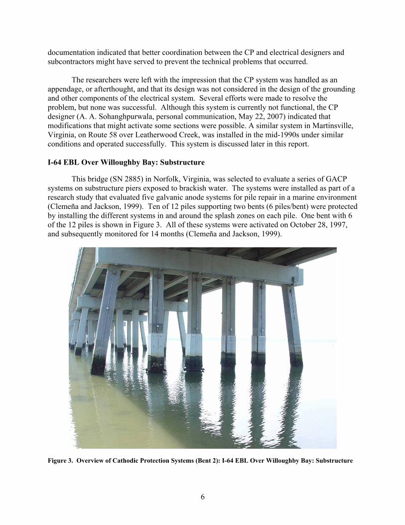
This bridge (SN 2885) in Norfolk, Virginia, was selected to evaluate a series of GACP
systems on substructure piers exposed to brackish water. The systems were installed as part of a research study that evaluated five galvanic anode systems for pile repair in a marine environment (Clemeña and Jackson, 1999). Ten of 12 piles supporting two bents (6 piles/bent) were protected by installing the different systems in and around the splash zones on each pile. One bent with 6 of the 12 piles is shown in Figure 3. All of these systems were activated on October 28, 1997, and subsequently monitored for 14 months (Clemeña and Jackson, 1999).
Figure 3. Overview of Cathodic Protection Systems (Bent 2): I-64 EBL Over Willoughby Bay: Substructure

7
The initial inspection of the control unit for the substructure, shown in Figure 4, quickly revealed that evaluating the structure from this point would be difficult because the wires were numbered and a key to decipher the numbering system was not available. Since the timeline for the current project was limited, the researchers decided that (1) the evaluation should focus on Bent 2 and would include limited electrical measurements, and (2) only the pier jacket systems would be evaluated since they were the only commercially available systems at the time. A visual examination was conducted, and all of the anode systems on Bent 2 were noted to be in good shape, as shown in Figures 3 and 5A and B. Marine life had not appreciably grown under the compression panel (jacket) surface, although this phenomenon has been known to occur in similar installations, resulting in the development of expansive pressure that causes the stainless steel bands to break. The researchers attempted to evaluate the splash zone anodes on Bent 2 by accessing the wiring junction boxes on each pier. By connecting the multimeter directly to the lead wires, as shown in Figure 5C, the researchers attempted to determine the differential voltage and current flow in each system. The lack of connection labels and a wiring diagram made it impossible to determine the exact configuration of the lead wires, and although stable voltage differentials and potentials were observed between the various leads and against an external Cu/CuSO4 (copper-copper sulfate, CSE) half-cell, a reliable determination was not possible. At this time, the researchers believe that at least some of these GACP systems are still functioning.
Figure 4. Control Unit for Substructure Cathodic Protection Systems: I-64 Over Willoughby Bay

8
Figure 5. I-64 EBL Over Willoughby Bay Substructure: (A) No Evidence of Sea Life Build-up Under Compression Panel, (B) Close-up of Structural Jacket Containing Galvanic Cathodic Protection System, (C) Zinc Hydrogel Anode (Upper Pile Region) in Contact with Concrete Surface and All Conduit in Place and Watertight

9
As a point of comparison, the most recent inspection data, dated June 16, 2006, indicated that the substructure condition for the overall structure was “fair” (Williams, 2006). The inspection report also indicated “up to 4-[inch] deep necking along tidal zone exists in twenty piles to fifteen bents,” indicating corrosion damage and loss of cover on some of the unprotected piles.
Based on the researchers’ initial evaluation, a more rigorous survey of these systems,
including the tracing of lead wires and detailed measurements of voltage and current, is recommended as a future activity. If the systems are found to be effective in protecting the piles, similar repairs might be recommended for the deteriorated piles noted by the inspection reports. I-64 EBL Over 13th View Street
This bridge (SN 2882) in Norfolk, Virginia, is a simple-span reinforced-concrete structure located along I-64 between Willoughby Bay and the Hampton Roads Bridge-Tunnel. The structure carries the elevated interstate over a local secondary road on a small peninsula between Willoughby Bay and the Chesapeake Bay, known locally as Willoughby Spit. The CP system on this structure was part of a study by the Federal Highway Administration (FHWA) to evaluate the performance of an ICCP system in a southern marine environment (Swiat and Bushman, 1989). The study evaluated the use of a slotted conductive polymer system on the deck (Zone 1), a zinc coating CP system on the east pier (Zone 2), and a conductive polymer coating system on the west pier (Zone 3), with all three zones connected to the same rectifier/controller (Swiat and Bushman, 1989). The rectifier, shown in Figure 6, was energized on August 1, 1986, and, as part of the study, each zone was subsequently evaluated for 23 months. The report concluded that the system was effectively controlling the corrosion in all three zones during this 23-month period.
The slotted conductive polymer system installed in the deck (see Figure 7) contained
niobium-copper primary anode wires and supplemental secondary anodes of carbon strand, each laid in saw slots 3/8 in to 1/2 in wide by 3/4 in deep and filled with a conductive polymer grout made of vinyl-ester resin and carbon black. A similar system had been installed in 1983 on an inland structure along Route 15 over the Willis River in Buckingham County, Virginia. Within the first 2 years of operation of this type of system on each structure, there was evidence of degradation of the conductive grout caused by acids generated at the anode surfaces (Virmani and Clemeña, 1998). A visual inspection of the deck (Zone 1) indicated discoloration in some areas of the concrete adjacent to the slotted anodes (Swiat and Bushman, 1989). Swait and Bushman (1989) concluded the life of the deck system would be directly related to the time it would take for the system to damage the concrete. Subsequently, Zone 1 of the 13th View Street structure was deactivated.
The system denoted Zone 2, on the east pier, was an arc-sprayed zinc coating comprising
an approximately 20-mil-thick layer of 99% pure zinc applied to the sandblasted concrete surface. Current was supplied to the zinc via titanium distributor bars 1/2 in wide by 4/100 in thick coated with mixed metal oxide (Swiat and Bushman, 1989). Zone 3, on the west pier, was

10
Figure 6. Control Unit for Cathodic Protection System: I-64 EBL Over 13th View Street
Figure 7. Cathodic Protection System on Deck of I-64 EBL Bridge Over 13th View Street

11
a conductive polymer coating 10 to 15 mil thick made of calcined coke breeze in vinyl-ester resin with modifiers. Current was supplied to the coating via platinum wires 0.031 in in diameter (Swiat and Bushman, 1989).
Field observations during this study revealed that alternating current power was still
being supplied to the rectifier, and light-emitting diodes (LEDs) indicated power to the zone circuits. However, the control unit’s internal liquid crystal display (LCD) meter did not function, and attempts to measure voltage or current output at the rectifier using a portable multimeter indicated that no output power was being delivered to the anodes. Interviews with district maintenance personnel suggested that, although the system was left running, regular monitoring of the rectifier was terminated shortly after the completion of the 1989 research report (Swiat and Bushman, 1989). At the present time, the systems on this bridge are not believed to be functioning. The most recent inspection report, dated April 21, 2005 (Williams and Futrell, 2005b), indicated that the overall deck condition was poor, with heavy surface scaling and frequent transverse cracks 1/32 in wide. The substructure pier caps were noted to be in fair condition with minor spalling, and the supporting columns (some previously protected by CP) were in good condition.
Smart Road Bridge Over Route 642
This bridge (SN 1071) in Blacksburg, Virginia, contains an ICCP system designed to
mitigate corrosion in the bridge deck (Figure 8). The most interesting aspect of this research study was that this CP system was installed in a bridge deck while it was being constructed. The system was installed in five zones, with Zone 1 being at the west end of the structure. The system was designed to protect more than 14,000 ft2 of deck through the installation of a titanium ribbon mesh anode with a mixed metal oxide coating embedded in the original cast-in-place concrete. The system incorporated a remote access monitoring system installed with the control system in a bunker at the west end of the bridge (Figure 9), which allows someone to measure the electrical potential and current from a remote location. This system was activated in January 2000 and subsequently monitored for 25 months (Clemeña et al., 2003).
During the study by Clemeña et al. (2003), voltage and current measurements were
periodically gathered using the remote access monitoring system. Recent measurements made during the current study are compared to previous voltage readings in Table 3 and to electrical current values in Table 4, noting the initial rectifier settings, the setting after adjusting the rectifier after 16 months of operation, and the final values reported in 2003. The calculated current density values are given in Table 5. It is clear from Table 3 and the current and current density values in Tables 4 and 5 that the measured voltage values have fluctuated since the rectifier was adjusted in 2001: except for Zone 3, the current density values have decreased between 9% and 70%. Further, Zone 3 indicated that the applied voltage was 0 V, which was due to a missing fuse in the Zone 3 circuit (Figure 9B). Theoretically, a region without an applied cathodic current located adjacent to a protected region in a continuous reinforcement mat, such as in Zone 3, could be at risk for accelerated corrosion. However, Broomfield (2007) reported that accelerated corrosion associated with an unprotected region has not been observed in the field. Nevertheless, this system does require some maintenance and should be checked and adjusted to ensure maximum protection of the structure.

12
Figure 8. Overview of Bridge and Control Bunker: Smart Road Bridge Over Route 642
Figure 9. Impressed Current Cathodic Protection (ICCP) Rectifier System Located in Control Bunker of Smart Road Bridge Over Route 642: (A) Open Bunker Access, (B) Control Panel for 5-Zone ICCP System (Note Missing Fuse for Zone 3) Shows Voltage and Current Display (with Switch on Zone 5)
13
Table 3. Measured Voltage Values (V) Description (Measurement Date) Zone 1 Zone 2 Zone 3 Zone 4 Zone 5
Initial settings (January 5-6, 2000) 1.38 1.38 1.40 2.38 1.72 Rectifier adjustment (approx. 16 months later) 2.43 2.10 3.23 2.70 3.34 Final Clemeña et al. measurement (Feb. 2002) 2.4 2.1 1.9 2.0 2.4 Present study (Feb. 2007) 2.65 2.21 0.00 1.78 2.30 Source: Clemeña et al. (2003).
Table 4. Measured Current Values (A) Description (Measurement Date) Zone 1 Zone 2 Zone 3 Zone 4 Zone 5
Initial settings (January 5-6, 2000) 1.77 2.67 2.00 2.62 2.36 Rectifier adjustment (approx. 16 months later) 2.65 2.74 3.23 2.70 3.34 Final Clemeña et al. measurement (Feb. 2002) 3.1 3.20a 3.3 1.6 3.3 Present study (Feb. 2007) 1.63 1.98 -2.5 0.81 3.04 Source: Clemeña et al. (2003). aClemeña et al. indicated that the value in the graph (0.25 A) was actually around 3.20 A.
Table 5. Calculated Current Densities (mA/m2)
Description (Measurement Date) Zone 1 Zone 2 Zone 3 Zone 4 Zone 5 Initial settings (January 5-6, 2000) 7.02 11.03 5.76 10.83 9.37 Rectifier adjustment (approx. 16 months later) 10.52 11.32 9.31 11.16 13.25 Final Clemeña et al. measurement (Feb. 2002) 12.3 13.2 9.5 6.6 13.1 Present study (Feb. 2007) 6.47 8.18 -7.20 3.35 12.06 Source: Clemeña et al. (2003).
The most recent bridge inspection report, dated September 16, 2005 (Perkins et al. 2005),
indicated the overall deck condition was good. However, there are 1/16-in transverse cracks every 6 to 8 ft starting from the west and traveling east in the first and third spans.
As noted, the system appears to be functioning, with the exception of Zone 3. It does not
appear that regular monitoring of the CP system’s current and voltage output has been documented since the original evaluation period concluded in early 2002. A complete system check and adjustment, as needed, are recommended.
Route 99 Over Peak Creek
This bridge (SN 1039) in Pulaski, Virginia, contains an ICCP system designed to mitigate
corrosion in the existing bridge deck. The deck was divided into six zones (two zones per span) for treatment and monitoring purposes (Fontana et al., 1990). The CP system used a primary and secondary anode design, with a platinum-niobium–coated copper wire functioning as the primary anode and an electrically conductive polymer concrete overlay functioning as a secondary anode to distribute the current evenly over the deck (Fontana et al., 1990). This ICCP system was energized in December 1987 and was routinely monitored during the original study until May 1989 (Fontana et al., 1990).
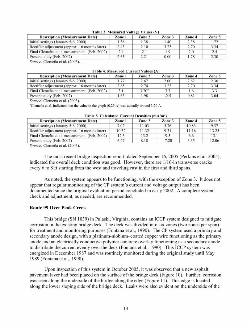
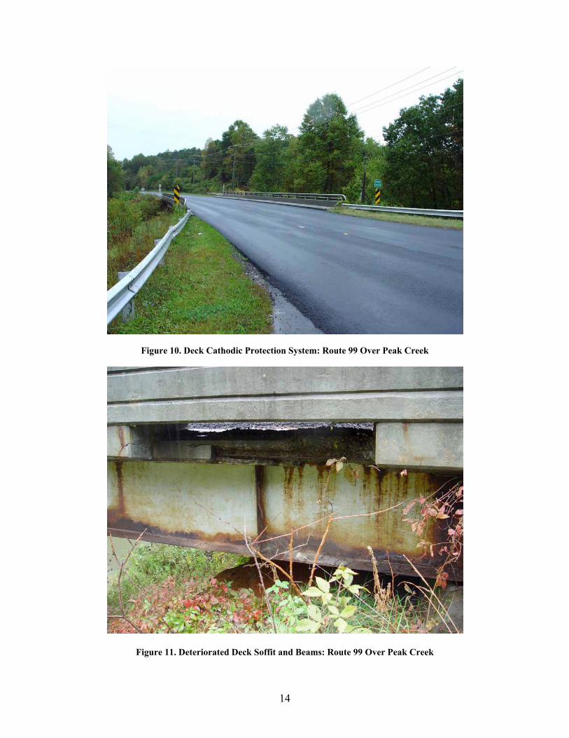
Upon inspection of this system in October 2005, it was observed that a new asphalt
pavement layer had been placed on the surface of the bridge deck (Figure 10). Further, corrosion was seen along the underside of the bridge along the edge (Figure 11). This edge is located along the lower sloping side of the bridge deck. Leaks were also evident on the underside of the
14
Figure 10. Deck Cathodic Protection System: Route 99 Over Peak Creek
Figure 11. Deteriorated Deck Soffit and Beams: Route 99 Over Peak Creek
15
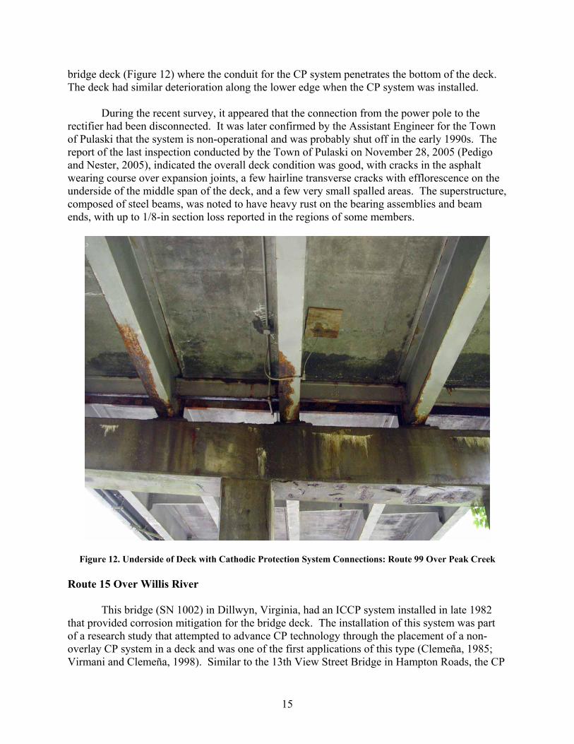
bridge deck (Figure 12) where the conduit for the CP system penetrates the bottom of the deck. The deck had similar deterioration along the lower edge when the CP system was installed.
During the recent survey, it appeared that the connection from the power pole to the rectifier had been disconnected. It was later confirmed by the Assistant Engineer for the Town of Pulaski that the system is non-operational and was probably shut off in the early 1990s. The report of the last inspection conducted by the Town of Pulaski on November 28, 2005 (Pedigo and Nester, 2005), indicated the overall deck condition was good, with cracks in the asphalt wearing course over expansion joints, a few hairline transverse cracks with efflorescence on the underside of the middle span of the deck, and a few very small spalled areas. The superstructure, composed of steel beams, was noted to have heavy rust on the bearing assemblies and beam ends, with up to 1/8-in section loss reported in the regions of some members.
Figure 12. Underside of Deck with Cathodic Protection System Connections: Route 99 Over Peak Creek Route 15 Over Willis River
This bridge (SN 1002) in Dillwyn, Virginia, had an ICCP system installed in late 1982 that provided corrosion mitigation for the bridge deck. The installation of this system was part of a research study that attempted to advance CP technology through the placement of a non-overlay CP system in a deck and was one of the first applications of this type (Clemeña, 1985; Virmani and Clemeña, 1998). Similar to the 13th View Street Bridge in Hampton Roads, the CP

16
system installed to protect this deck comprised platinized-niobium-copper core wire 0.031 in in diameter in transverse slots as the primary anodes. Secondary anodes were pairs of carbon strands 0.00158 in2 laid in longitudinal slots. The slots were 1/2 in wide by 3/4 in deep, filled with conductive polymer concrete. The system was energized in March 1983 and was subsequently monitored for 18 months (Clemeña, 1985).
With regard to the distribution of cathodic current and mitigation of corrosion, at the end
of the study, it was concluded that this form of CP worked to mitigate corrosion (Clemeña, 1985). However, as discussed previously, later observations suggested that acidification of the conductive polymer concrete at the anodes would cause significant maintenance problems, as the fill material would debond and come out of the slots under traffic.
VDOT’s Lynchburg District Structure and Bridge Safety Inspection Engineer reported that the Dillwyn Residency Maintenance Operations Manager indicates that the power to the system was likely disconnected around 1997 to 1998 (J. L. Milton, personal communication, April 20, 2007). The structure was replaced entirely in 2006 (as shown in Figures 13 and 14). The last inspection report prior to replacement, dated January 12, 2005 (Farris and Foster, 2005), confirmed the presence of hairline cracking and scaling over most of the deck surface as well as loose or missing sections of the conductive polymer concrete fill material. The underside of the deck also exhibited scaling, efflorescence, moisture seepage, and some delaminations. The overall deck was considered to be in poor condition.
Figure 13. Deck Cathodic Protection System During Bridge Demolition and Replacement: Route 15 Over Willis River

17
Figure 14. (A) Control Unit and (B) Locked Out Power Meter for Decommissioned Cathodic Protection Deck System: Route 15 Over Willis River I-81 NBL and SBL Over Mill Creek
These bridges (NBL SN 2014, SBL SN 2015) in Mount Jackson, Virginia, received ICCP
systems in 1989 designed to mitigate corrosion in the piers and caps (Clemeña and Jackson, 1997). These are parallel inland structures located over fresh water and a secondary highway, and they are exposed to chlorides during winter because of the use of deicing salts on I-81 (Figure 15). The anodes are an electrically conductive paint system with an embedded platinum-niobium–covered copper wire. The conductive paint shows signs of adhesion failure over approximately 5% to 10% of the surface, as shown in Figure 16.
An experimental remote monitoring system using a conventional telephone modem was
applied to this system. The most recent bridge inspection reports, dated August 24, 2005 (Smoot 2005a,b), indicated that the substructures for both the NBL and SBL structures were in overall good condition except for hairline map cracking in pier caps in the shotcrete repair areas and bleeding of the carbon black of the conductive coating through the surface cosmetic coating layer (Figure 17). The decks were protected by a 1¼-in latex-modified concrete overlay and were reported to be in good condition.
At the present time, there appears to be power supplied to the system, but there are no
records available of routine monitoring. Interviews of district structure and bridge personnel indicated that no one at the district or residency had been acquiring or receiving any sort of status reports on the systems. It is recommended that the system be more closely evaluated to determine if it is functioning and that the status of the remote access monitoring system be ascertained.

18
Figure 15. I-81 SBL Over Mill Creek
Figure 16. Conductive Coating Cathodic Protection System on Substructure of I-81 SBL Over Mill Creek

19
Figure 17. (A) Control Unit and (B) Deteriorated Cathodic Protection Coating on Piers of I-81 SBL Over Mill Creek I-81 NBL and SBL Over Maury River These bridges (NBL SN 2013, SBL SN 2014) in Lexington, Virginia, received ICCP systems in 1992 designed to mitigate corrosion in the piers and caps (as shown in Figure 18) (Clemeña and Jackson, 1997). These bridges were parallel inland structures over fresh water and were exposed to chlorides during the winter because of the use of deicing salts. This system was designed much like the system on I-81 over Mill Creek, and they were installed under the same research initiative. In the final report, Clemeña and Jackson (1997) noted that different contractors performed the work on the two systems and that the installation on this bridge was of lesser quality than that of the Mill Creek system.
Currently, the CP systems on these bridges are out of commission because this section of I-81 is being widened and the bridges are being replaced (see Figure 19). The anodes comprised an electrically conductive paint system with embedded platinum-niobium–covered copper wires. Although the SBL bridge had been demolished and the NBL bridge was scheduled to be demolished, the coating on the NBL substructure could be visually evaluated. The conductive paint showed signs of adhesive failure over approximately 10% to 20% of the surface, with the end caps exhibiting the most significant damage. Overall, it is believed that the substructure system remained in service up until demolition of the host structure began. However, there are not consistent records to indicate that the system was properly monitored or adjusted.

20
Figure 18. (A) Substructure Cathodic Protection Coating System with (B) Coating Adhesion Loss on I-81
NBL Over Maury River
Figure 19. Inspecting Decommissioned Cathodic Protection Control Units: I-81 NBL Over Maury River
21
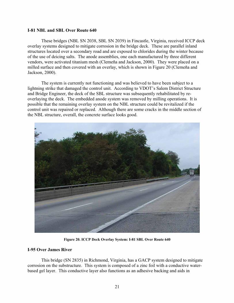
I-81 NBL and SBL Over Route 640 These bridges (NBL SN 2038, SBL SN 2039) in Fincastle, Virginia, received ICCP deck
overlay systems designed to mitigate corrosion in the bridge deck. These are parallel inland structures located over a secondary road and are exposed to chlorides during the winter because of the use of deicing salts. The anode assemblies, one each manufactured by three different vendors, were activated titanium mesh (Clemeña and Jackson, 2000). They were placed on a milled surface and then covered with an overlay, which is shown in Figure 20 (Clemeña and Jackson, 2000).
The system is currently not functioning and was believed to have been subject to a
lightning strike that damaged the control unit. According to VDOT’s Salem District Structure and Bridge Engineer, the deck of the SBL structure was subsequently rehabilitated by re-overlaying the deck. The embedded anode system was removed by milling operations. It is possible that the remaining overlay system on the NBL structure could be revitalized if the control unit was repaired or replaced. Although there are some cracks in the middle section of the NBL structure, overall, the concrete surface looks good.
Figure 20. ICCP Deck Overlay System: I-81 SBL Over Route 640 I-95 Over James River
This bridge (SN 2835) in Richmond, Virginia, has a GACP system designed to mitigate corrosion on the substructure. This system is composed of a zinc foil with a conductive water-based gel layer. This conductive layer also functions as an adhesive backing and aids in

22
attaching the zinc foil to the concrete surface. This system was first evaluated on some of the piles that support the I-64 Bridge over Willoughby Bay in Norfolk, Virginia (Clemeña and Jackson, 1999). The galvanic anode material used on this structure was marketed by the 3M Company as Zinc Hydrogel™, which is no longer available. As may be seen in Figure 21, a significant portion of the anode material is in place; however, metal loss and peeling are evident in some areas.
Figure 21. Zinc Foil Cathodic Protection System on Substructure of I-95 Over James River: (A) Series of Substructure Columns, (B) Typical View of Column And Bent, (C) Close-Up Showing Metal Loss and Peeling of Foil

23
Route 29/Route 250 Over Route 654
The substructure of this bridge (SN 1139) in Charlottesville, Virginia, had GACP installed in two columns as part of a pneumatically applied concrete (shotcrete) repair. Although this is an inland structure, the use of deicing salts in the winter exposes the pier to chlorides in run-off from the roadway above and in water splashed up onto the pier from the road running beneath the bridge. A study by Brown and Sharp (2005) sought to improve the durability and extend the life of shotcrete patch repairs through the use of discrete sacrificial anodes in the columns of Piers P1 and P12, located at the northwest and southeast corners of the structure, respectively. This GACP system was installed in May 2004 and was routinely monitored as part of the study until September 2004 (Brown and Sharp, 2005). Recently, CSE half-cell measurements were made on Column P12, which had required the largest repair. The half-cell results, shown in Figure 22, are overlaid on the measurements shown in the report by Brown and Sharp (2005). The gray area of the plot indicates the area along the circumference that was patched. It is clear that the recent half-cell values are similar to those near the conclusion of the previous study. A hammer was used to determine if delaminations were present adjacent to the patch repairs in Columns P1 and P12. The survey revealed that about 1 ft2 of the concrete had delaminated adjacent to the patch in Column P1 within 3 years after repairs were made. The delamination in Column P1 is located near the bottom of the column (shown in Figure 23) and is oriented approximately 6 in from the nearest anode. It is apparent that this region is not receiving sufficient protection from the anode, although the area remains moist (presumably keeping the resistivity of the concrete lower) and the distance to the closest anode is not great. No delaminations were present in Column P12.
Visible cracks were observed in the patch area on Column P12 (see Figure 24). Based on the crack pattern and the short time after repairs in which they were first observed, these cracks are most likely related to drying shrinkage of the patch material rather than corrosion of the underlying reinforcing steel.
-0.5
-0.4
-0.3
-0.2
-0.1
0.0
0.1
0 1 2 3 4 5 6 7 8 9 10Location
05/20/0405/28/0406/03/0406/10/0409/01/0409/27/0405/20/07P
oten
tial (
V v
s. C
SE
) Patch Area
Figure 22. Column P12 Cu/CuSO4 (CSE) Half-Cell Results: Route 29/Route 250 Over Route 654.

24
Figure 23. Column P1 (A) Prior to Shotcrete and (B) with Subsequent Delamination (hatched area): Route 29/Route 250 Over Route 654
Figure 24. Highlighted Shrinkage Cracks (visible as light lines in grid pattern) in Column P12: Route 29/Route 250 Over Route 654 Route 58 EBL Over Leatherwood Creek
This bridge (SN 1069) in Martinsville, Virginia, is protected by an ICCP deck system and a GACP system on the substructure piers and pier caps. The deck system is approximately 10 years old and uses a titanium mesh overlay system to apply CP to the deck. The most recent
25
inspection report (Maynard and Perkins 2006) indicated that the overall condition of the deck was good, with minor hairline cracking at the top and bottom surfaces of the deck noted.
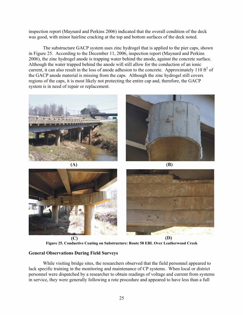
The substructure GACP system uses zinc hydrogel that is applied to the pier caps, shown
in Figure 25. According to the December 11, 2006, inspection report (Maynard and Perkins 2006), the zinc hydrogel anode is trapping water behind the anode, against the concrete surface. Although the water trapped behind the anode will still allow for the conduction of an ionic current, it can also result in the loss of anode adhesion to the concrete. Approximately 110 ft2 of the GACP anode material is missing from the caps. Although the zinc hydrogel still covers regions of the caps, it is most likely not protecting the entire cap and, therefore, the GACP system is in need of repair or replacement.
Figure 25. Conductive Coating on Substructure: Route 58 EBL Over Leatherwood Creek
General Observations During Field Surveys
While visiting bridge sites, the researchers observed that the field personnel appeared to lack specific training in the monitoring and maintenance of CP systems. When local or district personnel were dispatched by a researcher to obtain readings of voltage and current from systems in service, they were generally following a rote procedure and appeared to have less than a full

26
understanding of the electrochemical principles being employed. Interpretation of the reported readings was left to the researcher.
The researchers also could not find evidence of procedures for monitoring and maintaining the CP systems specifically. If a structure contained a CP system, its general visual appearance was often mentioned in biannual structures inspection reports, but no electrical measurements or other assessments specific to CP were carried out, except during the initial study phase in the life of the CP systems. As a rule, once the initial study period was concluded, no clear transfer of responsibility for the CP system maintenance and monitoring occurred. In many cases, it was determined that the VDOT district bridge engineers assumed that the researcher involved in those earlier research studies of CP systems was still providing systematic monitoring of the system.
Further, the researchers found that the documentation of monitoring and maintenance activities was inconsistent. At some locations, full design documents were available. At others, only the original design consultant had that information. In addition, unfortunately, no records of monitoring for the CP systems survived beyond those documented in the initial research reports by the Virginia Transportation Research Council (VTRC). If maintenance had been performed on a particular CP system, it might have been documented in the files for that specific structure, but no central repository appears to exist that tracks the performance of the CP systems Virginia has in service.
Literature Review Galvanic Anode Cathodic Protection
Overview
Zinc and its alloys are the most common type of sacrificial materials that have historically been used in Virginia for GACP systems. For example, these systems were used for the Route 29/Route 250 Bridge over Route 654 and the substructure for the I-64 Bridge over Willoughby Bay. Some of the advantages and limitations of this system are provided in Table 6. Further, AASHTO, ACI, ASTM, and NACE provide guidance through their published standards and recommended practices, a few of which are listed in Table 7.
Table 6. Advantages and Limitations of Galvanic Anode Cathodic Protection Systems Advantage Limitation
Ease of installation Limited current output External power source not required Life limited by quantity and efficiency of anode material for electron
production Low maintenance Source: Virmani and Clemeña (1998).
27
Table 7. Applicable Standards, Recommended Practices, and State-of-the-Art Reports Regarding Galvanic Anode Cathodic Protection Systems
Organization Title Description AASHTO Task Force 29 Report, Guide Specifications for
Cathodic Protection of Concrete Bridge Decks (American Association of State Highway and Transportation Officials, 1994)
Provides standard specification for CP of reinforced concrete
ACI 222.3R, Design and Construction Practices to Mitigate Corrosion of Reinforcement in Concrete Structures (American Concrete Institute, 2003)
Provides summary of materials, history, and design of CP
ACI 222R, Protection of Metals in Concrete Against Corrosion (American Concrete Institute, 2001)
Provides overview of corrosion-related testing and CP
NACE 01105, Sacrificial Cathodic Protection of Reinforced Concrete Elements: A State-of-the-Art Report (NACE International, 2005)
Supplies information on sacrificial systems that are commercially available
NACE Recommended Practice: Sacrificial Cathodic Protection of Reinforcing Steel in Atmospherically Exposed Concrete Structures (Draft) (NACE International, 2007b)
Currently being drafted by NACE Committee TG 047, which is administered by STG 01 on Concrete and Rebar and co-sponsored by STG 05 on Cathodic/Anodic Protection
NACE 01102, State-of-the-Art Report: Criteria for Cathodic Protection of Prestressed Concrete Structures (NACE International, 2002)
Covers strengths and limitations of applying CP to prestressed concrete structures and experiences with different types of galvanic anode CP systems
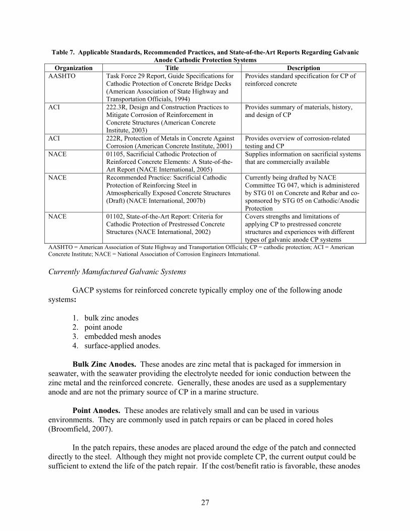
AASHTO = American Association of State Highway and Transportation Officials; CP = cathodic protection; ACI = American Concrete Institute; NACE = National Association of Corrosion Engineers International. Currently Manufactured Galvanic Systems GACP systems for reinforced concrete typically employ one of the following anode systems:
1. bulk zinc anodes 2. point anode 3. embedded mesh anodes 4. surface-applied anodes. Bulk Zinc Anodes. These anodes are zinc metal that is packaged for immersion in
seawater, with the seawater providing the electrolyte needed for ionic conduction between the zinc metal and the reinforced concrete. Generally, these anodes are used as a supplementary anode and are not the primary source of CP in a marine structure.
Point Anodes. These anodes are relatively small and can be used in various
environments. They are commonly used in patch repairs or can be placed in cored holes (Broomfield, 2007).
In the patch repairs, these anodes are placed around the edge of the patch and connected
directly to the steel. Although they might not provide complete CP, the current output could be sufficient to extend the life of the patch repair. If the cost/benefit ratio is favorable, these anodes

28
could provide a useful tool to the bridge owner because of their straightforward methodology and low required maintenance (Brown and Sharp, 2005).
A second application involves coring holes at predetermined locations on the structure.
Anodes are then placed in the core holes, and the holes are filled with mortar. With this type of CP system, the location and number of core holes must be determined and it is probably best suited for an individual familiar with CP design (Broomfield, 2007).
Embedded Mesh Anodes. Anode Jackets. This type of GACP system is designed for piles and columns in the
marine environment. They look similar to other structural fiberglass jacket systems but have zinc mesh inside the fiberglass jacket, which provides much-needed CP to the steel. The reason the zinc mesh is important is that saltwater wicks upward and exacerbates corrosion inside the fiberglass jacket and the jacket obscures the corrosion until removed (Hartt and Rapa, 1998). Significant reinforcement section loss could occur in such instances.
In addition to the testing in Virginia (Clemeña and Jackson, 1999), these anodes were
tested by the Florida Department of Transportation (FDOT). In the FDOT test, the researchers (Kessler et al., 1991, 1996) reached the same conclusion reached in the Virginia study that the anode jackets provided favorable restoration and corrosion mitigation results.
Galvanic Anode Overlay. Recently, research on a galvanic anode intended for placement in an overlay has shown promise (C. Firlotte, personal communication, March 28, 2007). The Missouri Department of Transportation is currently conducting an experimental field application on a bridge deck in Missouri. This system is similar to an impressed overlay system, but it does not require a rectifier or the power utility requirements.
Surface Applied Anodes. Thermal Spray Zinc. Commercially pure zinc can be applied by thermally spraying zinc
in a manner analogous to that of spraying paint; however, the equipment is more cumbersome and some protection is required for the operator because of the molten state of the zinc. In marine environments, zinc can be used alone, and if a humectant solution is applied, the use of zinc can be expanded to include less humid environments (Broomfield, 2007).
Thermal Spray Aluminum/Zinc/Indium. Corrpro Companies, Inc., developed this
proprietary material, which is sold as CorrsprayTM, through a contract with FHWA (Corrpro Companies Inc., 2003; Daily and Green, 2007). The anode is composed of approximately 20% zinc, 0.2% indium, and the balance aluminum (Corrpro Companies Inc., 2003; Daily and Green, 2007). The indium acts as an activating agent.

29
Impressed Current Cathodic Protection Overview
Historically, the majority of CP systems in Virginia have been ICCP systems. For these
systems, the anode materials have primarily included the following three designs:
1. platinum-niobium–covered copper wire embedded in conductive polymer grout 2. platinum-niobium–covered copper wire embedded in a conductive paint 3. mixed metal oxide–coated titanium mesh anodes.
The platinum-niobium–covered copper wire system was initially deemed to be a fairly
effective CP system that could be easily installed with minimal disruption to traffic (Virmani and Clemeña, 1998). Initial concerns that this system might expose bars during the slot cutting installation became irrelevant once it was learned that acid production at the anode during operation damaged the grout (Virmani and Clemeña, 1998). Therefore, the use and operation of this type of system in Virginia were discontinued.
The platinum-niobium–covered copper wire (or other inert conductor) embedded in a
conductive paint system, along with mixed metal oxide–coated titanium mesh anodes, continues to be used (Broomfield, 2007). Some advantages and limitations of these types of ICCP systems are provided in Table 8. Further, AASHTO, ACI, ASTM, and NACE provide guidance through their published standards and recommended practices, a few of which are listed in Table 9.
Table 8. Advantages and Limitations of Impressed Current Cathodic Protection Systems
Advantage Limitation Adjustable voltage/current output Routine monitoring and maintenance required Can be designed to mitigate corrosion in most structures/environments.
Can have interference between ICCP and other electrical systems
Could potentially provide corrosion mitigation for life of structure
Source: Virmani and Clemeña (1998). Currently Manufactured Impressed Systems
Two major components of impressed current systems are anodes and rectifiers, each of
which may be one of several types. Anodes.
Conductive Coating. Conductive coatings are composed of a conductive medium in an organic binder. This type of anode can generally be applied successfully on surfaces where a standard coating could also be applied but CP is needed instead. As with many coating systems, poor surface preparation, highly moist environments, or abrasion can substantially reduce the life of the conductive coatings. Although these coating systems were initially solvent-based systems, it is reported that newer water-based coatings are currently available (Broomfield, 2007).

30
Table 9. Applicable Protection Standards, Recommended Practices, and State-of-the-Art Reports for Impressed Current Cathodic Protection Systems
Organization Title Description
AASHTO Task Force 29 Report, Guide Specifications for Cathodic Protection of Concrete Bridge Decks (American Association of State Highway and Transportation Officials, 1994)
Provides standard specification for CP of reinforced concrete
ACI 222.3R, Design and Construction Practices to Mitigate Corrosion of Reinforcement in Concrete Structures (American Concrete Institute, 2003)
Provides summary of materials, history, and design of CP
ACI 222R, Protection of Metals in Concrete Against Corrosion (American Concrete Institute, 2001)
Provides overview of corrosion-related testing and CP operating parameters and options using ICCP
NACE RP0290, Impressed Current Cathodic Protection of Reinforcing Steel in Atmospherically Exposed Concrete Structures (NACE International, 2007a)
Provides guidance for ICCP corrosion control in atmospherically exposed reinforced concrete
NACE 01102, State-of-the-Art Report: Criteria for Cathodic Protection of Prestressed Concrete Structures (NACE International, 2002)
Covers strengths and limitations of applying CP to prestressed concrete structures and experiences with different types of impressed current CP systems
AASHTO = American Association of State Highway and Transportation Officials; CP = cathodic protection; ACI = American Concrete Institute; NACE = National Association of Corrosion Engineer. Coated Titanium Mesh. Coated titanium has been used as an anode in both expanded mesh and mesh ribbon forms. The coating on the anode helps improve the efficiency of the anode for CP applications in reinforced concrete structures. These anodes are then placed in grout or overlaid with concrete and, therefore, can be used on wearing surfaces.
Rectifiers. Standard Rectifiers. The standard rectifier converts an alternating current power source
to direct current power while controlling the amount of current supplied to the steel. These rectifiers have been available for decades in other fields such as the petroleum and shipping industries and some utility systems (Jones, 1996). Since they are often exposed to outdoor environments, these systems are built to be rugged but do require routine maintenance to ensure proper operation.
Remote Monitoring Rectifiers. To reduce the number of times a rectifier must be
personally inspected, remote monitoring systems (RMS) were developed. An RMS attaches to a rectifier and provides data from the remote CP location. Although these systems can gather and transmit data, it is still important to check the rectifier and RMS routinely to ensure that both are operating properly. Further, the RMS can only gather and transmit data, so adjustments must be made at the rectifier.
Remote Monitoring and Control Rectifiers. Recently, a greater degree of control over a
remote rectifier has become possible through the use of advanced communications and control

31
circuitry, allowing the use of electronic devices that remotely monitor and control the rectifier. As with the RMS, it is still important to check the rectifier, monitoring, and control systems routinely.
Monitoring by Other Agencies of Cathodic Protection Systems in Reinforced Concrete
Because of the highly corrosive environment to which reinforced concrete structures are
subjected in Florida, FDOT has developed a group of experts that include FDOT personnel and faculty of Florida universities. One of the focus areas of this group is the development, installation, and monitoring of CP systems (Hartt and Chu, 2007; Kessler et al., 2006; Powers et al., 2001; Simmons et al., 2005). They have been responsible for advancements in the use of CP technology, including the commonly used GACP structural jacket systems. Other DOTs also have key personnel that are knowledgeable in CP technology to provide guidance when needed (Bullard et al., 2007; Cryer, 2006).
The U.S. Department of the Interior, Bureau of Reclamation, also has a group of experts on CP of steel in concrete (D. A. Little, personal communication, May 2007). These individuals can provide help in CP design, installation, monitoring, and troubleshooting. As a point of comparison, the total present day cost to have such an expert evaluate a CP system in Virginia for 2 days and submit a report would be approximately $10,000 (D. A. Little, personal communication, May 2007). It is important to note that such costs include travel from Colorado and would be slightly lower if additional CP systems were evaluated during the same trip.
Private consultants can also be employed to monitor and maintain ICCP systems. Generally, NACE recommends each system be inspected annually (NACE International, 2007a). For a relatively small system under routine monitoring, an inspection by a CP consultant may cost on the order of $1,500 to $3,000 per visit, depending on whether the field visit is conducted by a trained CP technician or by a CP specialist (A. A. Sohanghpurwala, personal communication, May 22, 2007). Costs are dependent upon travel and per diem costs, desired detail and complexity of the final report, and the size of the system being inspected. A large structure with many CP zones may take several days to inspect (A. A. Sohanghpurwala, personal communication, May 22, 2007).
More comprehensive system evaluations are often conducted by private consultants based
on a daily rate, which costs on the order of $1,200 per day for a CP technician or $2,500 per day for a CP specialist (A. A. Sohanghpurwala, personal communication, May 22, 2007). For a CP system on even a small structure, such an evaluation may take 2 to 3 days of field work to complete. Additional time would be required for analysis and reporting (A. A. Sohanghpurwala, personal communication, May 22, 2007).
RMS can improve the frequency and consistency of monitoring while potentially
decreasing the overall cost of routine monitoring. Monthly reporting by a CP consultant on a CP system with RMS can be provided for about $200 per month (A. A. Sohanghpurwala, personal communication, May 22, 2007). More frequent monitoring via RMS can provide a more timely response in the case of a component failure and reduce downtime for the system (A. A. Sohanghpurwala, personal communication, May 22, 2007).
32
CONCLUSIONS
• Although CP systems deployed in concert with VTRC research studies remained in service, the researchers found little evidence that the transfer of the responsibility for maintenance and monitoring of those systems to the appropriate VDOT field personnel has occurred. As a result, little information has been gathered regarding the performance of these systems beyond the initial evaluations during the research studies. In addition, this led to little or no maintenance of CP systems being conducted at these sites.
• VDOT’s bridge inspection reports were found to include only minimal information about the
status of the ICCP systems in place on the structures evaluated in the field survey. It appears that visual observations have been made about the outward appearance of the systems. However, there is no record of electrical measurements being made to confirm the operational status of these systems and that sufficient cathodic current has been applied to ensure protection of the structure(s).
• To date, there is a lack of training offered to VDOT bridge inspection personnel that will
equip them to provide adequate monitoring and maintenance of CP systems. As a result, VDOT has little or no expert staff available to monitor or review its CP systems. State DOTs that report successful CP programs have personnel available who are knowledgeable about CP systems for steel in concrete.
• Research on some GACP systems (e.g., GACP structural jackets and thermally sprayed
GACP systems) has demonstrated favorable results. This technology has not yet been commonly deployed in the field in Virginia structures. The literature review in this study indicated that GACP systems enhance the service life of reinforced concrete structures or components and require less monitoring and maintenance than do their ICCP counterparts.
• A CP system installed in VDOT’s Hampton Roads District in a non-research application was
not successful. The researchers suspect this was because the relatively large system constituted the first CP treatment of a structure in Virginia that was not part of a research study and thus was not deployed under the tightly controlled conditions of a research study. As CP systems in non-research applications become common, and they are thus treated as an integral part of the structure with the concurrent ordinary maintenance, greater successes will likely accrue.
RECOMMENDATIONS
1. VTRC and VDOT’s Structure & Bridge Division should conduct more in-depth follow-up studies of the Virginia CP systems identified herein as being still in service or potentially in service. Further, the current output of ICCP systems should be measured for each zone/component and adjusted as necessary to provide continued protection.
2. VDOT’s Structure & Bridge Division should establish a protocol for the selection and use of
CP systems in Virginia. Such a protocol should include guidance in the selection of ICCP
33
versus GACP. Further, so that VDOT may use CP technology to its best advantage, CP systems should be employed more frequently and the technology incorporated into routine agency design and maintenance practice.
3. To ensure successful installation of future CP systems, VDOT’s Structure & Bridge Division
should promote adequate communication between design consultants and subconsultants, and with construction contractors and subcontractors. Adequate authority should be granted to members of the design and construction team who have expertise in CP. It is important that the CP system not be treated as a stand-alone appendage but rather be considered in conjunction with the other electrical systems on a structure.
4. VDOT’s Structure & Bridge Division should establish procedures and personnel, either in a
centralized in-house group or as external contracts, to perform routine maintenance on CP systems that are in service. Further, a protocol should be established for CP inspection data storage and review.
5. VTRC and VDOT’s Structure & Bridge Division should consider evaluating the defunct
system on the Hampton Roads Bridge-Tunnel to determine the cause of failure and potentially salvage all or part of the system.
6. VTRC should evaluate the potential effectiveness of remote monitoring systems and remote
monitoring and control systems for new and existing ICCP systems. 7. VDOT’s Structure & Bridge Division should investigate the efficacy and cost of retrofitting
existing CP systems with remote monitoring systems and remote monitoring and control systems to simplify monitoring or maintenance activities on ICCP systems.
COSTS AND BENEFITS ASSESSMENT
To rehabilitate a three-span, 150-ft-long structure carrying two lanes of traffic, a latex-
modified overlay can be applied for approximately $10.25 per square foot (using VDOT project costs from 2006). Such an overlay could be expected to extend the life of the deck by about 18.5 years (Koch et al., 2002). The deck could be further protected with an ICCP system at $13 per square foot (not including the cost of repairs and overlay) for approximately $70,000 additional cost (Koch et al., 2002). The ICCP system would be expected to extend the life benefit of the overlay to 35 years if properly maintained (Koch et al., 2002). By contrast, if the ICCP system is not installed, rehabilitation after approximately 18 years would cost approximately $110,000 in 2007 dollars (based on current VDOT project costs). By nearly doubling the life of the deck repairs and overlay, the ICCP system can prevent the occurrence of another such rehabilitation in the future. Even with routine monitoring of the ICCP system, at the cost difference of approximately $40,000 over the same 18-year period, the CP system can provide substantial savings. The direct costs of the two approaches, with or without a CP system, are similar over the life of the deck. However, this simple analysis does not take into consideration the user costs associated with the closing of a structure for rehabilitative repair. By preserving the structure

34
and extending the life of the initial overlay with a CP system, a future rehabilitation can be deferred or prevented and fewer intermediate repairs will be necessary. This can have significant implications for users of a structure, particularly on congested urban or arterial routes.
The substructure of such a bridge with two four-pier bents might receive an Al-Zn-In
alloy thermal spray GACP system. The cost of this application would be on the order of $12 per square foot, for a total of approximately $24,000 in addition to the cost of any necessary repairs (Koch et al., 2002). The GACP system is expected to last 15 years on average, depending on the severity of exposure (Koch et al., 2002). Substructure repairs cost on the order of $75 per square foot (based on current VDOT project costs). A GACP system would break even in cost if it could prevent the need for repairs on approximately 16% of a substructure surface over the life of the structure. Further, this sort of system does not require a significant investment in monitoring or maintenance, thereby reducing long-term costs.
ACKNOWLEDGMENTS The authors are grateful for the cooperation given by VDOT district structure and bridge
personnel, who provided valuable documentation and historic information concerning the systems discussed in this report.
Tim Felton and Jack Meredith of VDOT’s Hampton Roads District, Danny Torrence and
Jeff Milton of VDOT’s Lynchburg District, Nancey Widgen-Woodson and Dean Hackett of VDOT’s Salem District, Park Thompson of VDOT’s Staunton District, and David Pearce of VDOT’s Culpeper District all provided valuable information concerning the structures in their districts. Thanks go also to Riki Williams and Brian Futrell of VDOT’s Hampton Roads District, who provided access and assistance while testing the Willoughby Bay substructure. The authors appreciate the cooperation of Scott Stone, Cindy Wilkinson, and the staff of the Virginia Tech Transportation Institute with regard to access and information concerning the system installed on Virginia’s Smart Road.
Interviews with Doug Leng of Corrosion Restoration Technologies, Tequesta, FL, and
Ali Sohanghpurwala of ConCorr, Inc., Sterling, VA, proved very helpful, and their support is appreciated. The authors also appreciate the valuable information provided by Clem Firlotte of Corrpro, Corp., Medina, OH.
Finally, the authors acknowledge the efforts of Rick Childs of VTRC in retaining samples
and conducting field tests.
REFERENCES
American Association of State Highway and Transportation Officials, AASHTO-AGC-ARTBA Joint Cooperation Committee, Subcommittee on New Highway Materials, Task Force 29. Guide Specification for Cathodic Protection of Concrete Bridge Decks. Washington, DC, 1994.
35
American Concrete Institute, Committee 222–Corrosion of Metals in Concrete. Protection of Metals in Concrete Against Corrosion. Report No. ACI 222R-01. Farmington Hills, MI, 2001.
American Concrete Institute, Committee 222–Corrosion of Metals in Concrete. Design and Construction Practices to Mitigate Corrosion of Reinforcement in Concrete Structures. Report No. ACI 222.3R-03. Farmington Hills, MI, 2003.
Broomfield, J. P. Corrosion of Steel in Concrete: Understanding, Investigation and Repair. Taylor & Francis, London, 2007.
Brown, M.C., and Sharp, S.R. Effectiveness of Sacrificial Anodes in High-Resistivity Shotcrete Repairs. VTRC 05-R25. Virginia Transportation Research Council, Charlottesville, 2005.
Bullard, S.J., Covino Jr., B.S., Williamson, K.M., Holcomb, G.R., Ziomek-Moroz, M., and Cryer, C.B. Field Trial of ICCP, SACP, CVCP, and ICP on a Steel Reinforced Coastal Bridge. In NACE Corrosion 2007, NACE International, Nashville, TN, 2007.
Clemeña, G.G. A Slotted Cathodic Protection System for Bridge Decks. VHTRC 85-R27. Virginia Highway & Transportation Research Council, Charlottesville, 1985.
Clemeña, G.G., and Jackson, D.R. Performance of a Conductive-Paint Anode in Cathodic Protection Systems for Inland Concrete Bridge Piers in Virginia. FHWA/VTRC 98-R7. Virginia Transportation Research Council, Charlottesville, 1997.
Clemeña, G.C., and Jackson, D.R. Evaluation of Anodes for Galvanic Cathodic Prevention of Steel Corrosion in Prestressed Concrete Piles in Marine Environments in Virginia. VTRC 00-R3. Virginia Transportation Research Council, Charlottesville, 1999.
Clemeña, G.G., and Jackson, D.R. Cathodic Protection of Concrete Bridge Decks Using Titanium-Mesh Anodes. VTRC 00-R14. Virginia Transportation Research Council, Charlottesville, 2000.
Clemeña, G.G., Pritchett, M.B., and Napier, C.S. Application of Cathodic Prevention in a New Concrete Bridge Deck in Virginia. VTRC 03-R11. Virginia Transportation Research Council, Charlottesville, 2003.
Corrpro Companies Inc. CorrsprayTM Product Brochure. Medina, OH, 2003.
Cryer, C.B. Using Cathodic Protection to Preserve Historic Concrete Bridges. Paper presented at the 2006 Concrete Bridge Conference, Reno, Nevada, May 7-9, 2006.
Daily, S.F., and Green, W.K. Galvanic Cathodic Protection of Reinforced and Prestressed Concrete Structures Using CorrsprayTM—A Thermally Sprayed Aluminum Alloy. Technical Paper 51. Corrpro Companies Inc., Medina, OH, 2005. http://www.corrpro.com/pdf/CP51-CORRSPRAY.pdf. Accessed May 21, 2007.

36
Farris, R.A., and Foster, M.P., Jr. Structure Inspection Report—Summary: S. James Madison Highway Over Willis River—Agency ID 0141002. Virginia Department of Transportation, Lynchburg, January 12, 2005.
Fontana, J.J., Reams, W., Scannell, W., and Sprinkel, M. Electrically Conductive Polymer Concrete Overlay as Secondary Anode for Cathodic Protection. FHWA-RD-90-005. Federal Highway Administration, Turner-Fairbank Highway Research Center, McLean, VA, 1990.
Hartt, W.H. and Rapa, M. Condition Assessment of Jackets Upon Pilings for Florida Bridge Substructures. Final Report, WPI No. 0510803. Florida Department of Transportation, Tallahassee, April 13, 1998.
Hartt, W.H., and Chu, W. Utility of Submerged Bulk Galvanic Anodes for Above-Waterline Reinforced Concrete Elements. NACE Corrosion 2007, NACE International, Nashville, TN, 2007.
Jones, D.A. Principles and Prevention of Corrosion. Prentice Hall, Upper Saddle River, NJ, 1996.
Kessler, R.J., Powers, R.G., and Lasa, I.R. Cathodic Protection Using Scrap and Recycled Materials. Materials Performance, Vol. 30, No. 6, June 1991, pp. 29-31.
Kessler, R.J., Powers, R.G, and Lasa, I.R. Zinc Mesh Anodes Cast into Concrete Pile Jackets. Materials Performance, Vol. 35, No. 12, December 1996, pp. 11-15.
Kessler, R.J., Powers, R.G, and Lasa, I.R. Case Studies of Impressed Current Cathodic Protection Systems for Marine Reinforced Concrete Structures in Florida. In NACE Corrosion 2006, NACE International, San Diego, CA, 2006.
Koch, G.H., Brongers, M.P.H., Thompson, N.G., Virmani, Y.P., and Payer, J.H. Corrosion Cost and Preventive Strategies in the United States. FHWA-RD-01-156. Federal Highway Administration, Turner-Fairbank Highway Research Center, McLean, VA, 2002.
Maynard, K., and Perkins, D. Structure Inspection Report: Route 58 EBL Business Over Leatherwood Creek—Agency ID 0441069. Virginia Department of Transportation, Salem, December 11, 2006.
NACE International, Task Group 44–Reinforced Concrete. Standard Practice—Impressed Current Cathodic Protection of Reinforcing Steel in Atmospherically Exposed Concrete Structures. No. SP0290-2007. Houston, TX, March 12, 2007a.
NACE International, Task Group 46–Cathodic Protection of Prestressed Concrete Elements. State-of-the-Art Report: Criteria for Cathodic Protection of Prestressed Concrete Structures. NACE 01102-2002. Houston, TX, 2002.

37
NACE International, Task Group 47–Concrete and Rebar. Sacrificial Cathodic Protection of Reinforced Concrete Elements: A State-of-the-Art Report. NACE 01105-2005. Houston, TX, 2005.
NACE International, Task Group 47–Concrete and Rebar. Sacrificial Cathodic Protection of Reinforcing Steel in Atmospherically Exposed Concrete Structures (Draft). Houston, TX, 2007b.
Pedigo, W.D., and Nester, T.M. Bridge Inspection Report: Rt. 99 Over Peak Creek—Bridge No. 1039. City of Pulaski, Pulaski, VA, November 28, 2005.
Perkins, D., Maynard, K., and Meadows, S. Structure Inspection Report: Smart Road Over Rte. 642—Agency ID 0601071. Virginia Department of Transportation, Salem, September 16, 2005.
Powers, R.G., Lasa, I.R., and Duncan, M.H. Case Studies of Impressed Current Cathodic Protection Systems for Marine Reinforced Concrete Structures in Florida. 01-01A. Florida Department of Transportation, Tallahassee, 2001.
Simmons, R.M., Lasa, I.R., Powers, R.G, and Sagues, A.A. Evaluation of Remotely Monitored Battery Powered Systems for Cathodic Protection of Reinforced Concrete. BC353-45. Florida Department of Transportation, Tallahassee, 2005.
Smoot, W. Structure Inspection Report—Summary: I-81 NBL Over Mill Creek, Rt 263 and Rt 698—Agency ID 0852014. Virginia Department of Transportation, Staunton, August 24, 2005a.
Smoot, W. Structure Inspection Report-Summary: I-81 SBL Over Mill Creek, Rt 263 and Rt 698—Agency ID 0852015. Virginia Department of Transportation, Staunton, August 24, 2005b.
Swiat, W.J., and Bushman, J.B. Further Improvements in Cathodic Protection. FHWA-RD-88-267. Federal Highway Administration, Turner-Fairbank Highway Research Center, McLean, VA, 1989.
Virmani, Y.P., and Clemeña, G.G. Corrosion Protection: Concrete Bridges. FHWA-RD-98-088. Federal Highway Administration, Turner-Fairbank Highway Research Center, McLean, VA, 1998.Williams, R.E. Structure Inspection Report—Summary: I-64 Over Willoughby Bay—Agency ID 1222885. Virginia Department of Transportation, Suffolk, June 16, 2006.
Williams, R.E., and Futrell, B.K. Structure Inspection Report—Commentary: North Approach Trestle to Hampton Roads Tunnel—Agency ID 1142902. Virginia Department of Transportation, Suffolk, August 12, 2005a.
Williams, R.E., and Futrell, B.K. Structure Inspection Report-Commentary: IS-64 Over 13th View Street—Agency ID 1222882. Virginia Department of Transportation, Suffolk, April 21, 2005b.