virtra range™ · pdf filethis company makes no representations or warranties regarding...
TRANSCRIPT

VIRTRA RANGE™ INSTRUCTIONS
© 2012 by VirTra Inc. All Rights Reserved. VirTra, the VirTra logo are either registered trademarks or trademarks of VirTra in the
United States and/or other countries.
Version 1.0-1012
Author:
Robbie Dowling
COPYRIGHT
Copyright © 2012 by VirTra Inc. All Rights Reserved. No part of this publication may be reproduced, transcribed, stored in a retrieval system, translated into any language, or transmitted in any form or by any means, electronic, mechanical, magnetic, optical, chemical, photocopying, manual, or otherwise, without prior written permission from VirTra Inc.
DISCLAIMER
VirTra Inc. shall not be liable for any incidental or consequential damage resulting from the performance or use of this product. This company makes no representations or warranties regarding the contents of this manual. Information in this manual has been carefully checked for reliability; however, no guarantee is given as to the correctness of the contents. In the interest of continued product improvement, this company reserves the right to revise the manual or include changes in the specifications of the product described within it at any time without notice and without obligation to notify any person of such revision or changes. The information contained in this manual is provided for general use by the customers of the product.
TRADEMARKS
VirTra Range™ (Patent Pending) is a trademark of VirTra Inc. Product names used in this manual are ascribed to their respective owners and acknowledged.

TABLE OF CONTENTS
I. VIRTRA VRANGE CPU SETUP 4
1.1 VIRTRA RANGE CONTROL FROM THE TABLET 4
1.2 RUNNING THE VIRTRA RANGE 10
1.3 ZEROING A WEAPON 14
II. CONFIGURING THE PROJECTOR 15
2.1 PLACEMENT 15
2.2 FOCUS/ALIGNMENT IMAGE 16
III. CONFIGURING THE BASLER CAMERA 17
3.1 SYSTEM CALIBRATION 17
3.2 SETTING UP THE CAMERAS 17
3.3 POWER UP 17
Step 1 - Connect 18
Step 2 - Dead Pixel Scan 20
Step 3 - Focus and Alignment * No Image 21
Step 4 - AOI (Area of Interest) 22
Step 5 - Automatic Calibration 23
IV. CONTACT VIRTRA 29

PAGE 4VRANGE™ INSTRUCTION MANUAL
TABLE OF CONTENTS
I. VIRTRA VRANGE CPU SETUP
1.1 VIRTRA RANGE CONTROL FROM THE TABLET
1. With everything off, power on the VirTra Range tablet.
2. Double Click on the “VirTra Range Control” icon.
Figure 1 - Tablet Desktop

PAGE 4 PAGE 5VRANGE™ INSTRUCTION MANUAL
TABLE OF CONTENTS
Figure 2 – Virtra Range Control Main
3. If there are multiple ranges, like the two shown above, highlight the appropriate range.
4. Power on the range cpu by clicking on the green button under computer
5. Power on the projector by clicking on the green button under the projector
6. If the range has not been previously calibrated, press the Calibrate Range button and follow the in-structions outlined in Chapter ##.
7. If the firearm being used has not been used on this range or disassembled for maintenance, press the
“Zero Firearm” button and follow the instruction outlined in Section 1.3.
PAGE 6VRANGE™ INSTRUCTION MANUAL
TABLE OF CONTENTS
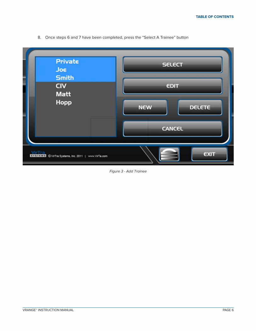
8. Once steps 6 and 7 have been completed, press the “Select A Trainee” button
Figure 3 - Add Trainee
PAGE 6 PAGE 7VRANGE™ INSTRUCTION MANUAL
TABLE OF CONTENTS
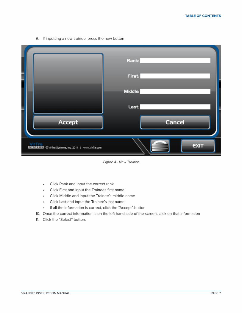
9. If inputting a new trainee, press the new button
• Click Rank and input the correct rank
• Click First and input the Trainees first name
• Click Middle and input the Trainee’s middle name
• Click Last and input the Trainee’s last name
• If all the information is correct, click the “Accept” button
10. Once the correct information is on the left hand side of the screen, click on that information
11. Click the “Select” button.
Figure 4 - New Trainee

PAGE 8VRANGE™ INSTRUCTION MANUAL
TABLE OF CONTENTS
12. Press the “Select A Weapon” button.
Figure 5 - Add Weapon

PAGE 8 PAGE 9VRANGE™ INSTRUCTION MANUAL
TABLE OF CONTENTS
13. If inputting a new Weapon, press the new button.
• Click “Model” and input the correct model of firearm• Click the blank area for “Serial #” and input the weapon’s serial number• Click the button for “Laser ID” and select the appropriate laser number associated with the Virtra
recoil kit.• If all the information is correct, click the “Accept” button
14. Once the correct information is on the left hand side of the screen, click on that information
15. Click the “Select” button.
16. Once all the above steps are completed, press the “Start Range button”

PAGE 10VRANGE™ INSTRUCTION MANUAL
TABLE OF CONTENTS
1.2 RUNNING THE VIRTRA RANGE
1. Using the button box, choose the target, course and background by pressing the buttons on the button box.

PAGE 10 PAGE 11VRANGE™ INSTRUCTION MANUAL
TABLE OF CONTENTS
2. Using the button box from the first screen, pressing the menu button once will let you choose either indoor scenery or outdoor scenery.
PAGE 12VRANGE™ INSTRUCTION MANUAL
TABLE OF CONTENTS
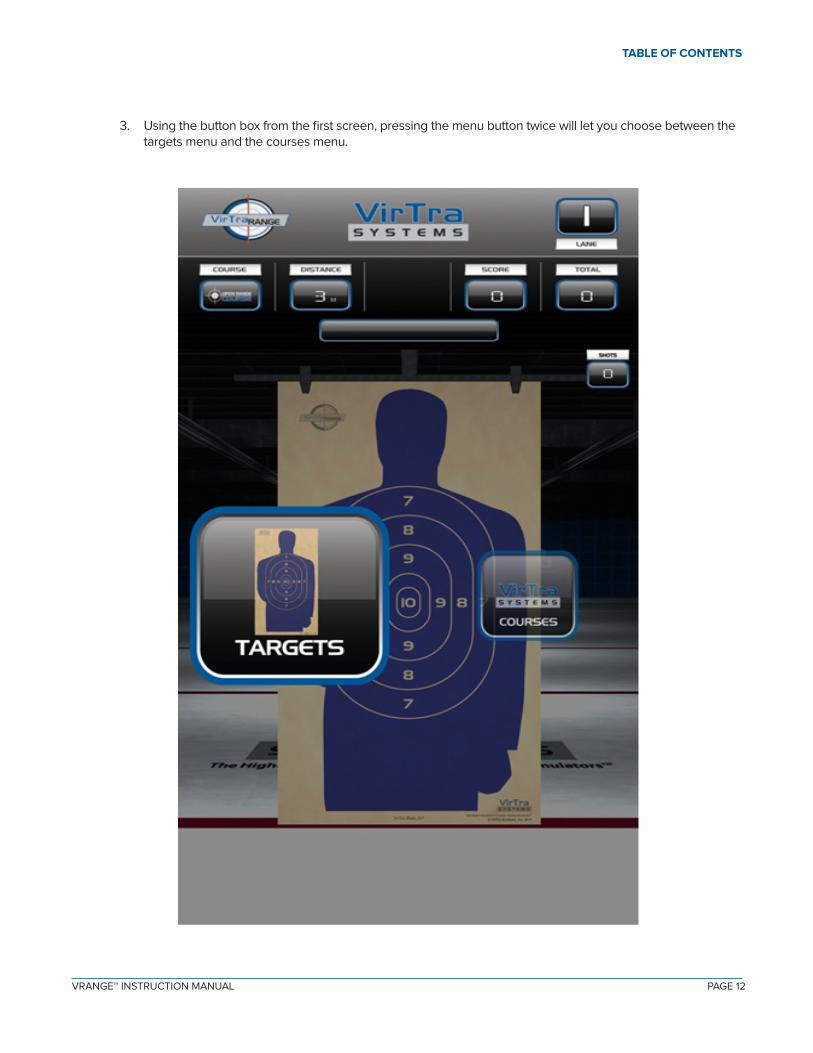
3. Using the button box from the first screen, pressing the menu button twice will let you choose between the targets menu and the courses menu.

PAGE 12 PAGE 13VRANGE™ INSTRUCTION MANUAL
TABLE OF CONTENTS
4. Once you have chosen your location, target, and course, you are ready to begin shooting.
5. Pressing the left or right arrows will move the target forward or back respectively.6. Pressing the zoom button will take the target from whatever distance and make is close for the purpose of
reviewing shots. NOTE: You cannot shoot target in “Zoom Mode”
7. Pressing the menu button will give you the options to change the location, target and course.8. Pressing the clear button will remove all the bullet holes from the target.

PAGE 14VRANGE™ INSTRUCTION MANUAL
TABLE OF CONTENTS
1.3 ZEROING A WEAPON
Click on the “Zero Firearm” button. A target will appear on the middle of the screen, and be in-structed to fire 3 rounds at the target as accurately as possible. This “dials in” the difference between the trainee’s sight picture and the laser striking the screen. This process can be cancelled if neces-sary by clicking ”STOP ALL” on the tablet while the process is running. This process needs to be done each time a weapon is added and should be done for each new user of that weapon.
FIre 3 Shots at the center of the target!

PAGE 14 PAGE 15VRANGE™ INSTRUCTION MANUAL
TABLE OF CONTENTS
II. CONFIGURING THE PROJECTOR
The VirTra Range is equipped with a projector used to project the target on the screen. The projector should be pointed at the screen and aligned to fill the entire screen. Carefully follow the instructions below to properly align the projector. Proper alignment of the projector will create a seamless training environment. Proper alignment also increases the emersion for the trainee into the simulated environment.
Ensure the computer is powered on before aligning the projector.
2.1 PLACEMENT
Place projector on the floor in front of the intended screen and power on the projector.
Ensure all video and network cables are correctly connected to the rear of the projector.
Figure 3.0.1 - Projection placement
PAGE 16VRANGE™ INSTRUCTION MANUAL
TABLE OF CONTENTS
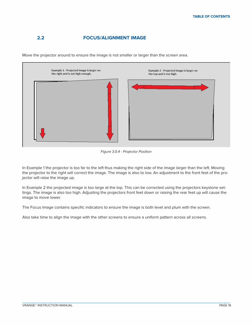
Move the projector around to ensure the image is not smaller or larger than the screen area.
2.2 FOCUS/ALIGNMENT IMAGE
Figure 3.0.4 - Projector Position
In Example 1 the projector is too far to the left thus making the right side of the image larger than the left. Moving the projector to the right will correct the image. The image is also to low. An adjustment to the front feet of the pro-jector will raise the image up.
In Example 2 the projected image is too large at the top. This can be corrected using the projectors keystone set-tings. The image is also too high. Adjusting the projectors front feet down or raising the rear feet up will cause the image to move lower.
The Focus Image contains specific indicators to ensure the image is both level and plum with the screen.
Also take time to align the image with the other screens to ensure a uniform pattern across all screens.

PAGE 16 PAGE 17VRANGE™ INSTRUCTION MANUAL
TABLE OF CONTENTS
III. CONFIGURING THE BASLER CAMERA
3.1 SYSTEM CALIBRATION
WARNING: The calibration process is sensitive to changes to any light. Therefore, it is very important to have the room as dark as possible before starting system calibration. Any changes to the light in the room during calibration may result in poor system calibration.
3.2 SETTING UP THE CAMERAS
The VirTra simulator is equipped with tracking cameras used to detect laser light on the screen and report it to the computer. Each screen has a camera that should be pointed at the screen. The cameras should have both power and an ethernet connection. The green light on the back of the camera should be ‘on’.
Figure 3.1 – Tracking Camera
3.3 POWER UP
Make sure the computers are turned on and have had time to boot-up. Make sure all the projectors are turned on. Also, make sure all the cameras are turned on. Once you have confirmed equipment is turned on, exit the IVR software.

PAGE 18VRANGE™ INSTRUCTION MANUAL
TABLE OF CONTENTS
Step 1 - Connect
From the Virtra Range Control Tablet, click on the Calibrate icon. The image below will appear on the range.
Figure 3.2 – Calibration 01
Press the OK button on the button box.

PAGE 18 PAGE 19VRANGE™ INSTRUCTION MANUAL
TABLE OF CONTENTS
Figure 3.4 – Opening Camera
If the software is able to properly communicate with the camera the screen above will appear.

PAGE 20VRANGE™ INSTRUCTION MANUAL
TABLE OF CONTENTS
Step 2 - Dead Pixel Scan
Now the camera needs to make some comparisons to maximize tracking accuracy. The first item is a dead pixel scan. For this step the camera must not see any light.
You are now instructed to and remove the infrared filter on the front of the lens close the iris on the tracking cam-era. The image below shows the lens with the iris in the ‘open’ position. Close the iris by rotating the iris open/close ring on the lens to the ‘C’ position ensuring it aligns with the indicator.
Once you are sure light is blocked to the camera, go ahead and click the ‘next’ button. Now you will begin the focus and alignment section.

PAGE 20 PAGE 21VRANGE™ INSTRUCTION MANUAL
TABLE OF CONTENTS
Step 3 - Focus and Alignment * No Image
The image below contains an example of a very good focus and alignment combination. Notice the ‘hall of mirrors’ effect, whereby the squares get smaller and smaller in an even pattern. Also, notice how there is good contrast (neither white nor black is overpowering).
Before opening iris, you need to hide the menu button or you will get a black square after calibration.
Only in rare situations would you need to physically adjust the camera after the initial installation provided by VirTra. If you do need to adjust the camera, make the necessary adjustment to the camera mount or tripod. The goal of positioning the camera is to fill-up as much of the camera’s view with the screen as possible, while maintaining the box pattern. The percentage numbers along the outside can assist you in aligning the camera, but are mainly there for service reference. Realize that tracking can work fine, even with values between 20% and 100%.
Adjust the ‘Exposure Time’ by moving the arrows on the button box (indicated by the red arrow) in the image below. This will change the amount of light allowed into the camera thus making the image brighter or darker. You want to adjust this until the picture on the simulator screen has a good black/white contrast. In other words, you neither want the picture completely black nor completely white. Of course, make sure you’re looking at the projected im-age on the simulator.
Figure 3.7 – Alignment and Focus
PAGE 22VRANGE™ INSTRUCTION MANUAL
TABLE OF CONTENTS
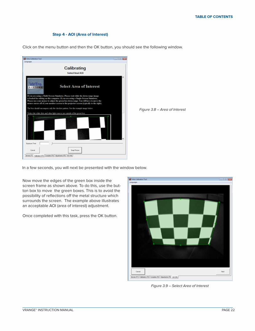
In a few seconds, you will next be presented with the window below.
Figure 3.9 – Select Area of Interest
Now move the edges of the green box inside the screen frame as shown above. To do this, use the but-ton box to move the green boxes. This is to avoid the possibility of reflections off the metal structure which surrounds the screen. The example above illustrates an acceptable AOI (area of interest) adjustment. Once completed with this task, press the OK button.
Step 4 - AOI (Area of Interest)
Click on the menu button and then the OK button, you should see the following window.
Figure 3.8 – Area of Interest
PAGE 22 PAGE 23VRANGE™ INSTRUCTION MANUAL
TABLE OF CONTENTS
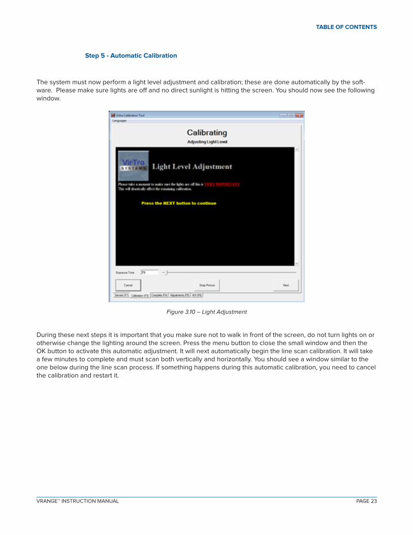
Step 5 - Automatic Calibration
The system must now perform a light level adjustment and calibration; these are done automatically by the soft-ware. Please make sure lights are off and no direct sunlight is hitting the screen. You should now see the following window.
Figure 3.10 – Light Adjustment
During these next steps it is important that you make sure not to walk in front of the screen, do not turn lights on or otherwise change the lighting around the screen. Press the menu button to close the small window and then the OK button to activate this automatic adjustment. It will next automatically begin the line scan calibration. It will take a few minutes to complete and must scan both vertically and horizontally. You should see a window similar to the one below during the line scan process. If something happens during this automatic calibration, you need to cancel the calibration and restart it.

PAGE 24VRANGE™ INSTRUCTION MANUAL
TABLE OF CONTENTS
Figure 3.11 – Line Scan
When completed you should see the following window.
Figure 3.12 – Calibration Complete
PAGE 24 PAGE 25VRANGE™ INSTRUCTION MANUAL
TABLE OF CONTENTS
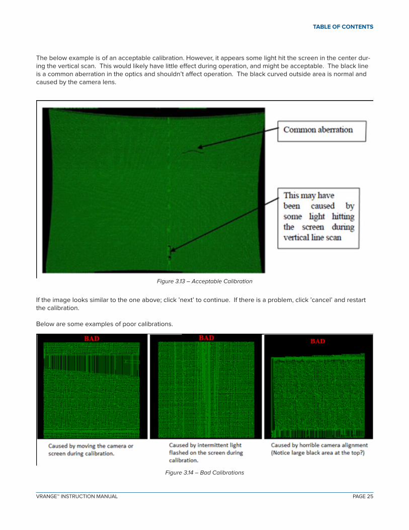
The below example is of an acceptable calibration. However, it appears some light hit the screen in the center dur-ing the vertical scan. This would likely have little effect during operation, and might be acceptable. The black line is a common aberration in the optics and shouldn’t affect operation. The black curved outside area is normal and caused by the camera lens.
Figure 3.13 – Acceptable Calibration
If the image looks similar to the one above; click ’next’ to continue. If there is a problem, click ’cancel’ and restart the calibration.
Below are some examples of poor calibrations.
Figure 3.14 – Bad Calibrations

PAGE 26VRANGE™ INSTRUCTION MANUAL
TABLE OF CONTENTS
Next, place the filter back onto the camera’s lens. The picture below shows a camera with the filter in place.
Figure 3.15 – Filter on Camera
You should now see the following window.
Figure 3.16 – Run Gain

PAGE 26 PAGE 27VRANGE™ INSTRUCTION MANUAL
TABLE OF CONTENTS
Make sure the filter is in place over the camera lens and press the menu button followed by the OK button.
Figure 3.17 – Final Run Gain
At this point the program will automatically adjust the Camera Run Gain. Once the Run Gain has been completed press the OK button.
PAGE 28VRANGE™ INSTRUCTION MANUAL
TABLE OF CONTENTS
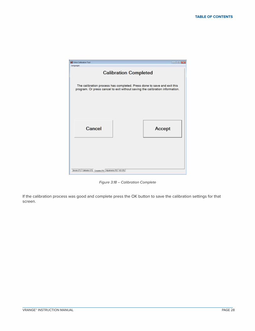
Figure 3.18 – Calibration Complete
If the calibration process was good and complete press the OK button to save the calibration settings for that screen.

PAGE 28 PAGE 29VRANGE™ INSTRUCTION MANUAL
TABLE OF CONTENTS
IV. CONTACT VIRTRA
If you have any problems/questions with the operation and set up of the VirTra Range™, please see contact below:
Brett ErnenputschService Manager
7970 S. Kyrene RoadTempe, AZ 85284 USA
Office: 480.968.1488 x 5029Mobile: 602.456.9173Email: [email protected]
To download an electronic copy of this manual, please scan the QR code below with your smartphone device or visit
www.virtra.com/PDF/Manuals/Software/VRange.pdf