virtual chassis feature guide for switches · fpcs(nssuupgradegroups) 159 id 160 lag-hash 161...
TRANSCRIPT
Virtual Chassis Feature Guide for Switches
Modified: 2018-08-15
Copyright © 2018, Juniper Networks, Inc.

Juniper Networks, Inc.1133 InnovationWaySunnyvale, California 94089USA408-745-2000www.juniper.net
Juniper Networks, the Juniper Networks logo, Juniper, and Junos are registered trademarks of Juniper Networks, Inc. and/or its affiliates inthe United States and other countries. All other trademarks may be property of their respective owners.
Juniper Networks assumes no responsibility for any inaccuracies in this document. Juniper Networks reserves the right to change, modify,transfer, or otherwise revise this publication without notice.
Virtual Chassis Feature Guide for SwitchesCopyright © 2018 Juniper Networks, Inc. All rights reserved.
The information in this document is current as of the date on the title page.
YEAR 2000 NOTICE
Juniper Networks hardware and software products are Year 2000 compliant. Junos OS has no known time-related limitations through theyear 2038. However, the NTP application is known to have some difficulty in the year 2036.
ENDUSER LICENSE AGREEMENT
The Juniper Networks product that is the subject of this technical documentation consists of (or is intended for use with) Juniper Networkssoftware. Use of such software is subject to the terms and conditions of the End User License Agreement (“EULA”) posted athttps://www.juniper.net/support/eula/. By downloading, installing or using such software, you agree to the terms and conditions of thatEULA.
Copyright © 2018, Juniper Networks, Inc.ii
Table of Contents
About the Documentation . . . . . . . . . . . . . . . . . . . . . . . . . . . . . . . . . . . . . . . . . . . . xiii
Documentation and Release Notes . . . . . . . . . . . . . . . . . . . . . . . . . . . . . . . . . xiii
Using the Examples in This Manual . . . . . . . . . . . . . . . . . . . . . . . . . . . . . . . . . xiii
Merging a Full Example . . . . . . . . . . . . . . . . . . . . . . . . . . . . . . . . . . . . . . . xiv
Merging a Snippet . . . . . . . . . . . . . . . . . . . . . . . . . . . . . . . . . . . . . . . . . . . xiv
Documentation Conventions . . . . . . . . . . . . . . . . . . . . . . . . . . . . . . . . . . . . . . xv
Documentation Feedback . . . . . . . . . . . . . . . . . . . . . . . . . . . . . . . . . . . . . . . . xvii
Requesting Technical Support . . . . . . . . . . . . . . . . . . . . . . . . . . . . . . . . . . . . xvii
Self-Help Online Tools and Resources . . . . . . . . . . . . . . . . . . . . . . . . . . xvii
Opening a Case with JTAC . . . . . . . . . . . . . . . . . . . . . . . . . . . . . . . . . . . . xviii
Chapter 1 Virtual Chassis Overview . . . . . . . . . . . . . . . . . . . . . . . . . . . . . . . . . . . . . . . . . . . 19
EX Series Virtual Chassis Overview . . . . . . . . . . . . . . . . . . . . . . . . . . . . . . . . . . . . . 19
Benefits of Virtual Chassis . . . . . . . . . . . . . . . . . . . . . . . . . . . . . . . . . . . . . . . . 20
Virtual Chassis Support on EX Series Switches . . . . . . . . . . . . . . . . . . . . . . . . 21
Basic Configuration of a Virtual Chassis . . . . . . . . . . . . . . . . . . . . . . . . . . . . . . 22
ExpandingConfigurations—Within a SingleWiring Closet andAcrossWiring
Closets . . . . . . . . . . . . . . . . . . . . . . . . . . . . . . . . . . . . . . . . . . . . . . . . . . . . 24
Global Management of Member Switches in a Virtual Chassis . . . . . . . . . . . 25
High Availability Through Redundant Routing Engines . . . . . . . . . . . . . . . . . . 25
Adaptability as an Access Switch or Distribution Switch . . . . . . . . . . . . . . . . 26
Understanding EX2300 Virtual Chassis . . . . . . . . . . . . . . . . . . . . . . . . . . . . . . . . . 26
Understanding EX3400 Virtual Chassis . . . . . . . . . . . . . . . . . . . . . . . . . . . . . . . . . 27
Understanding EX4300 Virtual Chassis . . . . . . . . . . . . . . . . . . . . . . . . . . . . . . . . . 27
Understanding EX4600 Virtual Chassis . . . . . . . . . . . . . . . . . . . . . . . . . . . . . . . . . 28
Understanding QFX Series Virtual Chassis . . . . . . . . . . . . . . . . . . . . . . . . . . . . . . . 29
QFX Virtual Chassis Overview . . . . . . . . . . . . . . . . . . . . . . . . . . . . . . . . . . . . . 30
QFX5200 Switches in a Virtual Chassis . . . . . . . . . . . . . . . . . . . . . . . . . . . . . . 31
QFX5110 Switches in a Virtual Chassis . . . . . . . . . . . . . . . . . . . . . . . . . . . . . . . 31
QFX5100 Switches in a Virtual Chassis . . . . . . . . . . . . . . . . . . . . . . . . . . . . . . 31
QFX3500 and QFX3600 Switches in a Virtual Chassis . . . . . . . . . . . . . . . . . 33
EX4300 Switches in a QFX Series Virtual Chassis . . . . . . . . . . . . . . . . . . . . . 33
Understanding Virtual Chassis Components . . . . . . . . . . . . . . . . . . . . . . . . . . . . . 34
Maximum Switch Support . . . . . . . . . . . . . . . . . . . . . . . . . . . . . . . . . . . . . . . . 35
Maximum Number of Switches in an EX Series Virtual Chassis . . . . . . . 35
Maximum Switch Support in a QFX Series Virtual Chassis (Including
Mixed Virtual Chassis with EX Series Switches) . . . . . . . . . . . . . . . . 37
Virtual Chassis Ports (VCPs) . . . . . . . . . . . . . . . . . . . . . . . . . . . . . . . . . . . . . . 38
Virtual Chassis Port Options . . . . . . . . . . . . . . . . . . . . . . . . . . . . . . . . . . . 38
Automatic Virtual Chassis Port (VCP) Conversion . . . . . . . . . . . . . . . . . . 39
Virtual Chassis Port Link Aggregation Groups . . . . . . . . . . . . . . . . . . . . . . 41
iiiCopyright © 2018, Juniper Networks, Inc.

Master Routing Engine Role . . . . . . . . . . . . . . . . . . . . . . . . . . . . . . . . . . . . . . . 41
Backup Routing Engine Role . . . . . . . . . . . . . . . . . . . . . . . . . . . . . . . . . . . . . . . 42
Linecard Role . . . . . . . . . . . . . . . . . . . . . . . . . . . . . . . . . . . . . . . . . . . . . . . . . . . 43
Member Switch and Member ID . . . . . . . . . . . . . . . . . . . . . . . . . . . . . . . . . . . . 43
Mastership Priority . . . . . . . . . . . . . . . . . . . . . . . . . . . . . . . . . . . . . . . . . . . . . . 44
Virtual Chassis Identifier (VCID) . . . . . . . . . . . . . . . . . . . . . . . . . . . . . . . . . . . . 45
UnderstandingMixedEXSeriesandQFXSeriesVirtualChassisorVirtualChassis
Fabric . . . . . . . . . . . . . . . . . . . . . . . . . . . . . . . . . . . . . . . . . . . . . . . . . . . . . . . . 46
Virtual Chassis Fabric Summary . . . . . . . . . . . . . . . . . . . . . . . . . . . . . . . . . . . . 47
Understanding Mixed and Non-Mixed Virtual Chassis Fabric . . . . . . . . . . . . . 48
Virtual Chassis Summary for QFX5200, QFX5110, QFX5100, QFX3600,
QFX3500, EX4600, and EX4300 Switches . . . . . . . . . . . . . . . . . . . . . . . 49
Understanding the Routing Engine Role in a Virtual Chassis With Different
Types of Switches . . . . . . . . . . . . . . . . . . . . . . . . . . . . . . . . . . . . . . . . . . . 50
Understanding QFX5100 and QFX5110 Switches in a Virtual Chassis . . . . . . . 51
Understanding EX4300, QFX3500, QFX3600, and QFX5100 Switches in a
Mixed Virtual Chassis . . . . . . . . . . . . . . . . . . . . . . . . . . . . . . . . . . . . . . . . . 51
Understanding Mixed EX4300 and EX4600 Virtual Chassis . . . . . . . . . . . . . 52
Understanding EX4300Multigigabit and Other EX4300Model Switches in
a Mixed EX4300 Virtual Chassis . . . . . . . . . . . . . . . . . . . . . . . . . . . . . . . . 52
Understanding EX4200, EX4500, and EX4550 Switches in a Mixed Virtual
Chassis . . . . . . . . . . . . . . . . . . . . . . . . . . . . . . . . . . . . . . . . . . . . . . . . . . . . 52
Understanding How the Master in a Virtual Chassis Is Elected . . . . . . . . . . . . . . . 53
Understanding Global Management of a Virtual Chassis . . . . . . . . . . . . . . . . . . . 54
Understanding Nonvolatile Storage in a Virtual Chassis . . . . . . . . . . . . . . . . . . . . . 57
Nonvolatile Memory Features . . . . . . . . . . . . . . . . . . . . . . . . . . . . . . . . . . . . . . 57
Understanding Virtual Chassis Port Link Aggregation . . . . . . . . . . . . . . . . . . . . . . 57
Virtual Chassis Network Interface LAG Among Virtual Chassis Members . . . 58
Virtual Chassis Port LAG Between Two Virtual Chassis Members . . . . . . . . . 58
Understanding EX Series Virtual Chassis Configuration . . . . . . . . . . . . . . . . . . . . . 59
Standalone Switch Virtual Chassis Characteristics . . . . . . . . . . . . . . . . . . . . 59
Interconnecting Virtual Chassis Members with Virtual Chassis Ports . . . . . . 60
Virtual Chassis Provisioning . . . . . . . . . . . . . . . . . . . . . . . . . . . . . . . . . . . . . . . 60
Understanding Split and Merge in a Virtual Chassis . . . . . . . . . . . . . . . . . . . . . . . . 61
What Happens When a Virtual Chassis Configuration Splits . . . . . . . . . . . . . 62
Merging Virtual Chassis Configurations . . . . . . . . . . . . . . . . . . . . . . . . . . . . . . 63
Understanding Automatic Software Update on Virtual Chassis Member
Switches . . . . . . . . . . . . . . . . . . . . . . . . . . . . . . . . . . . . . . . . . . . . . . . . . . . . . . 64
Automatic Software Update Basics . . . . . . . . . . . . . . . . . . . . . . . . . . . . . . . . 64
Automatic Software Update Restrictions . . . . . . . . . . . . . . . . . . . . . . . . . . . . 65
Understanding MAC Address Assignment on a Virtual Chassis . . . . . . . . . . . . . . . 65
Understanding High Availability on an EX Series Virtual Chassis . . . . . . . . . . . . . . 67
Copyright © 2018, Juniper Networks, Inc.iv
Virtual Chassis Feature Guide for Switches

Chapter 2 Virtual Chassis Configuration . . . . . . . . . . . . . . . . . . . . . . . . . . . . . . . . . . . . . . . 69
Configuring an EX2300, EX3400, or EX4300 Virtual Chassis . . . . . . . . . . . . . . . . 69
Configuring an EX2300, EX3400, or EX4300 Virtual Chassis with a
Nonprovisioned Configuration File . . . . . . . . . . . . . . . . . . . . . . . . . . . . . . 72
Configuring an EX2300, EX3400, or EX4300 Virtual Chassis with a
Preprovisioned Configuration File . . . . . . . . . . . . . . . . . . . . . . . . . . . . . . . 75
Configuring EX4600 Switches in a Mixed or Non-Mixed Virtual Chassis (CLI
Procedure) . . . . . . . . . . . . . . . . . . . . . . . . . . . . . . . . . . . . . . . . . . . . . . . . . . . . . 79
ConfiguringanEX4600VirtualChassiswithaNonprovisionedConfiguration
File . . . . . . . . . . . . . . . . . . . . . . . . . . . . . . . . . . . . . . . . . . . . . . . . . . . . . . . 80
Configuring anEX4600Virtual Chassiswith aPreprovisionedConfiguration
File . . . . . . . . . . . . . . . . . . . . . . . . . . . . . . . . . . . . . . . . . . . . . . . . . . . . . . . 82
Configuring a QFX Series Virtual Chassis (CLI Procedure) . . . . . . . . . . . . . . . . . . . 84
Understanding the Licensing Requirements for a QFX Series Virtual
Chassis . . . . . . . . . . . . . . . . . . . . . . . . . . . . . . . . . . . . . . . . . . . . . . . . . . . . 86
ConfiguringaQFXSeriesVirtualChassiswithaPreprovisionedConfiguration
File . . . . . . . . . . . . . . . . . . . . . . . . . . . . . . . . . . . . . . . . . . . . . . . . . . . . . . . 86
ConfiguringaQFXSeriesVirtualChassiswithaNonprovisionedConfiguration
File . . . . . . . . . . . . . . . . . . . . . . . . . . . . . . . . . . . . . . . . . . . . . . . . . . . . . . . 89
Adding a New Switch to an Existing EX2300, EX3400, or EX4300 Virtual
Chassis . . . . . . . . . . . . . . . . . . . . . . . . . . . . . . . . . . . . . . . . . . . . . . . . . . . . . . . 92
Adding an EX4600 Switch to a Mixed or Non-mixed Virtual Chassis (CLI
Procedure) . . . . . . . . . . . . . . . . . . . . . . . . . . . . . . . . . . . . . . . . . . . . . . . . . . . . 96
Adding a New Switch to an Existing QFX Series Virtual Chassis (CLI
Procedure) . . . . . . . . . . . . . . . . . . . . . . . . . . . . . . . . . . . . . . . . . . . . . . . . . . . . 98
Replacing a Member Switch of a Virtual Chassis Configuration (CLI
Procedure) . . . . . . . . . . . . . . . . . . . . . . . . . . . . . . . . . . . . . . . . . . . . . . . . . . . . 101
Remove, Repair, and Reinstall the Same Switch . . . . . . . . . . . . . . . . . . . . . . 101
Remove a Member Switch, Replace It with a Different Switch, and Reapply
the Old Configuration . . . . . . . . . . . . . . . . . . . . . . . . . . . . . . . . . . . . . . . . 102
Remove a Member Switch and Make Its Member ID Available for
Reassignment to a Different Switch . . . . . . . . . . . . . . . . . . . . . . . . . . . . 105
Configuring Mastership of a Virtual Chassis (CLI Procedure) . . . . . . . . . . . . . . . . 105
Configuring Mastership Using a Preprovisioned Configuration File . . . . . . . . 106
Configuring Mastership Using a Configuration File That Is Not
Preprovisioned . . . . . . . . . . . . . . . . . . . . . . . . . . . . . . . . . . . . . . . . . . . . . 107
Configuring the Timer for the Backup Member to Start Using Its OwnMAC
Address, as Master of a Virtual Chassis (CLI Procedure) . . . . . . . . . . . . . . . . 108
Setting an Uplink Port on an EX Series or QFX Series Switch as a Virtual Chassis
Port . . . . . . . . . . . . . . . . . . . . . . . . . . . . . . . . . . . . . . . . . . . . . . . . . . . . . . . . . 108
Setting an Uplink VCP Between the Member Switches in a Virtual
Chassis . . . . . . . . . . . . . . . . . . . . . . . . . . . . . . . . . . . . . . . . . . . . . . . . . . . . 111
Setting an Uplink VCP on a Standalone Switch . . . . . . . . . . . . . . . . . . . . . . . 112
Disabling Split and Merge in a Virtual Chassis (CLI Procedure) . . . . . . . . . . . . . . . 114
Configuring Automatic Software Update on Virtual Chassis Member Switches
(CLI Procedure) . . . . . . . . . . . . . . . . . . . . . . . . . . . . . . . . . . . . . . . . . . . . . . . . 114
Assigning theVirtualChassis ID toDeterminePrecedenceDuringaVirtualChassis
Merge (CLI Procedure) . . . . . . . . . . . . . . . . . . . . . . . . . . . . . . . . . . . . . . . . . . . 117
vCopyright © 2018, Juniper Networks, Inc.
Table of Contents

Configuring Graceful Routing Engine Switchover in a Virtual Chassis (CLI
Procedure) . . . . . . . . . . . . . . . . . . . . . . . . . . . . . . . . . . . . . . . . . . . . . . . . . . . . 117
Chapter 3 Virtual Chassis Routine Monitoring and Troubleshooting . . . . . . . . . . . . . . 119
Command Forwarding Usage with an EX Series Virtual Chassis . . . . . . . . . . . . . 119
Verifying the Member ID, Role, and Neighbor Member Connections of a Virtual
Chassis Member . . . . . . . . . . . . . . . . . . . . . . . . . . . . . . . . . . . . . . . . . . . . . . . 124
Verifying That Virtual Chassis Ports Are Operational . . . . . . . . . . . . . . . . . . . . . . 125
Verifying That Graceful Routing Engine Switchover Is Working in the Virtual
Chassis . . . . . . . . . . . . . . . . . . . . . . . . . . . . . . . . . . . . . . . . . . . . . . . . . . . . . . . 127
Troubleshooting an EX Series Virtual Chassis . . . . . . . . . . . . . . . . . . . . . . . . . . . . 128
A Disconnected Member Switch's ID Is Not Available for Reassignment . . . 129
Load Factory Default Does Not Commit on a Multimember Virtual
Chassis . . . . . . . . . . . . . . . . . . . . . . . . . . . . . . . . . . . . . . . . . . . . . . . . . . . 129
The Member ID Persists When a Member Switch Is Disconnected From a
Virtual Chassis . . . . . . . . . . . . . . . . . . . . . . . . . . . . . . . . . . . . . . . . . . . . . 129
A Member Switch Is Not Participating in a Mixed Virtual Chassis . . . . . . . . . 130
Unknown Traffic Looping Occurs After Configuring an Uplink Port as a
Redundant VCP with a Dedicated VCP . . . . . . . . . . . . . . . . . . . . . . . . . . 131
Chapter 4 Upgrading Software on a Virtual Chassis . . . . . . . . . . . . . . . . . . . . . . . . . . . . 133
Understanding Software Upgrades in a Virtual Chassis . . . . . . . . . . . . . . . . . . . . 133
Automatic Software Updates . . . . . . . . . . . . . . . . . . . . . . . . . . . . . . . . . . . . . 134
Nonstop Software Upgrade . . . . . . . . . . . . . . . . . . . . . . . . . . . . . . . . . . . . . . 134
UpgradingaQFX5100SwitchwithaUSBDevice to JoinaQFX5110VirtualChassis
or Virtual Chassis Fabric . . . . . . . . . . . . . . . . . . . . . . . . . . . . . . . . . . . . . . . . . 135
IdentifyingCompatibleSoftware forQFX5100Switches toRun inaQFX5110
Virtual Chassis or VCF . . . . . . . . . . . . . . . . . . . . . . . . . . . . . . . . . . . . . . . 135
Creating a USB Boot Device for a QFX5100 Switch . . . . . . . . . . . . . . . . . . . . 137
Upgrading a QFX5100 Switch from Junos OS “QFX 5 Series” to “QFX 5e
Series” Software Using a USB Boot Device . . . . . . . . . . . . . . . . . . . . . . . 139
UnderstandingNonstopSoftwareUpgradeonaVirtualChassisandMixedVirtual
Chassis . . . . . . . . . . . . . . . . . . . . . . . . . . . . . . . . . . . . . . . . . . . . . . . . . . . . . . . 140
Benefits of NSSU . . . . . . . . . . . . . . . . . . . . . . . . . . . . . . . . . . . . . . . . . . . . . . 140
Requirements for Performing an NSSU . . . . . . . . . . . . . . . . . . . . . . . . . . . . . . 141
How an NSSUWorks on a Virtual Chassis and Mixed Virtual Chassis . . . . . . 142
NSSU Limitations . . . . . . . . . . . . . . . . . . . . . . . . . . . . . . . . . . . . . . . . . . . . . . 143
NSSU and Junos OS Release Support . . . . . . . . . . . . . . . . . . . . . . . . . . . . . . 144
Overview of NSSU Configuration and Operation . . . . . . . . . . . . . . . . . . . . . . 144
Configuring Line-Card Upgrade Groups for Nonstop Software Upgrade (CLI
Procedure) . . . . . . . . . . . . . . . . . . . . . . . . . . . . . . . . . . . . . . . . . . . . . . . . . . . . 145
UpgradingSoftwareonaVirtualChassisandMixedVirtualChassisUsingNonstop
Software Upgrade . . . . . . . . . . . . . . . . . . . . . . . . . . . . . . . . . . . . . . . . . . . . . . 147
Preparing the Switch for Software Installation . . . . . . . . . . . . . . . . . . . . . . . 148
Upgrading the Software Using NSSU . . . . . . . . . . . . . . . . . . . . . . . . . . . . . . . 150
Chapter 5 Configuration Statements . . . . . . . . . . . . . . . . . . . . . . . . . . . . . . . . . . . . . . . . . 153
aliases (Virtual Chassis) . . . . . . . . . . . . . . . . . . . . . . . . . . . . . . . . . . . . . . . . . . . . . 154
alias-name (Virtual Chassis aliases) . . . . . . . . . . . . . . . . . . . . . . . . . . . . . . . . . . . 155
auto-sw-update . . . . . . . . . . . . . . . . . . . . . . . . . . . . . . . . . . . . . . . . . . . . . . . . . . . 156
Copyright © 2018, Juniper Networks, Inc.vi
Virtual Chassis Feature Guide for Switches

fpcs (NSSU Upgrade Groups) . . . . . . . . . . . . . . . . . . . . . . . . . . . . . . . . . . . . . . . . 159
id . . . . . . . . . . . . . . . . . . . . . . . . . . . . . . . . . . . . . . . . . . . . . . . . . . . . . . . . . . . . . . . 160
lag-hash . . . . . . . . . . . . . . . . . . . . . . . . . . . . . . . . . . . . . . . . . . . . . . . . . . . . . . . . . . 161
location (Virtual Chassis) . . . . . . . . . . . . . . . . . . . . . . . . . . . . . . . . . . . . . . . . . . . . 162
mac-persistence-timer . . . . . . . . . . . . . . . . . . . . . . . . . . . . . . . . . . . . . . . . . . . . . . 163
mastership-priority . . . . . . . . . . . . . . . . . . . . . . . . . . . . . . . . . . . . . . . . . . . . . . . . . 164
member . . . . . . . . . . . . . . . . . . . . . . . . . . . . . . . . . . . . . . . . . . . . . . . . . . . . . . . . . . 165
member (NSSU Upgrade Groups) . . . . . . . . . . . . . . . . . . . . . . . . . . . . . . . . . . . . . 167
no-auto-conversion . . . . . . . . . . . . . . . . . . . . . . . . . . . . . . . . . . . . . . . . . . . . . . . . 168
no-management-vlan . . . . . . . . . . . . . . . . . . . . . . . . . . . . . . . . . . . . . . . . . . . . . . 169
no-split-detection . . . . . . . . . . . . . . . . . . . . . . . . . . . . . . . . . . . . . . . . . . . . . . . . . . 170
nssu . . . . . . . . . . . . . . . . . . . . . . . . . . . . . . . . . . . . . . . . . . . . . . . . . . . . . . . . . . . . . 171
package-name . . . . . . . . . . . . . . . . . . . . . . . . . . . . . . . . . . . . . . . . . . . . . . . . . . . . 172
preprovisioned . . . . . . . . . . . . . . . . . . . . . . . . . . . . . . . . . . . . . . . . . . . . . . . . . . . . . 173
rcp-count . . . . . . . . . . . . . . . . . . . . . . . . . . . . . . . . . . . . . . . . . . . . . . . . . . . . . . . . . 174
role . . . . . . . . . . . . . . . . . . . . . . . . . . . . . . . . . . . . . . . . . . . . . . . . . . . . . . . . . . . . . . 176
serial-number . . . . . . . . . . . . . . . . . . . . . . . . . . . . . . . . . . . . . . . . . . . . . . . . . . . . . 179
serial-number (Virtual Chassis aliases) . . . . . . . . . . . . . . . . . . . . . . . . . . . . . . . . 180
traceoptions (Virtual Chassis) . . . . . . . . . . . . . . . . . . . . . . . . . . . . . . . . . . . . . . . . 181
upgrade-group . . . . . . . . . . . . . . . . . . . . . . . . . . . . . . . . . . . . . . . . . . . . . . . . . . . . 184
vc-port . . . . . . . . . . . . . . . . . . . . . . . . . . . . . . . . . . . . . . . . . . . . . . . . . . . . . . . . . . . 185
vcp-no-hold-time . . . . . . . . . . . . . . . . . . . . . . . . . . . . . . . . . . . . . . . . . . . . . . . . . . 186
vcp-snmp-statistics . . . . . . . . . . . . . . . . . . . . . . . . . . . . . . . . . . . . . . . . . . . . . . . . 187
virtual-chassis . . . . . . . . . . . . . . . . . . . . . . . . . . . . . . . . . . . . . . . . . . . . . . . . . . . . 188
Chapter 6 Operational Commands . . . . . . . . . . . . . . . . . . . . . . . . . . . . . . . . . . . . . . . . . . . 191
clear virtual-chassis vc-port statistics . . . . . . . . . . . . . . . . . . . . . . . . . . . . . . . . . . 192
request session member . . . . . . . . . . . . . . . . . . . . . . . . . . . . . . . . . . . . . . . . . . . . 194
request system software nonstop-upgrade . . . . . . . . . . . . . . . . . . . . . . . . . . . . . 195
request virtual-chassis mode . . . . . . . . . . . . . . . . . . . . . . . . . . . . . . . . . . . . . . . . 205
request virtual-chassis recycle . . . . . . . . . . . . . . . . . . . . . . . . . . . . . . . . . . . . . . . 209
request virtual-chassis renumber . . . . . . . . . . . . . . . . . . . . . . . . . . . . . . . . . . . . . 210
request virtual-chassis vc-port . . . . . . . . . . . . . . . . . . . . . . . . . . . . . . . . . . . . . . . . 211
request virtual-chassis vc-port diagnostics optics . . . . . . . . . . . . . . . . . . . . . . . . 213
show chassis nonstop-upgrade . . . . . . . . . . . . . . . . . . . . . . . . . . . . . . . . . . . . . . . 214
show virtual-chassis . . . . . . . . . . . . . . . . . . . . . . . . . . . . . . . . . . . . . . . . . . . . . . . . 216
show virtual-chassis active-topology . . . . . . . . . . . . . . . . . . . . . . . . . . . . . . . . . . 222
show virtual-chassis device-topology . . . . . . . . . . . . . . . . . . . . . . . . . . . . . . . . . . 227
show virtual-chassis login . . . . . . . . . . . . . . . . . . . . . . . . . . . . . . . . . . . . . . . . . . . 233
show virtual-chassis mode . . . . . . . . . . . . . . . . . . . . . . . . . . . . . . . . . . . . . . . . . . 234
show virtual-chassis protocol adjacency . . . . . . . . . . . . . . . . . . . . . . . . . . . . . . . 237
show virtual-chassis protocol database . . . . . . . . . . . . . . . . . . . . . . . . . . . . . . . . 241
show virtual-chassis protocol interface . . . . . . . . . . . . . . . . . . . . . . . . . . . . . . . . 245
show virtual-chassis protocol route . . . . . . . . . . . . . . . . . . . . . . . . . . . . . . . . . . . 248
show virtual-chassis protocol statistics . . . . . . . . . . . . . . . . . . . . . . . . . . . . . . . . . 251
show virtual-chassis vc-path . . . . . . . . . . . . . . . . . . . . . . . . . . . . . . . . . . . . . . . . 254
show virtual-chassis vc-port . . . . . . . . . . . . . . . . . . . . . . . . . . . . . . . . . . . . . . . . . 258
show virtual-chassis vc-port diagnostics optics . . . . . . . . . . . . . . . . . . . . . . . . . . 262
show virtual-chassis vc-port statistics . . . . . . . . . . . . . . . . . . . . . . . . . . . . . . . . . 276
viiCopyright © 2018, Juniper Networks, Inc.
Table of Contents

Copyright © 2018, Juniper Networks, Inc.viii
Virtual Chassis Feature Guide for Switches

List of Figures
Chapter 1 Virtual Chassis Overview . . . . . . . . . . . . . . . . . . . . . . . . . . . . . . . . . . . . . . . . . . . 19
Figure 1: Console Session Redirection (EX4200 Virtual Chassis Pictured) . . . . . . 55
Figure 2: Management Ethernet Port Redirection to the VME Interface . . . . . . . . 56
ixCopyright © 2018, Juniper Networks, Inc.

Copyright © 2018, Juniper Networks, Inc.x
Virtual Chassis Feature Guide for Switches

List of Tables
About the Documentation . . . . . . . . . . . . . . . . . . . . . . . . . . . . . . . . . . . . . . . . . xiii
Table 1: Notice Icons . . . . . . . . . . . . . . . . . . . . . . . . . . . . . . . . . . . . . . . . . . . . . . . . . xv
Table 2: Text and Syntax Conventions . . . . . . . . . . . . . . . . . . . . . . . . . . . . . . . . . . . xv
Chapter 1 Virtual Chassis Overview . . . . . . . . . . . . . . . . . . . . . . . . . . . . . . . . . . . . . . . . . . . 19
Table 3: Minimum Junos OS Release by Virtual Chassis Connection Type . . . . . . 22
Table 4: MaximumMember Switch Support for Virtual Chassis by Junos OS
Release . . . . . . . . . . . . . . . . . . . . . . . . . . . . . . . . . . . . . . . . . . . . . . . . . . . . . . . 35
Table 5: VCP Options by Switch Type . . . . . . . . . . . . . . . . . . . . . . . . . . . . . . . . . . . 38
Table 6: Virtual Chassis Fabric Summary . . . . . . . . . . . . . . . . . . . . . . . . . . . . . . . . 48
Table 7: Virtual Chassis Summary . . . . . . . . . . . . . . . . . . . . . . . . . . . . . . . . . . . . . . 49
Table 8: Effects of a Routing Engine Switchover . . . . . . . . . . . . . . . . . . . . . . . . . . . 67
Chapter 3 Virtual Chassis Routine Monitoring and Troubleshooting . . . . . . . . . . . . . . 119
Table 9: Commands That Can be Run on All or Specific Members of the Virtual
Chassis Configuration . . . . . . . . . . . . . . . . . . . . . . . . . . . . . . . . . . . . . . . . . . . 120
Chapter 6 Operational Commands . . . . . . . . . . . . . . . . . . . . . . . . . . . . . . . . . . . . . . . . . . . 191
Table 10: show chassis nonstop-upgrade Output Fields . . . . . . . . . . . . . . . . . . . 214
Table 11: show virtual-chassis Output Fields . . . . . . . . . . . . . . . . . . . . . . . . . . . . . 216
Table 12: show virtual-chassis active-topology Output Fields . . . . . . . . . . . . . . . 222
Table 13: show virtual-chassis device-topology Output Fields . . . . . . . . . . . . . . . 227
Table 14: show virtual-chassis mode Output Fields . . . . . . . . . . . . . . . . . . . . . . . 234
Table 15: show virtual-chassis protocol adjacency Output Fields . . . . . . . . . . . . 238
Table 16: show virtual-chassis protocol database Output Fields . . . . . . . . . . . . . 242
Table 17: show virtual-chassis protocol interface Output Fields . . . . . . . . . . . . . 246
Table 18: show virtual-chassis protocol route Output Fields . . . . . . . . . . . . . . . . 248
Table 19: show virtual-chassis protocol statistics Output Fields . . . . . . . . . . . . . 251
Table 20: show virtual-chassis vc-path Output Fields . . . . . . . . . . . . . . . . . . . . . 255
Table 21: show virtual-chassis vc-port Output Fields . . . . . . . . . . . . . . . . . . . . . . 258
Table 22: show virtual-chassis vc-port diagnostics optics Output Fields . . . . . . 263
Table 23: show virtual-chassis vc-port statistics Output Fields . . . . . . . . . . . . . . 277
xiCopyright © 2018, Juniper Networks, Inc.

Copyright © 2018, Juniper Networks, Inc.xii
Virtual Chassis Feature Guide for Switches

About the Documentation
• Documentation and Release Notes on page xiii
• Using the Examples in This Manual on page xiii
• Documentation Conventions on page xv
• Documentation Feedback on page xvii
• Requesting Technical Support on page xvii
Documentation and Release Notes
To obtain the most current version of all Juniper Networks®technical documentation,
see the product documentation page on the Juniper Networks website at
https://www.juniper.net/documentation/.
If the information in the latest release notes differs from the information in the
documentation, follow the product Release Notes.
Juniper Networks Books publishes books by Juniper Networks engineers and subject
matter experts. These books go beyond the technical documentation to explore the
nuances of network architecture, deployment, and administration. The current list can
be viewed at https://www.juniper.net/books.
Using the Examples in This Manual
If you want to use the examples in this manual, you can use the loadmerge or the load
merge relative command. These commands cause the software to merge the incoming
configuration into the current candidate configuration. The example does not become
active until you commit the candidate configuration.
If the example configuration contains the top level of the hierarchy (or multiple
hierarchies), the example is a full example. In this case, use the loadmerge command.
If the example configuration does not start at the top level of the hierarchy, the example
is a snippet. In this case, use the loadmerge relative command. These procedures are
described in the following sections.
xiiiCopyright © 2018, Juniper Networks, Inc.

Merging a Full Example
Tomerge a full example, follow these steps:
1. From the HTML or PDF version of the manual, copy a configuration example into a
text file, save the file with a name, and copy the file to a directory on your routing
platform.
For example, copy the following configuration toa file andname the file ex-script.conf.
Copy the ex-script.conf file to the /var/tmp directory on your routing platform.
system {scripts {commit {file ex-script.xsl;
}}
}interfaces {fxp0 {disable;unit 0 {family inet {address 10.0.0.1/24;
}}
}}
2. Merge the contents of the file into your routing platform configuration by issuing the
loadmerge configuration mode command:
[edit]user@host# loadmerge /var/tmp/ex-script.confload complete
Merging a Snippet
Tomerge a snippet, follow these steps:
1. From the HTML or PDF version of themanual, copy a configuration snippet into a text
file, save the file with a name, and copy the file to a directory on your routing platform.
For example, copy the following snippet to a file and name the file
ex-script-snippet.conf. Copy the ex-script-snippet.conf file to the /var/tmp directory
on your routing platform.
commit {file ex-script-snippet.xsl; }
2. Move to the hierarchy level that is relevant for this snippet by issuing the following
configuration mode command:
[edit]
Copyright © 2018, Juniper Networks, Inc.xiv
Virtual Chassis Feature Guide for Switches

user@host# edit system scripts[edit system scripts]
3. Merge the contents of the file into your routing platform configuration by issuing the
loadmerge relative configuration mode command:
[edit system scripts]user@host# loadmerge relative /var/tmp/ex-script-snippet.confload complete
For more information about the load command, see CLI Explorer.
Documentation Conventions
Table 1 on page xv defines notice icons used in this guide.
Table 1: Notice Icons
DescriptionMeaningIcon
Indicates important features or instructions.Informational note
Indicates a situation that might result in loss of data or hardware damage.Caution
Alerts you to the risk of personal injury or death.Warning
Alerts you to the risk of personal injury from a laser.Laser warning
Indicates helpful information.Tip
Alerts you to a recommended use or implementation.Best practice
Table 2 on page xv defines the text and syntax conventions used in this guide.
Table 2: Text and Syntax Conventions
ExamplesDescriptionConvention
To enter configuration mode, type theconfigure command:
user@host> configure
Represents text that you type.Bold text like this
xvCopyright © 2018, Juniper Networks, Inc.
About the Documentation

Table 2: Text and Syntax Conventions (continued)
ExamplesDescriptionConvention
user@host> show chassis alarms
No alarms currently active
Represents output that appears on theterminal screen.
Fixed-width text like this
• A policy term is a named structurethat defines match conditions andactions.
• Junos OS CLI User Guide
• RFC 1997,BGPCommunities Attribute
• Introduces or emphasizes importantnew terms.
• Identifies guide names.
• Identifies RFC and Internet draft titles.
Italic text like this
Configure themachine’s domain name:
[edit]root@# set system domain-namedomain-name
Represents variables (options for whichyou substitute a value) in commands orconfiguration statements.
Italic text like this
• To configure a stub area, include thestub statement at the [edit protocolsospf area area-id] hierarchy level.
• Theconsoleport is labeledCONSOLE.
Represents names of configurationstatements, commands, files, anddirectories; configurationhierarchy levels;or labels on routing platformcomponents.
Text like this
stub <default-metricmetric>;Encloses optional keywords or variables.< > (angle brackets)
broadcast | multicast
(string1 | string2 | string3)
Indicates a choice between themutuallyexclusive keywords or variables on eitherside of the symbol. The set of choices isoften enclosed in parentheses for clarity.
| (pipe symbol)
rsvp { # Required for dynamicMPLS onlyIndicates a comment specified on thesame lineas theconfiguration statementto which it applies.
# (pound sign)
community namemembers [community-ids ]
Encloses a variable for which you cansubstitute one or more values.
[ ] (square brackets)
[edit]routing-options {static {route default {nexthop address;retain;
}}
}
Identifies a level in the configurationhierarchy.
Indention and braces ( { } )
Identifies a leaf statement at aconfiguration hierarchy level.
; (semicolon)
GUI Conventions
• In the Logical Interfaces box, selectAll Interfaces.
• To cancel the configuration, clickCancel.
Representsgraphicaluser interface(GUI)items you click or select.
Bold text like this
Copyright © 2018, Juniper Networks, Inc.xvi
Virtual Chassis Feature Guide for Switches
Table 2: Text and Syntax Conventions (continued)
ExamplesDescriptionConvention
In the configuration editor hierarchy,select Protocols>Ospf.
Separates levels in a hierarchy of menuselections.
> (bold right angle bracket)
Documentation Feedback
We encourage you to provide feedback, comments, and suggestions so that we can
improve the documentation. You can provide feedback by using either of the following
methods:
• Online feedback rating system—On any page of the Juniper Networks TechLibrary site
at https://www.juniper.net/documentation/index.html, simply click the stars to rate the
content, anduse thepop-up formtoprovideuswith informationabout your experience.
Alternately, you can use the online feedback form at
https://www.juniper.net/documentation/feedback/.
• E-mail—Sendyourcommentsto [email protected]. Includethedocument
or topic name, URL or page number, and software version (if applicable).
Requesting Technical Support
Technical product support is available through the JuniperNetworksTechnicalAssistance
Center (JTAC). If you are a customer with an active J-Care or Partner Support Service
support contract, or are covered under warranty, and need post-sales technical support,
you can access our tools and resources online or open a case with JTAC.
• JTAC policies—For a complete understanding of our JTAC procedures and policies,
review the JTAC User Guide located at
https://www.juniper.net/us/en/local/pdf/resource-guides/7100059-en.pdf.
• Product warranties—For product warranty information, visit
https://www.juniper.net/support/warranty/.
• JTAC hours of operation—The JTAC centers have resources available 24 hours a day,
7 days a week, 365 days a year.
Self-Help Online Tools and Resources
For quick and easy problem resolution, Juniper Networks has designed an online
self-service portal called the Customer Support Center (CSC) that provides youwith the
following features:
• Find CSC offerings: https://www.juniper.net/customers/support/
• Search for known bugs: https://prsearch.juniper.net/
• Find product documentation: https://www.juniper.net/documentation/
• Find solutions and answer questions using our Knowledge Base: https://kb.juniper.net/
xviiCopyright © 2018, Juniper Networks, Inc.
About the Documentation

• Download the latest versions of software and review release notes:
https://www.juniper.net/customers/csc/software/
• Search technical bulletins for relevant hardware and software notifications:
https://kb.juniper.net/InfoCenter/
• Join and participate in the Juniper Networks Community Forum:
https://www.juniper.net/company/communities/
• Open a case online in the CSC Case Management tool: https://www.juniper.net/cm/
Toverify serviceentitlementbyproduct serial number, useourSerialNumberEntitlement
(SNE) Tool: https://entitlementsearch.juniper.net/entitlementsearch/
Opening a Casewith JTAC
You can open a case with JTAC on theWeb or by telephone.
• Use the Case Management tool in the CSC at https://www.juniper.net/cm/.
• Call 1-888-314-JTAC (1-888-314-5822 toll-free in the USA, Canada, and Mexico).
For international or direct-dial options in countries without toll-free numbers, see
https://www.juniper.net/support/requesting-support.html.
Copyright © 2018, Juniper Networks, Inc.xviii
Virtual Chassis Feature Guide for Switches

CHAPTER 1
Virtual Chassis Overview
• EX Series Virtual Chassis Overview on page 19
• Understanding EX2300 Virtual Chassis on page 26
• Understanding EX3400 Virtual Chassis on page 27
• Understanding EX4300 Virtual Chassis on page 27
• Understanding EX4600 Virtual Chassis on page 28
• Understanding QFX Series Virtual Chassis on page 29
• Understanding Virtual Chassis Components on page 34
• Understanding Mixed EX Series and QFX Series Virtual Chassis or Virtual Chassis
Fabric on page 46
• Understanding How the Master in a Virtual Chassis Is Elected on page 53
• Understanding Global Management of a Virtual Chassis on page 54
• Understanding Nonvolatile Storage in a Virtual Chassis on page 57
• Understanding Virtual Chassis Port Link Aggregation on page 57
• Understanding EX Series Virtual Chassis Configuration on page 59
• Understanding Split and Merge in a Virtual Chassis on page 61
• Understanding Automatic Software Update on Virtual Chassis Member
Switches on page 64
• Understanding MAC Address Assignment on a Virtual Chassis on page 65
• Understanding High Availability on an EX Series Virtual Chassis on page 67
EX Series Virtual Chassis Overview
Many Juniper Networks EX Series switches support the Virtual Chassis flexible, scaling
switch solution. You can connect individual switches together to form one unit and
manage the unit as a single chassis. Virtual Chassis ports (VCPs) connect switches
(Virtual Chassis members) together to form a Virtual Chassis, and are responsible for
passing all data and control traffic betweenmembers.
19Copyright © 2018, Juniper Networks, Inc.

The following feature guides describe Virtual Chassis on different switches:
• Virtual Chassis Feature Guide for EX2200, EX3300, EX4200, EX4500 and EX4550
Switches covers configuring andmaintaining EX2200, EX3300, EX4200, EX4500, and
EX4550 Virtual Chassis.
• VirtualChassisFeatureGuide forEX8200Switchesdescribesconfiguringandmaintaining
EX8200 Virtual Chassis.
• FordeploymentswithEX9200switches,we recommendplanningormoving toMC-LAG
or Junos Fusion Enterprise architectures rather than using a Virtual Chassis. We do not
recommend using EX9200 switches in a Virtual Chassis. If needed to aid in migration
away from EX9200 Virtual Chassis, see Virtual Chassis Feature Guide for EX9200
Switches.
• Virtual Chassis Feature Guide for Switches describes configuring andmaintaining all
other mixed and non-mixed EX Series and QFX Series Virtual Chassis.
NOTE: Virtual Chassis Fabric (VCF) encompasses elements of VirtualChassis technology, configuration statements, and administrativecommands. Some EX Series switches can be included in a VCFwith QFXSeries switches. For details on configuring andmaintaining a VCF, see theVirtual Chassis Fabric Feature Guide.
This topic applies to all EX Series Virtual Chassis except EX8200 and EX9200 Virtual
Chassis.
This topic describes:
• Benefits of Virtual Chassis on page 20
• Virtual Chassis Support on EX Series Switches on page 21
• Basic Configuration of a Virtual Chassis on page 22
• Expanding Configurations—Within a SingleWiring Closet and AcrossWiring
Closets on page 24
• Global Management of Member Switches in a Virtual Chassis on page 25
• High Availability Through Redundant Routing Engines on page 25
• Adaptability as an Access Switch or Distribution Switch on page 26
Benefits of Virtual Chassis
• Simplified configuration andmaintenance: Multiple devices can bemanaged as a
single device.
• Increased fault toleranceandhighavailability (HA): AVirtualChassis can remainactive
andnetwork traffic canbe redirected toothermember switcheswhenasinglemember
switch fails.
Copyright © 2018, Juniper Networks, Inc.20
Virtual Chassis Feature Guide for Switches

• Simplified Layer 2 network topology that minimizes or eliminates the need for loop
prevention protocols such as Spanning Tree Protocol (STP).
• Flexiblemodel for expanding yournetwork: Youcaneasily addVirtualChassismembers
to increase the number of access ports on your network to support more servers,
computers, phones, orotherdeviceswithminimal complications to theexistingnetwork
topology and switch configuration.
Virtual Chassis Support on EX Series Switches
The following Virtual Chassis are supported on EX Series switches:
• An EX2200 Virtual Chassis, composed of up to four EX2200 switches
• An EX2300 Virtual Chassis, composed of up to four EX2300 switches or up to four
EX2300multigigabit model switches (EX2300-24MP, EX2300-48MP)
• An EX3300 Virtual Chassis, composed of up to ten EX3300 switches
• An EX3400 Virtual Chassis, composed of up to ten EX3400 switches
• An EX4200 Virtual Chassis, composed of up to ten EX4200 switches
• An EX4300 Virtual Chassis, composed of up to ten EX4300 switches, including
multigigabit models (EX4300-48MP).
NOTE: AnEX4300VirtualChassisoperatesasanon-mixedVirtualChassisif it is composedofonlyEX4300multigigabitmodel switches,or composedof any combination of any other EX4300 switches excluding themultigigabit models. An EX4300 Virtual Chassis operates as amixedEX4300 Virtual Chassis if it is composed of EX4300multigigabit model(EX4300-48MP) switchesmixedwith any other EX4300model switches.
• An EX4500 Virtual Chassis, composed of up to ten EX4500 switches
• An EX4550 Virtual Chassis, composed of up to ten EX4550 switches
• An EX4600 Virtual Chassis, composed of up to ten EX4600 switches.
• Amixed EX4200 and EX4500 Virtual Chassis, a Virtual Chassis composed of up to
ten total EX4200 and EX4500 switches
• Amixed EX4200and EX4550Virtual Chassis, a Virtual Chassis composed of up to ten
total EX4200 and EX4550 switches
• Amixed EX4200, EX4500, and EX4550 Virtual Chassis, a Virtual Chassis composed
of up to ten total EX4200, EX4500, and EX4550 switches
• Amixed EX4300 and EX4600 Virtual Chassis, a Virtual Chassis composed of up to
ten total EX4300 (excluding multigigabit models) and EX4600 switches.
• Amixed EX4500and EX4550Virtual Chassis, a Virtual Chassis composed of up to ten
total EX4500 and EX4550 switches
21Copyright © 2018, Juniper Networks, Inc.
Chapter 1: Virtual Chassis Overview

Table 3 on page 22 lists the initial Junos OS release that supports each Virtual Chassis
combination. “N/A” indicates thecombination isnot supported. Switchesmustbe running
the same version of Junos OS software to join a Virtual Chassis, although the images
might be different on different types of switches whenmixed hardware models are
supported together in a Virtual Chassis.
Table 3: Minimum Junos OS Release by Virtual Chassis Connection Type
EX4600Switch
EX4550Switch
EX4500Switch
EX4300Switch
EX4200Switch
EX3400Switch
EX3300Switch
EX2300Switch
EX2200SwitchSwitch
N/AN/AN/AN/AN/AN/AN/AN/A12.2R1EX2200Switch
N/AN/AN/AN/AN/AN/AN/A15.1X53-D50, or18.1R2for MPmodels
N/AEX2300Switch
N/AN/AN/AN/AN/AN/A11.3R1N/AN/AEX3300Switch
N/AN/AN/AN/AN/A15.1X53-D50
N/AN/AN/AEX3400Switch
N/A12.2R111.1R1N/A9.0R1N/AN/AN/AN/AEX4200Switch
13.2X51-D25,excludesEX4300MPmodels
N/AN/A13.2X50-D10, or18.2R1for MPmodels
N/AN/AN/AN/AN/AEX4300Switch
N/A12.2R111.1R1N/A11.1R1N/AN/AN/AN/AEX4500Switch
N/A12.2R112.2R1N/A12.2R1N/AN/AN/AN/AEX4550Switch
13.2X51-D25
N/AN/A13.2X51-D25,excludesEX4300MPmodels
N/AN/AN/AN/AN/AEX4600switch
Basic Configuration of a Virtual Chassis
You can interconnect two or more switches to form a Virtual Chassis.
Copyright © 2018, Juniper Networks, Inc.22
Virtual Chassis Feature Guide for Switches

You can interconnect EX2200 switches into an EX2200 Virtual Chassis by configuring
uplink ports as Virtual Chassis Ports (VCPs). You can configure any EX2200 uplink ports
that support 1-Gbps speeds as VCPs.
You can interconnect EX2300 switches or EX2300multigigabit switches into anEX2300
Virtual Chassis by configuring uplink ports as VCPs and using SFP+ transceivers.
NOTE: You cannot use SFP tranceivers on uplink ports to interconnectEX2300 switches into a Virtual Chassis.
You can interconnect EX3300 switches into a Virtual Chassis by interconnecting uplink
port connections configured as VCPs between two or more switches. By default, uplink
ports 2 and 3onEX3300 switches are configured asVCPs. EX3300 switches do not have
dedicated VCPs. See Configuring an EX3300 Virtual Chassis (CLI Procedure).
Youcan interconnectEX3400switches intoaVirtualChassisusinguplinkport connections
configured as VCPs between two or more switches. EX3400 switches do not have
dedicatedVCPs, but theQSFP+uplinkportsonEX3400switchesare configuredasVCPs
by default, or you can configure uplink ports with SFP+ tranceivers as VCPs.
You can interconnect EX4200, EX4500, and EX4550 switches in a Virtual Chassis by
either interconnecting the switches through the dedicated VCPs or by configuring the
optical port connections as VCPs. All EX4200 switches are shipped with two built-in
dedicated VCPs. The dedicated VCPs are on the Virtual Chassis module in an EX4500
orEX4550switch.All supportedSFP,SFP+,andXFPuplinkconnectionsbetweenEX4200,
EX4500, and EX4550 switches can be configured as VCPs.
You can interconnect EX4300switches into aVirtual Chassis. AnEX4300Virtual Chassis
that hasonlymultigigabitmodel (EX4300-48MP) switchmembers or hasonly anyother
EX4300model switches (withoutmultigigabit modelmembers) is not amixed EX4300
Virtual Chassis and you do not configure the Virtual Chassis into mixedmode. You can
also combine EX4300multigigabit model switches with other EX4300model switches
in a Virtual Chassis as amixedmode EX4300 Virtual Chassis, which requires setting the
Virtual Chassis into mixedmode. To include other EX4300 switches in a Virtual Chassis
with EX4300multigigabit models, youmust configure the other EX4300 switches with
a special configuration option (ieee-clause-82) when setting the switches into mixed
mode. EX4300multigigabit switches have four 40-Gbps QSFP+ ports on the rear panel
that are dedicated VCPs, and no other ports can be configured into VCPs. On all other
EX4300 switchmodels, all 40-Gbps QSFP+ ports on the switch are configured as VCPs
by default.
You can interconnect EX4600 switches into a non-mixed EX4600 Virtual Chassis or a
combinationof EX4600andEX4300switches (excludingEX4300multigigabitmodels)
into amixed EX4600 Virtual Chassis using the uplink ports on both types of switches.
All uplink ports on EX4600 switches are not configured into VCPs by default, andmust
be explicitly configured. The 40-GbpsQSFP+ ports on an EX4300 switch are configured
as VCPs by default, and can be used as VCPs without any additional configuration.
See the following for more information on configuring EX Series Virtual Chassis:
23Copyright © 2018, Juniper Networks, Inc.
Chapter 1: Virtual Chassis Overview

• Configuring an EX2200 Virtual Chassis (CLI Procedure)
• Configuring an EX3300 Virtual Chassis (CLI Procedure)
• Configuring an EX4200, EX4500, or EX4550 Virtual Chassis (CLI Procedure)
• ConfiguringaMixedVirtualChassiswithEX4200,EX4500,andEX4550MemberSwitches
(CLI Procedure)
• Configuring an EX2300, EX3400, or EX4300 Virtual Chassis on page 69
• ConfiguringEX4600Switches in aMixedorNon-MixedVirtualChassis (CLI Procedure)
on page 79
Expanding Configurations—Within a SingleWiring Closet and AcrossWiring Closets
Within a single wiring closet, you can add a newmember switch to a Virtual Chassis by
cabling the member switch into the Virtual Chassis using dedicated VCPs for EX4200,
EX4500, EX4550, and EX4300multigigabit model (EX4300-48MP) switches, or
default-configured VCPs for switches such as EX3300, EX3400, and other EX4300
switches, or any network or uplink ports that can be configured into VCPs on switches
that do not support dedicated or default-configured VCPs.
You can easily expand a Virtual Chassis configuration beyond a single wiring closet or
over a longer distance by connectingmember switches together using SFP, SFP+, or XFP
uplink ports that are supported as VCPs. All supported SFP, SFP+, or XFP uplink ports
on EX4200, EX4500, and EX4550 switches can be configured as VCPs. All supported
SFP+ andQSFP+ uplink ports on EX4300 and EX4600 switches can also be configured
into VCPs.
EX2200, EX2300, EX3300, andEX3400switchesdonothavededicatedVCPs. Youmust
alwaysuse theuplinkportsonanEX2200,EX2300,EX3300,orEX3400switch toconnect
the Virtual Chassis both within a wiring closet and across wiring closets. Uplink ports 2
and3areconfiguredbydefault asVCPsonEX3300switches.AllQSFP+portsonEX3400
switches and all 40-Gbps QSFP+ ports on EX4300 switches (excluding multigigabit
models) are configured as VCPs by default. No uplink ports on EX2200 or EX2300
switches are configured as VCPs by default; you can configure SFP ports on EX2200
switches and SFP+ ports on EX2300s as VCPs.
When you are creating a Virtual Chassis, youmight want to deterministically control the
role andmember ID assigned to eachmember switch. You can do this by creating a
preprovisioned configuration. You can add switches to a preprovisioned configuration
by using the automatic VCP conversion feature (see “Automatic Virtual Chassis Port
(VCP) Conversion” on page 39) to automatically configure the uplink ports as VCPs on
the switches being added.
For procedures on adding a new switch to a wiring closet, see:
• Adding a New Switch to an Existing EX3300 Virtual Chassis (CLI Procedure)
• Adding a New EX4200 Switch to an Existing EX4200 Virtual Chassis (CLI Procedure)
• AddinganEX4200Switch toaPreprovisionedEX4500VirtualChassis or aPreprovisioned
Mixed EX4200 and EX4500 Virtual Chassis (CLI Procedure)
Copyright © 2018, Juniper Networks, Inc.24
Virtual Chassis Feature Guide for Switches

• Adding an EX4500 Switch to a Preprovisioned EX4200 Virtual Chassis (CLI Procedure)
• Adding an EX4500 Switch to a Nonprovisioned EX4200 Virtual Chassis (CLI Procedure)
• Adding a New Switch to an Existing EX2300, EX3400, or EX4300 Virtual Chassis on
page 92
• Adding an EX4600 Switch to a Mixed or Non-mixed Virtual Chassis (CLI Procedure)
on page 96
Tomanually configure a VCP, see:
• Setting an Uplink Port on an EX Series or QFX Series Switch as a Virtual Chassis Port
on page 108
• Setting an Uplink Port as a Virtual Chassis Port on an EX4500 or EX4550 Switch (CLI
Procedure)
Global Management of Member Switches in a Virtual Chassis
The interconnectedmember switches in a Virtual Chassis operate as a single network
entity. You run EZSetup only once to specify the identification parameters for themaster,
and these parameters implicitly apply to all members of the Virtual Chassis. You can
view the Virtual Chassis as a single device in the J-Web user interface (on platforms and
software that support J-Web) and apply various device management functions to all
members of the Virtual Chassis.
The serial console port and dedicated out-of-bandmanagement port that are on the
rear panel of the individual switches have global virtual counterparts when the switches
are interconnected inaVirtualChassis configuration.APCor laptopallowsyou toconnect
to themaster switch by connecting a terminal directly to the console port of anymember
switch. A virtual management Ethernet (VME) interface allows you to remotely manage
the Virtual Chassis configuration by connecting to the out-of-bandmanagement port of
anymember switch throughasingle IPaddress. See “UnderstandingGlobalManagement
of a Virtual Chassis” on page 54.
High Availability Through Redundant Routing Engines
You increase your network’s high availability when you interconnect an EX Series switch
into a Virtual Chassis. A Virtual Chassis ismore fault tolerant then a standalone EX series
switchbecause it remainsupwhenasinglemember switch fails, andprovidessub-second
convergence in the case of a device or link failure.
A Virtual Chassis has dual Routing Engines, with one switch in the master role and one
switch in the backup role, and therefore supports many high availability features not
supportedonstandaloneEXSeries switches, suchasGracefulRoutingEngineSwitchover
(GRES) for hitless failover. See “Understanding High Availability on an EX Series Virtual
Chassis” onpage67 formore informationonhighavailability features in aVirtual Chassis.
You can further improve the high availability of your network by configuring the high
availability features available for your EX Series Virtual Chassis. You can, for instance,
configure Link Aggregation Groups (LAG) bundles to includemember links onmultiple
member switches in the sameVirtualChassis. This configuration increases fault tolerance
25Copyright © 2018, Juniper Networks, Inc.
Chapter 1: Virtual Chassis Overview
because traffic traversing the LAG can be redirected to an active member switch when
a single member switch fails.
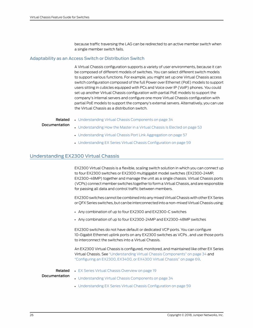
Adaptability as an Access Switch or Distribution Switch
A Virtual Chassis configuration supports a variety of user environments, because it can
be composed of different models of switches. You can select different switch models
to support various functions. For example, youmight set up one Virtual Chassis access
switch configuration composed of the full Power over Ethernet (PoE)models to support
users sitting in cubicles equipped with PCs and Voice over IP (VoIP) phones. You could
set up another Virtual Chassis configuration with partial PoEmodels to support the
company's internal servers and configure onemore Virtual Chassis configuration with
partial PoEmodels to support the company's external servers. Alternatively, you can use
the Virtual Chassis as a distribution switch.
RelatedDocumentation
Understanding Virtual Chassis Components on page 34•
• Understanding How the Master in a Virtual Chassis Is Elected on page 53
• Understanding Virtual Chassis Port Link Aggregation on page 57
• Understanding EX Series Virtual Chassis Configuration on page 59
Understanding EX2300 Virtual Chassis
EX2300 Virtual Chassis is a flexible, scaling switch solution in which you can connect up
to four EX2300 switches or EX2300multigigabit model switches (EX2300-24MP,
EX2300-48MP) together andmanage the unit as a single chassis. Virtual Chassis ports
(VCPs)connectmember switches together to formaVirtualChassis, andare responsible
for passing all data and control traffic betweenmembers.
EX2300switchescannotbecombined intoanymixedVirtualChassiswithotherEXSeries
orQFXSeries switches, but canbe interconnected intoanon-mixedVirtualChassisusing:
• Any combination of up to four EX2300 and EX2300-C switches
• Any combination of up to four EX2300-24MP and EX2300-48MP switches
EX2300 switches do not have default or dedicated VCP ports. You can configure
10-Gigabit Ethernet uplink ports on any EX2300 switches as VCPs , and use those ports
to interconnect the switches into a Virtual Chassis.
An EX2300Virtual Chassis is configured,monitored, andmaintained like other EX Series
Virtual Chassis. See “Understanding Virtual Chassis Components” on page 34 and
“Configuring an EX2300, EX3400, or EX4300 Virtual Chassis” on page 69.
RelatedDocumentation
EX Series Virtual Chassis Overview on page 19•
• Understanding Virtual Chassis Components on page 34
• Understanding EX Series Virtual Chassis Configuration on page 59
Copyright © 2018, Juniper Networks, Inc.26
Virtual Chassis Feature Guide for Switches

Understanding EX3400 Virtual Chassis
EX3400 Virtual Chassis is a flexible, scaling switch solution in which you can connect up
to tenEX3400switches together andmanage theunit as a single chassis. Virtual Chassis
ports (VCPs) connect switches (Virtual Chassis members) together to form a Virtual
Chassis, and are responsible for passing all data and control traffic betweenmembers.
Anymodels of EX3400 switches can be interconnected into an EX3400 Virtual Chassis,
but EX3400 switches cannot be interconnected into a Virtual Chassis with any other
Juniper Networks EX Series or QFX Series switches.
By default, the QFSP+ uplink ports on EX3400 switches are configured as VCPs, or you
can configure any SFP+ uplink module ports on EX3400 switches as VCPs.
NOTE: Uplink ports with SFP tranceivers cannot be used as VCPs tointerconnect EX3400 switches into a Virtual Chassis.
An EX3400Virtual Chassis is configured,monitored, andmaintained like other EX Series
Virtual Chassis. See “Understanding Virtual Chassis Components” on page 34 and
“Configuring an EX2300, EX3400, or EX4300 Virtual Chassis” on page 69.
For general information about EX Series Virtual Chassis, see “EX Series Virtual Chassis
Overview” on page 19.
RelatedDocumentation
EX Series Virtual Chassis Overview on page 19•
• Understanding Virtual Chassis Components on page 34
• Understanding EX Series Virtual Chassis Configuration on page 59
Understanding EX4300 Virtual Chassis
EX4300 Virtual Chassis brings the Virtual Chassis flexible, scaling switch solution to the
JuniperNetworksEX4300EthernetSwitch.Up to tenEX4300switchescanbeconnected
together to form a EX4300 Virtual Chassis that can bemanaged as a single unit.
EX4300 switches can act as member switches in a non-mixed Virtual Chassis, which is
a Virtual Chassis composed entirely of EX4300 switches or EX4300multigigabit model
(EX4300-48MP) switches.
EX4300multigigabit model switches can only participate in an EX4300 Virtual Chassis
with other EX4300 switches in mixedmode, and the other EX4300 switches must be
configuredwith a special option (ieee-clause-82)when settingmixedmode. In this case,
the switches in theRoutingEngine rolemustbemultitigabitmodel switches, andEX4300
switches that are not multigigabit models can only be configured into linecard role.
Multigigabitmodel EX4300 switches cannot interoperate in amixedVirtual Chassiswith
any other types of switches.
27Copyright © 2018, Juniper Networks, Inc.
Chapter 1: Virtual Chassis Overview

EX4300 switches that are not multigigabit models can also be included in the linecard
role in a mixed Virtual Chassis with EX4600 switches or particular QFX Series switches,
and can be included as leaf nodes in a Virtual Chassis Fabric (VCF). For more details on
EX4300member switches inamixedVirtualChassis, see “UnderstandingMixedEXSeries
and QFX Series Virtual Chassis or Virtual Chassis Fabric” on page 46. For information on
EX4300 switches in a VCF, see Virtual Chassis Fabric Overview.
You interconnect EX4300 switches into an EX4300Virtual Chassis using Virtual Chassis
ports (VCPs). VCPs are responsible for passing all data and control traffic between
member switches in the Virtual Chassis. All 40-Gigabit QSFP+ optical ports on EX4300
switches, excluding the multitigabit models, are configured as VCPs by default, and any
10-Gigabit uplink module ports can also be configured into VCPs. You can add new
switches to aVirtual Chassis if the switch is installed in the samebuilding or at a different
sitebecause the long-distanceopticalportscanbeused to interconnectEX4300switches
into the Virtual Chassis.
On EX4300multigigabit models, the four 40-Gbps QSFP+ ports on the rear panel are
dedicated VCPs. These are the only ports on EX4300multigigabit model switches that
can be used as VCPs.
You can increase the VCP bandwidth between any twomember switches by connecting
multiple VCP links between the switches. Whenmultiple VCP links are interconnecting
the same twomember switches, a Link AggregationGroup (LAG) bundle is formedwhen
the links are identical speeds. For instance, if you have four 40-Gigabit links configured
as VCPs betweenmember switches, a LAGwith four member links at 160Gbps of
bandwidth is formed. 10-Gigabit and 40-Gigabit links configured as VCPs cannot be
members of the same LAG, however.
An EX4300Virtual Chassis is configured,monitored, andmaintained like other EX Series
Virtual Chassis. See “Understanding Virtual Chassis Components” on page 34.
RelatedDocumentation
Configuring an EX2300, EX3400, or EX4300 Virtual Chassis on page 69•
• Understanding Virtual Chassis Components on page 34
• Understanding How the Master in a Virtual Chassis Is Elected on page 53
• Understanding Virtual Chassis Port Link Aggregation on page 57
• Understanding EX Series Virtual Chassis Configuration on page 59
Understanding EX4600 Virtual Chassis
EX4600 Virtual Chassis brings the Virtual Chassis flexible, scaling switch solution to the
Juniper Networks EX4600Ethernet Switch. You can connect up to ten EX4600 switches
together to form one EX4600 Virtual Chassis andmanage the unit as a single chassis.
EX4600 switches can act asmember switches in a non-mixed Virtual Chassis—aVirtual
Chassis composed entirely of EX4600 switches—as well as participate as member
switches in amixedVirtual Chassiswith EX4300 switches. Any EX4300 switches except
multigigabit models (EX4300-48MP) can be interconnected with EX4600 switches as
Copyright © 2018, Juniper Networks, Inc.28
Virtual Chassis Feature Guide for Switches

amixed EX4600 Virtual Chassis, but the EX4300 switches cannot be configured into
the Routing Engine role; only EX4600 switches can be in the Routing Engine role.
You configure an EX4600 Virtual Chassis by configuring optical interfaces into Virtual
Chassis ports (VCPs), and using those ports to connect the Virtual Chassis members.
VCPs are responsible for passing all data and control traffic betweenmember switches
in the Virtual Chassis. EX4600 switches do not have any ports that are configured into
VCPs by default, but all 40-Gigabit QSFP+ and 10-Gigabit SFP+ optical ports on an
EX4600 switch can be configured into VCPs.
You can increase the VCP bandwidth between any twomember switches by connecting
multiple VCP links between the switches. Whenmultiple VCP links are interconnecting
the same twomember switches, a Link AggregationGroup (LAG) bundle is formedwhen
the links are identical speeds. For instance, if you have four 40-Gigabit links configured
as VCPs betweenmember switches, a LAGwith four member links at 160Gbps of
bandwidth is formed. 10-Gigabit and 40-Gigabit links configured as VCPs cannot be
members of the same LAG, however.
An EX4600Virtual Chassis is configured,monitored, andmaintained like other EXSeries
Virtual Chassis. See “Understanding Virtual Chassis Components” on page 34.
RelatedDocumentation
Understanding Virtual Chassis Components on page 34•
• Understanding How the Master in a Virtual Chassis Is Elected on page 53
• Understanding Virtual Chassis Port Link Aggregation on page 57
• Understanding EX Series Virtual Chassis Configuration on page 59
Understanding QFX Series Virtual Chassis
This topicdiscussesQFXSeriesVirtualChassis.AQFXSeriesVirtualChassis isa supported
combination of interconnectedQFX3500,QFX3600,QFX5100,QFX5110, QFX5200, and
EX4300 switches operating as one logical device andmanaged as a single chassis.
Switches in a Virtual Chassis are calledmembers of the Virtual Chassis.
This topicdoesnotdiscussVirtualChassis Fabric (VCF). For informationonunderstanding
VCF, see Virtual Chassis Fabric Overview.
This topic includes:
• QFX Virtual Chassis Overview on page 30
• QFX5200 Switches in a Virtual Chassis on page 31
• QFX5110 Switches in a Virtual Chassis on page 31
• QFX5100 Switches in a Virtual Chassis on page 31
• QFX3500 and QFX3600 Switches in a Virtual Chassis on page 33
• EX4300 Switches in a QFX Series Virtual Chassis on page 33
29Copyright © 2018, Juniper Networks, Inc.
Chapter 1: Virtual Chassis Overview

QFX Virtual Chassis Overview
A QFX Series Virtual Chassis is a flexible, scaling switch solution for supported
combinations of QFX3500, QFX3600, QFX5100, QFX5110, and QFX5200 switches.
EX4300 switches can also be included in some configurations of a QFX Series Virtual
Chassis.
InaQFXSeriesVirtualChassis, youcan interconnect standaloneswitches in the following
combinations into one logical device, andmanage the logical device as a single chassis:
• Up to three QFX5200 switches (a non-mixed Virtual Chassis)
• Up to ten QFX5110 switches or a combination of QFX5110 and QFX5100 switches (a
non-mixed Virtual Chassis)
• Up to ten QFX5100 switches (a non-mixed Virtual Chassis)
• Up to tenQFX5100switcheswith any combinationofQFX3500,QFX3600, or EX4300
switches (a mixedmode Virtual Chassis)
• Up to ten QFX3500 switches or QFX3600 switches, or a combination of QFX3500
and QFX3600 switches (a non-mixed Virtual Chassis)
• Up to ten QFX3500 or QFX3600 switches with supported EX4300 switches, or a
combination of all three types of switches (a mixedmode Virtual Chassis)
NOTE: EX4300multigigabit model (EX4300-48MP) switches are notsupported in amixedmode Virtual Chassis with QFX Series switches.
The advantages of connecting multiple switches into a Virtual Chassis include
better-managedbandwidthatanetwork layer, simplifiedconfigurationandmaintenance
becausemultiple devices can bemanaged as a single device, increased fault tolerance
andhighavailability(HA)becauseaVirtual Chassis can remain active andnetwork traffic
can be redirected to other member switches when a single member switch fails, and a
flatter, simplified Layer 2 network topology that minimizes or eliminates the need for
loop prevention protocols such as Spanning Tree Protocol (STP).
You set up a Virtual Chassis by configuring Virtual Chassis ports (VCPs) on themember
switches, and interconnecting the switches using the VCPs . VCPs are responsible for
passing all data and control traffic betweenmember switches in the Virtual Chassis. The
following ports on QFX Series switches that support Virtual Chassis can be configured
into VCPs to form a QFX Series Virtual Chassis:
• Any 40-Gbps QSFP+ ports on QFX5200 switches
• Any 100-Gbps or 40-Gbps QSFP28 ports on QFX5110 switches
• Any non-channelized 40-Gbps QSFP+ ports on QFX3500, QFX3600, QFX5100, or
QFX5110 switches
• Any fixed 10-Gbps SFP+ ports on QFX Series switches with these ports
Copyright © 2018, Juniper Networks, Inc.30
Virtual Chassis Feature Guide for Switches

See EX4300 Switches Hardware Overview for details on the ports on an EX4300 switch
that can be configured into VCPs in a QFX Series Virtual Chassis.
You can increase VCP bandwidth betweenmember switches by configuring multiple
interfaces between the same two switches into VCPs.Whenmultiple VCPs interconnect
the same twomember switches, a Link Aggregation Group (LAG) or bundle is
automatically formed when the VCPs are on interfaces supporting identical speeds. For
example, if you have two 40-Gbps QSFP+ interfaces configured as VCPs between
member switches, a LAGwith twomember links with 80Gbps of total bandwidth is
formed. However, 10-Gbps SFP+ and 40-Gbps QSFP+ interfaces configured as VCPs
will not becomemembers of the same VCP LAG.
QFX5200 Switches in a Virtual Chassis
Starting in Junos OS Release 17.3R2, Virtual Chassis is supported on QFX5200 switches.
You can interconnect up to three QFX5200 switches into a QFX5200 Virtual Chassis.
QFX5200switches cannotbecombinedwithother typesof switches in aVirtualChassis.
The following QFX5200 switches are supported in a QFX5200 Virtual Chassis:
• QFX5200-32C
QFX5110 Switches in a Virtual Chassis
Starting in Junos OS Release 17.3R1, Virtual Chassis is supported on QFX5110 switches.
You can interconnect up to ten QFX5110 switches or a combination of QFX5110 and
QFX5100switches intoaQFX5110VirtualChassis. All switchescan run the samesoftware
image, and you do not need to configure mixedmode.
The followingQFX5110andQFX5100switchesare supported inaQFX5110VirtualChassis:
• QFX5110-32Q
• QFX5110-48S
• QFX5100-24Q
• QFX5100-48S
• QFX5100-48T
Starting in Junos OS Release 17.3R2, QFX5100-48T switches can be included in a
QFX5110 Virtual Chassis.
• QFX5100-96S
QFX5100 Switches in a Virtual Chassis
Starting in Junos OS Release 13.2X51-D20, Virtual Chassis is supported on QFX5100
switches. You can interconnect up to ten switches into a QFX5100 Virtual Chassis that
can include any combination of QFX5100, QFX3500, QFX3600, and EX4300 switches.
31Copyright © 2018, Juniper Networks, Inc.
Chapter 1: Virtual Chassis Overview

NOTE: In JunosOS release 13.2X51-D20, you can interconnect only up to fourQFX5100-96S switches in a non-mixed QFX5100 Virtual Chassis. Startingin Junos OS release 13.2X51-D25, you can configure up to ten QFX5100-96Sswitches into amixed or non-mixed QFX Series Virtual Chassis.
The followingQFX5100 switches are supported in a non-mixedQFX5100Virtual Chassis
or a mixed QFX5100 Virtual Chassis (QFX5100 switches with QFX3500, QFX3600, or
EX4300 switches):
• QFX5100-24Q
• QFX5100-48S
• QFX5100-48T
• QFX5100-96S
NOTE: QFX5100-24Q switches should be configured as the Routing Enginerole members in amixed QFX5100 Virtual Chassis.
QFX5100 switches can also be part of a QFX5110 Virtual Chassis, which can include a
combination of up to ten QFX5110 and QFX5100 switches. For a QFX5100 switch to
participate in aQFX5110Virtual Chassis, the switchmust have the samesoftware version
and image installed as the software running on the QFX5110 switches in the Virtual
Chassis. You do not need to configure mixedmode. In a QFX5110 Virtual Chassis, we
recommend to use QFX5110 switches in the master and backup Routing Engine roles,
and QFX5100 switches only in the line-card role.
The following QFX5100 switches are supported in a QFX5110 Virtual Chassis:
• QFX5100-24Q
• QFX5100-48S
• QFX5100-48T
Starting in Junos OS Release 17.3R2, QFX5100-48T switches can be included in a
QFX5110 Virtual Chassis.
• QFX5100-96S
CAUTION: AQFX5100 switch running a Junos OS software image with“-qfx-5-” in the package filenamemust first be upgraded to a Junos OSsoftware image with “-qfx-5e-” in the package filename before it can beaddedtoaQFX5110VirtualChassisorVCF.See“UpgradingaQFX5100SwitchwithaUSBDevice to JoinaQFX5110VirtualChassis orVirtualChassis Fabric”on page 135.
Copyright © 2018, Juniper Networks, Inc.32
Virtual Chassis Feature Guide for Switches

QFX3500 andQFX3600 Switches in a Virtual Chassis
Virtual Chassis is supported on QFX3500 and QFX3600 series switches. To be included
in a Virtual Chassis, QFX3500 and QFX3600 series switches must be configured as
standalone switches and not as QFX node devices in a QFabric system.
QFX3500 and QFX3600 devicesmust be running a version of Junos OS for QFX devices
that supportsVirtualChassis, andcanbe inaVirtualChassiswithup to ten totalmembers
including QFX3500 or QFX3600 switches only, or any combination of QFX3500,
QFX3600, QFX5100, and EX4300 switches.
NOTE: EX4300multigigabit model (EX4300-48MP) switches are notsupported in amixed Virtual Chassis with QFX Series switches.
EX4300 Switches in a QFX Series Virtual Chassis
Virtual Chassis is supported on EX4300 switches. Starting in Junos OS Release
13.2X51-D20, EX4300 switches except multigigabit models (EX4300-48MP) can be
interconnected into a QFX Series Virtual Chassis with QFX3500 switches, QFX3600
switches, and QFX5100 switches.
A mixed or non-mixed QFX Series Virtual Chassis that includes EX4300 switches can
contain up to ten total member switches including any combination of QFX3500,
QFX3600, and QFX5100 switches with EX4300 switches.
33Copyright © 2018, Juniper Networks, Inc.
Chapter 1: Virtual Chassis Overview

Release History Table DescriptionRelease
Starting in Junos OS Release 17.3R2, Virtual Chassis is supported onQFX5200 switches.
17.3R2
Starting in JunosOSRelease 17.3R2,QFX5100-48Tswitchescanbe includedin a QFX5110 Virtual Chassis.
17.3R2
Starting in JunosOSRelease 17.3R1, VirtualChassis is supportedonQFX5110switches.
17.3R1
Starting in Junos OS release 13.2X51-D25, you can configure up to tenQFX5100-96S switches into amixed or non-mixed QFX Series VirtualChassis.
13.2X53-D25
Starting in Junos OS Release 13.2X51-D20, Virtual Chassis is supported onQFX5100 switches.
13.2X51-D20
In Junos OS release 13.2X51-D20, you can interconnect only up to fourQFX5100-96S switches in a non-mixed QFX5100 Virtual Chassis.
13.2X51-D20
Starting in Junos OS Release 13.2X51-D20, EX4300 switches exceptmultigigabit models (EX4300-48MP) can be interconnected into a QFXSeries Virtual Chassis with QFX3500 switches, QFX3600 switches, andQFX5100 switches.
13.2X51-D20
RelatedDocumentation
Understanding Virtual Chassis Components on page 34•
• Configuring a QFX Series Virtual Chassis (CLI Procedure) on page 84
Understanding Virtual Chassis Components
This topic describes the components of an EX series or a QFX Series Virtual Chassis.
• An EX Series Virtual Chassis is a supported combination of standalone EX Series
switches interconnected andmanaged as a single chassis. This topic applies to all EX
Series Virtual Chassis except EX8200 Virtual Chassis. (See Understanding EX8200
Virtual Chassis Components for information about EX8200 Virtual Chassis.)
NOTE: For deployments with EX9200 switches, we recommend planningor moving to MC-LAG or Junos Fusion Enterprise architectures rather thanusing a Virtual Chassis. We do not recommend using EX9200 switches ina Virtual Chassis.
• A QFX Series Virtual Chassis is a supported combination of standalone QFX3500,
QFX3600, QFX5100, QFX5110, or QFX5200 switches interconnected andmanaged
asasinglechassis. EX4300switches (excludingmultigigabitmodels (EX4300-48MP))
can also be interconnected into amixedVirtual ChassiswithQFX3500,QFX3600, and
QFX5100 switches.
Copyright © 2018, Juniper Networks, Inc.34
Virtual Chassis Feature Guide for Switches

This topicdoesnotdiscussVirtualChassis Fabric components. For informationonVirtual
Chassis Fabric components, see Understanding Virtual Chassis Fabric Components.
This topic covers:
• Maximum Switch Support on page 35
• Virtual Chassis Ports (VCPs) on page 38
• Master Routing Engine Role on page 41
• Backup Routing Engine Role on page 42
• Linecard Role on page 43
• Member Switch and Member ID on page 43
• Mastership Priority on page 44
• Virtual Chassis Identifier (VCID) on page 45
MaximumSwitch Support
Themaximum number of switches that a Virtual Chassis supports varies by Virtual
Chassis andmight also depend on the Junos OS release running on the Virtual Chassis.
• MaximumNumber of Switches in an EX Series Virtual Chassis on page 35
• Maximum Switch Support in a QFX Series Virtual Chassis (Including Mixed Virtual
Chassis with EX Series Switches) on page 37
MaximumNumber of Switches in an EX Series Virtual Chassis
Table 4 on page 35 lists the maximummember switch support by EX Series Virtual
Chassis and Junos OS release.
Table 4: MaximumMember Switch Support for Virtual Chassis by Junos OS Release
Initial Junos OS ReleaseMaximumMember Switch Support
12.2R1—Initial release. Support for up to fourEX2200member switches.
EX2200 Virtual Chassis
15.1X53-D50—Initial release. Support for up tofour EX2300member switches.
18.1R2–Support for up to four multigigabitEX2300 (EX2300-24MP and EX2300-48MP)member switches.
EX2300 Virtual Chassis
11.3R1—Initial release. Support for up to sixEX3300member switches
12.2R1—Starting in Junos OS Release 12.2R1, anEX3300 Virtual Chassis can support up to tenEX3300member switches.
EX3300 Virtual Chassis
15.1X53-D50—Initial release. Support for up toten EX3400member switches
EX3400 Virtual Chassis
35Copyright © 2018, Juniper Networks, Inc.
Chapter 1: Virtual Chassis Overview

Table 4: MaximumMember Switch Support for Virtual Chassis by Junos OSRelease (continued)
Initial Junos OS ReleaseMaximumMember Switch Support
9.0R1—Initial release. Support for up to tenEX4200member switches
EX4200 Virtual Chassis
13.2X50-D10—Initial release. Support for up toten EX4300member switches
13.2X50-D20—Starting in Junos OS Release13.2X50-D20, EX4300 switch support wasadded in a mixed QFX Series Virtual Chassis orin a VCF.
18.2R1—Starting in JunosOSRelease 18.2R1withthe introductionof EX4300multigigabitmodelswitches (EX4300-48MP), an EX4300 VirtualChassis can contain up to ten EX4300multigigabit model switches as a non-mixedVirtual Chassis or a combination of EX4300multigigabitmodel switcheswithotherEX4300switches as amixed EX4300 Virtual Chassis.
EX4300 Virtual Chassis
11.1R1—Initial release. Support for up to twoEX4500 switches
11.4R1—Support for up to ten EX4500memberswitches
EX4500 Virtual Chassis
12.2R1—Initial release. Support for up to tenEX4550 switches
EX4550 Virtual Chassis
13.2X51-D25—Initial release. Support for up toten EX4600 switches
EX4600 Virtual Chassis
11.1R1—Initial release. Support for up to twoEX4500 switches and up to eight EX4200switches
11.2R1—Support forup tonineEX4200switches
11.4R1—Support for up tonineEX4500switches
Mixed EX4200 and EX4500 Virtual Chassis
12.2R1—Initial release.Support for up to ten totalEX4200 and EX4550 switches
Mixed EX4200 and EX4550 Virtual Chassis
12.2R1—Initial release.Support for up to ten totalEX4200, EX4500, and EX4550 switches
Mixed EX4200, EX4500, and EX4550 VirtualChassis
Copyright © 2018, Juniper Networks, Inc.36
Virtual Chassis Feature Guide for Switches
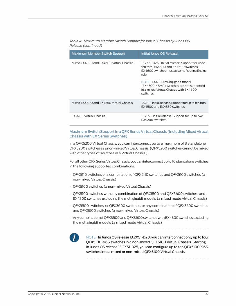
Table 4: MaximumMember Switch Support for Virtual Chassis by Junos OSRelease (continued)
Initial Junos OS ReleaseMaximumMember Switch Support
13.2X51-D25—Initial release. Support for up toten total EX4300 and EX4600 switches.EX4600switchesmustassumeRoutingEnginerole.
NOTE: EX4300multigigabit model(EX4300-48MP) switches are not supportedin a mixed Virtual Chassis with EX4600switches.
Mixed EX4300 and EX4600 Virtual Chassis
12.2R1—Initial release.Support for up to ten totalEX4500 and EX4550 switches
Mixed EX4500 and EX4550 Virtual Chassis
13.2R2—Initial release. Support for up to twoEX9200 switches.
EX9200 Virtual Chassis
MaximumSwitchSupport inaQFXSeriesVirtualChassis (IncludingMixedVirtualChassis with EX Series Switches)
In a QFX5200 Virtual Chassis, you can interconnect up to amaximum of 3 standalone
QFX5200switchesasanon-mixedVirtualChassis. (QFX5200switchescannotbemixed
with other types of switches in a Virtual Chassis.)
Forall otherQFXSeriesVirtualChassis, youcan interconnectup to 10standaloneswitches
in the following supported combinations:
• QFX5110 switches or a combination of QFX5110 switches and QFX5100 switches (a
non-mixed Virtual Chassis)
• QFX5100 switches (a non-mixed Virtual Chassis)
• QFX5100 switches with any combination of QFX3500 and QFX3600 switches, and
EX4300 switches excluding the multigigabit models (a mixedmode Virtual Chassis)
• QFX3500 switches, or QFX3600 swtiches, or any combination of QFX3500 switches
and QFX3600 switches (a non-mixed Virtual Chassis)
• AnycombinationofQFX3500andQFX3600switcheswithEX4300switchesexcluding
the multigigabit models (a mixedmode Virtual Chassis)
NOTE: In JunosOS release 13.2X51-D20, you can interconnect only up to fourQFX5100-96S switches in a non-mixed QFX5100 Virtual Chassis. Startingin Junos OS release 13.2X51-D25, you can configure up to ten QFX5100-96Sswitches into amixed or non-mixed QFX5100 Virtual Chassis.
37Copyright © 2018, Juniper Networks, Inc.
Chapter 1: Virtual Chassis Overview

Virtual Chassis Ports (VCPs)
You set up a Virtual Chassis by configuring Virtual Chassis ports (VCPs) on themember
switches, and interconnecting the switches using the VCPs. VCPs are responsible for
passing all data and control traffic betweenmember switches in the Virtual Chassis.
• Virtual Chassis Port Options on page 38
• Automatic Virtual Chassis Port (VCP) Conversion on page 39
• Virtual Chassis Port Link Aggregation Groups on page 41
Virtual Chassis Port Options
Some switches have dedicated VCPs; these ports can only be used as VCPs and cannot
be reconfigured as network ports. Dedicated VCPs allow you to interconnect switches
without requiring any additional interface configuration.
Some switches have ports that are configured as VCPs by default. You do not need to
explicitly configure those as VCPs to use them to interconnect those switches into a
Virtual Chassis.
Most switches have optical or uplink ports that can also be configured as VCPs.
To interconnect switches that do not have dedicated or default-configured VCPs, or to
interconnect switches across greater distances than allowed by a dedicated VCP
connection, youmust configure the VCPs. Also, when adding switches to an existing
VirtualChassis, oraddingnewredundant linksbetweenexistingmembers, if theautomatic
VCP conversion feature is enabled, under the right conditions the ports on both sides of
the connection will convert into VCPs automatically (see “Automatic Virtual Chassis
Port (VCP) Conversion” on page 39).
Table 5 on page 38 summarizes the available VCP options on switches in an EX Series
or QFX Series Virtual Chassis. For complete details on where dedicated VCPs,
default-configuredVCPs, or ports that canbeconfiguredasVCPsare locatedonaswitch,
andwhat transceiversandcablesare supported touse forVCPconnectionson theswitch,
see the hardware documentation for that type of switch.
Table 5: VCPOptions by Switch Type
Ports that can be configured as VCPsDefault VCPsDedicated VCPsSwitch
Any uplink ports
All RJ-45 interfaces, including built-in network portswith 10/100/1000BASE-TGigabit Ethernet connectorsand 1000BASE-T RJ-45 transceivers
NoneNoneEX2200
Uplink ports with SFP+ tranceivers
NOTE: You cannot use ports with SFP transceivers asVCPs on EX2300 switches to form a Virtual Chassis.
NoneNoneEX2300(includingmultigigabitEX2300models)
Any uplink portsUplink ports 2 and 3NoneEX3300
Copyright © 2018, Juniper Networks, Inc.38
Virtual Chassis Feature Guide for Switches

Table 5: VCPOptions by Switch Type (continued)
Ports that can be configured as VCPsDefault VCPsDedicated VCPsSwitch
Any SFP+ uplink ports
NOTE: You cannot use ports with SFP transceivers asVCPs on EX3400 switches to form a Virtual Chassis.
All QSFP+ uplink portsNoneEX3400
Anyuplinkmoduleports (SFP,SFP+,orXFP)or throughan SFP+ port on the EX4200-24F switch
NOTE: You cannot set a 1000BASE-T copper SFPtransceiver (EX-SFP-1GE-T) connection as a VCP onEX4200 switches.
None2 ports on rearpanel
EX4200
Any uplink ports installed with SFP+ or QSPF+transceivers
All QSFP+ portsNoneEX4300
NoneNone440-GbpsQSFP+portson rearpanel
EX4300MultigigabitModels(EX4300-48MP)
Any SFP+ port
NOTE: YoucannotuseSFP+uplinkports installedwith1000BASE-TcopperSFP transceivers (EX-SFP-1GE-T)as VCP connections on EX4500 and EX4550 switches.
NoneTwo ports on theVirtual Chassismodule
EX4500 andEX4550
Any SFP+ and QSFP+ portsNoneNoneEX4600
Any non-channelized 40-Gbps QSFP+ interfacesNoneNoneQFX3500 andQFX3600
Any non-channelized 40-Gbps QSFP+ interfacesNoneNoneQFX5100
Any 100-Gbps or 40-Gbps QSFP28 ports
Any non-channelized 40-Gbps QSFP+ interfaces
NoneNoneQFX5110
Any 40-Gbps QSFP+ portsNoneNoneQFX5200
All supported SFP, SFP+, and XFP uplink connections between EX4200, EX4500, and
EX4550 switches can be configured as VCPs.
QSFP+ interfaces that have been channelized into SFP+ interfaces using a breakout
cable cannot be configured into VCPs.
Automatic Virtual Chassis Port (VCP) Conversion
When the automatic VCP conversion feature is enabled and you cable a new link from
anewswitchbeingadded intoanexistingVirtualChassis, or adda redundant linkbetween
twomembers of a Virtual Chassis, ports that can be VCPs are automatically converted
into VCPs under the following conditions:
39Copyright © 2018, Juniper Networks, Inc.
Chapter 1: Virtual Chassis Overview

• Link Layer Discovery Protocol (LLDP) or LLDP-Media Endpoint Discovery (LLDP-MED)
is enabled on the interfaces for the members on both ends of the new link. The two
sides exchange LLDP packets to accomplish the port conversion.
• The Virtual Chassismust be preprovisionedwith the switches on both sides of the link
alreadyconfigured in themembers list of theVirtualChassis using the setvirtual-chassis
member command.
• The interfaces for theports onboth endsof the link are not already configuredasVCPs.
Both sides of the link must be in the same state to handshake and establish the VCP
link.
UsingautomaticVCPconversionwhenaddingaswitch toapreprovisionedVirtualChassis
is also referred to as autoprovisioning the newmember.
Ports thatareconfiguredasVCPsbydefault onaswitchor thatwerepreviously configured
into VCPsmust be converted back into network ports using the request virtual-chassis
vc-port delete command for the port to be eligible for automatic VCP conversion. A port
that has been automatically converted into a VCP is not automatically converted back
into a network port when you remove a switch fromaVirtual Chassis and disconnect the
link.
Automatic VCP conversion is enabled by default on all Virtual Chassis, except in the
following cases:
• Starting in Junos OS Releases 15.1R7 and 14.1X53-D47, in EX2200, EX3300, EX4200,
EX4500, andEX4550VirtualChassis, automaticVCPconversion is disabledbydefault.
If desired, you can enable the feature by configuring the auto-conversion statement at
the [edit virtual-chassis] hierarchy level on the Virtual Chassis.
CAUTION: WhenautomaticVCPconversion is enabled in aVirtual Chassiswith switches that have dedicated VCPs (EX4200, EX4500, or EX4550Virtual Chassis), if network or uplink ports are automatically convertedinto VCPs to create a redundant link with a dedicated VCP connectionbetween the same two Virtual Chassis members, youmust reboot theVirtual Chassis to avoid creating a traffic loop within the Virtual Chassis.(The same issue can occur even if the ports aremanually converted intoVCPs to create the redundant VCP link with a dedicated VCP link, so thereboot is required to avoid traffic looping in that case as well.)
• Starting in Junos OS Releases 14.1X53-D47, 17.4R2, and 18.1R3, in EX4300, EX4600,
and QFX Series Virtual Chassis (which have the automatic VCP conversion feature
enabled by default), you can choose to disable the feature by configuring the
no-auto-conversion statementat the [edit virtual-chassis]hierarchy level on theVirtual
Chassis. To return to thedefault behavior to reenableautomaticVCPconversion, delete
the no-auto-conversion statement from the configuration.
Copyright © 2018, Juniper Networks, Inc.40
Virtual Chassis Feature Guide for Switches

Virtual Chassis Port Link Aggregation Groups
You can increase VCP bandwidth betweenmember switches by configuring multiple
interfaces between the same two switches into VCPs.Whenmultiple VCPs interconnect
the same twomember switches, a Link Aggregation Group (LAG) or bundle is
automatically formed when the VCPs are on interfaces supporting identical speeds. For
example, if you have two 40-Gbps QSFP+ interfaces configured as VCPs between
member switches, a LAGwith twomember links with 80-Gbps of total bandwidth is
formed. However, 10-Gigabit SFP+ and 40-Gbps QSFP+ interfaces configured as VCPs
will not becomemembers of the same LAG. See “Understanding Virtual Chassis Port
Link Aggregation” on page 57.
Master Routing Engine Role
In a Virtual Chassis, eachmember switch is assigned one of two roles: Routing Engine
role or linecard role, and for Routing Engine role, receives a further designation as the
master or backup Routing Engine.
Themember that functionsas themaster in theRoutingEngine role in theVirtualChassis:
• Manages the member switches.
• Runs Junos OS for the switches as amaster Routing Engine.
• Runs the chassis management processes and control protocols.
• Represents all the member switches interconnected within the Virtual Chassis
configuration. (Thehostnameandother properties that youassign to this switchduring
setup apply to all members of the Virtual Chassis configuration.)
In a preprovisioned configuration, one of the twomembers assigned as routing-engine
functions as the master member. The selection of which member assigned as
routing-engine functions as master and which as backup is determined by the software
based on themaster election algorithm. See “Understanding How theMaster in a Virtual
Chassis Is Elected” on page 53.
In a configuration that is not preprovisioned, the selection of the master and backup is
determined by themastership priority value and secondary factors in themaster election
algorithm.
All switches that are not assigned themaster or backup Routing Engine role function in
the linecard role.
Use the following guidelines for assigning Routing Engine roles to the switches in amixed
Virtual Chassis:
• In any mixed Virtual Chassis configuration that includes EX4200 switches, EX4500
switches, or EX4550 switches, any switch can be configured in any role in any
configuration.
• In a mixed EX4300 Virtual Chassis composed of EX4300multigigabit model
(EX4300-48MP)andotherEX4300model switches, theswitches in theRoutingEngine
role should always be EX4300multigigabit model switches.
41Copyright © 2018, Juniper Networks, Inc.
Chapter 1: Virtual Chassis Overview

• In a mixed EX4600 Virtual Chassis with EX4300 switches, an EX4600 switch must
assume themaster role.
• In a mixed QFX Series Virtual Chassis made up of QFX5100 switches with QFX3500,
QFX3600, or EX4300 switches, we recommend configuring QFX5100 switches into
theRoutingEngine role. If themixedVirtualChassisdoesnotcontainQFX5100switches,
we recommend configuring QFX3500 or QFX3600 switches into the Routing Engine
role.
• In a QFX5110 Virtual Chassis with QFX5110 and QFX5100 switches, we recommend
configuring only QFX5110 switches into the Routing Engine role.
Backup Routing Engine Role
Themember that functions in the backup Routing Engine role in a Virtual Chassis:
• Maintains a state of readiness to take over themaster Routing Engine role if themaster
fails.
• Runs Junos OS for the switches as a backup Routing Engine.
• Synchronizes with themaster in terms of protocol states, forwarding tables, and other
information, so that it is prepared topreserve routing informationandmaintain network
connectivity without disruption in case the master is unavailable.
Youmust have at least twomember switches in theVirtual Chassis configuration in order
to have a backup Routing Engine member.
In a preprovisioned configuration, one of the twomembers assigned as routing-engine
functions in the backup role. The selection of whichmember assigned as routing-engine
functions as master and which as backup is determined by the software based on the
master election algorithm. See “Understanding How the Master in a Virtual Chassis Is
Elected” on page 53.
In a configuration that is not preprovisioned, the selection of the master and backup is
determined by themastership priority value and secondary factors in themaster election
algorithm.
Use the following guidelines for assigning Routing Engine roles to the switches in amixed
Virtual Chassis:
• In any mixed Virtual Chassis configuration that includes EX4200 switches, EX4500
switches, or EX4550 switches, any switch can be configured in any role in any
configuration.
• In a mixed EX4300 Virtual Chassis composed of EX4300multigigabit model
(EX4300-48MP) and other EX4300model switches, the switches in the master and
backup Routing Engine roles should always be EX4300multigigabit model switches.
• In a mixed EX4600 Virtual Chassis with EX4300 switches, we strongly recommend
configuring an EX4600 switch into the backup role. A mixed EX4600 and EX4300
VirtualChassismustuseanEX4600memberswitch in themaster role, andconfiguring
an EX4600 switch into the backup role ensures that the Virtual Chassis remains up
after a switchover event.
Copyright © 2018, Juniper Networks, Inc.42
Virtual Chassis Feature Guide for Switches

• In a mixed QFX Series Virtual Chassis made up of QFX5100 switches with QFX3500,
QFX3600, or EX4300 switches, we recommend configuring the QFX5100 switches
into the Routing Engine role. If the mixed Virtual Chassis does not contain QFX5100
switches,we recommendconfiguringQFX3500orQFX3600switches into theRouting
Engine role.
• In a QFX5110 Virtual Chassis with QFX5110 and QFX5100 switches, we recommend
configuring only QFX5110 switches into the Routing Engine role.
Linecard Role
Amember that functions in the linecard role in a Virtual Chassis:
• Runs only a subset of Junos OS.
• Does not run the chassis control protocols.
• Can detect certain error conditions (such as an unplugged cable) on any interfaces
that have been configured on it through themaster.
The Virtual Chassis configuration must have at least three members in order to include
a linecard member.
In apreprovisioned configuration, you canexplicitly configure amemberwith the linecard
role, which makes it ineligible for functioning as amaster or backup Routing Engine.
Inaconfiguration that is notpreprovisioned, themembers thatarenot selectedasmaster
orbackup functionas linecardmembersof theVirtualChassis configuration.Theselection
of the master and backup is determined by themastership priority value and secondary
factors in themaster election algorithm. A switchwith amastership priority of 0 is always
in the linecard role.
Any switch can function in the linecard role in a mixed or non-mixed Virtual Chassis.
Use the followingguidelines forassigningRoutingEngineand linecard roles to theswitches
in a QFX Series Virtual Chassis:
• In a mixed QFX Series Virtual Chassis made up of QFX5100 switches with QFX3500,
QFX3600, or EX4300 switches, we recommend configuring the QFX5100 switches
into the Routing Engine role. If the mixed Virtual Chassis does not contain QFX5100
switches,we recommendconfiguringQFX3500orQFX3600switches into theRouting
Engine role.
• In a QFX5110 Virtual Chassis made up of QFX5110 and QFX5100 switches, we
recommend configuring only QFX5110 switches into the Routing Engine role.
Member Switch andMember ID
Each standalone switch that supports Virtual Chassis is a potential member of a Virtual
Chassis configuration. When one of those switches is powered on, it receives a member
ID that canbe seenby viewing the front-panel LCDor by entering the showvirtual-chassis
command. If the switch is powered on as a standalone switch, that member’s member
ID is always0.When the switch is interconnectedwith other switches in a Virtual Chassis
43Copyright © 2018, Juniper Networks, Inc.
Chapter 1: Virtual Chassis Overview

configuration, its member ID is assigned by themaster based on various factors, such as
the order in which the switch was added to the Virtual Chassis configuration or the
member ID assigned by a preprovisioned configuration. See “Understanding How the
Master in a Virtual Chassis Is Elected” on page 53.
If theVirtualChassis configurationpreviously includedamember switchand thatmember
was physically disconnected or removed from the Virtual Chassis configuration, its
member ID is not available for assignment aspart of the standard sequential assignment
by the master. For example, youmight have a Virtual Chassis configuration composed
of member 0, member 2, andmember 3, becausemember 1 was removed. When you
add another member switch and power it on, the master assigns it as member 4.
Themember IDdistinguishes thememberswitches fromoneanother.Youusethemember
ID:
• To assign amastership priority value to amember switch
• To configure interfaces for a member switch (The function is similar to that of a slot
number on Juniper Networks routers.)
• To apply some operational commands to amember switch
• To display status or characteristics of a member switch
Mastership Priority
In aconfiguration that is notpreprovisioned, youcandesignate the role (masterorbackup
Routing Engine role, or linecard role) that a member switch assumes by configuring its
mastership priority (from 0 through 255). Themastership priority value is the factor in
the master election algorithmwith the highest precedence for selecting the master of
the Virtual Chassis configuration. A switch with amastership priority of 0 never assumes
the backup or master Routing Engine role.
The default value for mastership priority is 128. When a standalone switch is powered
on, it receives the default mastership priority value. Because it is the only member of the
Virtual Chassis configuration, it is also the master. When you interconnect a standalone
switch to an existing Virtual Chassis configuration (which implicitly includes its own
master), we recommend that you explicitly configure the mastership priority of the
members that you want to function as the master and backup.
NOTE: Configuring the samemastership priority value for both themasterandbackuphelps toensureasmooth transition frommaster tobackupwhenthemaster becomes unavailable. It prevents the original master frompreempting control from the backup when the backup has taken control ofthe Virtual Chassis configuration because the original master becameunavailable.
In a preprovisioned configuration, you assign the role of eachmember switch.
Copyright © 2018, Juniper Networks, Inc.44
Virtual Chassis Feature Guide for Switches
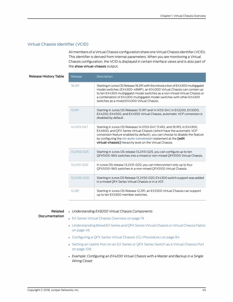
Virtual Chassis Identifier (VCID)
AllmembersofaVirtualChassis configurationshareoneVirtualChassis identifier (VCID).
This identifier is derived from internal parameters. When you are monitoring a Virtual
Chassis configuration, the VCID is displayed in certain interface views and is also part of
the show virtual-chassis output.
Release History Table DescriptionRelease
Starting in JunosOSRelease 18.2R1with the introductionofEX4300multigigabitmodel switches (EX4300-48MP), an EX4300 Virtual Chassis can contain upto ten EX4300multigigabit model switches as a non-mixed Virtual Chassis ora combination of EX4300multigigabit model switches with other EX4300switches as amixed EX4300 Virtual Chassis.
18.2R1
Starting in Junos OS Releases 15.1R7 and 14.1X53-D47, in EX2200, EX3300,EX4200, EX4500, and EX4550 Virtual Chassis, automatic VCP conversion isdisabled by default.
15.1R7
Starting in Junos OS Releases 14.1X53-D47, 17.4R2, and 18.1R3, in EX4300,EX4600, and QFX Series Virtual Chassis (which have the automatic VCPconversion feature enabled by default), you can choose to disable the featureby configuring the no-auto-conversion statement at the [editvirtual-chassis] hierarchy level on the Virtual Chassis.
14.1X53-D47
Starting in Junos OS release 13.2X51-D25, you can configure up to tenQFX5100-96S switches into amixed or non-mixed QFX5100 Virtual Chassis.
13.2X53-D25
In Junos OS release 13.2X51-D20, you can interconnect only up to fourQFX5100-96S switches in a non-mixed QFX5100 Virtual Chassis.
13.2X51-D20
Starting in JunosOSRelease 13.2X50-D20, EX4300switch supportwasaddedin a mixed QFX Series Virtual Chassis or in a VCF.
13.2X50-D20
Starting in Junos OS Release 12.2R1, an EX3300 Virtual Chassis can supportup to ten EX3300member switches.
12.2R1
RelatedDocumentation
Understanding EX8200 Virtual Chassis Components•
• EX Series Virtual Chassis Overview on page 19
• UnderstandingMixedEXSeriesandQFXSeriesVirtualChassisorVirtualChassis Fabric
on page 46
• Configuring a QFX Series Virtual Chassis (CLI Procedure) on page 84
• Setting an Uplink Port on an EX Series or QFX Series Switch as a Virtual Chassis Port
on page 108
• Example: Configuring an EX4200 Virtual Chassis with a Master and Backup in a Single
Wiring Closet
45Copyright © 2018, Juniper Networks, Inc.
Chapter 1: Virtual Chassis Overview
• Example: Configuring an EX4500 Virtual Chassis with a Master and Backup in a Single
Wiring Closet
• Example: Configuring an EX4200 Virtual Chassis Using a Preprovisioned Configuration
File
UnderstandingMixedEXSeriesandQFXSeriesVirtualChassisorVirtualChassisFabric
This topic describes the requirements for a mixed Virtual Chassis or a mixed Virtual
Chassis Fabric (VCF).
Amixed Virtual Chassis includes two or more types of EX Series switches, two or more
typesofQFXSeries switches, or a supportedcombinationofEXandQFXSeries switches,
where architectural differences require the Virtual Chassis to be configured into mixed
mode for the switches to interoperate.
A Virtual Chassis composed of all the same type of switch can usually operate as a
non-mixed Virtual Chassis, which does not require you to set mixedmode. However, the
followingVirtualChassis that includedifferentmodelsof the sameproductmustoperate
in mixedmode due to architecture differences between the different models:
• AnEX4300VirtualChassis composedofEX4300multigigabitmodel (EX4300-48MP)
switches mixed with any other EX4300model switches
NOTE: AnEX4300VirtualChassisoperatesasanon-mixedVirtualChassisif it is composedofonlyEX4300multigigabitmodel switches,or composedof any combination of any other EX4300 switches (excluding themultigigabit models).
The following combinations of different switch types can be interconnected into a
non-mixed Virtual Chassis that does not require you to set mixedmode because the
switches run the same software image when in a Virtual Chassis:
• An EX Series Virtual Chassis composed of only EX4500 and EX4550 switches
• A QFX Series Virtual Chassis composed of only QFX3500 and QFX3600 switches
• A QFX5110 Virtual Chassis composed of QFX5110 and supported QFX5100 switches
QFX5200,EX3400,EX3300,EX2300,andEX2200switchescannotbepartofanymixed
Virtual Chassis. Multigigabit EX2300 switches can form a Virtual Chassis composed of
only EX2300multigigabit switches, and cannot bemixed with other EX2300 switches
in a Virtual Chassis.
A VCF can be based on either QFX5110 switches as the spinemembers (aQFX5110 VCF),
or QFX5100 switches as the spine members (aQFX5100 VCF). A mixed VCF is any VCF
that includes two or more types of member switches in supported combinations that
require you to configure mixedmode for the switches to interoperate in a VCF.
Copyright © 2018, Juniper Networks, Inc.46
Virtual Chassis Feature Guide for Switches

• Amixed QFX5100 VCF is a VCF with QFX5100 spine members that includes any
combination of EX4300 (excluding themultigigabit models), QFX3500, QFX3600, or
QFX5100 switches as leaf members, and requires all members to be configured into
mixedmode. A VCF with only QFX5100members is a non-mixed QFX5100 VCF and
should not havemixedmode configured on anymembers.
• AQFX5110 VCF is a VCF with QFX5110-32Q spine members and any combination of
supportedQFX5110 andQFX5100 switches as leafmembers. AQFX5110VCF is always
a non-mixed VCF because the two types of switches run the same software image
when interconnected into a VCF, and you do not need to configure mixedmode for
them to interoperate in a VCF.
NOTE: The optimal QFX5110 VCF topology is to use QFX5110 switches only,and the optimal QFX5100 VCF topology is to use QFX5100 switches only. Ineach of these topologies, a VCF composed entirely of the base VCF devicessupports the largest breadth of features at the highest scalability while alsosupporting the highest number of high-speed interfaces.
• Virtual Chassis Fabric Summary on page 47
• Understanding Mixed and Non-Mixed Virtual Chassis Fabric on page 48
• Virtual Chassis Summary for QFX5200, QFX5110, QFX5100, QFX3600, QFX3500,
EX4600, and EX4300 Switches on page 49
• Understanding the Routing Engine Role in a Virtual Chassis With Different Types of
Switches on page 50
• Understanding QFX5100 and QFX5110 Switches in a Virtual Chassis on page 51
• UnderstandingEX4300,QFX3500,QFX3600,andQFX5100Switches inaMixedVirtual
Chassis on page 51
• Understanding Mixed EX4300 and EX4600 Virtual Chassis on page 52
• Understanding EX4300Multigigabit and Other EX4300Model Switches in a Mixed
EX4300 Virtual Chassis on page 52
• Understanding EX4200, EX4500, and EX4550 Switches in a Mixed Virtual
Chassis on page 52
Virtual Chassis Fabric Summary
Table 6 on page 48 provides a high-level overview of the permitted hardware allowed in
the Routing Engine and line-card roles of supportedmixed and non-mixed VCF
configurations. The switches in the Routing Engine role must be spine devices in a VCF
topology. The table also includes license requirements and supported configuration
methods.
47Copyright © 2018, Juniper Networks, Inc.
Chapter 1: Virtual Chassis Overview
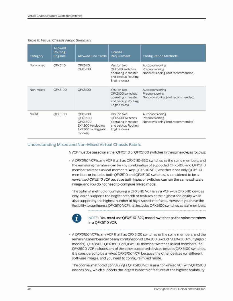
Table 6: Virtual Chassis Fabric Summary
Configuration MethodsLicenseRequirementAllowed Line Cards
AllowedRoutingEnginesCategory
AutoprovisioningPreprovisioningNonprovisioning (not recommended)
Yes (on twoQFX5110 switchesoperating in masterand backup RoutingEngine roles)
QFX5110QFX5100
QFX5110Non-mixed
AutoprovisioningPreprovisioningNonprovisioning (not recommended)
Yes (on twoQFX5100 switchesoperating in masterand backup RoutingEngine roles)
QFX5100QFX5100Non-mixed
AutoprovisioningPreprovisioningNonprovisioning (not recommended)
Yes (on twoQFX5100 switchesoperating in masterand backup RoutingEngine roles)
QFX5100QFX3600QFX3500EX4300 (excludingEX4300multigigabitmodels)
QFX5100Mixed
UnderstandingMixed and Non-Mixed Virtual Chassis Fabric
AVCFmustbebasedoneitherQFX5110orQFX5100switches in the spine role, as follows:
• AQFX5110 VCF is any VCF that has QFX5110-32Q switches as the spinemembers, and
the remainingmembers can be any combination of supported QFX5100 andQFX5110
member switches as leaf members. Any QFX5110 VCF, whether it has only QFX5110
members or includes both QFX5110 and QFX5100 switches, is considered to be a
non-mixed QFX5110 VCF because both types of switches can run the same software
image, and you do not need to configure mixedmode.
The optimal method of configuring a QFX5110 VCF is as a VCF with QFX5110 devices
only, which supports the largest breadth of features at the highest scalability while
also supporting the highest number of high-speed interfaces. However, you have the
flexibility to configureaQFX5110VCF that includesQFX5100switchesas leafmembers.
NOTE: Youmust useQFX5110-32Qmodel switches as the spinemembersin a QFX5110 VCF.
• AQFX5100 VCF is any VCF that has QFX5100 switches as the spinemembers, and the
remainingmemberscanbeanycombinationofEX4300(excludingEX4300multigigabit
models), QFX3500, QFX3600, or QFX5100member switches as leaf members. If a
QFX5100VCF includes any of the other supported devices besidesQFX5100 switches,
it is considered to be amixed QFX5100 VCF, because the other devices run different
software images, and you need to configure mixedmode.
TheoptimalmethodofconfiguringaQFX5100VCF isasanon-mixedVCFwithQFX5100
devices only, which supports the largest breadth of features at the highest scalability
Copyright © 2018, Juniper Networks, Inc.48
Virtual Chassis Feature Guide for Switches
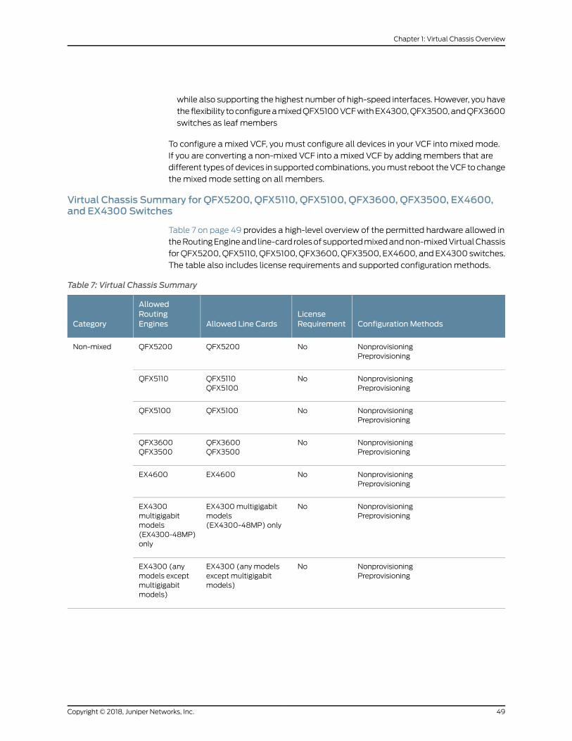
while also supporting the highest number of high-speed interfaces. However, you have
the flexibility toconfigureamixedQFX5100VCFwithEX4300,QFX3500,andQFX3600
switches as leaf members
To configure a mixed VCF, youmust configure all devices in your VCF into mixedmode.
If you are converting a non-mixed VCF into amixed VCF by adding members that are
different typesof devices in supportedcombinations, youmust reboot theVCF tochange
themixedmode setting on all members.
Virtual Chassis Summary for QFX5200, QFX5110, QFX5100, QFX3600, QFX3500, EX4600,and EX4300 Switches
Table 7 on page 49 provides a high-level overview of the permitted hardware allowed in
theRoutingEngineand line-card rolesof supportedmixedandnon-mixedVirtualChassis
forQFX5200,QFX5110, QFX5100,QFX3600,QFX3500, EX4600, and EX4300 switches.
The table also includes license requirements and supported configuration methods.
Table 7: Virtual Chassis Summary
Configuration MethodsLicenseRequirementAllowed Line Cards
AllowedRoutingEnginesCategory
NonprovisioningPreprovisioning
NoQFX5200QFX5200Non-mixed
NonprovisioningPreprovisioning
NoQFX5110QFX5100
QFX5110
NonprovisioningPreprovisioning
NoQFX5100QFX5100
NonprovisioningPreprovisioning
NoQFX3600QFX3500
QFX3600QFX3500
NonprovisioningPreprovisioning
NoEX4600EX4600
NonprovisioningPreprovisioning
NoEX4300multigigabitmodels(EX4300-48MP) only
EX4300multigigabitmodels(EX4300-48MP)only
NonprovisioningPreprovisioning
NoEX4300 (any modelsexcept multigigabitmodels)
EX4300 (anymodels exceptmultigigabitmodels)
49Copyright © 2018, Juniper Networks, Inc.
Chapter 1: Virtual Chassis Overview

Table 7: Virtual Chassis Summary (continued)
Configuration MethodsLicenseRequirementAllowed Line Cards
AllowedRoutingEnginesCategory
NonprovisioningPreprovisioning
NoQFX5100QFX3600QFX3500EX4300 (any modelsexcept multigigabitmodels)
QFX5100Mixed
NonprovisioningPreprovisioning
NoQFX3600QFX3500EX4300 (any modelsexcept multigigabitmodels)
QFX3600QFX3500
NonprovisioningPreprovisioning
NoEX4600EX4300 (any modelsexcept multigigabitmodels)
EX4600
NonprovisioningPreprovisioning
NoEX4300 (any modelsincluding multigigabitmodels)
EX4300multigigabitmodels(EX4300-48MP)
Understanding the Routing Engine Role in a Virtual ChassisWith Different Types of Switches
When you have different types of switches in a Virtual Chassis, the combination of
switches you are interconnecting determines which switches should be in the master
Routing Engine role. We also recommend always configuring the same type of switch
into the master and backup Routing Engine roles, to ensure that the switch operating as
the master remains the same type of switch in the event of a switchover.
• In a Virtual Chassis with QFX5110 and QFX5100 switches, which is considered to be a
non-mixed QFX5110 Virtual Chassis, we recommend using QFX5110 switches in the
masterorbackupRoutingEngine roles, andyoucanuseQFX5110or supportedQFX5100
switches for the remaining members in line-card role.
• InamixedVirtualChassiswithQFX5100switchescombinedwithQFX3600,QFX3500,
or EX4300 switches, you should use QFX5100 switches in the master Routing Engine
role, and you can use QFX5100, QFX3600, QFX3500, or EX4300 switches in the
line-card role.
• In amixedVirtualChassiswithQFX3600orQFX3500switcheswithEX4300switches,
you should use QFX3500 or QFX3600 switches in the Routing Engine role, and you
can use QFX3600, QFX3500, or EX4300 switches in the line-card role.
• In a mixed EX4300 and EX4600 Virtual Chassis, EX4600 switches automatically
assume themaster and backup Routing Engine roles, and you can use EX4300 or
Copyright © 2018, Juniper Networks, Inc.50
Virtual Chassis Feature Guide for Switches

EX4600 switches in the line-card role. (EX4600 switches can be in a mixed Virtual
Chassis with any EX4300model switches except multigigabit models.)
• In amixed EX4300Virtual Chassis with EX4300multigigabitmodel (EX4300-48MP)
switchesandanyothermodelsofEX4300switches, youmustuseEX4300multigigabit
models in theRoutingEngine role, andyoucanuseanyEX4300switches in the line-card
role.
InmostmixedVirtual Chassis, youmust configure your Virtual Chassis to ensure a switch
that supports operating as amaster Routing Engine assumes themaster Routing Engine
role.Without user configuration, any switchmight assume themaster or backup Routing
Engine role, with the exception of EX4300 switches in an EX4600 or QFX Series Virtual
Chassis or VCF, which can never assume the Routing Engine role.
Understanding QFX5100 andQFX5110 Switches in a Virtual Chassis
Up to ten QFX5100 and QFX5110 switches can be interconnected using Virtual Chassis
ports (VCPs) to form aQFX5110 Virtual Chassis, which is considered to be a non-mixed
Virtual Chassis because both types of switches can run the same software image, and
youdonotneed toconfiguremixedmode.AQFX5110VirtualChassis cancontainQFX5110
and supported QFX5100 switches in any combination, but we recommend that only
QFX5110 switches be in the master and backup Routing Engine roles, and QFX5100
switches only be configured into line-card role.
QFX5100switchescanalsobe interconnected intoamixedVirtualChassiswithQFX3500,
QFX3600, and EX4300 switches. See the next section for more information on amixed
QFX5100 Virtual Chassis.
UnderstandingEX4300,QFX3500,QFX3600,andQFX5100Switches inaMixedVirtualChassis
Acombinationofup to tenEX4300(excludingmultigigabitmodels),QFX3500,QFX3600,
and QFX5100 switches can be interconnected using VCPs to form amixed QFX Series
Virtual Chassis.
In a mixed QFX Series Virtual Chassis that includes QFX5100 switches, only QFX5100
switches should be configured into the Routing Engine role, and the remainingmembers
canbeanycombinationofEX4300,QFX3500,QFX3600,orQFX5100switchesconfigured
into line-card role.
QFX3500 and QFX3600 switches can be interconnected using VCPs to form a Virtual
Chassis that is non-mixed; you donot need to configuremixedmode for aVirtual Chassis
composed of only QFX3500 andQFX3600 switches. QFX3500 andQFX3600 switches
can also be in a mixed QFX Series Virtual Chassis with EX4300 switches. In this
combination, onlyQFX3500orQFX3600switches shouldbeconfigured into theRouting
Engine role, and the remainingmemberscanbeQFX3500,QFX3600,orEX4300switches
configured into line-card role.
EX4300 switches (excluding multigigabit models) can also be interconnected into a
mixed Virtual Chassis with EX4600 switches. See the next section for information on
mixed EX4300 and EX4600 Virtual Chassis.
51Copyright © 2018, Juniper Networks, Inc.
Chapter 1: Virtual Chassis Overview

UnderstandingMixed EX4300 and EX4600 Virtual Chassis
Any EX4300 switches (except for multigigabit models) and EX4600 switches can be
interconnected into a Virtual Chassis.
In a mixed EX4300 and EX4600 Virtual Chassis:
• You can interconnect up to tenmember switches.
• An EX4600 switch automatically assumes themaster Routing Engine role.
• EX4300 switches cannot assume the Routing Engine role.
EX4600 switches cannot be in a mixed Virtual Chassis with any other type of switch
besides EX4300 switches that are not multigigabit model switches.
Understanding EX4300Multigigabit and Other EX4300Model Switches in aMixed EX4300Virtual Chassis
You can combine EX4300multigigabit model (EX4300-48MP) switches with other
EX4300 switches into amixed EX4300 Virtual Chassis.
NOTE: If an EX4300 Virtual Chassis has only EX4300multigigabit modelswitches, or only a combination of other models of EX4300 switches, theVirtual Chassis is a non-mixed Virtual Chassis and should not be configuredintomixedmode.
In a mixed EX4300 Virtual Chassis:
• You can interconnect up to tenmember switches.
• EX4300 switches in the Virtual Chassis that are notmultigigabitmodel switchesmust
beconfiguredwith the ieee-clause-82optionwhensettingmixedmode.See“Configuring
an EX2300, EX3400, or EX4300 Virtual Chassis” on page 69 for details.
• Only EX4300multigigabit model switches can be in the Routing Engine role.
• EX4300 switches that are not multigigabit model switches must be configured into
line-card role.
EX4300multigigabit switches cannot be in a mixed Virtual Chassis with any other type
of switch besides other EX4300 switches.
Understanding EX4200, EX4500, and EX4550 Switches in aMixed Virtual Chassis
EX4200 switches, EX4500 switches, and EX4550 switches can be interconnected into
a Virtual Chassis to form amixed EX4200 and EX4500 Virtual Chassis, mixed EX4200
and EX4550 Virtual Chassis, mixed EX4500 and EX4550 Virtual Chassis, or mixed
EX4200, EX4500, and EX4550 Virtual Chassis. Themixed Virtual Chassis supports up
to 10member switches regardlessofwhether theswitchesareEX4200switches, EX4500
switches, or EX4550 switches. Any model of EX4200, EX4500, or EX4550 switch can
be interconnected into the samemixedVirtual Chassis. Themaster election process that
Copyright © 2018, Juniper Networks, Inc.52
Virtual Chassis Feature Guide for Switches

decidesmember switch roles in amixedVirtual Chassis is identical to themaster election
process in a non-mixed Virtual Chassis, so anymember switch in amixed Virtual Chassis
can assume themaster, backup, or line-card role.
EX4200 switches, EX4500 switches, and EX4550 switches cannot be interconnected
into a Virtual Chassis with any other switches.
RelatedDocumentation
Virtual Chassis Fabric Overview•
• Understanding QFX Series Virtual Chassis on page 29
• Understanding Virtual Chassis Fabric Components
• Understanding Virtual Chassis Components on page 34
Understanding How theMaster in a Virtual Chassis Is Elected
NOTE: This topic does not apply to EX8200 Virtual Chassis.
All switches that are interconnected in a Virtual Chassis configuration are member
switches of thatVirtual Chassis. EachVirtual Chassis configuration has onemember that
functions as themaster in a Routing Engine role and controls the Virtual Chassis
configuration.
WhenaVirtualChassis configurationboots, the JuniperNetworks Junosoperating system
(JunosOS) on the switches automatically runs amaster election algorithm to determine
which member switch assumes the role of master.
The algorithm proceeds from the top condition downward until the stated condition is
satisfied:
1. Choose themember with the highest user-configuredmastership priority (255 is the
highest possible value). A switch with amastership priority of 0 will always stay in
the linecard role.
2. Choose themember that wasmaster the last time the Virtual Chassis configuration
booted.
3. Choose themember that has been included in the Virtual Chassis configuration for
the longest period of time. (For this to be a deciding factor, there has to be aminimum
time lapseof 1minutebetweenthepower-onsof the individual interconnectedmember
switches.)
4. Choose themember with the lowest MAC address.
The variations among switches and switch models do not impact the master election
algorithm.
53Copyright © 2018, Juniper Networks, Inc.
Chapter 1: Virtual Chassis Overview

To ensure that a specific member is elected as the master:
1. Power on only the switch that you want to configure as master of the Virtual Chassis
configuration.
2. Configure the mastership priority of that member to have the highest possible value
(255).
3. Continue to configure other members through themaster member.
4. Power on the other members.
You can also specify the switch roles by preprovisioning your Virtual Chassis.
Preprovisioning a Virtual Chassis allows you to manually assign the member ID and role
for each switch in the Virtual Chassis. See Configuring an EX3300 Virtual Chassis (CLI
Procedure), Configuring an EX4200, EX4500, or EX4550 Virtual Chassis (CLI Procedure),
“ConfiguringanEX2300,EX3400,orEX4300VirtualChassis”onpage69,or “Configuring
a QFX Series Virtual Chassis (CLI Procedure)” on page 84.
RelatedDocumentation
EX Series Virtual Chassis Overview on page 19•
• Understanding QFX Series Virtual Chassis on page 29
• Understanding Virtual Chassis Components on page 34
• Understanding EX Series Virtual Chassis Configuration on page 59
Understanding Global Management of a Virtual Chassis
NOTE: This topic does not apply to EX8200 Virtual Chassis. SeeUnderstanding Global Management of an EX8200 Virtual Chassis.
AVirtualChassis is composedofmultiple switches, and it, therefore, hasmultiple console
ports andmultiple out-of-bandmanagement Ethernet ports located on the switches.
You can connect a PC or laptop directly to a console port of any member switch to set
upandconfigure theVirtualChassis.Whenyouconnect to theconsoleportofanymember
switch, the console session is redirected to the master switch, as shown in
Figure 1 on page 55.
Copyright © 2018, Juniper Networks, Inc.54
Virtual Chassis Feature Guide for Switches
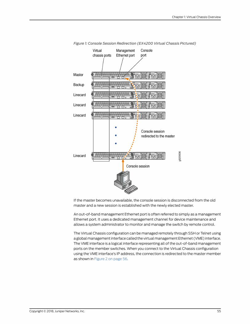
Figure 1: Console Session Redirection (EX4200 Virtual Chassis Pictured)
If the master becomes unavailable, the console session is disconnected from the old
master and a new session is established with the newly electedmaster.
An out-of-bandmanagement Ethernet port is often referred to simply as amanagement
Ethernet port. It uses a dedicatedmanagement channel for device maintenance and
allows a system administrator to monitor andmanage the switch by remote control.
The Virtual Chassis configuration can bemanaged remotely through SSHor Telnet using
aglobalmanagement interfacecalled thevirtualmanagementEthernet (VME) interface.
The VME interface is a logical interface representing all of the out-of-bandmanagement
ports on themember switches. When you connect to the Virtual Chassis configuration
using the VME interface’s IP address, the connection is redirected to themastermember
as shown in Figure 2 on page 56.
55Copyright © 2018, Juniper Networks, Inc.
Chapter 1: Virtual Chassis Overview

Figure 2: Management Ethernet Port Redirection to the VME Interface
If themaster management Ethernet link is unavailable, the session is redirected through
the backupmanagement Ethernet link. If there is no active management Ethernet link
on the backup, the VME interface chooses amanagement Ethernet link on one of the
linecard members, selecting the linecard member with the lowest member ID as its first
choice.
You can configure an IP address for the VME global management interface at any time.
You can perform remote configuration and administration of all members of the Virtual
Chassis configuration through the VME interface.
RelatedDocumentation
Understanding Virtual Chassis Components on page 34•
• Example: Configuring an EX4200 Virtual Chassis with a Master and Backup in a Single
Wiring Closet
Copyright © 2018, Juniper Networks, Inc.56
Virtual Chassis Feature Guide for Switches

• Configuring the Virtual Management Ethernet Interface for Global Management of an EX
Series Virtual Chassis (CLI Procedure)
Understanding Nonvolatile Storage in a Virtual Chassis
NOTE: This topic applies to all EX Series Virtual Chassis except EX8200Virtual Chassis.
The EXSeries or QFXSeries switches store the Juniper Networks Junos operating system
(Junos OS) system files in internal flash memory. In the Virtual Chassis configurations,
both the master and the backup switch store the configuration information for all the
member switches.
• Nonvolatile Memory Features on page 57
Nonvolatile Memory Features
Junos OS optimizes the way the Virtual Chassis stores its configuration if a member
switch or the Virtual Chassis configuration is shut down improperly:
• If the master is not available, the backup switch takes on the role of the master and
its internal flashmemory takesover as thealternate location formaintainingnonvolatile
configuration memory.
• If a member switch is taken offline for repair, the master stores the configuration of
the member switch.
RelatedDocumentation
Understanding QFX Series Virtual Chassis on page 29•
• Command Forwarding Usage with an EX Series Virtual Chassis on page 119
Understanding Virtual Chassis Port Link Aggregation
NOTE: This topic applies to all EX Series and QFX Series Virtual Chassis,except for EX8200 Virtual Chassis. SeeUnderstanding Virtual Chassis PortLink Aggregation in an EX8200Virtual Chassis for information about EX8200Virtual Chassis link aggregation.
Within a Virtual Chassis, you can combine physical Ethernet ports to form a logical
point-to-point link knownas a link aggregation group (LAG) or bundle. The interfaces that
are included in a LAG are sometimes referred to as member interfaces. Do not confuse
this termwith member switches, which refers to switches that are interconnected into
a Virtual Chassis. A LAG in a Virtual Chassis can be composed of member interfaces
located in different member switches in the Virtual Chassis, or composed of multiple
57Copyright © 2018, Juniper Networks, Inc.
Chapter 1: Virtual Chassis Overview

redundant Virtual Chassis Port (VCP) links between twomember switches in the Virtual
Chassis, as described in the following sections.
• Virtual Chassis Network Interface LAG Among Virtual Chassis Members on page 58
• Virtual Chassis Port LAG Between Two Virtual Chassis Members on page 58
Virtual Chassis Network Interface LAG Among Virtual Chassis Members
When setting up interfaces in a Virtual Chassis, you can configure a combination of
physical Ethernet ports belonging to different member switches to form a LAG. A LAG
provides more bandwidth than a single Ethernet link can provide. Additionally, link
aggregation provides network redundancy by load-balancing traffic across all available
links. If one of the links fails, the system automatically load-balances traffic across all
remaining links.
Similarly, if aVirtual Chassismember switch that has LAGmember interfaces onmultiple
member switches fails for any reason, the traffic traversing the LAG can be redirected
through the activemember switch. This setup has benefits for failover purposes and can
be especially beneficial in cases when amember switch needs to be inactive for some
time, such as during a software upgrade using NSSU.
Virtual Chassis Port LAG Between Two Virtual Chassis Members
You can configure optical uplink ports into Virtual Chassis ports (VCPs) that connect EX
Series or QFX series switches together to form a Virtual Chassis. When you configure
multiple uplink port VCPs connecting the same twomember switches, those ports
automatically form a LAG if the ports are configured to operate at the same link speeds.
Each LAG is assigned a positive-integer identifier called a trunk ID. Up to 8 redundant
VCP links can form a VCP LAG connecting twomembers in a Virtual Chassis, depending
on the number of available ports that can be VCPs.
OnEX2200andEX2200-Cswitches, youcanalsoconfigure theRJ-45 interfaces, including
built-in network ports with 10/100/1000BASE-T Gigabit Ethernet connectors and
1000BASE-T RJ-45 transceivers, into VCPs. Any interfaces on these switches that are
configured as VCPs interconnecting twomembers will automatically form a LAG,
regardless of whether the interfaces are optical transceiver interfaces, RJ-45 transceiver
interfaces,orbuilt-innetworkportswith 10/100/1000BASE-TGigabitEthernetconnectors.
A VCP LAG automatically forms when any twomember switches are interconnected
with two or more VCP links of the same link speed in any of these configurations:
• If the VCP ports on both switches are ports you configured into VCPs or
default-configured VCPs (for switches that have default VCPs).
• If theVCPportsonboth switchesarededicatedVCPs (for switches thathavededicated
VCPs).
• In amixedVirtualChassiswhen theVCP links interconnect twodifferent switchmodels.
A LAGover uplink VCPs provides higher overall bandwidth for forwarding traffic between
themember switches connected by the optical VCPs, faster management
Copyright © 2018, Juniper Networks, Inc.58
Virtual Chassis Feature Guide for Switches

communications, andgreater redundancyofoperationsamongthemembers thanwould
be available without the LAG.
See “Setting an Uplink Port on an EX Series or QFX Series Switch as a Virtual Chassis
Port”onpage 108or “ConfiguringaQFXSeriesVirtualChassis (CLIProcedure)”onpage84
for information about configuring uplink ports into VCPs.
RelatedDocumentation
EX Series Virtual Chassis Overview on page 19•
• Understanding Aggregated Ethernet Interfaces and LACP
• Example: Configuring Aggregated Ethernet High-Speed Uplinks Between an EX4200
Virtual Chassis Access Switch and an EX4200 Virtual Chassis Distribution Switch
• Example: Configuring Aggregated Ethernet High-Speed Uplinks with LACP Between an
EX4200VirtualChassisAccessSwitchandanEX4200VirtualChassisDistributionSwitch
• Example: Configuring an EX4200 Virtual Chassis Interconnected Across Multiple Wiring
Closets
• Example:ConnectingEX4500MemberSwitches inaVirtualChassisAcrossWiringClosets
• Example: Configuring LinkAggregationGroupsUsingEX4200UplinkVirtualChassisPorts
• Understanding QFX Series Virtual Chassis on page 29
• Configuring a QFX Series Virtual Chassis (CLI Procedure) on page 84
Understanding EX Series Virtual Chassis Configuration
NOTE: This topic applies to all EX Series Virtual Chassis except EX8200Virtual Chassis. SeeUnderstanding EX8200 Virtual Chassis Components forinformation about EX8200 Virtual Chassis.
Youconfigureandmanagealmostall aspectsofanEXSeriesVirtualChassis configuration
through themaster switch of the Virtual Chassis. However, you can also configure Virtual
Chassis parameters when a switch is a standalone switch not interconnectedwith other
members.
• Standalone Switch Virtual Chassis Characteristics on page 59
• Interconnecting Virtual Chassis Members with Virtual Chassis Ports on page 60
• Virtual Chassis Provisioning on page 60
Standalone Switch Virtual Chassis Characteristics
EX Series switches that support Virtual Chassis have some innate characteristics of a
VirtualChassisbydefault.Astandaloneswitch isassignedmember ID0and is themaster
of itself. Therefore, you can edit its Virtual Chassis configuration.
When the standalone switch is interconnected with an existing Virtual Chassis
configuration, theVirtualChassis configuration statementsandanyuplinkVirtualChassis
59Copyright © 2018, Juniper Networks, Inc.
Chapter 1: Virtual Chassis Overview

port (VCP) settings that you previously specified on the standalone switch remain part
of its configuration.
Interconnecting Virtual Chassis Members with Virtual Chassis Ports
A switch is not recognized by the Virtual Chassis as amember switch until it is
interconnectedwith themaster or interconnectedwith an existingmember of theVirtual
Chassis using Virtual Chassis ports (VCPs). Some switches have dedicated VCPs that
cannot be used for any other purpose. Other switches have ports that are configured into
VCPswith the default factory settings. You can usually reconfigure those ports to remove
theVCP settings and subsequently use themas network ports instead. Switcheswithout
dedicated or default-configured VCPs have supported network or uplink ports that can
be configured into VCPs. See “Virtual Chassis Port Options” on page 38 for a summary
of the VCP options on switches that can be in a Virtual Chassis.
EX4200, EX4500, and EX4550 switches have dedicated VCPs, but when one of these
switches is located too far away to be interconnected through dedicated VCPs, you can
configure a network or uplink port as a VCP. On EX4300multigigabit model
(EX4300-48MP)switches, the four40-GbpsQSFP+portson the rearpanelarededicated
VCPs, and no other ports on those switches can be used as VCPs. EX2200, EX2300
(including multigigabit models), EX3300, EX3400, and EX4300 switches (excluding
multigigabitmodels) do not have dedicated VCPs. On these switches, you form aVirtual
Chassis using network or uplink ports configured intoVCPs to interconnect themembers.
Uplink ports 2 and 3 on EX3300 switches are configured by default as VCPs. You can
change this default configuration or configure any of the other uplink ports as VCPs.
QSFP+ uplink ports on EX3400 switches and any QSFP+ ports on EX4300 switches are
also configured by default as VCPs. Other EX Series switches do not have any ports
configured as VCPs by default, so youmust configure supported network or uplink ports
into VCPs to form a Virtual Chassis.
When a port is set as a VCP, it cannot be used for any other purpose. If you want to use
theport for another purpose, youmustdelete theVCPsetting. Youcan run this command
directly on themember whose uplink VCP setting you want to delete or through the
master member of the Virtual Chassis configuration.
CAUTION: Deleting a VCP in a Virtual Chassis configuration can cause theVirtual Chassis configuration to split. For more information, see“Understanding Split andMerge in a Virtual Chassis” on page 61.
AVCP link aggregation group (LAG)will be formedautomaticallywhen the newmember
switch is added to the configuration if more than one such link with the same speed is
detected among the VCPs on the newmember and an existing member. See
“Understanding Virtual Chassis Port Link Aggregation” on page 57.
Virtual Chassis Provisioning
You can create a preprovisioned configuration. This type of configuration allows you to
deterministically control the member ID and role assigned to amember switch by
associating the switch with its serial number. For an example of a preprovisioned
Copyright © 2018, Juniper Networks, Inc.60
Virtual Chassis Feature Guide for Switches

configuration, see Example: Configuring an EX4200Virtual Chassis Using a Preprovisioned
Configuration File. When adding a switch to a preprovisioned Virtual Chassis, youmight
be able to simplify the procedure by using the autoprovisioning feature, which
automatically converts the interconnecting inks into VCPs when cabling the new switch
into the Virtual Chassis.
If a switch is interconnected with other switches in a Virtual Chassis configuration, each
individual switch that is included as amember of the configuration is identified with a
member ID. Themember ID functions as an FPC slot number. When you are configuring
interfaces for a Virtual Chassis configuration, you specify the appropriate member ID as
the slot element of the interface name.
Thedefault factory settings for aVirtualChassis configuration includeFPC0asamember
of the default VLANbecause FPC0 is configured as part of the ethernet-switching family.
To include the FPC in the default VLAN, add the ethernet-switching family to the
configurations for those interfaces.
RelatedDocumentation
Understanding Virtual Chassis Components on page 34•
• Understanding How the Master in a Virtual Chassis Is Elected on page 53
• Configuring an EX3300 Virtual Chassis (CLI Procedure)
• Configuring an EX4200, EX4500, or EX4550 Virtual Chassis (CLI Procedure)
• Configuring an EX2300, EX3400, or EX4300 Virtual Chassis on page 69
Understanding Split andMerge in a Virtual Chassis
In a Virtual Chassis, two or more switches are connected together to form a unit that is
managed as a single chassis. If there is a disruption to the Virtual Chassis configuration
due to member switches failing or being removed from the configuration, the Virtual
Chassis configuration splits into two separate Virtual Chassis. This situation could cause
disruptions in the network if the two separate configurations share common resources,
such as global IP addresses. The split andmerge feature provides amethod to prevent
the separate Virtual Chassis configurations from adversely affecting the network and
also allows the two parts to merge back into a single Virtual Chassis configuration.
NOTE: If a Virtual Chassis configuration splits into separate parts, werecommend that you resolve the problem that caused the Virtual Chassisconfiguration to split as soon as possible.
You can also use this feature to merge two active but separate Virtual Chassis that have
not previously beenpart of the sameconfiguration into oneVirtual Chassis configuration.
NOTE: The split andmerge feature is enabled by default on EX Series andQFX Series Virtual Chassis. You can disable the split andmerge feature byusing the set virtual-chassis no-split-detection command.
61Copyright © 2018, Juniper Networks, Inc.
Chapter 1: Virtual Chassis Overview

This topic describes:
• What HappensWhen a Virtual Chassis Configuration Splits on page 62
• Merging Virtual Chassis Configurations on page 63
What HappensWhen a Virtual Chassis Configuration Splits
When a Virtual Chassis configuration splits into two separate Virtual Chassis
configurations, the individual member switches detect this topology change and run the
master election algorithm to select a newmaster for each of the two Virtual Chassis
configurations. The newmasters then determine whether their Virtual Chassis
configuration remains active. One of the configurations remains active based on the
following:
• It contains both the stable master and the stable backup (that is, the master and
backup from the original Virtual Chassis configuration before the split).
• It contains the stable master and the configuration is greater than half the Virtual
Chassis size.
• It contains the stable backup and is at least half the Virtual Chassis size.
In accordancewith the rules given in the second and third list items, if the Virtual Chassis
configuration splits into two equal parts and the stable master and stable backup are in
different parts, then the part that contains the stable backup becomes active.
NOTE: Thenumber ofmembers in theVirtual Chassis configuration includesall member switches connected to dateminus the number whose VirtualChassis member IDs have been recycled (that is, made available forreassignment). Therefore, the size of the Virtual Chassis configurationincreases when a newmember switch is detected and decreases when amember switch's ID is recycled.
These rules ensure that only one of the two separate Virtual Chassis configurations
created by the split remains active. Themember switches in the inactive Virtual Chassis
configuration remain in a linecard role. For the inactivemembers to becomeactive again,
one of the following things must happen:
• The problem that caused the original Virtual Chassis configuration to split is resolved,
allowing the two Virtual Chassis configurations to merge.
• You load the factory default configuration on the inactive members, which causes the
inactive members to function as standalone switches or become part of a different
Virtual Chassis configuration.
NOTE: When you remove amember switch from a Virtual Chassisconfiguration, we recommend that you recycle themember ID using therequest virtual-chassis recycle command.
Copyright © 2018, Juniper Networks, Inc.62
Virtual Chassis Feature Guide for Switches

Merging Virtual Chassis Configurations
There are two scenarios in which separate Virtual Chassis merge:
• AVirtual Chassis configuration that had split into two is nowmerging back into a single
configuration because the problem that had caused it to split has been resolved.
• Youwant tomerge twoVirtualChassis thathadnotpreviouslybeenconfigured together.
Every Virtual Chassis configuration has a unique ID (VCID) that is automatically assigned
when the Virtual Chassis configuration is formed. You can also explicitly assign a VCID
using the set virtual-chassis id command. A VCID that you assign takes precedence over
automatically assigned VCIDs.
When you reconnect the separate Virtual Chassis configurations or connect them for the
first time, the members determine whether or not the separate Virtual Chassis
configurations canmerge. Themembers use the following rules to determine whether
a merge is possible:
• If the Virtual Chassis configurations have the same VCID, then the configurations can
merge. If the two Virtual Chassis were formed as the result of a split, they have the
same VCID.
• If the VCIDs are different, then the two configurations canmerge only if both are active
(inactive configurations cannot merge, ensuring that members removed from one
Virtual Chassis configuration do not becomemembers of another Virtual Chassis
configuration). If the configurations to merge are both active and one of them has a
user-configured VCID, this ID becomes the ID of the merged Virtual Chassis. If neither
Virtual Chassis has a user-configured VCID, then the VCID of the configuration with
the highest mastership priority becomes the ID of the merged Virtual Chassis. The
resulting merged Virtual Chassis configuration is active.
When you connect two Virtual Chassis configurations, the following events occur:
1. Connecting the twosplit Virtual Chassis configurations triggers the shortest-path-first
(SPF)algorithm.TheSPFalgorithmcomputes thenetwork topologyand then triggers
the master election algorithm. Themaster election algorithmwaits for the members
to synchronize the topology information before running.
2. Themaster election algorithmmerges the VCIDs of all the members.
3. Eachmember runs the master election algorithm to select a master and a backup
from among all members with the same VCIDs. For more information, see
“Understanding How the Master in a Virtual Chassis Is Elected” on page 53.
4. Themaster determineswhether the Virtual Chassis configuration is active or inactive.
(See “What HappensWhen a Virtual Chassis Configuration Splits” on page 62.)
63Copyright © 2018, Juniper Networks, Inc.
Chapter 1: Virtual Chassis Overview

5. If the Virtual Chassis configuration is active, the master assigns roles to all members.
If the Virtual Chassis configuration is inactive, the master assigns all members the
role of linecard.
6. When the other members receive their role from themaster, they change their role to
backup or linecard. They also use the active or inactive state information sent by the
master to set their own state to active or inactive and to construct the Virtual Chassis
member list from the information sent by the master.
7. If theVirtual Chassis state is active, themasterwaits formessages from themembers
indicating that theyhavechanged their roles to theassigned roles, and then themaster
changes its own role to master.
NOTE: When youmerge two Virtual Chassis that had not previously beenpart of the same Virtual Chassis configuration, any configuration settings(such as the settings for Telnet and FTP services, graceful Routing Engineswitchover (GRES), fast failover, VLANs, and so on) that exist on the newmaster become the configuration settings for allmembers of the newVirtualChassis, overwriting any other configuration settings.
RelatedDocumentation
Disabling Split and Merge in a Virtual Chassis (CLI Procedure) on page 114•
• Assigning the Virtual Chassis ID to Determine Precedence During a Virtual Chassis
Merge (CLI Procedure) on page 117
• Example: Assigning the Virtual Chassis ID to Determine Precedence During an EX4200
Virtual Chassis Merge
• Understanding EX Series Virtual Chassis Configuration on page 59
• Understanding QFX Series Virtual Chassis on page 29
Understanding Automatic Software Update on Virtual Chassis Member Switches
You can use the automatic software update feature to automatically update the Juniper
Networks Junos operating system (Junos OS) version on prospective member switches
as you add them to an EX Series or QFX Series Virtual Chassis.
This topic includes:
• Automatic Software Update Basics on page 64
• Automatic Software Update Restrictions on page 65
Automatic Software Update Basics
When you have configured automatic software update on a Virtual Chassis, the Junos
OS version is updated on the newmember switchwhen you add it to the Virtual Chassis.
Copyright © 2018, Juniper Networks, Inc.64
Virtual Chassis Feature Guide for Switches

The newmember switch immediately joins the Virtual Chassis configuration and is put
in the active state.
For a standalone switch to join an existing Virtual Chassis, it must be running the same
version of Junos OS that is running on the Virtual Chassis master. When themaster in a
Virtual Chassis detects that a new switch has been added to the configuration, it checks
the software version on the new switch. If the software version on the new switch is not
the same as the version running on themaster, the master keeps the new switch in the
inactive state. If you have not enabled the automatic software update feature, you have
to manually install the correct software version on each prospective member switch as
it is added to the Virtual Chassis.
Automatic Software Update Restrictions
Refer to Feature Explorer to see the EXSeries andQFXSeries Virtual Chassis that support
automatic software updates, and the Junos OS release versions where the feature was
introducedoneachplatform.Where theautomatic softwareupdate feature is supported,
see the Junos OS Release Notes for the release version running on themaster for any
limitations in using automatic software updates between that release version and any
prospective member switch release versions.
CAUTION: AQFX5100 switch running a Junos OS software image with“-qfx-5-” in the package filenamemust first be upgraded to a Junos OSsoftware image with “-qfx-5e-” in the package filename before it can beadded to a QFX5110 Virtual Chassis or VCF. The automatic software updateprocesscannotupdateaswitch froma“-qfx-5-” image toa“-qfx-5e-” image.See “Upgrading a QFX5100 Switch with a USB Device to Join a QFX5110Virtual Chassis or Virtual Chassis Fabric” on page 135.
After a QFX5100 switch is installed with a “-qfx-5e-” Junos OS softwareimage, the automatic software update process can successfully update theswitch automatically with a different version of a “-qfx-5e-” JunosOS imagetomatch the other members in the Virtual Chassis or VCF.
RelatedDocumentation
Understanding Software Upgrades in a Virtual Chassis on page 133•
• Configuring Automatic Software Update on Virtual Chassis Member Switches (CLI
Procedure) on page 114
• Example: Configuring Automatic Software Update on EX4200 Virtual Chassis Member
Switches
UnderstandingMACAddress Assignment on a Virtual Chassis
In a Virtual Chassis, multiple switches—each with its own set of interfaces with unique
MAC addresses—are connected together to form one chassis that can bemanaged as
asingle switch. TheMACaddressassigned toeachnetwork-facing interfaceon the switch
changeswhen the switch joins a Virtual Chassis. Because all Layer 2 traffic decisions are
65Copyright © 2018, Juniper Networks, Inc.
Chapter 1: Virtual Chassis Overview

based on an interface’s MAC address, understanding MAC address assignment is
important to understanding how network traffic is forwarded and received by the Virtual
Chassis. For additional informationabout howanetwork usesMACaddresses to forward
and receive traffic, see Understanding Bridging and VLANs on Switches.
When a Virtual Chassis is formed, the MAC address of the switch in the master role
becomes the systemMAC base address. The Virtual Chassis assigns the systemMAC
base address as the MAC address for all Layer 3 interfaces within the Virtual Chassis.
TheVirtualChassis alsoassigns thesystemMACbaseaddress to thevirtualmanagement
Ethernet (VME) interface and to all of the virtual LANs (VLANs) in the Virtual Chassis.
The systemMACbase address does not change in the event of a switchover if the switch
thatwasoriginally configured in themaster role remains amember of theVirtual Chassis.
If the switch that was originally configured in themaster role is removed from the Virtual
Chassis, the MAC address of the current member switch in the master role is assigned
as the systemMAC base address after the MAC persistence timer interval has expired.
You can configure the MAC persistence timer interval.
For Layer 2 andaggregatedEthernet interfaces, theVirtual Chassis assigns a uniqueMAC
address that is derived from themember switch MAC address to each interface. The
assignment of a unique MAC address to each network interface helps ensure that
functions that require MAC address differentiation—such as redundant trunk groups
(RTGs), LinkAggregationControlProtocol (LACP), andgeneralmonitoring functions—can
function properly.
NOTE: UniqueMACaddressassignment forLayer2andaggregatedEthernetinterfaces in a Virtual Chassis was introduced in Junos OS Release 11.3. ThesameMAC address could be assigned to interfaces on different memberswitches in the same Virtual Chassis prior to this release.
If you reconfigureaLayer 2 interface intoaLayer 3 interface, or the reverse,within aVirtual
Chassis, the MAC address of that interface changes accordingly.
MAC addresses are assigned to interfaces in a Virtual Chassis automatically—no user
configuration is possible or required. You can view the MAC addresses that are assigned
to the interfaces by using the show interfaces command.
RelatedDocumentation
Understanding MAC Address Assignment on an EX Series Switch•
• Configuring the Timer for the BackupMember to Start Using Its OwnMAC Address, as
Master of a Virtual Chassis (CLI Procedure) on page 108
• EX Series Virtual Chassis Overview on page 19
• EX8200 Virtual Chassis Overview
• Understanding QFX Series Virtual Chassis on page 29
Copyright © 2018, Juniper Networks, Inc.66
Virtual Chassis Feature Guide for Switches

Understanding High Availability on an EX Series Virtual Chassis
You increase your network’s high availability (HA) when you interconnect a Juniper
Networks EX Series Ethernet switch into a Virtual Chassis. A Virtual Chassis ismore fault
tolerant thena standaloneEXseries switchbecause it remains upwhena singlemember
switch fails, and provides sub-second convergence in the case of a device or link failure.
You can further improve HA by configuring the HA features available for your EX Series
Virtual Chassis. You can, for instance, configure Link Aggregation Groups (LAG) bundles
to includemember links onmultiple member switches in the same Virtual Chassis. This
configuration increases fault tolerancebecause traffic traversing theLAGcanbe redirected
to an active member switch when a single member switch fails.
A Virtual Chassis has dual Routing Engines—the switch in themaster role and the switch
in thebackup role—andthereforesupportsmanyHAfeaturesnotsupportedonstandalone
EX Series switches, such as Graceful Routing Engine Switchover (GRES) for hitless
failover. For information on which of the High Availability features listed in
Table 8 on page 67 are supported in your EX Series Virtual Chassis, see Feature Explorer.
Many HA features for the EX Series Virtual Chassis are designed to improve network
resiliency after a Routing Engine switchover. Table 8 on page 67 describes the effects of
a Routing Engine switchover when no high availability features are enabled and when
some High Availability features are enabled.
Table 8: Effects of a Routing Engine Switchover
Effect of Routing Engine SwitchoverHigh Availability Feature
Kernel and forwarding state information is notpreserved to the backup Routing Engine. Aconvergenceprocess that requiresall interfaceson the Virtual Chassis to be taken offline has tobeperformedbefore theVirtualChassis returnsonline. Theswitchover can take severalminutesand theVirtualChassis doesnot sendor receivetraffic until the switchover is complete.
No HA features enabled
Kernel and forwarding state information ispreserved on both Routing Engines, so theconvergence process does not occur and theswitchoverhappensquicklywithminimal trafficloss.
Graceful Routing Engine switchover (GRES)enabled
67Copyright © 2018, Juniper Networks, Inc.
Chapter 1: Virtual Chassis Overview

Table 8: Effects of a Routing Engine Switchover (continued)
Effect of Routing Engine SwitchoverHigh Availability Feature
Layer 2 protocols that are supported by NSBare not disrupted by a Routing Engineswitchover when NSB is enabled. Layer 2protocol information for all active Layer 2protocols is stored on both Routing Engineswhen NSB is enabled.
Layer 3 protocols that are supported by NSRare not disrupted by a Routing Engineswitchover when NSR is enabled. Layer 3protocol information for all active Layerprotocols is stored on both Routing Engineswhen NSR is enabled.
Nonstopactive routing(NSR),Nonstopbridging(NSB), or both enabled
Traffic is not interrupted during the switchover.Interface and kernel information is preserved.Graceful restart protocol extensions quicklycollect and restore routing information forsupported protocols from the neighboringdevices.
Graceful Protocol Restart enabled
RelatedDocumentation
• EX Series Virtual Chassis Overview on page 19
Copyright © 2018, Juniper Networks, Inc.68
Virtual Chassis Feature Guide for Switches

CHAPTER 2
Virtual Chassis Configuration
• Configuring an EX2300, EX3400, or EX4300 Virtual Chassis on page 69
• Configuring EX4600 Switches in a Mixed or Non-Mixed Virtual Chassis (CLI
Procedure) on page 79
• Configuring a QFX Series Virtual Chassis (CLI Procedure) on page 84
• Adding a New Switch to an Existing EX2300, EX3400, or EX4300 Virtual
Chassis on page 92
• Adding an EX4600 Switch to a Mixed or Non-mixed Virtual Chassis (CLI
Procedure) on page 96
• Adding a New Switch to an Existing QFX Series Virtual Chassis (CLI
Procedure) on page 98
• Replacing a Member Switch of a Virtual Chassis Configuration (CLI
Procedure) on page 101
• Configuring Mastership of a Virtual Chassis (CLI Procedure) on page 105
• Configuring the Timer for the BackupMember to Start Using Its OwnMAC Address, as
Master of a Virtual Chassis (CLI Procedure) on page 108
• Setting an Uplink Port on an EX Series or QFX Series Switch as a Virtual Chassis
Port on page 108
• Disabling Split and Merge in a Virtual Chassis (CLI Procedure) on page 114
• Configuring Automatic Software Update on Virtual Chassis Member Switches (CLI
Procedure) on page 114
• Assigning the Virtual Chassis ID to Determine Precedence During a Virtual Chassis
Merge (CLI Procedure) on page 117
• Configuring Graceful Routing Engine Switchover in a Virtual Chassis (CLI
Procedure) on page 117
Configuring an EX2300, EX3400, or EX4300 Virtual Chassis
This topic describes how to configure a non-mixedVirtual Chassis composedof EX2300,
EX3400, or EX4300 switches, or how to configure amixed EX4300 Virtual Chassis with
EX4300multigigabitmodel (EX4300-48MP)switches incombinationwithotherEX4300
model switches, as follows:
69Copyright © 2018, Juniper Networks, Inc.

• EX2300 switches cannot bemixed with any other switches in a Virtual Chassis, and
EX2300multigigabit model switches, EX2300-24MP and EX2300-48MP, can only
form a Virtual Chassis with other EX2300multigigabit model switches.
• EX3400 switches cannot bemixed with any other switches in a Virtual Chassis.
• EX4300 switches excluding multigigabit models can be configured into a non-mixed
EX4300 Virtual Chassis, and EX4300multigigabit model switches (EX4300-48MP)
can also form a non-mixed EX4300 Virtual Chassis.
In addition, EX4300multigigabitmodel switches canbe combinedwith other EX4300
model switches into amixed EX4300 Virtual Chassis with the following parameters:
• The Virtual Chassis must be configured into mixedmode.
• The EX4300 switches that are not multigigabit models must be configured with a
special port mode (ieee-clause-82) enabled on VCPs to interconnect with VCPs on
multigigabit model member switches, which is set as an option when configuring
these switches into mixedmode.
• Theswitches in theRoutingEngine rolemustbemultigigabitmodel (EX4300-48MP)
switches.
Other models of EX4300model switches excluding multigigabit models can bemixed
in supported combinations with other switches in a Virtual Chassis or Virtual Chassis
Fabric (VCF). Configuration procedures for these combinations are described in the
following other configuration topics:
• Configuring amixed Virtual Chassis that includes EX4600 and EX4300member
switches: “Configuring EX4600 Switches in aMixed or Non-Mixed Virtual Chassis (CLI
Procedure)” on page 79.
• Configuring a QFX Series Virtual Chassis that includes EX4300member switches:
“Configuring a QFX Series Virtual Chassis (CLI Procedure)” on page 84.
• Configuring EX4300 switches as leaf nodes in a VCF: Preprovisioning a Virtual Chassis
Fabric or Autoprovisioning a Virtual Chassis Fabric.
Use the following guidelines for planning the Virtual Chassis Port (VCP) connections in
this configuration procedure:
• In a non-mixed EX4300 Virtual Chassis with only EX4300multigigabit model
(EX4300-48MP) switches, interconnect the member switches using the dedicated
Virtual Chassis ports (VCPs)—the 40-Gpbs QSFP+ ports on the rear panel. These are
the only ports that can be used as VCPs on EX4300-48MP switches.
• In a mixed EX4300 Virtual Chassis with a combination of EX4300multigigabit model
switches and other EX4300model switches, youmust use 40-Gbps QSFP+ ports on
theotherEX4300model switchesasVCPsand interconnect thoseportswithdedicated
VCPs on themultigigabit model switch members.
• In an EX2300or EX3400Virtual Chassis, or an EX4300Virtual Chassis composedonly
of switches that are not multigigabit models, interconnect the member switches by
using uplink ports configured as Virtual Chassis ports (VCPs).
Copyright © 2018, Juniper Networks, Inc.70
Virtual Chassis Feature Guide for Switches

• EX2300 switches do not have any ports that are configured by default as VCPs.
• TheQSFP+ uplink ports on EX3400 and EX4300 switches, which support 40-Gbps
speeds and can connect switches that are up to 492 feet (150m) apart, are
configured as VCPs by default, so you do not need to explicitly configure them.
• On all of these switches, the SFP+ uplink ports, which support 10-Gbps speeds and
can connect switches that are up to 6.2 miles (10 km) apart, can be configured into
VCPs.
• You cannot use uplink ports installed with SFP transceivers as VCPs.
• The simplest way to interconnect EX3400 or EX4300 switches into a non-mixed
EX3400 or EX4300 Virtual Chassis is to install the switches within 492 feet of one
another and interconnect them into a Virtual Chassis by using the QSFP+ ports. For
an EX3400 or EX4300 Virtual Chassis, if the member switches must be installed in
locations that are more than 492 feet apart (such as at a different site or at a distant
locationwithin the same site), or if you are using theQSFP+ports for another purpose,
or for any EX2300 Virtual Chassis, you must configure SFP+ uplink module ports into
VCPs.
• If youneedadditionalVCPbandwidthbetweentwomemberswitches, youcanconfigure
additional ports as VCPs and create redundant links between themember switches.
RedundantVCP links are not required tobe the samespeed, but the linkswith identical
speeds automatically form a VCP link aggregation group (LAG) to provide resiliency
to the Virtual Chassis. For instance, if you have two QSFP+ ports and two SFP+ ports
configuredasVCPsconnecting the same twomember switches, themember switches
would form two LAGs—one LAGwith two40-GbpsQSFP+port links and anotherwith
two 10-Gbps SFP+ port links.
NOTE: AVirtual Chassis configuration has twoRouting Engines—themasterswitch and the backup switch. Therefore, we recommend that you alwaysuse commit synchronize rather than simply commit to save configuration
changesmade for a Virtual Chassis. This ensures that the configurationchanges are saved on both Routing Engines.
An EX2300, EX3400, or EX4300 Virtual Chassis can be configured with either of the
following two options:
• Anonprovisionedconfiguration—Themaster sequentially assignsamember ID toother
member switches. The role is determined by themastership priority value and other
factors in the master election algorithm.
• A preprovisioned configuration—You can deterministically control the member ID and
role assigned to amember switch by tying the member switch to its serial number.
All member switches must be running the same version of Junos OS to form a Virtual
Chassis.
71Copyright © 2018, Juniper Networks, Inc.
Chapter 2: Virtual Chassis Configuration

NOTE: Youmust configure a VLAN on all interfaces in the Virtual Chassis,with theexceptionof the interfacesonmemberswitch0,before the interfacescan send or receive traffic. The interfaces onmember switch 0 are initiallyplaced into the default VLAN; the interfaces on all other member switchesare not placed into any VLAN. See Configuring VLANs for EX Series Switcheswith ELS Support (CLI Procedure).
NOTE: OnanEX4300VirtualChassis,STP isdisabledonall interfacesexceptthe interfacesonmember switch0until sometypeof spanning-treeprotocolis enabled. See Configuring RSTP on EX Series Switches (CLI Procedure)(RSTP is thedefault spanning-tree protocol),ConfiguringMSTPonSwitches,or Configuring VLAN Spanning Tree Protocol on Switches to enable aspanning-tree protocol on the interfaces in your EX4300 Virtual Chassis.
This topic describes:
• Configuring an EX2300, EX3400, or EX4300 Virtual Chassis with a Nonprovisioned
Configuration File on page 72
• Configuring an EX2300, EX3400, or EX4300 Virtual Chassis with a Preprovisioned
Configuration File on page 75
ConfiguringanEX2300,EX3400,orEX4300VirtualChassiswithaNonprovisionedConfigurationFile
Youcanuseanonprovisionedconfiguration to configureanEX2300, EX3400, or EX4300
Virtual Chassis.
To configure the Virtual Chassis using a nonprovisioned configuration:
NOTE: We recommend that you physically cable the interconnecting portsas the final step of this procedure.
Youcan,however, configure theVirtualChassiswhile thecablesarephysicallyconnected.
Copyright © 2018, Juniper Networks, Inc.72
Virtual Chassis Feature Guide for Switches

This procedure shows example configuration steps applicable to a Virtual Chassis with
two to tenmembers; up to 4members are supported in an EX2300 Virtual Chassis, and
up to 10members are supported in an EX3400 and EX4300 Virtual Chassis.
1. Power on only the switch that you will use as the master switch.
NOTE: For amixed EX4300 Virtual Chassis with EX4300multigigabitmodel (EX4300-48MP)switchesandother EX4300model switches, themembers in themasterandbackupRoutingEngine rolesmustbeEX4300multigigabit model switches.
2. (Required for amixed EX4300Virtual Chassis only) Set themaster switch intomixed
mode, and reboot the switch to complete the configuration:
user@device> request virtual-chassis mode reboot
3. If you are configuring amixed Virtual Chassis, wait for the reboot to complete before
performing this step.
Run the EZSetup program on themaster switch, specifying the identification
parameters. See Connecting and Configuring an EX Series Switch (CLI Procedure) for
details.
NOTE: The properties that you specify for themaster switch apply to theentire Virtual Chassis configuration.
4. (Optional) Configure themaster switchwith the virtualmanagement Ethernet (VME)
interface for out-of-bandmanagement of the Virtual Chassis:
[edit]user@switch# set interfaces vme unit 0 family inet address /ip-address/mask/
5. (Optional)Configuremastershippriority for theothermember switches. For example,
for a ten-member Virtual Chassis:
[edit virtual-chassis]user@switch# setmember 0mastership-priority 255user@switch# setmember 1 mastership-priority 255user@switch# setmember 2mastership-priority 10user@switch# setmember 3mastership-priority 9user@switch# setmember 4mastership-priority 8user@switch# setmember 5mastership-priority 7user@switch# setmember 6mastership-priority 6user@switch# setmember 7mastership-priority 5user@switch# setmember 8mastership-priority 4user@switch# setmember 9mastership-priority 3
73Copyright © 2018, Juniper Networks, Inc.
Chapter 2: Virtual Chassis Configuration

Themastershippriority valuedetermines the roles in anon-provisionedVirtualChassis
configuration. The switches with the highest mastership priority values assume the
master and backup roles. All other switches assume the linecard role.
If you do not configure the mastership priority for any switch in your Virtual Chassis,
including when you do not configure the Virtual Chassis, all switches assume the
default mastership priority of 128. Themaster election algorithm selects the roles for
the member switches. In most cases, the switches that have been powered on the
longestassumethemasterandbackup roleswhenallVirtualChassismemberswitches
are configuredwith the samemastershippriority. See “UnderstandingHowtheMaster
in a Virtual Chassis Is Elected” on page 53 for additional information on themaster
election algorithm.
A switch with amastership priority of 0 never assumes themaster or backup role.
NOTE: We recommend that you specify the samemastership priorityvalue for the intendedmaster and backupmembers.
6. (Optional: Recommended for a two-member Virtual Chassis) On themaster switch,
disable the split andmerge feature:
[edit virtual-chassis]user@switch# set no-split-detection
7. Power on the other member switches.
8. (Required for a mixed EX4300 Virtual Chassis only) Set each additional individual
EX4300multigigabit model (EX4300-48MP) switch into mixedmode and reboot
the switch to complete the configuration:
user@device> request virtual-chassis modemixed reboot
Set each of the other EX4300 switches that are notmultigigabit model switches into
mixedmode with the ieee-clause-82 option, and reboot the reboot the switch to
complete the configuration:
user@device> request virtual-chassis mode ieee-clause-82mixed reboot
9. If needed, on each individualmember switch, configure SFP+ uplink ports that will be
used as VCPs to interconnect the member switches.
NOTE: This step is not needed for EX4300multigigabit model(EX4300-48MP) switches, which have dedicated VCPs on the rear panelof the switch. Dedicated VCPs do not require configuration, and youmustuse thededicatedportson theseswitchesbecausenootherportson theseswitches are supported as VCPs.
Copyright © 2018, Juniper Networks, Inc.74
Virtual Chassis Feature Guide for Switches

NOTE: On EX3400 switches and on EX4300member switches that arenot multigigabit model switches, because QSFP+ ports are configuredinto VCPs by default, you do not usually have to perform this step whenyou are using aQSFP+ port as a VCP. You only need to configure aQSFP+port as a VCP if you previously configured the QSFP+ port into a networkport. If you previously configured the QSFP+ port into a network port,perform this step to configure the QSFP+ port back into a VCP.
Use the request virtual-chassis vc-port command to configure SFP+orQSFP+portsinto VCPs. For example, for a four-member Virtual Chassis:
user@switch-0> request virtual-chassis vc-port set pic-slot 1 port 0user@switch-0> request virtual-chassis vc-port set pic-slot 1 port 1
user@switch-1> request virtual-chassis vc-port set pic-slot 1 port 0user@switch-1> request virtual-chassis vc-port set pic-slot 1 port 1
user@switch-2> request virtual-chassis vc-port set pic-slot 1 port 0user@switch-2> request virtual-chassis vc-port set pic-slot 1 port 1
user@switch-3> request virtual-chassis vc-port set pic-slot 1 port 0user@switch-3> request virtual-chassis vc-port set pic-slot 1 port 1
10. Cable the ports interconnecting the members if they were not connected earlier.
NOTE: If you want to change themember ID that themaster has assignedto amember switch, use the request virtual-chassis renumber command.
ConfiguringanEX2300,EX3400,orEX4300VirtualChassiswithaPreprovisionedConfigurationFile
Preprovisioning a Virtual Chassis configuration allows you to assign the member ID and
role for each switch in the Virtual Chassis.
75Copyright © 2018, Juniper Networks, Inc.
Chapter 2: Virtual Chassis Configuration

This procedure shows example configuration steps applicable to a Virtual Chassis with
two to tenmembers; up to 4members are supported in an EX2300 Virtual Chassis, and
up to 10members are supported in an EX3400 and EX4300 Virtual Chassis.
To configure a Virtual Chassis using a preprovisioned configuration:
NOTE: Werecommend that youphysically cable theoptical portsas the finalstep of this procedure.
Youcan,however, configure theVirtualChassiswhile thecablesarephysicallyconnected.
1. Makea list of the serial numbersof all the switches tobeconnected inaVirtualChassis
configuration.
NOTE: Serial number values are case-sensitive.
2. Note the intended role (routing-engine or line-card) of each switch. If you configure
thememberwith a routing-engine role, it is eligible to function in themaster or backup
role. If you configure the member with a line-card role, it is not eligible to function in
the master or backup role.
NOTE: For amixed EX4300 Virtual Chassis with EX4300multigigabitmodel (EX4300-48MP)switchesandother EX4300model switches, themembers in themasterandbackupRoutingEngine rolesmustbeEX4300multigigabit model switches.
3. Power on only the switch that you plan to use as the master switch.
4. (Required for amixed EX4300Virtual Chassis only) Set themaster switch intomixed
mode, and reboot the switch to complete the configuration:
user@device> request virtual-chassis mode reboot
5. If you are configuring amixed Virtual Chassis, wait for the reboot to complete before
performing this step.
Run the EZSetup program on themaster switch, specifying the identification
parameters. See Connecting and Configuring an EX Series Switch (CLI Procedure) for
details.
NOTE: The properties that you specify for themaster switch apply to theentire Virtual Chassis configuration.
Copyright © 2018, Juniper Networks, Inc.76
Virtual Chassis Feature Guide for Switches

6. (Optional) Configure themaster switchwith the virtualmanagement Ethernet (VME)
interface for out-of-bandmanagement of the Virtual Chassis:
[edit]user@switch# set interfaces vme unit 0 family inet address /ip-address/mask/
7. Specify the preprovisioned configuration mode:
[edit virtual-chassis]user@switch# set preprovisioned
8. Specify all the members that you want included in the Virtual Chassis, listing each
switch’s serial number with the desired member ID and role. For example, for a
ten-member Virtual Chassis:
NOTE: Youcan retrieve the switch’s serial number using the showchassishardware command output or by viewing the serial number ID label onthe switch. See Locating the Serial Number on an EX2300 Switch orComponent, Locating the Serial Number on an EX3400 Switch orComponent, or Locating the Serial Number on an EX4300 Switch orComponent. Serial number values are case-sensitive.
[edit virtual-chassis]user@switch# setmember 0 serial-number abc123 role routing-engineuser@switch# setmember 1 serial-number def456 role routing-engineuser@switch# setmember 2 serial-number ghi789 role line-carduser@switch# setmember 3 serial-number jkl012 role line-carduser@switch# setmember 4 serial-numbermno013 role line-carduser@switch# setmember 5 serial-number pqr014 role line-carduser@switch# setmember 6 serial-number stu015 role line-carduser@switch# setmember 7 serial-number vwx016 role line-carduser@switch# setmember 8 serial-number yzz017 role line-carduser@switch# setmember 9 serial-number aaa018 role line-card
9. (Optional: Recommended for a two-member Virtual Chassis) Disable the split and
merge feature:
[edit virtual-chassis]user@switch# set no-split-detection
10. Powerontheothermemberswitches.Themember IDsand roleshavebeendetermined
by the configuration, so you can power on themember switches in any order.
11. (Required for a mixed EX4300 Virtual Chassis only) Set each additional individual
EX4300multigigabit model (EX4300-48MP) switch into mixedmode and reboot
the switch to complete the configuration:
user@device> request virtual-chassis modemixed reboot
77Copyright © 2018, Juniper Networks, Inc.
Chapter 2: Virtual Chassis Configuration

Set each of the other EX4300 switches that are notmultigigabit model switches into
mixedmode with the ieee-clause-82 option, and reboot the reboot the switch to
complete the configuration:
user@device> request virtual-chassis mode ieee-clause-82mixed reboot
12. If needed, on each individual member switch, configure the SFP+ uplink ports that
will be used as VCPs to interconnect the member switches.
NOTE: This step is not needed for EX4300multigigabit model(EX4300-48MP) switches, which have dedicated VCPs on the rear panelof the switch. Dedicated VCPs do not require configuration, and youmustuse thededicatedportson theseswitchesbecausenootherportson theseswitches are supported as VCPs.
NOTE: On EX3400 switches and on EX4300member switches that arenot multigigabit model switches, because QSFP+ ports are configuredinto VCPs by default, you do not usually have to perform this step whenyou are using aQSFP+ port as a VCP. You only need to configure aQSFP+port as a VCP if you previously configured the QSFP+ port into a networkport. If you previously configured the QSFP+ port into a network port,perform this step to configure the QSFP+ port back into a VCP.
Use the request virtual-chassis vc-port command to configure SFP+orQSFP+portsinto VCPs. For example, for a four-member Virtual Chassis:
user@switch-0> request virtual-chassis vc-port set pic-slot 1 port 0user@switch-0> request virtual-chassis vc-port set pic-slot 1 port 1
user@switch-1> request virtual-chassis vc-port set pic-slot 1 port 0user@switch-1> request virtual-chassis vc-port set pic-slot 1 port 1
user@switch-2> request virtual-chassis vc-port set pic-slot 1 port 0user@switch-2> request virtual-chassis vc-port set pic-slot 1 port 1
user@switch-3> request virtual-chassis vc-port set pic-slot 1 port 0user@switch-3> request virtual-chassis vc-port set pic-slot 1 port 1
13. Cable the ports interconnecting the members if they were not connected earlier.
NOTE: You cannot modify themastership priority when you are using apreprovisioned configuration. Themastership priority values are generatedautomatically and controlled by the role that is assigned to thememberswitch in the configuration file. The two Routing Engines are assigned thesamemastership priority value. However, themember that was powered onfirst has higher prioritization according to themaster election algorithm. See“Understanding How theMaster in a Virtual Chassis Is Elected” on page 53.
Copyright © 2018, Juniper Networks, Inc.78
Virtual Chassis Feature Guide for Switches

RelatedDocumentation
Configuring Mastership of a Virtual Chassis (CLI Procedure) on page 105•
• Monitoring the Virtual Chassis Status and Statistics on EX Series Virtual Chassis
ConfiguringEX4600Switches inaMixedorNon-MixedVirtualChassis(CLIProcedure)
This topic provides information about configuring a non-mixed EX4600 Virtual Chassis
oramixedEX4600VirtualChassis that includesEX4600switchesandEX4300switches.
NOTE: Amixed EX4600Virtual Chassis can contain anymodels of EX4600switches and anymodels of EX4300 switches except multigigabit EX4300models (EX4300-48MP).
In an EX4600 Virtual Chassis, you interconnect the EX4600 switches by using uplink
ports configured as Virtual Chassis ports (VCPs). The 40-Gbps QSFP+ and 10-Gbps
SFP+ uplink ports can be configured into VCPs. The uplink ports can be used to connect
switches that are several miles apart, so you can connect switches in different buildings
into the same Virtual Chassis.
Youmust configure QSFP+ or SFP+ uplinkmodule ports into VCPs to create an EX4600
VirtualChassis, or to interconnectEX4300andEX4600switches to formamixedEX4300
andEX4600VirtualChassis. If youneedadditionalVCPbandwidthbetween twomember
switches, you can configure additional ports as VCPs between themember switches.
The ports that have identical speeds become links in a link aggregation group (LAG) to
provide resiliency to the Virtual Chassis; for instance, if you had two QSFP+ ports and
two SFP+ ports configured as VCPs connecting to the same switch, you would have two
LAGs—oneLAGwith two40GbpsQSFP+portmember linksandanotherwith two10Gbps
SFP+ port member links—between themember switches.
NOTE: AVirtual Chassis configuration has twoRouting Engines—themasterswitch and the backup switch. Therefore, we recommend that you alwaysuse commit synchronize rather than simply commit to save configuration
changesmade for a Virtual Chassis. This ensures that the configurationchanges are saved on both Routing Engines.
An EX4600 Virtual Chassis can be configured with either:
• Anonprovisionedconfiguration—Themaster sequentially assignsamember ID toother
member switches. The role is determined by themastership priority value and other
factors in the master election algorithm.
79Copyright © 2018, Juniper Networks, Inc.
Chapter 2: Virtual Chassis Configuration

• A preprovisioned configuration—You can deterministically control the member ID and
role assigned to amember switch by tying the member switch to its serial number.
This topic includes:
• Configuring an EX4600 Virtual Chassis with a Nonprovisioned Configuration
File on page 80
• Configuring an EX4600 Virtual Chassis with a Preprovisioned Configuration
File on page 82
Configuring an EX4600 Virtual Chassis with a Nonprovisioned Configuration File
You can use nonprovisioned configuration to configure an EX4600 Virtual Chassis.
To configure the Virtual Chassis using a nonprovisioned configuration:
NOTE: You can configure a EX4600 Virtual Chassis while the cables are orare not physically connected.
1. Power on only the switch that you plan to use as the master switch.
If you are configuring amixed EX4300 and EX4600 Virtual Chassis, youmust use an
EX4600 switch. A mixed EX4300 and EX4600 Virtual Chassis that uses an EX4300
in the master routing engine role is an unsupported configuration.
2. (Required for a mixed Virtual Chassis only) Set the master switch into mixedmode,
and reboot the switch to complete the configuration:
user@device> request virtual-chassis modemixed reboot
3. If you are configuring amixed Virtual Chassis, wait for the reboot to complete before
performing this step.
Specify the identification parameters for the switch by completing the initial
configuration. See Configuring an EX4600 Switch.
NOTE: The properties that you specify for themaster switch apply to theentire Virtual Chassis configuration.
4. (Optional) Configure themaster switchwith the virtualmanagement Ethernet (VME)
interface for out-of-bandmanagement of the Virtual Chassis:
user@switch# set interfaces vme unit 0 family inet address /ip-address/mask/
5. (Required formixedEX4300andEX4600VirtualChassis.Optional for all otherVirtual
Chassis) Configure mastership priority for the member switches:
Copyright © 2018, Juniper Networks, Inc.80
Virtual Chassis Feature Guide for Switches

NOTE: If youareconfiguringamixedEX4300andEX4600VirtualChassis,configure the EX4600 switches with the highest mastership priorities toensureEX4300switchesdonotassumethemaster role.AmixedEX4300and EX4600 switch operating with an EX4300 switch in themaster roleis an unsupported configuration.
[edit virtual-chassis]user@switch# setmember 0mastership-priority 255user@switch# setmember 1 mastership-priority 255
6. (Optional. Recommended for a two-member Virtual Chassis) On themaster switch,
disable the split andmerge feature:
[edit virtual-chassis]user@switch# set no-split-detection
7. Power on the other member switches.
8. (Required for a mixed Virtual Chassis only) Set each individual switch into mixed
mode, and reboot the switch to complete the configuration:
user@device> request virtual-chassis modemixed reboot
9. Oneach individualmember switch, configure theports thatwill beused to interconnect
the member switches into VCPs using the following command:
user@switch> request virtual-chassis vc-port set pic-slot pic-slot-number port port-numberlocal
where pic-slot-number is the PIC slot number.
For instance, if you wanted to set port 0 on the QSFP+ interface on PIC slot 2 as a
VCP:
user@switch> request virtual-chassis vc-port set pic-slot 2 port 0 local
The VCPs automatically bundle into a Link Aggregation Group when two or more
interfacesof thesamespeedareconfigured intoVCPsbetween thesametwomember
switches. See “Understanding Virtual Chassis Port Link Aggregation” on page 57.
81Copyright © 2018, Juniper Networks, Inc.
Chapter 2: Virtual Chassis Configuration

NOTE: If you do not edit the Virtual Chassis configuration file, anonprovisionedconfiguration isgeneratedbydefault.Themastershippriorityvalue for eachmember switch is 128. Themaster role is selected by default.
You can change the role that is performed by themembers bymodifying themastership priority. See “Configuring Mastership of a Virtual Chassis (CLIProcedure)”onpage105.Werecommendthatyouspecifythesamemastershippriority value for the desiredmaster and backupmembers. In this example,the highest possiblemastership priority has been assigned to twomembers.However, themember that was powered on first has higher prioritizationaccording to themaster election algorithm. See “Understanding How theMaster in a Virtual Chassis Is Elected” on page 53. The other members usethe default mastership priority in this example, which configures them tofunction in the role of linecard.
NOTE: If you want to change themember ID that themaster has assignedto amember switch, use the request virtual-chassis renumber command.
Configuring an EX4600 Virtual Chassis with a Preprovisioned Configuration File
Preprovisioning a Virtual Chassis configuration allows you to assign the member ID and
role for each switch in the Virtual Chassis.
To configure a Virtual Chassis using a preprovisioned configuration:
NOTE: You can configure a EX4600 Virtual Chassis while the cables are orare not physically connected.
1. Makea list of the serial numbersof all the switches tobeconnected inaVirtualChassis
configuration.
2. Note the desired role (routing-engine or line-card) of each switch. If you configure the
member with a routing-engine role, it is eligible to function in the master or backup
role. If you configure the member with a line-card role, it is not eligible to function in
the master or backup role.
If you are configuring amixedEX4300andEX4600Virtual Chassis, EX4300switches
must be configured into the line-card role only. A mixed EX4300 and EX4600 Virtual
Chassis
3. Power on only the switch that you plan to use as the master switch.
4. (Required for a mixed Virtual Chassis only) Set the master switch into mixedmode,
and reboot the switch to complete the configuration:
Copyright © 2018, Juniper Networks, Inc.82
Virtual Chassis Feature Guide for Switches

NOTE: You do not have to complete this step if you are configuring aVirtual Chassis that includes QFX3500 and QFX3600 switches only.
Youmust complete this step if your Virtual Chassis includes amix ofQFX5100, EX4300, and QFX3500 or QFX3600 switches.
user@device> request virtual-chassis modemixed reboot
5. If you are configuring amixed Virtual Chassis, wait for the reboot to complete before
performing this step.
Specify the identification parameters for the switch by completing the initial
configuration. See Configuring an EX4600 Switch.
NOTE: The properties that you specify for themaster switch apply to theentire Virtual Chassis configuration.
6. (Optional) Configure themaster switchwith the virtualmanagement Ethernet (VME)
interface for out-of-bandmanagement of the Virtual Chassis:
user@switch# set interfaces vme unit 0 family inet address /ip-address/mask/
7. Specify the preprovisioned configuration mode:
[edit virtual-chassis]user@switch# set preprovisioned
8. Specify all the members that you want included in the Virtual Chassis, listing each
switch’s serial number with the desired member ID and role:
[edit virtual-chassis]user@switch# setmember 0 serial-number abc123 role routing-engineuser@switch# setmember 1 serial-number def456 role routing-engineuser@switch# setmember 2 serial-number ghi789 role line-carduser@switch# setmember 3 serial-number jkl012 role line-card
9. (Optional. Recommended for a two-member Virtual Chassis) Disable the split and
merge feature:
[edit virtual-chassis]user@switch# set no-split-detection
10. Powerontheothermemberswitches.Themember IDsand roleshavebeendetermined
by the configuration, so you can power on themember switches in any order.
11. (Required if you are configuring amixed Virtual Chassis) Set each individual switch
into mixedmode, and reboot the switch to complete the configuration:
user@device> request virtual-chassis modemixed reboot
83Copyright © 2018, Juniper Networks, Inc.
Chapter 2: Virtual Chassis Configuration

12. Oneach individualmember switch, configure theports thatwill beused to interconnect
the member switches into VCPs using the following command:
user@switch> request virtual-chassis vc-port set pic-slot pic-slot-number port port-numberlocal
where pic-slot-number is the PIC slot number.
For instance, if you wanted to set port 0 on the QSFP+ interface on PIC slot 2 as a
VCP:
user@switch> request virtual-chassis vc-port set pic-slot 2 port 0 local
The VCPs automatically bundle into a Link Aggregation Group when two or more
interfacesof thesamespeedareconfigured intoVCPsbetween thesametwomember
switches. See “Understanding Virtual Chassis Port Link Aggregation” on page 57.
NOTE: You cannot modify themastership priority when you are using apreprovisioned configuration. Themastership priority values are generatedautomatically and controlled by the role that is assigned to thememberswitch in the configuration file. The two Routing Engines are assigned thesamemastership priority value. However, themember that was powered onfirst has higher prioritization according to themaster election algorithm. See“Understanding How theMaster in a Virtual Chassis Is Elected” on page 53.
RelatedDocumentation
Configuring Mastership of a Virtual Chassis (CLI Procedure) on page 105•
• Monitoring the Virtual Chassis Status and Statistics on EX Series Virtual Chassis
Configuring a QFX Series Virtual Chassis (CLI Procedure)
This topic discusses configuring a QFX Series Virtual Chassis. It does not apply to
configuring a Virtual Chassis Fabric (VCF). For information on configuring a VCF, see
Understanding Virtual Chassis Fabric Configuration.
You configure a QFX Series Virtual Chassis by configuring Virtual Chassis ports (VCPs)
on themember switches and interconnecting the switches using the VCPs. The VCPs
pass all data and control traffic betweenmember switches in the Virtual Chassis. See
“Understanding QFX Series Virtual Chassis” on page 29 and “Understanding Mixed EX
Series andQFXSeries Virtual Chassis or Virtual Chassis Fabric” on page 46 for details on
the switches that can be interconnected into a QFX Virtual Chassis, and the ports on
those switches that can be used as VCPs.
A QFX Series Virtual Chassis can only be set up using QFX series switches configured in
standalonemode.
• ForQFX3500orQFX3600 switches in aVirtual Chassis, youmust download the Junos
OS image that supports Virtual Chassis—an image that includes “jinstall-qfx-3-” in the
Copyright © 2018, Juniper Networks, Inc.84
Virtual Chassis Feature Guide for Switches

filenamewhen the JunosOS image isdownloaded fromtheSoftwareCenter.QFX3500
and QFX3600 switches that are node devices in a QFabric system cannot be part of
a Virtual Chassis.
• ForQFX5100andEX4300switches inaQFXSeriesVirtualChassis, youmustdownload
the software image for the standalone switch. QFX switches that are in a Junos Fusion
cannot be part of a Virtual Chassis.
A QFX5110 Virtual Chassis can only be set up using QFX5110 andQFX5100 switches that
are running the same Junos OS image, whichmust be an image that includes “-qfx-5e-”
in the filename when the Junos OS software package is downloaded from the Software
Center.
CAUTION: QFX5100 switches running a Junos OS image that includes“-qfx-5-” in the software package filenamemust be upgraded to the imagefilename that includes “-qfx-5e-” before being added to a QFX5110 VirtualChassis, or the Virtual Chassis will not form. See “Upgrading a QFX5100Switchwith aUSBDevice to Join aQFX5110Virtual Chassis orVirtual ChassisFabric” on page 135.
A QFX Series Virtual Chassis can be configured with either:
• A preprovisioned configuration—You can deterministically control the member ID and
role assigned to amember switch by tying it to its serial number.
• Anonprovisionedconfiguration—Themaster sequentially assignsamember ID toother
member switches. The role is determined by themastership priority value and other
factors in the master election algorithm.
NOTE: AVirtualChassis configurationhas twoswitchesacting in theRoutingEngine role—themaster switch and the backup switch. Therefore, werecommend that you always use commit synchronize rather than simply
commit tosaveconfigurationchangesmadeforaVirtualChassis.Thisensures
that the configuration changes are saved to both switches acting as RoutingEngines.
NOTE: In JunosOS release 13.2X51-D20, you can interconnect only up to fourQFX5100-96Sswitches inanon-mixedQFX5100VirtualChassis.Otherwise,as with other Junos OS releases, in Junos OS release 13.2X51-D20 you caninterconnect up to ten of any other QFX5100 switches into a Virtual Chassis.Starting in Junos OS release 13.2X51-D25, you can configure up to tenQFX5100-96Sswitches into amixedor non-mixedQFX5100Virtual Chassis.
85Copyright © 2018, Juniper Networks, Inc.
Chapter 2: Virtual Chassis Configuration

NOTE: Feature licenses are required to configure advanced features on aVirtual Chassis.
For a Virtual Chassis deployment, two license keys are recommended forredundancy—one for the device in themaster Routing Engine role and theother for the device in the backup Routing Engine role.
For informationon the feature licensing requirements for aQFXSeriesVirtualChassis, see Software Features That Require Licenses on the QFX Series.
You can install the feature licenses after configuring the Virtual Chassis.
Be sure that all switches that are interconnected into a Virtual Chassis are running the
same version of Junos OS. See Installing Software Packages on QFX Devices.
This topic includes:
• Understanding theLicensingRequirements for aQFXSeriesVirtualChassisonpage86
• Configuring a QFX Series Virtual Chassis with a Preprovisioned Configuration
File on page 86
• Configuring a QFX Series Virtual Chassis with a Nonprovisioned Configuration
File on page 89
Understanding the Licensing Requirements for a QFX Series Virtual Chassis
Feature licenses are required to configure advanced features on a Virtual Chassis.
ForaVirtualChassisdeployment, two licensekeysare recommendedfor redundancy—one
for the device in themaster Routing Engine role and theother for the device in thebackup
Routing Engine role.
For information on the feature licensing requirements for a QFX Series Virtual Chassis,
see Software Features That Require Licenses on the QFX Series.
You can install the feature licenses after configuring the Virtual Chassis.
Configuring a QFX Series Virtual Chassis with a Preprovisioned Configuration File
Preprovisioning a Virtual Chassis configuration allows you to assign the member ID and
role for each switch in the Virtual Chassis.
To configure a Virtual Chassis using a preprovisioned configuration:
NOTE: You can configure a QFX Series Virtual Chassis while the cables areor are not physically connected.
Copyright © 2018, Juniper Networks, Inc.86
Virtual Chassis Feature Guide for Switches

1. Makea list of the serial numbersof all the switches tobeconnected inaVirtualChassis
configuration.
NOTE: Serial number values are case-sensitive.
2. Note the desired role (routing-engine or line-card) of each switch. If you configure the
member with a routing-engine role, it is eligible to function as the master or backup
Routing Engine . If you configure the member with a line-card role, it is not eligible to
function as the master or backup. See “Understanding Virtual Chassis Components”
on page 34 and “Understanding Mixed EX Series and QFX Series Virtual Chassis or
Virtual Chassis Fabric” on page 46 for details on which switches are recommended
or required to be configured into each role depending on the types of switches in the
Virtual Chassis.
3. Power on only the switch that you plan to use as the master switch.
4. Specify the identification parameters for the switch by completing the initial
configuration. SeeConfiguringaQFX3500DeviceasaStandaloneSwitchorConfiguring
a QFX3600Device as a Standalone Switch, Configuring a QFX5100 Device, Configuring
a QFX5110, or Performing the Initial Software Configuration for QFX5200 Switches.
NOTE: The properties that you specify for themaster switch apply to theentire Virtual Chassis configuration.
5. (Optional) Configure themaster switchwith the virtualmanagement Ethernet (VME)
interface for out-of-bandmanagement of the Virtual Chassis:
user@switch# set interfaces vme unit 0 family inet address /ip-address/mask/
6. (Required for a mixed Virtual Chassis only) Set the master switch into mixedmode
and reboot the switch to complete the configuration:
NOTE: Youmust complete this step if your Virtual Chassis includes acombination of different types of switches, except when you areconfiguring a Virtual Chassis that includes only QFX3500 and QFX3600switches or only QFX5110 and QFX5100 switches (which are consideredto be non-mixed Virtual Chassis). See “Understanding Mixed EX Seriesand QFX Series Virtual Chassis or Virtual Chassis Fabric” on page 46 fordetails.
user@device> request virtual-chassis modemixed reboot
7. After the reboot is complete, specify the preprovisioned configuration mode:
87Copyright © 2018, Juniper Networks, Inc.
Chapter 2: Virtual Chassis Configuration

[edit virtual-chassis]user@switch# set preprovisioned
8. Specify all the members that you want included in the Virtual Chassis, listing each
switch’s serial number with the desired member ID and role:
[edit virtual-chassis]user@switch# setmember 0 serial-number abc123 role routing-engineuser@switch# setmember 1 serial-number def456 role routing-engineuser@switch# setmember 2 serial-number ghi789 role line-carduser@switch# setmember 3 serial-number jkl012 role line-card
9. (Optional. Recommended for a two-member Virtual Chassis) Disable the split and
merge feature:
[edit virtual-chassis]user@switch# set no-split-detection
10. Powerontheothermemberswitches.Themember IDsand roleshavebeendetermined
by the configuration, so you can power on themember switches in any order.
11. (Required if you are configuring amixed Virtual Chassis) Set each individual switch
into mixedmode and reboot the switch to complete the configuration:
NOTE: Youmust complete this step if your Virtual Chassis includes acombination of different types of switches, except when you areconfiguring a Virtual Chassis that includes only QFX3500 and QFX3600switches or only QFX5110 and QFX5100 switches (which are consideredto be non-mixed Virtual Chassis). See “Understanding Mixed EX Seriesand QFX Series Virtual Chassis or Virtual Chassis Fabric” on page 46 fordetails.
user@device> request virtual-chassis modemixed reboot
12. (Optional) On each individual member switch, configure the ports that will be used
to interconnect the member switches into VCPs using the following command:
NOTE: SFP+, QSFP+, and 10Gbps copper links are automaticallyconfigured into VCPs when the preprovisioned configuration is set.
This step is, therefore, optional and should only be used when a VCP isnot automatically created.
user@switch> request virtual-chassis vc-port set pic-slot pic-slot-number port port-number
where pic-slot-number is the PIC slot number.
Copyright © 2018, Juniper Networks, Inc.88
Virtual Chassis Feature Guide for Switches

For instance, if you wanted to set port 0 on the QSFP+ interface on PIC slot 2 as a
VCP:
user@switch> request virtual-chassis vc-port set pic-slot 2 port 0
The VCPs automatically bundle into a Link Aggregation Group when two or more
interfacesof thesamespeedareconfigured intoVCPsbetween thesametwomember
switches. See “Understanding Virtual Chassis Port Link Aggregation” on page 57.
NOTE: You cannot modify themastership priority when you are using apreprovisioned configuration. Themastership priority values are generatedautomatically and controlled by the role that is assigned to thememberswitch in the configuration file. The two Routing Engines are assigned thesamemastership priority value. However, themember that was powered onfirst has higher prioritization according to themaster election algorithm. See“Understanding How theMaster in a Virtual Chassis Is Elected” on page 53.
NOTE: If you want to change themember ID of a preprovisionedmemberswitch later, youmust re-configure themember information for thatmemberswitch using themember configuration statement. For example, to
re-configuremember 3 (which has serial number “jkl012”) to have 6 as itsnewmember ID, youassociatemember ID6with theserialnumberofmember3, and then delete the configuration item for member ID 3, as follows:
[edit virtual-chassis]user@switch# setmember 6 serial-number jkl012user@switch# deletemember 3
The request virtual-chassis renumber command can only be used to change
a Virtual Chassis member ID in a nonprovisioned Virtual Chassis.
Configuring a QFX Series Virtual Chassis with a Nonprovisioned Configuration File
You can use nonprovisioned configuration to configure a QFX Series Virtual Chassis.
To configure the Virtual Chassis using a nonprovisioned configuration:
NOTE: You can configure a QFX Series Virtual Chassis while the cables areor are not physically connected.
1. Power on only the switch that you plan to use as the master switch.
2. (Required for a mixed Virtual Chassis only) Set the master switch into mixedmode
and reboot the switch to complete the configuration:
89Copyright © 2018, Juniper Networks, Inc.
Chapter 2: Virtual Chassis Configuration

NOTE: Youmust complete this step if your Virtual Chassis includes acombination of different types of switches, except when you areconfiguring a Virtual Chassis that includes only QFX3500 and QFX3600switches or only QFX5110 and QFX5100 switches (which are consideredto be non-mixed Virtual Chassis). See “Understanding Mixed EX Seriesand QFX Series Virtual Chassis or Virtual Chassis Fabric” on page 46 fordetails.
user@device> request virtual-chassis modemixed reboot
3. After the master switch reboots, specify the identification parameters for the switch
by completing the initial configuration. See Configuring a QFX3500 Device as a
StandaloneSwitch,Configuring aQFX3600Device as aStandaloneSwitch,Configuring
a QFX5100 Device, Configuring a QFX5110, or Performing the Initial Software
Configuration for QFX5200 Switches for details.
NOTE: The properties that you specify for themaster switch apply to theentire Virtual Chassis configuration.
4. (Optional) Configure themaster switchwith the virtualmanagement Ethernet (VME)
interface for out-of-bandmanagement of the Virtual Chassis:
user@switch# set interfaces vme unit 0 family inet address /ip-address/mask/
5. (Optional) Configure mastership priority for the other member switches:
[edit virtual-chassis]user@switch# setmember 0mastership-priority 255user@switch# setmember 1 mastership-priority 255
6. (Optional. Recommended for a two-member Virtual Chassis) On themaster switch,
disable the split andmerge feature:
[edit virtual-chassis]user@switch# set no-split-detection
7. Power on the other member switches.
8. (Required for a mixed Virtual Chassis only) Set each individual switch into mixed
mode and reboot the switch to complete the configuration:
Copyright © 2018, Juniper Networks, Inc.90
Virtual Chassis Feature Guide for Switches

NOTE: Youmust complete this step if your Virtual Chassis includes acombination of different types of switches, except when you areconfiguring a Virtual Chassis that includes only QFX3500 and QFX3600switches or only QFX5110 and QFX5100 switches (which are consideredto be non-mixed Virtual Chassis). See “Understanding Mixed EX Seriesand QFX Series Virtual Chassis or Virtual Chassis Fabric” on page 46 fordetails.
user@device> request virtual-chassis modemixed reboot
9. Oneach individualmember switch, configure theports thatwill beused to interconnect
the member switches into VCPs using the following command:
user@switch> request virtual-chassis vc-port set pic-slot pic-slot-number port port-number
where pic-slot-number is the PIC slot number.
For instance, if you wanted to set port 0 on the QSFP+ interface on PIC slot 2 as a
VCP:
user@switch> request virtual-chassis vc-port set pic-slot 2 port 0
The VCPs automatically bundle into a Link Aggregation Group when two or more
interfacesof thesamespeedareconfigured intoVCPsbetween thesametwomember
switches. See “Understanding Virtual Chassis Port Link Aggregation” on page 57.
NOTE: If you do not edit the Virtual Chassis configuration file, anonprovisionedconfiguration isgeneratedbydefault.Themastershippriorityvalue for eachmember switch is 128. Themaster Routing Engine role is
selected by default. You can change the role that is performed by themembers bymodifying themastership priority. See “Configuring Mastershipof a Virtual Chassis (CLI Procedure)” on page 105. We recommend that youspecify thesamemastershippriority value for thedesiredmasterandbackupmembers. In this example, the highest possiblemastership priority has beenassigned to twomembers. However, themember that was powered on firsthas higher prioritization according to themaster election algorithm. See“Understanding How theMaster in a Virtual Chassis Is Elected” on page 53.Theothermembersuse thedefaultmastershippriority in thisexample,whichconfigures them to function in the role of linecard.
NOTE: If you want to change themember ID that themaster has assignedto amember switch, use the request virtual-chassis renumber command.
91Copyright © 2018, Juniper Networks, Inc.
Chapter 2: Virtual Chassis Configuration

Release History Table DescriptionRelease
Starting in Junos OS release 13.2X51-D25, you can configure up to tenQFX5100-96S switches into amixed or non-mixed QFX5100 VirtualChassis.
13.2X53-D25
In Junos OS release 13.2X51-D20, you can interconnect only up to fourQFX5100-96S switches in a non-mixed QFX5100 Virtual Chassis.
13.2X51-D20
RelatedDocumentation
Understanding QFX Series Virtual Chassis on page 29•
• UnderstandingMixedEXSeriesandQFXSeriesVirtualChassisorVirtualChassis Fabric
on page 46
• Configuring Mastership of a Virtual Chassis (CLI Procedure) on page 105
• Monitoring the Virtual Chassis Status and Statistics on EX Series Virtual Chassis
Adding a New Switch to an Existing EX2300, EX3400, or EX4300 Virtual Chassis
You can use this procedure to:
• Add an EX2300 switch to an existing EX2300 Virtual Chassis.
• Add an EX3400 switch to an existing EX3400 Virtual Chassis.
• AddanEX4300switch toanexistingnon-mixedEX4300VirtualChassis,whichconsists
of either all EX4300multigigabit model (EX4300-48MP) switches, or a combination
of other EX4300model switches excluding any multigigabit models.
• Add an EX4300 switch to amixed EX4300 Virtual Chassis that consists of a
combination of EX4300multigigabitmodel switches and any other EX4300 switches.
NOTE: You cannot use this procedure to add EX4300multigigabit modelswitches to an existing EX4300 Virtual Chassis that consists only of othernon-multigigabit EX4300model switches. EX4300multigigabit modelswitchesmustbe in themasterandbackupRoutingEngine roles inanEX4300Virtual Chassis that contains both types of switches. As a result, in that case,you should first create a newmultigigabit EX4300 Virtual Chassis withmultigigabit EX4300 switches in themaster and backup roles, and thenmerge the other non-multigigabit EX4300model switches from the originalnon-mixed Virtual Chassis into a newmixed-mode EX4300 Virtual Chassis.
See the following other references for details on adding an EX4300 switch (excluding
multigigabit models) to amixed Virtual Chassis with EX4600 or QFX Series switches, or
adding an EX4300 switch (excluding multigigabit models) as a leaf node to a Virtual
Chassis Fabric (VCF):
Copyright © 2018, Juniper Networks, Inc.92
Virtual Chassis Feature Guide for Switches

• For information on adding an EX4300 switch to amixed Virtual Chassis with EX4600
switches, see “Adding an EX4600Switch to aMixed or Non-mixedVirtual Chassis (CLI
Procedure)” on page 96.
• For informationonaddinganEX4300switch toamixedVirtualChassiswithQFXSeries
switches, see “Adding a New Switch to an Existing QFX Series Virtual Chassis (CLI
Procedure)” on page 98
• For information on adding an EX4300 switch to amixed VCF, see Adding a Device to
a Virtual Chassis Fabric.
NOTE: To join an existing Virtual Chassis, newmember switchesmust berunning the same version of Junos OS that is running on the Virtual Chassismaster. If you have configured the automatic software update feature in anexisting Virtual Chassis, themaster switch updates newly addedmemberswith the correct software version automatically, if necessary. Otherwise, youmust manually install the correct software version. See “UnderstandingAutomaticSoftwareUpdateonVirtualChassisMemberSwitches”onpage64.
Before you begin, be sure you have:
• Confirmed that the new switch is supported as amember of the Virtual Chassis and
in the role in which you want to add it. See “EX Series Virtual Chassis Overview” on
page 19 and “Understanding Virtual Chassis Components” on page 34 for details on
the different EX Series switches, switch combinations, and switch roles that are
supported or recommended in a Virtual Chassis.
• Mounted the new switch in a rack.
• Determined which ports you will use as Virtual Chassis ports on the new switch, and
themember ports in the existingVirtual Chassis towhich youwill interconnect the new
switch.
See “Virtual Chassis Port Options” on page 38 for the ports that can be used as VCPs
on switches that support Virtual Chassis.
• If you are expanding a preprovisioned configuration:
• Made a note of the serial number (the number is on the back of the switch). Youwill
need to edit theVirtual Chassis configuration to include the serial number of the new
member switch.
NOTE: Serial number values are case-sensitive.
• Edited the existing Virtual Chassis configuration to include the serial number of the
newmember switch. The parameters specified in the master Virtual Chassis
configuration file are applied to the new switch after it has been interconnected to
an existing member switch.
• (If you are using the autoprovisioning feature to add amember switch to an existing
preprovisioned Virtual Chassis) Confirmed that the member ports in the Virtual
93Copyright © 2018, Juniper Networks, Inc.
Chapter 2: Virtual Chassis Configuration

Chassis to which you will interconnect the new switch are not already configured as
VCPs. One condition for automatic VCP conversion is that the ports on both sides
of the new link must not already be configured as VCPs. See “Automatic Virtual
Chassis Port (VCP) Conversion” on page 39 for details on the requirements and
conditions under which this feature will be invoked.
• (Optional)ConfiguredEthernet interfacesondifferentmember switches into thesame
LAG. For example, see Example: Configuring Aggregated Ethernet High-Speed Uplinks
Between an EX4200 Virtual Chassis Access Switch and an EX4200 Virtual Chassis
Distribution Switch.
An active member switch might temporarily go down before coming back up as part
of this procedure. Having traffic load-balanced across member switches using a LAG
helps alleviate traffic loss during this procedure.
• (Optional) Considered deleting the no-split-detection configuration item if you are
expandinga two-memberVirtualChassiswith thisoptionconfigured.Thesplitdetection
andmerge feature is recommended for Virtual Chassis configurations with more than
twomembers, and is enabled by default when a Virtual Chassis is initially set up.
To add a newmember switch to an existing Virtual Chassis configuration:
1. If the newmember switch has been previously configured, revert that switch’s
configuration to the factory defaults before interconnecting it into the Virtual Chassis.
See Reverting to the Default Factory Configuration for the EX Series Switch.
2. (Required for a mixed EX4300 Virtual Chassis only) Amixed EX4300 Virtual Chassis
contains a combination of EX4300multigigabit model switches and other EX4300
switches. If you are adding a new switch in this case, set the new switch into mixed
mode, and reboot the switch to complete the configuration.
If the new switch is an EX4300multigigabit model (EX4300-48MP) switch:
user@device> request virtual-chassis mode reboot
If the new switch is any other EX4300model switch, youmust also configure the
switch with a special port mode using the ieee-clause-82 option when configuring
these switches into mixedmode, which enables any VCPs on the EX4300 switch to
communicate with VCPs onmultigigabit model member switches:
user@device> request virtual-chassis mode ieee-clause-82mixed reboot
If adding this switch to the Virtual Chassis converts a non-mixed EX4300 Virtual
Chassis into amixed EX4300 Virtual Chassis, log into the Virtual Chassis and set all
theexistingmember switches intomixedmodeaswell, and reboot theVirtualChassis
to complete the configuration:
user@device> request virtual-chassis modemixed reboot all-members
Wait for the reboot operation to complete on any affected switches in this step before
moving to the next step.
Copyright © 2018, Juniper Networks, Inc.94
Virtual Chassis Feature Guide for Switches

3. Poweroff thenewswitch, and interconnect theunpowerednewswitch toonemember
of the existing Virtual Chassis configuration using a supported VCP.
Connect only one VCP on the unpowered new switch to a VCP on amember switch
in the existing Virtual Chassis at this point in the procedure.
4. Power on the new switch.
5. Set the interconnecting interface as a Virtual Chassis Port (VCP), if needed:
user@switch> request virtual-chassis vc-port set pic-slot 1 port port-number
You do not need to perform this step in the following cases:
• You are using dedicated VCPs, which do not need to be configured. EX4300
multigigabit model (EX4300-48MP) switches have dedicated VCPs on the rear
panel, which are the only VCP port options on those switches.
• You do not typically need to perform this step with QSFP+ ports on EX3400 and
EX4300 switches that are not multigigabit models. All QSFP+ ports on these
switches are configured as VCPs by default. However, youmight use the request
virtual-chassis vc-port command to set aQSFP+ port back into a VCP if theQSFP+
port had previously been reconfigured as a network port.
• If you have the right conditions to use the autoprovisioning feature, after the new
switch is provisioned and cabled into the Virtual Chassis, the interconnecting links
automatically convert into VCP links. You do not need tomanually set the ports on
either side of the links as VCPs.
6. Confirm that the newmember switch is now included within the Virtual Chassis
configurationbyentering the showvirtual-chassiscommand.Thenewmemberswitch
should be listed in the output and the Status is Prsnt.
7. Cable the next port into theVirtual Chassis, configuring the ports into VCPs if needed..
CAUTION: If you immediately cable bothVCPson the newswitch into theexisting Virtual Chassis at the same time, amember switch that wasalready part of the Virtual Chassis might become nonoperational forseveral seconds. Network traffic to this switch is dropped during thedowntime.
Themember switch will return to the normal operational state with nouser intervention, andnormal operation of theVirtual Chassiswill resumeafter this downtime.
RelatedDocumentation
Configuring an EX2300, EX3400, or EX4300 Virtual Chassis on page 69•
• Understanding Virtual Chassis Components on page 34
95Copyright © 2018, Juniper Networks, Inc.
Chapter 2: Virtual Chassis Configuration

Adding an EX4600 Switch to aMixed or Non-mixed Virtual Chassis (CLI Procedure)
You can use this procedure to add an EX4600 switch to amixed or non-mixed Virtual
Chassis. This procedure is also applicable when adding an EX4300 switch to an existing
mixed EX4300 and EX4600 Virtual Chassis.
NOTE: EX4300multigigabit model (EX4300-48MP) switches are notsupported in amixed Virtual Chassis with EX4600 switches.
Before you begin, be sure you have:
• Mounted the new switch in a rack.
• Determined which ports you will use as Virtual Chassis ports on the new switch, and
themember ports in the existingVirtual Chassis towhich youwill interconnect the new
switch.
• If you are expanding a preprovisioned configuration:
• Made a note of the serial number (the number is on the back of the switch). Youwill
need to edit theVirtual Chassis configuration to include the serial number of the new
member switch.
NOTE: Serial number values are case-sensitive.
• Edited the existing Virtual Chassis configuration to include the serial number of the
newmember switch. The parameters specified in the master Virtual Chassis
configuration file are applied to the new switch after it has been interconnected to
an existing member switch.
• (If you are using the autoprovisioning feature to add amember switch to an existing
preprovisioned Virtual Chassis) Confirmed that the member ports in the Virtual
Chassis to which you will interconnect the new switch are not already configured as
VCPs. One condition for automatic VCP conversion is that the ports on both sides
of the new link must not already be configured as VCPs. See “Automatic Virtual
Chassis Port (VCP) Conversion” on page 39 for details.
• (Optional)ConfiguredEthernet interfacesondifferentmember switches into thesame
LAG. See Example: Configuring Aggregated Ethernet High-Speed Uplinks Between an
EX4200VirtualChassisAccessSwitchandanEX4200VirtualChassisDistributionSwitch.
An active member switch might temporarily go down before coming back up as part
of this procedure. Having traffic load-balanced across member switches using a LAG
helps alleviate traffic loss during this procedure.
Copyright © 2018, Juniper Networks, Inc.96
Virtual Chassis Feature Guide for Switches

To add a newmember switch to an existing Virtual Chassis configuration:
1. If the newmember switch has been previously configured, revert that switch’s
configuration to the factory defaults before interconnecting it into the Virtual Chassis.
See Reverting to the Default Factory Configuration for the EX Series Switch.
2. (Required for amixedVirtualChassis)Set thenewswitch intomixedmode, and reboot
the switch to complete the configuration:
user@device> request virtual-chassis modemixed reboot
If adding this switch to the Virtual Chassis converts a non-mixed Virtual Chassis into
amixed Virtual Chassis, log into the Virtual Chassis and set the switches into mixed
mode. Reboot the Virtual Chassis to complete the configuration:
user@device> request virtual-chassis modemixed reboot all-members
3. If youare rebooting theswitchor theVirtualChassis tocompleteamixedmodesetting
change, wait for the reboot to complete before performing this step.
Poweroff thenewswitch, and interconnect theunpowerednewswitch toonemember
of the existing Virtual Chassis configuration using a port that is supported as a VCP.
Connect only one VCP on the unpowered new switch to a VCP on amember switch
in the existing Virtual Chassis at this point of the procedure.
4. Set the interconnecting QSFP+ or SFP+ interfaces as Virtual Chassis ports (VCPs), if
needed:
user@switch> request virtual-chassis vc-port set pic-slot pic-slot port port-number
You do not need to perform this step in a preprovisioned Virtual Chassis if you set up
the right conditions to use the autoprovisioning feature. After the new switch is
provisionedandcabled into theVirtualChassis, the interconnecting linksautomatically
convert into VCP links. You do not need tomanually set the ports on either side of the
links as VCPs.
5. Confirm that the newmember switch is now included within the Virtual Chassis
configurationbyentering the showvirtual-chassiscommand.Thenewmemberswitch
should be listed in the output and the Status is Prsnt.
6. Cable the next port into the Virtual Chassis, using Steps 2 through 5.
CAUTION: If you immediately cable bothVCPson the newswitch into theexisting Virtual Chassis at the same time, amember switch that wasalready part of the Virtual Chassis might become nonoperational forseveral seconds. Network traffic to this switch is dropped during thedowntime.
97Copyright © 2018, Juniper Networks, Inc.
Chapter 2: Virtual Chassis Configuration

Themember switch will return to the normal operational state with nouser intervention, andnormal operation of theVirtual Chassiswill resumeafter this downtime.
RelatedDocumentation
ConfiguringEX4600Switches in aMixedorNon-MixedVirtualChassis (CLI Procedure)
on page 79
•
• Understanding Virtual Chassis Components on page 34
Adding a New Switch to an Existing QFX Series Virtual Chassis (CLI Procedure)
This procedure applies to QFX Series Virtual Chassis. For the procedure on adding a
switch to a Virtual Chassis Fabric (VCF), see Adding a Device to a Virtual Chassis Fabric.
You can use this procedure to add a device in a supported combination to an existing
Virtual Chassis. AQFXSeriesVirtual Chassis canbeanon-mixedormixedVirtual Chassis
consisting of a supported combination of switches interconnected using Virtual Chassis
ports (VCPs). QFX series switches that can bemembers of a Virtual Chassis include
QFX3500, QFX3600, QFX5100, QFX5110, or QFX5200 switches. EX4300 switches can
also bemembers of a mixed QFX Series Virtual Chassis with QFX 3500, QFX3600, or
QFX5100 switches. See “Understanding Mixed EX Series and QFX Series Virtual Chassis
orVirtualChassis Fabric”onpage46 fordetailson the typesandcombinationsof switches
that canmake up amixed QFX Series Virtual Chassis.
NOTE: EX4300multigigabit model (EX4300-48MP) switches are notsupported in amixed Virtual Chassis with QFX Series switches.
Before you begin, be sure you have:
• Mounted the new switch in a rack.
• Enabledautomatic softwareupdateon theVirtualChassis. See “ConfiguringAutomatic
Software Update on Virtual Chassis Member Switches (CLI Procedure)” on page 114.
CAUTION: WhenaddingaQFX5100switch that is installedwitha “-qfx-5-”Junos OS image to a QFX5110 Virtual Chassis, youmust first upgrade theQFX5100switchbefore thisstep in theprocedureso it is runninga“-qfx-5e-”Junos OS image. The automatic software update feature cannotautomatically update a QFX5100 switch running a “-qfx-5-” Junos OSimage to a “-qfx-5e-” image. See “Upgrading a QFX5100 Switch with aUSB Device to Join a QFX5110 Virtual Chassis or Virtual Chassis Fabric” onpage 135
Copyright © 2018, Juniper Networks, Inc.98
Virtual Chassis Feature Guide for Switches

• Determined which ports you will use as Virtual Chassis ports on the new switch, and
themember ports in the existingVirtual Chassis towhich youwill interconnect the new
switch.
• If you are expanding a preprovisioned configuration:
• Made a note of the serial number (the number is on the back of the switch). Youwill
need to edit theVirtual Chassis configuration to include the serial number of the new
member switch.
NOTE: Serial number values are case-sensitive.
• Edited the existing Virtual Chassis configuration to include the serial number of the
newmember switch. The parameters specified in the master Virtual Chassis
configuration file are applied to the new switch after it has been interconnected to
an existing member switch.
• (If you are using the autoprovisioning feature to add amember switch to an existing
preprovisioned Virtual Chassis) Confirmed that the member ports in the Virtual
Chassis to which you will interconnect the new switch are not already configured as
VCPs. One condition for automatic VCP conversion is that the ports on both sides
of the new link must not already be configured as VCPs. See “Automatic Virtual
Chassis Port (VCP) Conversion” on page 39 for details.
• (Optional)ConfiguredEthernet interfacesondifferentmember switches into thesame
LAG. See Configuring Link Aggregation.
An active member switch might temporarily go down before coming back up as part
of this procedure. Having traffic load-balanced across member switches using a LAG
helps alleviate traffic loss during this procedure.
To add a newmember switch to an existing Virtual Chassis configuration:
1. If the newmember switch has been previously configured, revert that switch’s
configuration to the factory defaults before interconnecting it into the Virtual Chassis.
See Reverting to the Default Factory Configuration.
2. (Required for a mixed Virtual Chassis only) Set the new switch into mixedmode and
reboot the switch to complete the configuration:
NOTE: Youdonot need to configure yourVirtual Chassis intomixedmodeif theVirtualChassis iscomposedofonlyQFX3500andQFX3600switchesor onlyQFX5110andQFX5100switches (whichare considerednon-mixedVirtual Chassis).
user@device> request virtual-chassis modemixed reboot
If you are adding a switch that converts a non-mixed Virtual Chassis into amixed
Virtual Chassis, youmust also log onto the Virtual Chassis and enter the request
99Copyright © 2018, Juniper Networks, Inc.
Chapter 2: Virtual Chassis Configuration

virtual-chassis modemixed all-members reboot command either before or afterinterconnecting the new switch into your Virtual Chassis.
3. Interconnect the new switch to onemember of the existing Virtual Chassis using an
interface that can be configured into a VCP. See “Understanding Virtual Chassis
Components” on page 34 for details on ports that can be used as VCPs.
Connect only one interface on the new switch to a VCP on amember switch in the
existing Virtual Chassis at this point of the procedure.
4. Set the interconnecting interfaces for thenewmember switchasVirtual ChassisPorts
(VCPs) if needed:
user@switch> request virtual-chassis vc-port set pic-slot slot-number port port-number
You do not need to perform this step in a preprovisioned Virtual Chassis if you set up
the right conditions to use the autoprovisioning feature. After the new switch is
provisionedandcabled into theVirtualChassis, the interconnecting linksautomatically
convert into VCP links. You do not need tomanually set the ports on either side of the
links as VCPs.
5. Confirm that the newmember switch is now included within the Virtual Chassis
configurationbyentering the showvirtual-chassiscommand.Thenewmemberswitch
should be listed in the output and the Status is Prsnt.
6. Cable the next port into the Virtual Chassis, using Steps 2 through 5.
CAUTION: If you immediately cable bothVCPson the newswitch into theexisting Virtual Chassis at the same time, amember switch that wasalready part of the Virtual Chassis might become non-operational forseveral seconds. Network traffic to this switch is dropped during thedowntime.
Themember switch will return to the normal operational state with nouser intervention, andnormal operation of theVirtual Chassiswill resumeafter this downtime.
7. If further Virtual Chassis configuration is needed, see “Configuring aQFXSeriesVirtual
Chassis (CLI Procedure)” on page 84.
RelatedDocumentation
Configuring a QFX Series Virtual Chassis (CLI Procedure) on page 84•
• Understanding Virtual Chassis Components on page 34
Copyright © 2018, Juniper Networks, Inc.100
Virtual Chassis Feature Guide for Switches

Replacing aMember Switch of a Virtual Chassis Configuration (CLI Procedure)
NOTE: This topic does not apply to Virtual Chassis Fabric (VCF). SeeRemoving a Device From a Virtual Chassis Fabric for VCF information. Thistopic also does not apply to EX8200 Virtual Chassis.
You can replace amember switch in a Virtual Chassis without disrupting network service
on the other members. You can retain the existing configuration of the member switch
and apply it to a newmember switch, or you can free up themember ID andmake it
available for assignment to a newmember switch.
If youwant to replace amember switch of amixedVirtual Chassis that contains EX4200,
EX4500,orEX4550switches, seeRemovinganEX4200,EX4500, or EX4550SwitchFrom
aMixed Virtual Chassis (CLI Procedure).
Otherwise, to replace amember switch of a Virtual Chassis, use the procedure that
matches what you need to accomplish:
• Remove, Repair, and Reinstall the Same Switch on page 101
• Remove a Member Switch, Replace It with a Different Switch, and Reapply the Old
Configuration on page 102
• Remove a Member Switch and Make Its Member ID Available for Reassignment to a
Different Switch on page 105
Remove, Repair, and Reinstall the Same Switch
If you need to repair a member switch, you can remove it from the Virtual Chassis
configuration without disrupting network service for the other members. Themaster
stores the configuration for themember ID so that it can be reappliedwhen themember
switch (with the same base MAC address) is reconnected.
To remove, repair, and reinstall the member switch:
1. Power off and disconnect the member switch to be repaired.
2. Repair, as necessary.
3. Reconnect the switch and power it on.
101Copyright © 2018, Juniper Networks, Inc.
Chapter 2: Virtual Chassis Configuration

RemoveaMemberSwitch,Replace ItwithaDifferentSwitch,andReapply theOldConfiguration
If you are unable to repair a member switch, you can replace it with a different member
switch of the same type while retaining the previous configuration. Themaster stores
theconfigurationof themember thatwas removed.Whenyouconnectadifferentmember
switch, themaster assignsanewmember ID, but theoldconfiguration is still storedunder
the previous member ID of the previous member switch.
To remove and replace a switch and reapply the old configuration:
1. Power off and disconnect the member switch to be replaced.
2. If the replacementmember switchhasbeenpreviously configured, revert that switch’s
configuration to the factorydefaults. SeeReverting to theDefault FactoryConfiguration
for the EX Series Switch for information about reverting to the factory default
configuration on an EX Series switch or Reverting to the Default Factory Configuration
for information about reverting to the factory default configuration on a QFX Series
switch.
The replacementmember switch should be powered on and running with the factory
default configuration at the end of this step.
3. (Requiredwhen automatic software update is not enabled on the Virtual Chassis and
the newmember switch is running a version of Junos OS that is different than the
version of Junos OS running on the Virtual Chassis) Ensure that the correct version of
Junos OS is or will be installed on the newmember switch by performing either of the
following tasks:
• Enable automatic software update on the Virtual Chassis. See “Configuring
Automatic Software Update on Virtual ChassisMember Switches (CLI Procedure)”
on page 114. The Virtual Chassis will automatically update the software on the
replacement switch in a later stepwhen it is interconnected and recognized as part
of the Virtual Chassis. The replacement switch does not require any action in this
case for this step.
• Install the version of JunosOS running on the Virtual Chassis onto the newmember
switch before interconnecting it into the Virtual Chassis. For EX series switches, see
Installing Software on an EX Series Switch with a Single Routing Engine (CLI
Procedure), or for QFX Series switches, see Software Installation and Upgrade
Overview and Installing Software Packages on QFX Devices. In this case, at the end
of this step, the replacement switch will be running with the new version of the
software and should have the factory default configuration.
CAUTION: AQFX5110 Virtual Chassis can only be set up usingQFX5110andQFX5100switches thatare running thesameJunosOS image,whichmust be an image that includes “-qfx-5e-” in the software packagefilenamewhen the Junos OS image is downloaded from the SoftwareCenter. If your replacement switch in a QFX5110 Virtual Chassis is aQFX5100 switch that was previously installed with and is running a
Copyright © 2018, Juniper Networks, Inc.102
Virtual Chassis Feature Guide for Switches

Junos OS image from a software package filename that includes“-qfx-5-”, youmust upgrade the replacement switch to a “-qfx-5e-”image instead before inserting it into the QFX5110 Virtual Chassis. See“Upgrading a QFX5100 Switch with a USB Device to Join a QFX5110Virtual Chassis or Virtual Chassis Fabric” on page 135. The automaticsoftwareupdate featurecannotupdatea“-qfx-5-” imagetoa“-qfx-5e-”image.
4. Connect one link from the replacement member switch to the Virtual Chassis as
follows, depending on which type of ports you are using:
• If you are interconnecting a switch using dedicated Virtual Chassis Ports (VCPs),
connect one dedicated VCP on the replacement member switch to a dedicated
VCP on another member switch in the Virtual Chassis.
• If you are interconnecting a switch using optical ports configured as VCPs:
On the replacement switch, configure theoptical ports that youareusing toconnect
to the Virtual Chassis as VCPs. (The optical ports on the existing members in the
Virtual Chassis where the replacement member will be connected should be
configured as VCPs as well, if they are not already configured.) To configure an
optical port as a VCP:
user@switch> request virtual-chassis vc-port set pic-slot 1 port port-number
Connectoneconfiguredoptical portVCPon the replacement switch toaconfigured
optical port VCP on another member switch in the Virtual Chassis.
NOTE: You can set optical port VCPs on a standalone switch beforeinterconnecting one link into an existing Virtual Chassis, or set opticalport VCPs for the switch after interconnecting a link into the existingVirtual Chassis. In either case, youmust set the ports as VCPs that areused to interconnect the switch into the Virtual Chassis for themasterto detect and complete the process of adding the switch as amember.For more information on setting up VCPs on EX Series switches, see“SettinganUplinkPort onanEXSeriesorQFXSeriesSwitchasaVirtualChassis Port” on page 108. For details onwhich ports can be configuredas VCPs in a QFX Series Virtual Chassis, see “Understanding VirtualChassis Components” on page 34.
5. Confirm that the newmember switch is now included in the Virtual Chassis
configuration on switches with a front-panel LCD by checking the display for the
member ID. It should show amember ID in the range from 0 through 9.
If you are using a switch that does not have an LCD interface, confirm the switch is
part of theVirtualChassis configurationbyentering the showvirtual-chassiscommand
and viewing the output.
103Copyright © 2018, Juniper Networks, Inc.
Chapter 2: Virtual Chassis Configuration

6. Cable the other VCP on the replacement member switch into the Virtual Chassis
based on how you planned to interconnect the switch in Step 4.
CAUTION: If you immediately cable bothVCPson the newswitch into theexisting Virtual Chassis at the same time, amember switch that wasalready part of the Virtual Chassis might become nonoperational forseveral seconds. Network traffic to this switch is dropped during thedowntime.
Themember switch will return to the normal operational state with nouser intervention, andnormal operation of theVirtual Chassiswill resumeafter this downtime.
7. To update the newmember switch’s current member ID to the member ID of the
member switch that was removed from the Virtual Chassis configuration:
• In a nonprovisioned Virtual Chassis, issue the request virtual-chassis renumber
command on themaster member switch.
• In a preprovisioned Virtual Chassis, on the master member switch, reconfigure the
member information for the newmember switch using the [edit virtual-chassis]
member configuration statement.
To use the samemember ID as the member that was replaced, associate the new
member’s serial number (on the back of the switch) with the replacedmember ID,
as follows:
[edit virtual-chassis]user@switch# setmember replaced-member-IDserial-numbernew-member-serial-number
NOTE: You can alternatively use the replace configuration editing
command to substitute the serial number of the replacementmemberswitch for the replacedmember’s serial number in the existingconfiguration item for the replacedmember.
To configure the newmember with a different member ID, associate the new
member’s serial number with the desired member ID and then delete the
configuration item for the replacedmember, as follows:
[edit virtual-chassis]user@switch# setmember new-member-ID serial-number new-member-serial-numberuser@switch# deletemember replaced-member-ID
Copyright © 2018, Juniper Networks, Inc.104
Virtual Chassis Feature Guide for Switches

Remove aMember Switch andMake Its Member ID Available for Reassignment to a DifferentSwitch
When you remove amember switch from the Virtual Chassis configuration, the master
keeps that member switch’s member ID in reserve. Tomake that member switch’s
member IDavailable for reassignment, issue the requestvirtual-chassis recyclecommand
from the Virtual Chassis master.
NOTE: When you add or deletemembers in a Virtual Chassis configuration,internal routingchangesmightcause temporary traffic loss fora fewseconds.
RelatedDocumentation
Setting an Uplink Port on an EX Series or QFX Series Switch as a Virtual Chassis Port
on page 108
•
• AddingorReplacingaMemberSwitchor anExternal RoutingEngine in anEX8200Virtual
Chassis (CLI Procedure)
• Adding a New Switch to an Existing QFX Series Virtual Chassis (CLI Procedure) on
page 98
• Monitoring the Virtual Chassis Status and Statistics on EX Series Virtual Chassis
• Adding a New EX4200 Switch to an Existing EX4200 Virtual Chassis (CLI Procedure)
• AddinganEX4200Switch toaPreprovisionedEX4500VirtualChassis or aPreprovisioned
Mixed EX4200 and EX4500 Virtual Chassis (CLI Procedure)
• Adding an EX4500 Switch to a Preprovisioned EX4200 Virtual Chassis (CLI Procedure)
• Adding an EX4500 Switch to a Nonprovisioned EX4200 Virtual Chassis (CLI Procedure)
ConfiguringMastership of a Virtual Chassis (CLI Procedure)
NOTE: This topic applies to all QFX Virtual Chassis, and all EX Series VirtualChassis except EX8200 Virtual Chassis.
AVirtual Chassis configuration has two Routing Engines—one is the switch in themaster
Routing Engine role and the other is the switch in the backup Routing Engine role. The
remaining members operate in the linecard role. You can designate the role (master,
backup, or linecard) that amember switch performswithin any Virtual Chassis, whether
or not you are using a preprovisioned configuration. For details on which switches in a
mixed Virtual Chassis we recommend or are required to be configured into the master
orbackupRoutingEngine role, see “UnderstandingMixedEXSeriesandQFXSeriesVirtual
Chassis or Virtual Chassis Fabric” on page 46.
105Copyright © 2018, Juniper Networks, Inc.
Chapter 2: Virtual Chassis Configuration

NOTE: We recommend that you always use commit synchronize rather than
commit to save configuration changesmade for a Virtual Chassis, to ensure
that the configuration changes are saved in both Routing Engines.
This topic describes:
• Configuring Mastership Using a Preprovisioned Configuration File on page 106
• ConfiguringMastershipUsingaConfigurationFileThat IsNotPreprovisionedonpage 107
ConfiguringMastership Using a Preprovisioned Configuration File
To configure mastership using a preprovisioned configuration:
1. Note the serial numbers of the switches that you want to function as the master and
backup Routing Engines.
NOTE: Serial number values are case-sensitive.
2. Power on only the switch that you want to function as the master Routing Engine.
3. Edit the configuration to specify the preprovisioned configuration mode:
[edit virtual-chassis]user@switch# set preprovisioned
4. Specify the serial numbers of the member switches that you want to function as
master and backup, specifying their role as routing-engine:
[edit]user@switch# set virtual-chassis member 0 serial-number abc123 role routing-engineuser@switch# set virtual-chassis member 1 serial-number def456 role routing-engine
NOTE: You cannot directlymodify themastership priority valuewhen youare using a preprovisioned configuration. Themastership priority valuesare generated automatically and controlled by the role that is assignedto thememberswitch in theconfiguration file.The twomembersassignedthe routing-engine role are assigned the samemastership priority value
(128). However, themember that was powered on first has higher priority
for themaster election according to themaster election algorithm. See“UnderstandingHowtheMaster inaVirtualChassis IsElected”onpage53.Only twomembers can be configured with the routing-engine role.
5. Specify the serial numbers of any other member switches that you are including in
theVirtualChassis configuration.Youcanalsoexplicitly configure their roleas line-card.
Copyright © 2018, Juniper Networks, Inc.106
Virtual Chassis Feature Guide for Switches
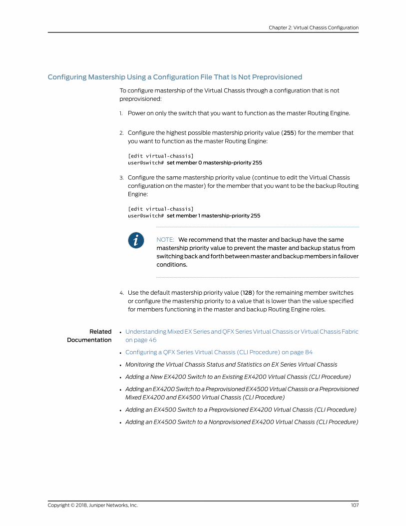
ConfiguringMastership Using a Configuration File That Is Not Preprovisioned
To configure mastership of the Virtual Chassis through a configuration that is not
preprovisioned:
1. Power on only the switch that you want to function as the master Routing Engine.
2. Configure the highest possible mastership priority value (255) for the member that
you want to function as the master Routing Engine:
[edit virtual-chassis]user@switch# setmember 0mastership-priority 255
3. Configure the samemastership priority value (continue to edit the Virtual Chassis
configuration on themaster) for themember that youwant to be the backup Routing
Engine:
[edit virtual-chassis]user@switch# setmember 1 mastership-priority 255
NOTE: We recommend that themaster and backup have the samemastership priority value to prevent themaster and backup status fromswitchingbackandforthbetweenmasterandbackupmembers in failoverconditions.
4. Use the default mastership priority value (128) for the remaining member switches
or configure the mastership priority to a value that is lower than the value specified
for members functioning in the master and backup Routing Engine roles.
RelatedDocumentation
UnderstandingMixedEXSeriesandQFXSeriesVirtualChassisorVirtualChassis Fabric
on page 46
•
• Configuring a QFX Series Virtual Chassis (CLI Procedure) on page 84
• Monitoring the Virtual Chassis Status and Statistics on EX Series Virtual Chassis
• Adding a New EX4200 Switch to an Existing EX4200 Virtual Chassis (CLI Procedure)
• AddinganEX4200Switch toaPreprovisionedEX4500VirtualChassis or aPreprovisioned
Mixed EX4200 and EX4500 Virtual Chassis (CLI Procedure)
• Adding an EX4500 Switch to a Preprovisioned EX4200 Virtual Chassis (CLI Procedure)
• Adding an EX4500 Switch to a Nonprovisioned EX4200 Virtual Chassis (CLI Procedure)
107Copyright © 2018, Juniper Networks, Inc.
Chapter 2: Virtual Chassis Configuration

Configuring the Timer for the BackupMember to Start Using Its OwnMACAddress, asMaster of a Virtual Chassis (CLI Procedure)
When a backupmember takes control of a Virtual Chassis because of a reset or other
temporary failure, the backupmember uses the MAC address of the old master switch
as the systemMAC base address. This process helps ensure a smooth transition of
mastership with no disruption to network connectivity.
The MAC persistence timer is used in situations in which the master switch is no longer
amemberof theVirtualChassisbecause it hasbeenphysically disconnectedor removed.
If the old master switch does not rejoin the Virtual Chassis before the timer elapses, the
newmaster switch starts using its ownMAC address as the system’s MAC base address.
For information regarding how the systemMAC base address is used to assign MAC
addresses to ports in a Virtual Chassis, see “Understanding MAC Address Assignment
on a Virtual Chassis” on page 65.
The default timer value is 10 minutes. Themaximum timer value is 60minutes.
You can disable the MAC persistence timer starting in Junos OS Release 12.1R3. When
theMAC persistence timer is disabled, the MAC address of the oldmaster switch is used
as the systemMAC base address; no MAC address changes occur within the Virtual
Chassis even when the old master switch is no longer a member of the Virtual Chassis
because it has been physically disconnected or removed.
To configure or modify the MAC persistence timer:
[edit virtual-chassis]user@switch# setmac-persistence-timerminutes
To disable the MAC persistence timer:
[edit virtual-chassis]user@switch# setmac-persistence-timer disable
RelatedDocumentation
Configuring a QFX Series Virtual Chassis (CLI Procedure) on page 84•
• Understanding Virtual Chassis Components on page 34
Setting an Uplink Port on an EX Series or QFX Series Switch as a Virtual Chassis Port
The procedure described in this topic can be used to set up Virtual Chassis ports (VCPs)
toconnect twoswitches togetherwithin the sameEXSeriesorQFXSeriesVirtualChassis.
Switches that can bemembers of a Virtual Chassis might have dedicated VCPs (ports
that can only be used as VCPs), default-configured VCPs (ports that are already
configured into VCPs with the default factory configuration), or ports that can be
configured into VCPs. Under certain conditions, uplink ports that are supported as VCPs
will automaticallybeconverted intoVCPswhen interconnectingamember intoanexisting
Virtual Chassis (see “Automatic Virtual Chassis Port (VCP) Conversion” on page 39).
Otherwise, youmust manually convert uplink ports into VCPs using this procedure. See
“Virtual Chassis PortOptions” onpage 38 for a list of VCPoptions on each type of switch.
Copyright © 2018, Juniper Networks, Inc.108
Virtual Chassis Feature Guide for Switches

For completedetails aboutwherea switchhasdedicatedVCPs, default-configuredVCPs,
or ports that can be configured asVCPs, andwhat transceivers and cables are supported
to use for VCP connections on that switch, see the hardware documentation for the
switch.
You typically configure an uplink port as a Virtual Chassis Port (VCP) for one of the
following reasons:
• Youwant to interconnect two switches into aVirtual Chassis that havededicatedVCPs
but are located in different wiring closets or sites, and the switches are farther apart
then themaximum length of a dedicated VCP cable.
• YouareconfiguringaVirtualChassis composedof switches that supportVirtualChassis
but do not have dedicated VCPs or default-configured VCPs. Some switches have
dedicated VCPs, which are ports that can only be used as VCPs. Some switches have
ports that are configured by default as VCPs, but can be re-configured as network
ports if desired.
• You are using dedicated or default-configured VCPs to interconnect members in a
Virtual Chassis, and want to add redundant VCP links betweenmembers using
additional ports that can be configured into VCPs.
CAUTION: If you configure an uplink port as a VCP to create a redundantlink with a dedicated VCP connection on EX4200, EX4500, or EX4550switches, toavoid traffic loopingwithin theVirtualChassis, youmust rebootthe Virtual Chassis after configuring the port conversion and cabling theVCP link. See “Troubleshooting an EX Series Virtual Chassis” on page 128for more information.
You explicitly configure VCPs to connect EX2200 switches together to form an EX2200
Virtual Chassis. See Setting a Port on an EX2200 Switch as a Virtual Chassis Port (CLI
Procedure).
You explicitly configure VCPs to connect EX2300 switches or multigigabit EX2300
switches together to form an EX2300 Virtual Chassis.
Explicitly configuring VCPs is usually not needed when configuring an EX3300 Virtual
Chassis. Uplink ports 2 and 3 on an EX3300 switch are configured as VCPs by default
and, therefore, do not require user configuration to be set as VCPs. We recommend that
you use this procedure to configure an uplink port on an EX3300 switch as a VCP only if
youconfiguredports 2and3asnetworkuplinkportsand theportsneed tobe reconfigured
as VCPs, or when ports 2 and 3 cannot be used as VCPs for some reason. You can use
this procedure to configure any uplink port on an EX3300 switch as a VCP.
Explicitly configuring VCPs is usually not needed when configuring an EX3400 Virtual
Chassis. The QSFP+ ports on EX3400 switches, which correspond to PIC (pic-slot) 1
ports 0 and 1, are configured as VCPs by default. Use this procedure only if you want to
configure an SFP+ port on an EX3400 switch as a VCP, or if you want to reconfigure a
QSFP+ port that had been configured into a network port back into a VCP.
109Copyright © 2018, Juniper Networks, Inc.
Chapter 2: Virtual Chassis Configuration

Explicitly configuring VCPs is usually not needed when configuring an EX4300 Virtual
Chassis. QSFP+ ports on EX4300 switches are configured as VCPs by default. Use this
procedure only if you want to configure an SFP+ port on an EX4300 switch as a VCP, or
if you want to reconfigure a QSFP+ port that had been configured into a network port
back into a VCP.
EX4200, EX4500, and EX4550 switches have dedicated VCPs that are usually used to
interconnect these switches into a Virtual Chassis. You can also interconnect EX4200,
EX4500,andEX4550switches thatarebeyond the reachof thededicatedVirtualChassis
cables asmembers of a Virtual Chassis by using the uplink ports—including the ports on
the SFP uplinkmodule, SFP+ uplinkmodule, or XFP uplinkmodule—and connecting the
uplink ports. To use the uplink ports or SFP network ports for interconnecting member
switches, youmust explicitly set the uplink ports as VCPs.
Explicitly setting up VCPs is required on QFX Series switches to form a Virtual Chassis.
QFX Series switches that support Virtual Chassis do not have any dedicated or
default-configured VCPs, but you can configure any non-channelized QSFP+ ports (or
QSFP28 ports, where supported) into VCPs.
When an uplink port is set as a VCP, it cannot be used for any other purpose. You can set
one port as a VCP and configure other uplink ports in trunkmode as an uplink to another
switch.
Before you set an uplink port as a VCP:
1. Verify that the port can be used as a VCP in your particular configuration. See “Virtual
Chassis Port Options” on page 38 for a summary of the VCP options on switches that
support Virtual Chassis, and the hardware documentation for each type of switch for
complete details about the ports and installed transceivers that can be used as VCPs.
2. If you are configuring an uplink module port as a VCP, if needed, install the uplink
module in the member switches that you want to interconnect.
3. Power on and connect to the switch that you plan to designate as the master of the
Virtual Chassis.
NOTE: Do not power on the other switches at this point.
4. Run EZSetup on the switch that you are configuring to be themaster. Follow the
prompts to specify the hostname and other identification, time zone, and network
properties. See Connecting and Configuring an EX Series Switch (CLI Procedure) for
details. The properties that you specify for the master apply to the entire Virtual
Chassis, includingall themember switches that you later interconnectwith themaster.
5. If you want to configure andmanage the Virtual Chassis remotely, specify the VME
global management interface. You can configure the VME global management
interface when you are setting up themaster or you can do it after completing the
Copyright © 2018, Juniper Networks, Inc.110
Virtual Chassis Feature Guide for Switches

other configuration steps for the Virtual Chassis. See Configuring the Virtual
Management Ethernet Interface for Global Management of an EX Series Virtual Chassis
(CLI Procedure).
6. Configure mastership of the Virtual Chassis by using either the nonprovisioned or
preprovisioned configuration. See “Configuring Mastership of a Virtual Chassis (CLI
Procedure)” on page 105 for details.
NOTE: AVirtual Chassis has twoRouting Engines, one in themaster role andthe other in the backup role. Therefore, we recommend that you always usecommit synchronize rather than simply commit to save configuration changes
made for a Virtual Chassis. This ensures that the configuration changes aresaved in both Routing Engines.
Before youbegin to interconnect aVirtualChassis across longdistances, suchasbetween
wiring closets:
• Prepare theexistingVirtualChassis for interconnectingwithapotentialmember switch
that is beyond the reach of a dedicated Virtual Chassis cable by setting at least one
uplink VCP on an existing member of the Virtual Chassis.
• Prepare the potential member switch for interconnecting with the existing Virtual
Chassis by setting at least one uplink VCP on the standalone switch.
You can set uplink VCPs on a standalone switch before interconnecting one link into an
existing Virtual Chassis, or set uplink VCPs for a switch after interconnecting one link into
an existing Virtual Chassis. In either case, youmust set the ports as VCPs that are used
to interconnect the switch into the Virtual Chassis for the master to detect the switch
and complete the process of adding it as a member.
NOTE: We recommend that you set up two uplink VCP connections withineach wiring closet for redundancy.
This topic describes:
1. Setting an Uplink VCP Between theMember Switches in a Virtual Chassis on page 111
2. Setting an Uplink VCP on a Standalone Switch on page 112
Setting an Uplink VCP Between theMember Switches in a Virtual Chassis
FromtheVirtual Chassis, you can set anuplink port on the localmember or ona specified
member as a VCP.
111Copyright © 2018, Juniper Networks, Inc.
Chapter 2: Virtual Chassis Configuration

NOTE: If you use the SFP+ uplink module, youmust configure all memberswitches to support either 1-gigabit SFP transceivers or 10-gigabit SFP+transceivers on EX4200 switches. See Setting the Mode on an SFP+ or SFP+MACSec Uplink Module (CLI Procedure).
To set the uplink ports for the local member switch (for example, member 0) and for a
different member switch (for example, member 1) to function as VCPs:
1. Set one uplink port of member 0 as a VCP. You do not need to specify themember
member-id option, because the command applies by default on the member where
it is executed.
user@switch> request virtual-chassis vc-port set pic-slot 1 port 0
2. Set one uplink port of member 1 as a VCP.
user@switch> request virtual-chassis vc-port set pic-slot 1 port 0member 1
This step includes themembermember-idoption,because it is executedonadifferent
member switch than the local member switch.
NOTE: You can also connect to amember switch individually using therequestsessionmembercommand,andsetaVCPlocallyonthatmember.(As in Step 1, you do not specify themember option in that case.)
Setting an Uplink VCP on a Standalone Switch
You can set an uplink VCP on a standalone switch before interconnecting the link into
an existing Virtual Chassis. Youmust set the port as a VCP for the Virtual Chassismaster
to detect the switch and complete the process of adding it as a member.
To set one uplink VCP on the potential member, which is currently operating as a
standalone switch:
1. Power on the standalone switch.
2. Setoneuplinkport asaVCP.Youdonotneed to specify themembermember-idoption,
because the command applies by default on the member where it is executed.
user@switch> request virtual-chassis vc-port set pic-slot 1 port 0
Copyright © 2018, Juniper Networks, Inc.112
Virtual Chassis Feature Guide for Switches

NOTE: If you do specify themembermember-id option, usemember ID 0.
Because the switch is not yet interconnected with the other members ofthe Virtual Chassis, its current member ID is 0. Its member ID will change
when it is interconnected with the Virtual Chassis. It does not impact thefunctioning of the uplink VCP that its VCP is set with 0 as themember ID.
The VCP has significance only on the local switch.
3. After you have set the uplink VCP on the standalone switch, physically interconnect
its uplinkportwith theVCPuplinkports of themembers in theexistingVirtualChassis.
The newmember switch reboots and joins the now expanded Virtual Chassis with a
different member ID.
NOTE: Thesetting for thenewmemberswitch'suplinkVCPremains intactand is not affected by the change of member ID.
4. If you have additional members in the second wiring closet, set a redundant VCP
uplink on another member switch by issuing the request virtual-chassis vc-port
command.
RelatedDocumentation
Configuring an EX3300 Virtual Chassis (CLI Procedure)•
• Configuring an EX4200, EX4500, or EX4550 Virtual Chassis (CLI Procedure)
• Configuring a Virtual Chassis on an EX Series Switch (J-Web Procedure)
• Example: Configuring an EX4200 Virtual Chassis Interconnected Across Multiple Wiring
Closets
• Example: Configuring an EX4200 Virtual Chassis Using a Preprovisioned Configuration
File
• Replacing a Member Switch of a Virtual Chassis Configuration (CLI Procedure) on
page 101
• Monitoring the Virtual Chassis Status and Statistics on EX Series Virtual Chassis
113Copyright © 2018, Juniper Networks, Inc.
Chapter 2: Virtual Chassis Configuration

Disabling Split andMerge in a Virtual Chassis (CLI Procedure)
The split andmerge feature is enabled by default on all EX Series switches and QFX
Series devices in a Virtual Chassis. You can disable the split andmerge feature. If you
disable the split andmerge feature and the Virtual Chassis splits, both parts of the split
Virtual Chassis configuration remain active.
In a preprovisioned Virtual Chassis, if both of the Routing Engines end up in the same
Virtual Chassis configuration after a split, the other part of the split Virtual Chassis
configuration remains inactive. If theRouting Engines end up in different parts of the split
Virtual Chassis configuration and the rest of the member switches are configured as
having linecard roles, then a backupRouting Enginemight not be selected for either part.
We recommenddisabling split andmergeonaVirtualChassiswith twomember switches.
A two-member switchVirtual Chassis that hasdisabled split andmerge can reformmore
quickly and with less complications as a result of the feature being disabled.
To disable the split andmerge feature in a Virtual Chassis:
[edit]user@switch# set virtual-chassis no-split-detection
To remove this configuration item to enable the split andmerge feature again
(recommendedwhenatwo-memberVirtualChassis isexpandedtohavemoremembers):
[edit]user@switch# delete virtual-chassis no-split-detection
RelatedDocumentation
Understanding Split and Merge in a Virtual Chassis on page 61•
Configuring Automatic Software Update on Virtual Chassis Member Switches (CLIProcedure)
Theautomatic software update feature allows you to automatically update the software
version on prospective member switches as they are added so that they can join the
Virtual Chassis.
NOTE: The version of Junos OS running on the Virtual Chassis must becompatiblewith the software running on the prospectivemember switch foran automatic software update to occur. For information on Junos OScompatibility and other automatic software update restrictions, see“Understanding Automatic Software Update on Virtual Chassis MemberSwitches” on page 64.
Before you begin, ensure that you know the name or the URL of the software package
to be used by the automatic software update feature.
Copyright © 2018, Juniper Networks, Inc.114
Virtual Chassis Feature Guide for Switches

Toconfigure theautomatic softwareupdate feature for anEXSeries orQFXSeriesVirtual
Chassis that is not a mixed-mode Virtual Chassis:
[edit]user@switch# set virtual-chassis auto-sw-update package-name package-name
NOTE: AnEX4300VirtualChassiswithacombinationofEX4300multigigabitmodel switches (EX4300-48MP) and other EX4300 switchesmust beconfigured inmixedmode, and the automatic software update feature is notsupported in this case.
NOTE: AQFX5110 Virtual Chassis is considered to be a non-mixed VirtualChassis. Because both QFX5110 andQFX5100 switches in a QFX5110 VirtualChassis run the same software image, you can use the auto-sw-update
commandwith one software package name for all members.
CAUTION: AQFX5100 switch running a Junos OS software image with“-qfx-5-” in the package filenamemust first be upgraded to a Junos OSsoftware image with “-qfx-5e-” in the package filename before it can beadded to a QFX5110 Virtual Chassis or VCF. The automatic software updateprocesscannotupdateaswitch froma“-qfx-5-” image toa“-qfx-5e-” image.See “Upgrading a QFX5100 Switch with a USB Device to Join a QFX5110Virtual Chassis or Virtual Chassis Fabric” on page 135.
After a QFX5100 switch is installed with a “-qfx-5e-” Junos OS softwareimage, the automatic software update process can successfully update theswitch automatically with a different version of a “-qfx-5e-” JunosOS imagetomatch the other members in the Virtual Chassis or VCF.
Toconfigure theautomatic softwareupdate featureonamixedVirtualChassis containing
at least one EX4200 switch andat least one EX4500or EX4550 switch, use the ex-4200
option when you are specifying a path to a package for the EX4200 switches and the
ex-4500 option when you are specifying a path to a package for the EX4500 or EX4550
switches, as follows:
[edit]user@switch# set virtual-chassis auto-sw-update ex-4200 package-name package-nameuser@switch# set virtual-chassis auto-sw-update ex-4500 package-name package-name
You do not need to specify the ex4500 option when configuring automatic software
update for a Virtual Chassis with only a combination of EX4500 and EX4550 switches,
which does not need to run in mixedmode. Specifying only a Junos OS package name
for an EX4500 switch updates the software for both EX4500 and EX4550 switches.
To configure the automatic software update feature on amixedQFX5100Virtual Chassis
composed of QFX5100 switches and at least one other supported type of device
115Copyright © 2018, Juniper Networks, Inc.
Chapter 2: Virtual Chassis Configuration
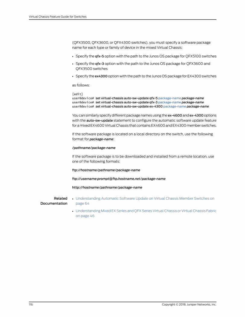
(QFX3500, QFX3600, or QFX4300 switches), youmust specify a software package
name for each type or family of device in the mixed Virtual Chassis:
• Specify the qfx-5 optionwith the path to the Junos OS package for QFX5100 switches
• Specify the qfx-3 option with the path to the Junos OS package for QFX3600 and
QFX3500 switches
• Specify theex4300optionwith thepath to the JunosOSpackage for EX4300switches
as follows:
[edit]user@device# set virtual-chassis auto-sw-update qfx-5 package-name package-nameuser@device# set virtual-chassis auto-sw-update qfx-3 package-name package-nameuser@device# set virtual-chassis auto-sw-update ex-4300 package-name package-name
Youcansimilarly specifydifferentpackagenamesusing theex-4600andex-4300options
with the auto-sw-update statement to configure the automatic software update feature
foramixedEX4600VirtualChassis thatcontainsEX4600andEX4300memberswitches.
If the software package is located on a local directory on the switch, use the following
format for package-name:
/pathname/package-name
If the software package is to be downloaded and installed from a remote location, use
one of the following formats:
ftp://hostname/pathname/package-name
ftp://username:[email protected]/package-name
http://hostname/pathname/package-name
RelatedDocumentation
Understanding Automatic Software Update on Virtual Chassis Member Switches on
page 64
•
• UnderstandingMixedEXSeriesandQFXSeriesVirtualChassisorVirtualChassis Fabric
on page 46
Copyright © 2018, Juniper Networks, Inc.116
Virtual Chassis Feature Guide for Switches

Assigning the Virtual Chassis ID to Determine Precedence During a Virtual ChassisMerge (CLI Procedure)
Every Virtual Chassis has a unique ID that is automatically assigned when the Virtual
Chassis configuration is formed. You can also explicitly assign a Virtual Chassis ID using
the set virtual-chassis id command.When two Virtual Chassis configurations attempt to
merge, the Virtual Chassis ID that you assigned takes precedence over the automatically
assigned Virtual Chassis IDs and becomes the ID for the newly merged Virtual Chassis
configuration.
To configure the Virtual Chassis ID:
[edit]user@switch# set virtual-chassis id id
RelatedDocumentation
Understanding Split and Merge in a Virtual Chassis on page 61•
Configuring Graceful Routing Engine Switchover in a Virtual Chassis (CLI Procedure)
In a Virtual Chassis, one member switch is assigned themaster role and has the master
Routing Engine. Anothermember switch is assigned the backup role and has the backup
Routing Engine. Graceful Routing Engine switchover (GRES) enables the master and
backup Routing Engines in a Virtual Chassis configuration to switch from themaster to
backupwithout interruption to packet forwarding as a hitless failover solution.When you
configure graceful Routing Engine switchover, the backup Routing Engine automatically
synchronizes with the master Routing Engine to preserve kernel state information and
the forwarding state.
To set up the Virtual Chassis configuration to use graceful Routing Engine switchover
(GRES):
1. Set up aminimum of two switches in a Virtual Chassis configuration withmastership
priority of 255:
[edit]user@switch# set virtual-chassis member 0mastership-priority 255[edit]user@switch# set virtual-chassis member 1 mastership-priority 255
2. Set up graceful Routing Engine switchover:
[edit]user@switch# set chassis redundancy graceful-switchover
Commit the configuration.
117Copyright © 2018, Juniper Networks, Inc.
Chapter 2: Virtual Chassis Configuration

NOTE: We recommend that you use the commit synchronize command to
save any configuration changes that youmake to amultimember VirtualChassis.
RelatedDocumentation
• Example: Configuring an EX4200 Virtual Chassis with a Master and Backup in a Single
Wiring Closet
• High Availability Features for EX Series Switches Overview
• Understanding EX Series Virtual Chassis Configuration on page 59
• Understanding QFX Series Virtual Chassis on page 29
Copyright © 2018, Juniper Networks, Inc.118
Virtual Chassis Feature Guide for Switches

CHAPTER 3
Virtual Chassis Routine Monitoring andTroubleshooting
• Command Forwarding Usage with an EX Series Virtual Chassis on page 119
• Verifying theMember ID, Role, and Neighbor Member Connections of a Virtual Chassis
Member on page 124
• Verifying That Virtual Chassis Ports Are Operational on page 125
• Verifying That Graceful Routing Engine Switchover Is Working in the Virtual
Chassis on page 127
• Troubleshooting an EX Series Virtual Chassis on page 128
Command Forwarding Usagewith an EX Series Virtual Chassis
Some CLI commands can be run either on all members or on a specific member of a
Virtual Chassis configuration. This functionality is referred to as command forwarding.
You can always specify that these commands be applied to all member switches in the
Virtual Chassis by using the all-members option, or to a specificmember switch by using
themember-member-id option. If neither option is specified, the default command
forwarding behavior, which varies by command, is used. See the Default row in
Table 9 on page 120 to learn the command forwarding behavior for a specific command.
For example, to collect information about a particularmember switch prior to contacting
JuniperNetworksTechnicalAssistanceCenter (JTAC), use the requestsupport information
membermember-id command to gather data for the specified member switch. If you
want to gather this data for all member switches in the Virtual Chassis, you can enter
the requestsupport informationcommand,whichbydefault uses theall-membersoption,
or the request support information all-members command.
Table 9 on page 120 provides a list of commands that can be run either on all members
of the Virtual Chassis configuration or on a specific member switch.
119Copyright © 2018, Juniper Networks, Inc.

Table 9: Commands That Can be Run on All or Specific Members of the Virtual Chassis Configuration
Defaultmember-member-idall-membersPurpose
CommandsAvailable forCommandForwarding
all-membersDisplays information for thespecified member switch.
Displaysinformation for allmembers of theVirtual Chassisconfiguration.
Use this commandwhen you contactJTAC about yourcomponentproblem. Thiscommand is theequivalent of usingthe following CLIcommands:
• show version
• show chassisfirmware
• show chassishardware
• show chassisenvironment
• show interfacesextensive (foreach configuredinterface)
• showconfiguration(excluding anySECRET-DATA)
• show systemvirtual-memory
request supportinformation
all-membersPartitions the hard disk onthe specified memberswitch.
Partitions the harddiskonallmembersof the VirtualChassisconfiguration.
Set up the hard diskforpartitioning.Afterthis command isissued, the hard diskis partitioned thenext timethesystemis rebooted. Whenthe hard disk ispartitioned, thecontents of /altrootand /altconfig aresaved and restored.All other data on thehard disk is at risk ofbeing lost.
request systempartition hard-disk
all-membersReboots the specifiedmember switch.
Reboots allmembers of theVirtual Chassisconfiguration.
Reboot JunosOS forEX Series switchesafter a softwareupgrade andoccasionally torecover fromanerrorcondition.
request systemreboot
Copyright © 2018, Juniper Networks, Inc.120
Virtual Chassis Feature Guide for Switches

Table 9: Commands That Can be Run on All or Specific Members of the Virtual Chassis Configuration (continued)
Defaultmember-member-idall-membersPurpose
CommandsAvailable forCommandForwarding
all-membersBacks up the file systemonthe specified memberswitch.
Backs up the filesystems on allmembers of theVirtual Chassisconfiguration.
Back up thecurrently runningand active filesystem.
request systemsnapshot
all-membersRuns cleanup on thespecified member switch.
Runs cleanup on allmembers of theVirtual Chassisconfiguration.
Free storage spaceon the switch byrotating log files andproposing a list offiles for deletion.User input isrequired for filedeletion.
request systemstorage cleanup
master switch onlyDisplays information for thespecified member switch.
Displaysinformation for allmembers of theVirtual Chassisconfiguration.
Display users whoare viewing thesystem log.
show log user
all-membersDisplays information for thespecified member switch.
Displaysinformation for allmembers of theVirtual Chassisconfiguration.
Display activesystem alarms.
show system alarms
all-membersDisplays information for thespecified member switch.
Displaysinformation for allmembers of theVirtual Chassisconfiguration.
Display the stateand checksumvalues for filesystems.
show system audit
all-membersDisplays information for thespecified member switch.
Displaysinformation for allmembers of theVirtual Chassisconfiguration.
Display initialmessagesgeneratedby the systemkernelupon startup. Thesemessages are thecontents of/var/run/dmesg.boot.
show systemboot-messages
121Copyright © 2018, Juniper Networks, Inc.
Chapter 3: Virtual Chassis Routine Monitoring and Troubleshooting

Table 9: Commands That Can be Run on All or Specific Members of the Virtual Chassis Configuration (continued)
Defaultmember-member-idall-membersPurpose
CommandsAvailable forCommandForwarding
all-membersDisplays information for thespecified member switch.
Displaysinformation for allmembers of theVirtual Chassisconfiguration.
Display informationabout the bufferpool that theRouting Engine usesfor local traffic.Local traffic is therouting andmanagement trafficthat is exchangedbetweentheRoutingEngine and thePacket ForwardingEngine within theswitch, as well asthe routing andmanagement trafficfrom IP (that is, fromOSPF, BGP, SNMP,pingoperations, andso on).
show system buffers
all-membersDisplays information for thespecified member switch.
Displaysinformation for allmembers of theVirtual Chassisconfiguration.
Display informationabout the active IPsockets on theRouting Engine. Usethis command toverify which serversare active on asystem and whichconnections arecurrently inprogress.
show systemconnections
all-membersDisplays information for thespecified member switch.
Displaysinformation for allmembers of theVirtual Chassisconfiguration.
Display a core filegenerated by aninternal Junos OSprocess.
show systemcore-dumps
master switch onlyDisplays information for thespecified member switch.
Displaysinformation for allmembers of theVirtual Chassisconfiguration.
Display directoryusage information.
show systemdirectory-usage
all-membersDisplaysinformation for allmembers of theVirtual Chassisconfiguration.
Display informationabout softwareprocesses that arerunning on theswitchandthathavecontrollingterminals.
show systemprocesses
Copyright © 2018, Juniper Networks, Inc.122
Virtual Chassis Feature Guide for Switches

Table 9: Commands That Can be Run on All or Specific Members of the Virtual Chassis Configuration (continued)
Defaultmember-member-idall-membersPurpose
CommandsAvailable forCommandForwarding
all-membersDisplays information for thespecified member switch.
Displaysinformation for allmembers of theVirtual Chassisconfiguration.
Display pendingsystem reboots orhalts.
show system reboot
all-membersDisplays information for thespecified member switch.
Displaysinformation for allmembers of theVirtual Chassisconfiguration.
Display informationabout the backupsoftware that islocated in the/altroot and/altconfig filesystems. To back upsoftware, use therequest systemsnapshotcommand.
show systemsnapshot
all-membersDisplays information for thespecified member switch.
Displaysinformation for allmembers of theVirtual Chassisconfiguration.
Display the JunosOSextensions loadedon your switch.
show systemsoftware
all-membersDisplays information for thespecified member switch.
Displaysinformation for allmembers of theVirtual Chassisconfiguration.
Display systemwideprotocol-relatedstatistics.
show systemstatistics
all-membersDisplays information for thespecified member switch.
Displaysinformation for allmembers of theVirtual Chassisconfiguration.
Display statisticsabout theamountoffreedisk space in theswitch's filesystems.
showsystemstorage
all-membersDisplays information for thespecified member switch.
Displaysinformation for allmembers of theVirtual Chassisconfiguration.
Display the currenttime andinformation abouthow long the switch,the switch software,and any existingprotocols have beenrunning
show system uptime
all-membersShows all users who arecurrently logged in to thespecified member switch.
Shows all userswho are currentlylogged in to anymembers of theVirtual Chassisconfiguration.
Show all users whoare currently loggedin.
show system users
123Copyright © 2018, Juniper Networks, Inc.
Chapter 3: Virtual Chassis Routine Monitoring and Troubleshooting

Table 9: Commands That Can be Run on All or Specific Members of the Virtual Chassis Configuration (continued)
Defaultmember-member-idall-membersPurpose
CommandsAvailable forCommandForwarding
all-membersDisplays information for thespecified member switch.
Displaysinformation for allmembers of theVirtual Chassisconfiguration.
Display the usage ofJunos OS kernelmemory, listed firstby size of allocationand then by type ofusage. Use showsystemvirtual-memory fortroubleshootingwithJTAC.
show systemvirtual-memory
RelatedDocumentation
Monitoring the Virtual Chassis Status and Statistics on EX Series Virtual Chassis•
• Understanding Virtual Chassis Components on page 34
• Junos OS System Basics and Services Command Reference
Verifying theMember ID, Role, andNeighborMember Connections of aVirtual ChassisMember
Purpose You can designate the role that a member performs within a Virtual Chassis or you can
allow the role tobeassignedbydefault. Youcandesignate themember ID that is assigned
to a specific switch by creating a permanent association between the switch’s serial
numberandamember ID, usingapreprovisionedconfiguration.Or youcan let themember
ID be assigned by themaster, based on the sequence in which the member switch is
powered on and on which member IDs are currently available.
The role andmember ID of themember switch are displayed on the front-panel LCD (for
switches that have an LCD) or in the output from the showvirtual-chassisCLI command.
Eachmember switch can be cabled to one or two other member switches, using either
the dedicated Virtual Chassis ports (VCPs) on the rear panel, an uplink port that has
been configured as a VCP, or an optical port that has been configured as a VCP. The
members that are cabled together are considered neighbor members.
Action To display the role andmember ID assignments using the CLI:
user@switch> show virtual-chassis
Virtual Chassis ID: 0000.e255.00e0
Mastership Neighbor List Member ID Status Serial No Model Priority Role ID, Interface
0 (FPC 0) Prsnt abc123 ex4200-48p 255 Master* 1 vcp-0 2 vcp-1
Copyright © 2018, Juniper Networks, Inc.124
Virtual Chassis Feature Guide for Switches

1 (FPC 1) Prsnt def456 ex4200-24t 255 Backup 2 vcp-0 0 vcp-1
2 (FPC 2) Prsnt abd231 ex4200-24p 128 Linecard 0 vcp-0 1 vcp-1
Meaning This output verifies that three EX4200 switches have been interconnected as a Virtual
Chassis configuration through their dedicatedVCPs to create an EX4200Virtual Chassis.
The display shows which of the VCPs is connected to which neighbor. The first port
(vcp-0) ofmember0 is connected tomember 1and the secondport ofmember0 (vcp-1)
is connected to member 2. The FPC slots for the switches are the same as themember
IDs.
TheMastership Priority values indicate that themaster and backupmembers have been
explicitly configured, because they are not using the default value (128).
NOTE: Thisexampleusesoutput fromanEX4200VirtualChassis.Theoutput,with theexceptionof theModelcolumn,wouldbe identicalonall otherVirtual
Chassis.
RelatedDocumentation
Configuring Mastership of a Virtual Chassis (CLI Procedure) on page 105•
• Configuring a QFX Series Virtual Chassis (CLI Procedure) on page 84
• Monitoring the Virtual Chassis Status and Statistics on EX Series Virtual Chassis
Verifying That Virtual Chassis Ports Are Operational
Purpose Display the status of Virtual Chassis ports (VCPs) in a Virtual Chassis or Virtual Chassis
Fabric (VCF).
NOTE: VCPsarenotdisplayedwhenyou issue the showinterfacescommand.
Action Display the VCPs:
user@switch> show virtual-chassis vc-port all-members
fpc0:--------------------------------------------------------------------------Interface Type Trunk Status Speed Neighboror ID (mbps) ID InterfacePIC / Portvcp-0 Dedicated 1 Up 32000 1 vcp-0vcp-1 Dedicated 2 Up 32000 1 vcp-1
125Copyright © 2018, Juniper Networks, Inc.
Chapter 3: Virtual Chassis Routine Monitoring and Troubleshooting

1/0 Configured 3 Up 1000 2 vcp-255/1/01/1 Configured 3 Up 1000 2 vcp-255/1/11/2 Configured 4 Up 1000 4 vcp-255/0/201/3 Configured 4 Up 1000 4 vcp-255/0/21
fpc1:--------------------------------------------------------------------------Interface Type Trunk Status Speed Neighboror ID (mbps) ID InterfacePIC / Portvcp-0 Dedicated 1 Up 32000 0 vcp-0vcp-1 Dedicated 2 Up 32000 0 vcp-11/0 Configured 3 Up 10000 3 vcp-255/1/01/1 Configured 3 Up 10000 3 vcp-255/1/1
fpc2: --------------------------------------------------------------------------Interface Type Trunk Status Speed Neighboror ID (mbps) ID InterfacePIC / Portvcp-0 Dedicated 1 Up 32000 3 vcp-0vcp-1 Dedicated 2 Up 32000 3 vcp-11/0 Configured 3 Up 1000 0 vcp-255/1/01/1 Configured 3 Up 1000 0 vcp-255/1/11/2 —1 Down 10001/3 —1 Down 1000
fpc3: --------------------------------------------------------------------------Interface Type Trunk Status Speed Neighboror ID (mbps) ID InterfacePIC / Portvcp-0 Dedicated 1 Up 32000 2 vcp-0vcp-1 Dedicated 2 Up 32000 2 vcp-11/0 Configured 3 Up 10000 1 vcp-255/1/01/1 Configured 3 Up 10000 1 vcp-255/1/1
fpc4: --------------------------------------------------------------------------Interface Type Trunk Status Speed Neighboror ID (mbps) ID InterfacePIC / Portvcp-0 Dedicated 1 Down 32000vcp-1 Dedicated 2 Down 320000/20 Configured 3 Up 1000 0 vcp-255/1/20/21 Configured 3 Up 1000 0 vcp-255/1/3
Meaning The dedicated VCPs are displayed as vcp-0 and vcp-1. The uplink interfaces that have
been set as uplink VCPs are displayed as 1/0, 1/1, 1/2, and 1/3. The network interfaces
thathavebeensetasVCPsaredisplayedas0/20and0/21. Theneighbor interfacenames
of uplink and network VCPs are of the form vcp-255/pic/port—for example, vcp-255/1/0.
In that name, vcp-255 indicates that the interface is a VCP, 1 is the uplink PIC number,
and 0 is the port number. The fpc number is the same as themember ID. The trunk ID is
a positive number ID assigned to the link aggregation group (LAG) formed by the Virtual
Chassis. If no LAG is formed, the value is –1.
Copyright © 2018, Juniper Networks, Inc.126
Virtual Chassis Feature Guide for Switches

NOTE: Thisexampleusesoutput fromanEX4200VirtualChassis.Theoutputis similar on all other types of Virtual Chassis or for a VCF.
RelatedDocumentation
Monitoring the Virtual Chassis Status and Statistics on EX Series Virtual Chassis•
• Configuring an EX3300 Virtual Chassis (CLI Procedure)
• Configuring an EX4200, EX4500, or EX4550 Virtual Chassis (CLI Procedure)
• Configuring a Virtual Chassis on an EX Series Switch (J-Web Procedure)
• ConfiguringaMixedVirtualChassiswithEX4200,EX4500,andEX4550MemberSwitches
(CLI Procedure)
Verifying That Graceful Routing Engine Switchover IsWorking in the Virtual Chassis
Purpose Verify that aGraceful Routing Engine switchover (GRES) between twomember switches
acting as the master and backup routing engines in a Virtual Chassis has occurred.
Action On themaster switch, verify the member ID of the backup Routing Engine:
{master:0}user@switch> show virtual-chassisVirtual Chassis ID: 5efa.4b7a.aae6 Mastership Neighbor List Member ID Status Serial No Model priority Role ID Interface0 (FPC 0) Prsnt BM0208105281 ex4200-24t 255 Master* 1 vcp-0 1 (FPC 1) Prsnt BP0208192350 ex4200-48t 255 Backup 0 vcp-0
Member ID for next new member: 2 (FPC 2)
1. Connect to the backup Routing Engine:
{master:0}user@switch> request sessionmember 1
{backup:1}user@switch>
2. Verify that the backup Routing Engine is ready for switchover onmember ID 1:
{backup:1}user@switch> show system switchover
Graceful switchover: OnConfiguration database: ReadyKernel database: ReadyPeer state: Steady State
127Copyright © 2018, Juniper Networks, Inc.
Chapter 3: Virtual Chassis Routine Monitoring and Troubleshooting

3. Switch the current backup Routing Engine to master Routing Engine:
NOTE: Youmustwaitaminimumof twominutesbetweenRoutingEnginefailovers for the Routing Engines to synchronize.
{backup:1}user@switch> request chassis routing-enginemaster acquire
4. Verify that the master and backup Routing Engines have switched roles:
NOTE: Member ID 1 isnowthemasterandmember ID0 isnowthebackup.
{master:1}user@switch> show virtual-chassis
Virtual Chassis ID: 5efa.4b7a.aae6 Mastership Neighbor List
Member ID Status Serial No Model priority Role ID Interface0 (FPC 0) Prsnt BM0208105281 ex4200-24t 255 Backup 1 vcp-0
1 (FPC 1) Prsnt BP0208192350 ex4200-48t 255 Master* 0 vcp-0
Member ID for next new member: 2 (FPC 2)
Meaning With graceful Routing Engine switchover enabled, when you initiated a switchover from
the backup Routing Engine, the backup Routing Engine became themaster and the
master Routing Engine became the backup.
RelatedDocumentation
Configuring Graceful Routing Engine Switchover in a Virtual Chassis (CLI Procedure)
on page 117
•
Troubleshooting an EX Series Virtual Chassis
This topic describes the following troubleshooting issues for a Virtual Chassis:
• A Disconnected Member Switch's ID Is Not Available for Reassignment on page 129
• LoadFactoryDefaultDoesNotCommitonaMultimemberVirtualChassis onpage 129
• The Member ID Persists When a Member Switch Is Disconnected From a Virtual
Chassis on page 129
Copyright © 2018, Juniper Networks, Inc.128
Virtual Chassis Feature Guide for Switches

• AMember Switch Is Not Participating in a Mixed Virtual Chassis on page 130
• Unknown Traffic Looping Occurs After Configuring an Uplink Port as a Redundant
VCP with a Dedicated VCP on page 131
ADisconnectedMember Switch's ID Is Not Available for Reassignment
Problem Description: You disconnected a switch from the Virtual Chassis, but the disconnected
switch’s member ID is still displayed in the status output. You cannot reassign that
member ID to another switch.
Solution When you disconnect a member of a Virtual Chassis configuration, the master retains
the member ID andmember configuration in its configuration database. Output from
the show virtual-chassis command continues to display the member ID of the
disconnectedmember with a status of NotPrsnt.
If want to permanently disconnect the member switch, you can free up themember ID
by using the request virtual-chassis recycle command. This will also clear the status of
that member.
Load Factory Default Does Not Commit on aMultimember Virtual Chassis
Problem Description: The load factory-default command fails on amultimember Virtual Chassis.
Solution The load factory-default command is not supported on amultimember Virtual Chassis
configuration. For information on how to revert the switches in the Virtual Chassis to
factorydefault settings, seeReverting to theDefault FactoryConfiguration for theEXSeries
Switch.
TheMember ID PersistsWhen aMember Switch Is Disconnected From a Virtual Chassis
Problem Description:GigabitEthernet interfaces retain theirpreviousslotnumberswhenamemberswitch is disconnected from the Virtual Chassis.
Solution If a switchhadbeenpreviously connectedasamemberofaVirtualChassis configuration,
it retains the member ID that it was assigned as amember of that configuration even
after it is disconnected and operating as a standalone switch. The interfaces that were
configured while the switch was amember of the Virtual Chassis configuration retain
the old member ID as the first digit of the interface name.
For example, if the switch was previously member 1, its interfaces are named ge-1/0/0
and so on.
To change the switch’smember ID, so that itsmember ID is0, and to rename the switch’s
interfaces accordingly:
1. To change themember ID to 0:
129Copyright © 2018, Juniper Networks, Inc.
Chapter 3: Virtual Chassis Routine Monitoring and Troubleshooting

user@switch> request virtual-chassis renumbermember-id 1 new-member-id 0
2. To rename the interfaces to match the newmember ID:
[edit virtual-chassis]user@switch# replace pattern ge-1/ with ge-0/
AMember Switch Is Not Participating in aMixed Virtual Chassis
Problem Description:Amember switch in amixedVirtual Chassis is not participating in theVirtualChassis. The show virtual-chassis output indicates the member switch status is Inactive
or NotPrsnt.
This issue is most likely to occur immediately after you have cabled amixed Virtual
Chassis.
Solution The Virtual Chassis mode on the switch might not be set tomixedmode. If the member
switch is an EX4500 switch and is cabled into the Virtual Chassis through the dedicated
Virtual Chassis port (VCP), the PICmodemight also be set to Intraconnect instead of
virtual-chassis.
To verify the Virtual Chassis mode:
user@switch> show virtual-chassis modefpc0:--------------------------------------------------------------------------Mixed Mode: Enabledfpc1:--------------------------------------------------------------------------Mixed Mode: Enabledfpc2:--------------------------------------------------------------------------Mixed Mode: Enabledfpc3:--------------------------------------------------------------------------Mixed Mode: Enabledfpc4:--------------------------------------------------------------------------Mixed Mode: Disabledfpc5:--------------------------------------------------------------------------Mixed Mode: Enabled
To change the Virtual Chassis mode on amember switch (in this case, member ID 4) to
mixedmode:
user@switch> request virtual-chassis modemixedmember 4
(EX4500 switch only) To verify the PICmode:
user@switch> show chassis pic-modefpc0:-------------------------------------------------------------------------- Pic Mode: Not-Applicable
Copyright © 2018, Juniper Networks, Inc.130
Virtual Chassis Feature Guide for Switches

fpc1:-------------------------------------------------------------------------- Pic Mode: Not-Applicablefpc2:-------------------------------------------------------------------------- Pic Mode: Not-Applicablefpc3:-------------------------------------------------------------------------- Pic Mode: Not-Applicablefpc4:-------------------------------------------------------------------------- Pic Mode: PIC 3: Intraconnectfpc5:-------------------------------------------------------------------------- Pic Mode: PIC 3: virtual-chassis
To change the PICmode on an EX4500 switch to virtual-chassismode (in this case,
member ID 4):
user@switch> request chassis pic-mode virtual-chassis member 4
Themember switchmust be rebooted for the Virtual Chassis mode or PICmode setting
change to take effect. To reboot the member switch (in this case, member ID 4):
user@switch> request system rebootmember 4
Unknown Traffic Looping Occurs After Configuring an Uplink Port as a Redundant VCPwith aDedicated VCP
Problem Description: In a Virtual Chassis comprised of EX4200, EX4500, or EX4550 switches,you observe unrecoverable looping of unknown unicast or multicast traffic following the
additionofa redundantVCP linkbetweentwomemberswitches,whenthe twomembers
are connected by a dedicated VCP link and the redundant link was created by converting
uplink ports to VCPs.
This behavior can occur whether the redundant VCP link is created by setting the ports
manually as VCPs or if the automatic VCP conversion feature is invoked and converts
the ports into VCPs automatically.
Solution Reboot theVirtual Chassis to properly detect the convertedVCPas a redundant linkwith
the dedicated VCP link.
After the conversion from a network port to a VCP, the egress filter table is not updated
and the redundant VCP remains enabled for forwarding, which causes the looping
behavior. The reboot process detects the converted port as a VCP and brings it up as
disabled for forwarding.
As a result, we do not recommend connecting redundant converted uplink VCP ports
betweenmembers already connected by dedicated VCPs on an active Virtual Chassis;
instead, plan to add redundant uplink VCP connections during amaintenance window
that can include a Virtual Chassis reboot cycle. This recommendation also applies when
addinganewmember toanexistingactiveVirtualChassiswhereyouareadding redundant
131Copyright © 2018, Juniper Networks, Inc.
Chapter 3: Virtual Chassis Routine Monitoring and Troubleshooting

VCP links between the newmember and one of its neighbors that mix dedicated VCPs
and converted uplink VCPs.
RelatedDocumentation
• Monitoring the Virtual Chassis Status and Statistics on EX Series Virtual Chassis
• Configuring an EX4200, EX4500, or EX4550 Virtual Chassis (CLI Procedure)
• ConfiguringaMixedVirtualChassiswithEX4200,EX4500,andEX4550MemberSwitches
(CLI Procedure)
• Configuring a Virtual Chassis on an EX Series Switch (J-Web Procedure)
Copyright © 2018, Juniper Networks, Inc.132
Virtual Chassis Feature Guide for Switches

CHAPTER 4
Upgrading Software on a Virtual Chassis
• Understanding Software Upgrades in a Virtual Chassis on page 133
• Upgrading a QFX5100 Switch with a USB Device to Join a QFX5110 Virtual Chassis or
Virtual Chassis Fabric on page 135
• Understanding Nonstop Software Upgrade on a Virtual Chassis and Mixed Virtual
Chassis on page 140
• Configuring Line-Card Upgrade Groups for Nonstop Software Upgrade (CLI
Procedure) on page 145
• Upgrading Software on a Virtual Chassis and Mixed Virtual Chassis Using Nonstop
Software Upgrade on page 147
Understanding Software Upgrades in a Virtual Chassis
This topic discusses software upgrades on EX Series and QFX Series Virtual Chassis,
except EX8200 Virtual Chassis. For information on software upgrades on an EX8200
Virtual Chassis, see Understanding Software Upgrades in an EX8200 Virtual Chassis. For
information on software upgrades on a Virtual Chassis Fabric (VCF), see Understanding
Software Upgrades in a Virtual Chassis Fabric.
In a Virtual Chassis, eachmember switch must be running the same version of Juniper
Networks Junos operating system (Junos OS) that supports Virtual Chassis. You can
install a new Junos OS release on the entire Virtual Chassis or on a particular member in
the Virtual Chassis by using the same CLI command that you use to install Junos OS on
standalone switches—the request system software add command.
In a mixed Virtual Chassis, the member switches must also be running the same version
of Junos OS. Youmight need to specify multiple Junos OS images whenmanually or
automatically upgrading amixed Virtual Chassis. For example, an EX4200 switch runs
a different Junos OS image than an EX4500 or EX4550 switch, or an EX4300 switch
runs a different Junos OS image than a QFX5100 switch in a QFX5100 Virtual Chassis.
You can upgrade all member switches simultaneously by specifying a path to multiple
Junos OS images in the same request system software add command.
133Copyright © 2018, Juniper Networks, Inc.
NOTE: Some switch platforms can run the same Junos OS image. Forexample, you do not need to usemultiple Junos OS images when updatinga Virtual Chassis with a combination of EX4500 and EX4550 switches, or aVirtual Chassis with a combination of QFX3500 and QFX3600 switches.
You can also use the following features to upgrade software onmembers of a Virtual
Chassis:
• Automatic Software Updates on page 134
• Nonstop Software Upgrade on page 134
Automatic Software Updates
You can use the automatic software update feature on a non-mixed or mixed Virtual
Chassis to automatically update the Junos OS version onmember switches as you add
them to a Virtual Chassis. See “Understanding Automatic Software Update on Virtual
Chassis Member Switches” on page 64 for more information.
If you are not configuring the automatic software update feature, we recommend that
you update the newmember switch to the version of Junos OS running on the Virtual
Chassis before adding the member switch to the Virtual Chassis.
Nonstop Software Upgrade
Youcanalsousenonstopsoftwareupgrade(NSSU)toupgrade JunosOSonallmembers
of a Virtual Chassis for EX Series and QFX Series Virtual Chassis that support NSSU.
NSSU provides an orderly upgrade of eachmember of the Virtual Chassis and takes
advantage of graceful Routing Engine switchover, nonstop active routing, and link
aggregation to minimize traffic disruption during the upgrade.
For more information about NSSU and the Virtual Chassis that support this feature, see:
• Understanding Nonstop Software Upgrade on a Virtual Chassis and Mixed Virtual
Chassis on page 140
• Upgrading Software on a Virtual Chassis and Mixed Virtual Chassis Using Nonstop
Software Upgrade on page 147
• (For legacy EX Series switches in a Virtual Chassis)Upgrading Software Using Nonstop
SoftwareUpgradeonEXSeriesVirtualChassis andMixedVirtualChassis (CLIProcedure)
RelatedDocumentation
Understanding Virtual Chassis Components on page 34•
• Configuring Automatic Software Update on Virtual Chassis Member Switches (CLI
Procedure) on page 114
• Installing Software on an EX Series Switch with a Single Routing Engine (CLI Procedure)
• Installing Software on a Mixed Virtual Chassis with EX4200, EX4500, and EX4550
Switches (CLI Procedure)
Copyright © 2018, Juniper Networks, Inc.134
Virtual Chassis Feature Guide for Switches

Upgrading a QFX5100 Switch with a USB Device to Join a QFX5110 Virtual Chassis orVirtual Chassis Fabric
Use this procedure to upgrade a standalone QFX5100 switch running “QFX 5 Series”
Junos OS software to a “QFX 5e Series” software image that enables the QFX5100 to
join a QFX5110 Virtual Chassis or Virtual Chassis Fabric (VCF).
A QFX5110 Virtual Chassis or VCF can be composed of a combination of QFX5110 and
QFX5100 switches thatmust be running compatible JunosOS “QFX 5e Series” software.
This procedure explains how to identify the compatible install package for QFX5100
switches, create a USB boot device as the installation media, and use the boot device
to install the software on a QFX5100 switch. After installing the new software image,
when you reboot the QFX5100, the switch is running a compatible software image and
can be successfully added into aQFX5110 Virtual Chassis or VCF. Upgrading using a USB
device is required in this case due to the differences in the boot structure and host OS
software of the two types of devices.
NOTE: If a QFX5100 switch is already running a ”QFX 5e Series” image(software package filename contains the string “-qfx-5e-”), you are notrequired to use this procedure to upgrade the switch before adding it to aQFX5110 Virtual Chassis or VCF. The Virtual Chassis or VCF can successfullyupdate aQFX5100member to the same version of JunosOS using the usualsupported software updatemethods as needed during initial configurationor when adding or replacingmembers. See “Understanding SoftwareUpgrades in a Virtual Chassis” on page 133 andUnderstanding SoftwareUpgrades in a Virtual Chassis Fabric.
This topic describes the following tasks:
• Identifying Compatible Software for QFX5100 Switches to Run in a QFX5110 Virtual
Chassis or VCF on page 135
• Creating a USB Boot Device for a QFX5100 Switch on page 137
• UpgradingaQFX5100Switch fromJunosOS“QFX5Series” to “QFX5eSeries”Software
Using a USB Boot Device on page 139
Identifying Compatible Software for QFX5100 Switches to Run in a QFX5110 Virtual Chassisor VCF
StandaloneQFX5100switches traditionally run JunosOSsoftware labeled “QFX5Series”
on the software download page, and the corresponding install media and installation
software package file names include the string “-qfx-5-”. For example:
install-media-qfx-5-17.2R1.13.tgzjinstall-host-qfx-5-17.2R1.13-signed.tgz
QFX5110 switches run JunosOS software labeled “QFX 5e Series” (or simply “5e Series”)
on the software download page, and employ a secure-boot method at startup that is
135Copyright © 2018, Juniper Networks, Inc.
Chapter 4: Upgrading Software on a Virtual Chassis

not used by QFX5100members running a “-qfx-5-” or a “-qfx-5e-” software image. As a
result, the corresponding install media and software package filenames for QFX5110
switches include the distinguishing strings “-qfx-5e-” and “-secure-”. For example:
install-media-host-usb-qfx-5e-x86-64-17.2R1.13-secure.tgzjinstall-host-qfx-5e-x86-64-17.2R1.13-secure-signed.tgz
BothQFX5110 andQFX5100 switches can run the same “-qfx-5e-” software images, and
when inter-operating inaVirtualChassisorVCF, theymustbe running thesame“-qfx-5e-”
software imagethatautomaticallyeitheremploys thesecure-bootmethod(whenbooting
onQFX5110switches)ordoesnot (whenbootingonQFX5100switches).Due toplatform
and image differences, for a QFX5100 running a “-qfx-5-” image to successfully join a
QFX5110 Virtual Chassis or VCF, youmust initially upgrade the QFX5100 switch to run a
“-qfx-5e-” image using a USB boot devicewithout using the secure-boot method.
Install media packages with or without the secure-boot method that install the same
“-qfx-5e-” software image for both switch types have the same filename, except the
install media filename with the secure-boot method includes the “-secure-” keyword,
and the installmedia filenameforwithout thesecure-bootmethoddoesnot. Forexample,
the following install media packages install the same software image for QFX5110 and
QFX5100 switches, respectively, but only the first install media package uses the secure
boot method during the installation:
Install media package for QFX5110members (with the secure-boot method):
install-media-host-usb-qfx-5e-x86-64-17.3R1.6-secure-signed.tgz
Compatible installmedia package forQFX5100switches (without using the secure-boot
method):
install-media-host-usb-qfx-5e-x86-64-17.3R1.6-signed.tgz
As a result, when creating the USB boot device to upgrade a QFX5100, you download
the install media filenamewithout the “secure” keyword that otherwise matches the
software package name for the image running on the QFX5110 switches in your Virtual
Chassis or VCF. For example:
install-media-host-usb-qfx-5e-x86-64-17.3R1.6-signed.tgz
After aQFX5100 switch is upgraded to a “-qfx-5e-” image using this procedure, the same
software image updates can be installed on either type of switch in the Virtual Chassis
orVCF fromthecorresponding “jinstall-host-qfx-5e-” install package filewith the “secure”
keyword. When the image boots, it determines whether or not to use the secure-boot
method based on the type of switch on which it is running. The QFX5110 Virtual Chassis
or VCF can also successfully update the member, if necessary, using the automatic
software update feature during configuration or when adding or replacing members.
Copyright © 2018, Juniper Networks, Inc.136
Virtual Chassis Feature Guide for Switches

NOTE: If you remove a QFX5100 switch from aQFX5110 Virtual Chassis orVCF and want to revert the QFX5100 switch to a “-qfx-5-” software imageto run as a standalone switch, you similarly need to reinstall the image ontheswitchusingaUSBbootdevicewitha “qfx-5-” installmedia file thatdoesnot use the secure-boot method.
Creating a USB Boot Device for a QFX5100 Switch
Use the followingprocedure to create aUSBboot devicewith a JunosOS ”QFX5eSeries”
install media package (contains “-qfx-5e-” in the package filename) for a QFX5100
switch. You can then use the USB boot device upgrade a QFX5100 switch to run the
corresponding image.
NOTE: You can create the USB boot device on the switch you want toupgrade, onanother JuniperNetworks switchor router, or onanyPCor laptopthat supports Linux. The following steps describe creating the boot devicefrom a Junos OS device, andmight differ based on the device used to createthe boot device.
Before you begin, download the installation media file from
https://www.juniper.net/customers/support/ to the device where you are creating the
boot device. The installmedia filename should include the string “-qfx-5e-” for the same
JunosOS releaseas theQFX5110VirtualChassis orVCF, butwithouta “-secure-” keyword
in the filename, becauseQFX5100 switchesmust initially be upgradedwithout using the
same secure-boot method employed by QFX5110 switches.
NOTE: The Junos OS software running on the QFX5110members must bethe “-qfx-5e-” image that uses the secure-bootmethod, so the installmediaand package filenames used on QFX5110 switches include the “-secure-”keyword. After initial USB installation of a “-qfx-5e-” software image on aQFX5100 switch, the same software image that supports secure boot runson either type of switch, anddetermines the appropriate bootmethod to usebased on the type of switch onwhich it is running. As a result, for subsequentupdates, you candirectly install the same imagewith the “-secure-” keywordon both QFX5110 and QFX5100 switches in your Virtual Chassis or VCF.
On a Junos OS device where you are creating the USB boot device:
1. Use FTP to copy the installation media file into the /var/tmp directory.
2. Insert the USB storage device into the USB port.
3. From the Junos OS command-line interface (CLI), start the shell:
user@device> start shell
137Copyright © 2018, Juniper Networks, Inc.
Chapter 4: Upgrading Software on a Virtual Chassis

%
4. Switch to the root account using the su command:
% suPassword: password
NOTE: The password is the root password for the device on which youare creating the boot media. If you logged in to the device as root, you donot need to perform this step.
5. (Optional) Before copying the installationmedia file to theUSBdevice, erase theboot
sector of the USB device. In some cases, depending on how the USB device was
formatted previously, this step can help avoid unexpected behavior during the USB
boot process. For example, enter the following command:
root@device% dd if=/dev/zero of=/dev/da1 count=2020+0 records in20+0 records out10240 bytes (10 kB) copied, 0.008281 seconds, 1.2 MB/s
6. Enter the following command to copy the installation media file (see “Identifying
Compatible Software for QFX5100 Switches to Run in a QFX5110 Virtual Chassis or
VCF” on page 135) to the USB device:
root@device% dd if=/var/tmp/filename of=/dev/da1 bs=1m
The device writes the installation media image to the USB device. For example:
root@device% dd if=install-media-host-qfx-5e-17.3R1.5-domestic.img of=/dev/da0 bs=1m1399+0 records in1399+0 records out1466957824 bytes transferred in 394.081902 secs (3722469 bytes/sec)
7. Log out of the shell:
root@device% exit% exituser@device>
8. Remove the USB storage device from the USB port.
You can now use the USB storage device to install the “-qfx-5e-” Junos OS software
image on a QFX5100 switch.
Copyright © 2018, Juniper Networks, Inc.138
Virtual Chassis Feature Guide for Switches

Upgrading aQFX5100Switch from JunosOS “QFX5Series” to “QFX5eSeries” SoftwareUsinga USB Boot Device
A standalone QFX5100 switch running “QFX 5 Series” software must be upgraded to
“QFX 5e Series” software before the switch can join a QFX5110 Virtual Chassis or VCF.
The upgrade requires booting and installing the software using a USB boot device.
Before you begin, have a USB boot device ready with the required Junos OS software
install package as described in “Creating a USB Boot Device for a QFX5100 Switch” on
page 137. The upgrade process overwrites the contents of the internal flash storage on
the QFX5100 switch, so if desired, before proceeding with the upgrade, save existing
configuration, backup configurations, and other stored files to a remote system, server,
or other storage device. Then proceed as follows:
1. Insert theUSBbootdevice intoaUSBporton theQFX5100switchyouneed toupgrade,
and power-cycle the QFX5100 switch.
2. The switch comes up, booting from the USB device and running the Juniper Linux
Installer. The installer menu prompts you to with the following options:
Juniper Linux Installer - (c) Juniper Networks 2014RebootInstall Juniper Linux PlatformBoot to host shell [debug]
Tab through the options to select Install Juniper Linux Platform, and press Enter.
3. The installer displays statusmessages during the install process, creates and formats
the local storage partitions, and installs the host OS and Junos OS software on the
switch.
When installation is complete, the installer displays a list of boot options, and after
a few seconds automatically selects the default option to boot Juniper Linux. The
switch boots the host OS and automatically selects and brings up Junos OS. Upon
completion of the install and reboot process, the switch displays the Junos OS login
prompt.
4. Log in to Junos OS on the switch, enter operational mode, and verify that the new
versionof softwarehasbeenproperly installedby running theshowversioncommand.
user@switch> show version
After the QFX5100 switch is running the “-qfx-5e-” software image, you can continue
with any other configuration and setup to add the QFX5100 to a QFX5110 Virtual
Chassis or VCF, such as configuring the Virtual Chassis ports (VCPs).
RelatedDocumentation
UnderstandingMixedEXSeriesandQFXSeriesVirtualChassisorVirtualChassis Fabric
on page 46
•
• Configuring a QFX Series Virtual Chassis (CLI Procedure) on page 84
139Copyright © 2018, Juniper Networks, Inc.
Chapter 4: Upgrading Software on a Virtual Chassis

• Understanding Virtual Chassis Fabric Configuration
Understanding Nonstop Software Upgrade on a Virtual Chassis andMixed VirtualChassis
Nonstop software upgrade (NSSU) enables you to upgrade the software running on all
member switches in a Virtual Chassis with minimal network traffic disruption during the
upgrade. This topic introduces NSSU on EX Series and QFX Series Virtual Chassis that
support this feature, except EX8200Virtual Chassis. For information on usingNSSUwith
an EX8200 Virtual Chassis, see Upgrading Software on an EX8200 Virtual Chassis Using
NonstopSoftwareUpgrade (CLI Procedure). For information on usingNSSUwith aVirtual
Chassis Fabric (VCF), see Understanding Nonstop Software Upgrade on a Virtual Chassis
Fabric.
NOTE: Because NSSU upgrades the software on each Virtual Chassis andmixed Virtual Chassis member one at a time, an upgrade using NSSU cantake longer thananupgradeusing the requestsystemsoftwareaddcommand.
Youcan reduce theamountof timeanupgrade takesbyconfiguring line-cardupgradegroups.ThemembersofaVirtualChassisorVCF inanupgradegroupare upgraded simultaneously, reducing the amount of time it takes tocomplete an upgrade. See “Configuring Line-Card Upgrade Groups forNonstop Software Upgrade (CLI Procedure)” on page 145.
This topic covers:
• Benefits of NSSU on page 140
• Requirements for Performing an NSSU on page 141
• How an NSSUWorks on a Virtual Chassis and Mixed Virtual Chassis on page 142
• NSSU Limitations on page 143
• NSSU and Junos OS Release Support on page 144
• Overview of NSSU Configuration and Operation on page 144
Benefits of NSSU
• No disruption to the control plane—NSSU uses graceful Routing Engine switchover
(GRES) (and nonstop active routing (NSR) on applicable platforms) to ensure no
disruption occurs to the control plane. During the upgrade process, interface, kernel,
and routing protocol information is preserved.
• Minimal disruption to network traffic—NSSUminimizes network traffic disruption by
upgradingmember switches one at a time, enabling themaster and backupmembers
to maintain their master and backup roles (althoughmastership will change) without
disruption to traffic, and permitting traffic to continue to flow throughmembers in the
linecard role that are not being upgraded.
Copyright © 2018, Juniper Networks, Inc.140
Virtual Chassis Feature Guide for Switches

Requirements for Performing an NSSU
The following are requirements for performing an NSSU for a Virtual Chassis or mixed
Virtual Chassis:
• All Virtual Chassis or mixed Virtual Chassis members and all Routing Enginesmust be
running the same Junos OS release.
• Graceful Routing Engine switchover (GRES)must be enabled.
• Nonstop active routing (NSR)must be enabled for applicable platforms.
Although nonstop bridging (NSB) is not required to perform anNSSU, we recommend
enabling NSB before performing an NSSU on applicable platforms. Enabling NSB
ensures thatallNSB-supportedLayer2protocolsoperateseamlesslyduring theRouting
Engine switchover that is part of the NSSU. In releases prior to Junos OS Release 16.1,
see Configuring Nonstop Bridging on Switches (CLI Procedure).
• Forminimal traffic disruption, youmust configure link aggregation groups (LAGs) such
that the member links of each LAG reside on different Virtual Chassis or mixed Virtual
Chassis members. When onemember link of a LAG is down, the remaining links are
up, and traffic continues to flow through the LAG.
NOTE: When an EX Series switch in amixed Virtual Chassis is upgradedto Junos OS Release 15.1 or later from a release earlier than Release 15.1,there might be a drop in traffic for up to 60 seconds.
The following are requirements for the Virtual Chassis ormixed Virtual Chassismembers
being upgraded using NSSU:
• The Virtual Chassis or mixed Virtual Chassis members must be connected in a ring
topology so that nomember is isolated as a result of anothermember being rebooted.
This topology prevents the Virtual Chassis from splitting during an NSSU.
• The Virtual Chassis or mixed Virtual Chassis master and backupmust be adjacent to
each other in the ring topology. Adjacency permits the master and backup to always
be in sync, even when the switches in linecard roles are rebooting.
• TheVirtualChassis ormixedVirtualChassismustbepreprovisionedso that the linecard
role has been explicitly assigned to member switches acting in a linecard role. During
an NSSU, the Virtual Chassis andmixed Virtual Chassis membersmustmaintain their
roles—themaster and backupmustmaintain theirmaster and backup roles (although
mastershipwill change), and the remaining switchesmustmaintain their linecard roles.
• A two-member Virtual Chassis or mixed Virtual Chassis must have no-split-detection
configured so that the Virtual Chassis or mixed Virtual Chassis does not split when an
NSSU upgrades amember.
141Copyright © 2018, Juniper Networks, Inc.
Chapter 4: Upgrading Software on a Virtual Chassis

NOTE: For the EX4300 Virtual Chassis, you should enable thevcp-no-hold-time statementat the [edit virtual-chassis]hierarchy level before
performing a software upgrade using NSSU. If you do not enable thevcp-no-hold-time statement, the Virtual Chassis might split during the
upgrade. A split Virtual Chassis can cause disruptions to your network, andyoumight have tomanually reconfigure your Virtual Chassis after the NSSUif the split andmerge feature was disabled. For more information about asplitVirtualChassis, see “UnderstandingSplit andMerge inaVirtualChassis”on page 61
How an NSSUWorks on a Virtual Chassis andMixed Virtual Chassis
When you request an NSSU on a Virtual Chassis or mixed Virtual Chassis:
1. The Virtual Chassis or mixed Virtual Chassis master verifies that:
• The backup is online and running the same software version.
• Graceful Routing Engine switchover (GRES) is enabled, and, if applicable, nonstop
active routing (NSR) is enabled.
• The Virtual Chassis or mixed Virtual Chassis member has a preprovisioned
configuration.
2. Themaster transfers the new software image to the backup and remaining linecard
role members in sequence using rcp.
(For QFX5100 Virtual Chassis only) Starting with Junos OS Release 14.1X53-D40, to
optimize the time needed to complete an NSSU operation for a Virtual Chassis, the
master uses parallel rcp sessions to copy the new software to multiple members at
a time (rather thanwaiting for the copyoperation to complete to eachmemberbefore
starting to copy the software image to the next member). The number of parallel
copyoperations isdeterminedbyadefaultalgorithmbasedon thenumberofmembers
in the Virtual Chassis, or you can configure a specific number using the rcp-count
configuration statement. See rcp-count for details.
NOTE: If copying the new software to anymember fails, NSSUaborts theupgrade process for the entire Virtual Chassis without rebooting anymembers, and logs the error condition. Starting with Junos OS Release14.1X53-D40, after anNSSUcopyof thenewsoftware image toamemberfails, themaster performsanadditional error recoverymeasure to removethe new software from themembers to which it was already transferred.
3. Themaster restarts thebackupwith thenewsoftware, and thebackup resynchronizes
with the master.
Copyright © 2018, Juniper Networks, Inc.142
Virtual Chassis Feature Guide for Switches

4. Themaster loads and reboots member switches that are in the linecard role, one at
a time. Themaster waits for eachmember to become online and active running the
new software before rebooting the next member.
• If you configured upgrade groups, the Virtual Chassis or VCFmembers in the first
upgrade group load the new image and restart.When themembers in that upgrade
group are online again, themembers in the next upgrade group load the new image
and restart.
• Traffic continues to flow through the other members during this process.
5. Rebooting continues until all active members have restarted with the new software.
NOTE: If any linecard role member fails to reboot successfully, NSSUaborts the upgrade process and logs the error condition. In this case, toavoid Virtual Chassis instability, you should either back out the partialupgrade by restoring the old software and rebooting themembers thatwere already rebooted with the new software, or try tomanually rebootall members with the new software that was copied to them, so allmembers come online again running the same version of the software.
Startingwith JunosOSRelease 14.1X53-D40,NSSUautomatically invokesrecoverymeasures if the reboot failsonany linecard rolemember, stoppingthe sequential reboot process andbringingdownand rebooting theentireVirtual Chassis. This action cleanly brings up all members at the sametime running the new software, which recovers stable Virtual Chassisoperationmore quickly than having an unstable Virtual Chassis runningdifferent versions of the software trying to converge.
6. When all members that are in the linecard role have been upgraded, the master
performs a graceful Routing Engine switchover, and the upgraded backup becomes
themaster.
7. The software on the original master is upgraded and the original master is
automatically rebooted. After the originalmaster has rejoined the Virtual Chassis, you
can optionally return control to it by requesting a graceful Routing Engine switchover.
NSSU Limitations
You cannot use an NSSU to downgrade the software—that is, to install an earlier version
of the software than is currently running on the switch. To install an earlier software
version, use the request system software add command.
You cannot roll back to the previous software version after you performan upgrade using
NSSU. If youneed to roll back to theprevious softwareversion, youcandosoby rebooting
from the alternate root partition if you have not already copied the new software version
into the alternate root partition.
143Copyright © 2018, Juniper Networks, Inc.
Chapter 4: Upgrading Software on a Virtual Chassis

NSSU and Junos OS Release Support
A Virtual Chassis or mixed Virtual Chassis must be running a Junos OS release that
supports NSSU before you can perform an NSSU. If a Virtual Chassis or mixed Virtual
Chassis is runningasoftware version thatdoesnot supportNSSU, use the requestsystem
software add command. See “Understanding Mixed EX Series and QFX Series Virtual
Chassis or Virtual Chassis Fabric” on page 46 for information on which switches are
supported on amixed Virtual Chassis.
Overview of NSSU Configuration and Operation
Youmust ensure that the configuration of the switch or Virtual Chassis meets the
requirements described in “Requirements for Performing an NSSU” on page 141. NSSU
requires no additional configuration.
You perform an NSSU by executing the request system software nonstop-upgrade
command.Fordetailed instructionsonhowtoperformanNSSU, see the topics inRelated
Documentation.
Release History Table DescriptionRelease
(ForQFX5100VirtualChassisonly)Startingwith JunosOSRelease 14.1X53-D40,to optimize the time needed to complete an NSSU operation for a VirtualChassis, the master uses parallel rcp sessions to copy the new software tomultiple members at a time (rather than waiting for the copy operation tocomplete to eachmember before starting to copy the software image to thenext member).
14.1X53-D40
Starting with Junos OS Release 14.1X53-D40, after an NSSU copy of the newsoftware image to amember fails, the master performs an additional errorrecovery measure to remove the new software from themembers to which itwas already transferred.
14.1X53-D40
Starting with Junos OS Release 14.1X53-D40, NSSU automatically invokesrecovery measures if the reboot fails on any linecard role member, stoppingthesequential rebootprocessandbringingdownand rebooting theentireVirtualChassis.
14.1X53-D40
RelatedDocumentation
Upgrading Software on a Virtual Chassis and Mixed Virtual Chassis Using Nonstop
Software Upgrade on page 147
•
• Configuring Graceful Routing Engine Switchover in a Virtual Chassis (CLI Procedure)
on page 117
Copyright © 2018, Juniper Networks, Inc.144
Virtual Chassis Feature Guide for Switches

ConfiguringLine-CardUpgradeGroups forNonstopSoftwareUpgrade(CLIProcedure)
Nonstop software upgrade (NSSU) enables you to upgrade software using a single
command and with minimal disruption to network traffic on supporting switches. To
reduce the total time required to complete an NSSU operation on all switches being
upgraded, you can configure line-card upgrade groups on the following supported
platforms:
• an EX6200 or EX8200 switch with redundant Routing Engines
• an EX8200 Virtual Chassis
• a QFX3500, QFX3600, and QFX5100 Virtual Chassis
• a Virtual Chassis Fabric
In its default configuration, NSSU upgrades each line card in a switch or member in a
Virtual Chassis or VCFone at a time. Traffic continues to flow through the other line cards
ormemberswhile eachone isbeing restartedaspart of theupgrade.Thisbehavior allows
you tominimizedisruption to traffic if youhaveconfigured linkaggregationgroups (LAGs)
such that the member links of each LAG reside on different line cards or members; as a
result, when onemember link of a LAG is down, the remaining links are up, and traffic
continues to flow through the LAG.
When you define an upgrade group for NSSU, NSSUupgrades the line cards ormembers
in the upgrade group at the same time instead of sequentially, reducing the total time
needed to complete the upgrade on all line cards ormembers. To achieveminimal traffic
disruption, youmust define the line-card upgrade groups such that the member links of
the LAGs reside on line cards or members that are in different upgrade groups. For
information on how to configure LAGs, see Configuring Aggregated Ethernet Links (CLI
Procedure).
To configure line-card upgrade groups on a standalone EX6200 or EX8200 switch:
• To create an upgrade group and add a line card to it:
[edit chassis]user@switch# set nssu upgrade-group group-name fpcs slot-number
For example, to create an upgrade group called group3 and add the line card in slot 5
to it:
[edit chassis]user@switch# set nssu upgrade-group group3 fpcs 5
If group3 already exists, this command adds line card 5 to group3.
• To create an upgrade group and addmultiple line cards to it:
[edit chassis]user@switch# set nssu upgrade-group group-name fpcs [list-of-slot-numbers]
145Copyright © 2018, Juniper Networks, Inc.
Chapter 4: Upgrading Software on a Virtual Chassis

For example, to create an upgrade group called primary and add line cards in slots 1,
4, and 7 to it:
[edit chassis]user@switch# set nssu upgrade-group primary fpcs [1 4 7]
If primary already exists, this command adds line cards in slots 1, 4, and 7 to primary.
To configure line-card upgrade groups on an EX8200 Virtual Chassis:
• To create an upgrade group and add a line card on a Virtual Chassis member to it:
[edit chassis]user@switch# set nssu upgrade-group group-namemembermember-id fpcs slot-number
For example, to create an upgrade group called primary-ny and add the line card on
member 1 in slot 5 to it:
[edit chassis]user@switch# set nssu upgrade-group primary-nymember 1 fpcs 5
If primary-ny already exists, this command adds line card 5 onmember 1 to primary-ny.
• To create an upgrade group that contains multiple line cards on a Virtual Chassis
member:
[edit chassis]user@switch# set nssu upgrade-group group-namemembermember-id fpcs[list-of-slot-numbers]
For example, to create an upgrade group called primary-ny that contains the line cards
in slots 1 and 2 onmember 0 and in slots 3 and 4 onmember 1:
[edit chassis]user@switch# set nssu upgrade-group primary-nymember 0 fpcs [1 2]
[edit chassis]user@switch# set nssu upgrade-group primary-nymember 1 fpcs [3 4]
To configure line-card upgrade groups on a QFX Series Virtual Chassis or mixed Virtual
Chassis, or a VCF:
NOTE: For Virtual Chassis or VCFs comprised of fixed-chassis switches thatdo not have separate line cards, you use the upgrade-group configuration
statementwith the fpcsoption to specify theVirtual Chassis or VCFmember
IDs that you want to include in an upgrade group. Themember hierarchy of
the upgrade-group statement is not used.
• To create an upgrade group and add a Virtual Chassis or VCFmember to the upgrade
group:
Copyright © 2018, Juniper Networks, Inc.146
Virtual Chassis Feature Guide for Switches

[edit chassis]user@switch# set nssu upgrade-group group-name fpcs value
For example, to create an upgrade group called vcf and add a line card member:
[edit chassis]user@switch# set nssu upgrade-group vcf fpcs 2
If vcf already exists, this command addsmember 2 to vcf.
• To create an upgrade group that contains multiple members in a Virtual Chassis or
VCF:
[edit chassis]user@switch# set nssu upgrade-group group-name fpcs [list-of-slot-numbers]
For example, to create an upgrade group called vcf that contains members 1 and 2:
[edit chassis]user@switch# set nssu upgrade-group vcf fpcs [1 2]
RelatedDocumentation
Example: Configuring Line-Card Upgrade Groups for Nonstop Software Upgrade on EX
Series Switches
•
• Understanding Nonstop Software Upgrade on EX Series Switches
• Understanding Nonstop Software Upgrade on a Virtual Chassis and Mixed Virtual
Chassis on page 140
• Understanding Nonstop Software Upgrade on EX Series Switches
• Upgrading Software on an EX6200 or EX8200 Standalone Switch Using Nonstop
Software Upgrade (CLI Procedure)
• Upgrading Software on an EX8200 Virtual Chassis Using Nonstop Software Upgrade
(CLI Procedure)
• Upgrading Software on a Virtual Chassis and Mixed Virtual Chassis Using Nonstop
Software Upgrade on page 147
• Upgrading Software on a Virtual Chassis Fabric Using Nonstop Software Upgrade
• Upgrading Software Using Nonstop Software Upgrade on EX Series Virtual Chassis and
Mixed Virtual Chassis (CLI Procedure)
Upgrading Software on a Virtual Chassis andMixed Virtual Chassis Using NonstopSoftware Upgrade
You can use nonstop software upgrade (NSSU) to upgrade the software running on all
member switches of a Virtual Chassiswithminimal traffic disruption during the upgrade.
147Copyright © 2018, Juniper Networks, Inc.
Chapter 4: Upgrading Software on a Virtual Chassis

This topic covers:
• Preparing the Switch for Software Installation on page 148
• Upgrading the Software Using NSSU on page 150
Preparing the Switch for Software Installation
Before you begin software installation using NSSU:
• Ensure that the Virtual Chassis or mixed Virtual Chassis is configured correctly to
support NSSU. Verify that:
• The Virtual Chassis or mixed Virtual Chassis members are connected in a ring
topology. A ring topology prevents theVirtual Chassis from splitting during anNSSU.
• TheVirtual Chassis ormixedVirtual Chassismaster andbackupare adjacent to each
other in the ring topology. Adjacency permits the master and backup to always be
in sync, even when the switches in linecard roles are rebooting.
• The Virtual Chassis or mixed Virtual Chassis is preprovisioned so that the linecard
role has been explicitly assigned to member switches acting in the linecard role.
DuringanNSSU, theVirtualChassisormixedVirtualChassismembersmustmaintain
their roles—themaster and backupmust maintain their master and backup roles
(althoughmastership will change), and the other member switches must maintain
their linecard roles.
• A two-member Virtual Chassis has no-split-detection configured so that the Virtual
Chassis does not split when an NSSU upgrades amember.
• Verify that the members are running the same version of the software:
user@switch> show version
If the Virtual Chassis or mixed Virtual Chassis members are not running the same
version of the software, use the request system software add command to upgrade
the software on the inconsistent members.
• Ensure that graceful Routing Engine switchover (GRES) is enabled.
For applicable platforms, ensure that nonstop active routing (NSR) is enabled, and in
that case graceful Routing Engine switchover will also be enabled—you need to check
only the state of nonstop active routing with the show task replication command to
verify both NSR and GRES are enabled. See Configuring Nonstop Active Routing on
Switches for more information.
• For EX4300Virtual Chassis, you should enable the vcp-no-hold-time statement at the
[edit virtual-chassis] hierarchy level beforeperforminga softwareupgradeusingNSSU.
If you do not enable the vcp-no-hold-time statement, the Virtual Chassis may split
during the upgrade. A split Virtual Chassis can cause disruptions to your network, and
youmay have to manually reconfigure your Virtual Chassis after the NSSU if the split
andmerge feature was disabled. For more information about a split Virtual Chassis,
see “Understanding Split and Merge in a Virtual Chassis” on page 61.
• For QFX5100 Virtual Chassis, you should enable the lc-reboot-delay statement to
configure a delay for when adjacentmembers in a line card group reboot.Without this
Copyright © 2018, Juniper Networks, Inc.148
Virtual Chassis Feature Guide for Switches

option, when the next member reboots, after approximately twominutes after the
previousmember reboots and joins theVirtualChassis, theprevious rebootedmember
might not be ready to carry traffic at that time. This delay is needed when there are
two adjacent line card members that have interfaces that are part of a common lag,
otherwise traffic might drop.
To configure the delay, issue the set chassis nssu lc-reboot-delay seconds command.
We recommend that you configure 200s. The range of seconds is between 0 and 600.
• (Optional for applicable platforms) Enable nonstop bridging (NSB). Enabling NSB
ensures thatallNSB-supportedLayer2protocolsoperateseamlesslyduring theRouting
Engine switchover that is part of the NSSU.
• (Optional) Back up the system software—Junos OS, the active configuration, and log
files—on eachmember to an external storage devicewith the request systemsnapshot
command.
149Copyright © 2018, Juniper Networks, Inc.
Chapter 4: Upgrading Software on a Virtual Chassis

Upgrading the Software Using NSSU
This procedure describes how to upgrade the software running on all Virtual Chassis or
mixedVirtual Chassismembers usingNSSU.When the upgrade completes, allmembers
are running thenewversionof thesoftware.BecauseagracefulRoutingEngineswitchover
occurs during the upgrade, the original Virtual Chassis or mixed Virtual Chassis backup
is the newmaster.
DuringNSSU, themaster copies thenewsoftware image toall themembers in theVirtual
Chassis and reboots them in turn. If copying the new software to amember fails or
rebooting amember fails, NSSU aborts the upgrade process and logs the error. In this
case, youmustmanually perform recoverymeasures formembers left in an incompatible
state, to restore all members to running the same version of the software. Starting in
Junos OS Release 14.1X53-D40, NSSU automatically invokes recovery measures after
either of these failures, as follows:
• if NSSU aborts due to a copy error, the new image is removed from anymembers to
which it was already copied.
• If any member fails to reboot, NSSU automatically initiates a clean Virtual Chassis
restart by bringing down and rebooting the entire Virtual Chassis. All members come
up running the new software at the same time. This action cleanly recovers correct
Virtual Chassis operationmore quickly than having an unstableVirtual Chassis running
different versions of the software trying to converge.
NOTE: Junos OS software images with enhanced automation are onlysupported on a non-mixed Virtual Chassis with QFX5100 switches. Also,performing an NSSU from a standard Junos OS software image to a JunosOS software imagewith enhanced automation, or froma JunosOS softwareimagewith enhanced automation to a standard Junos OS software image isnot supported.
To upgrade all members in a Virtual Chassis using NSSU:
1. Download the software package by following the procedure in the “Downloading
Software Fileswith aBrowser” section in InstallingSoftwarePackages onQFXDevices.
If you are upgrading the software running on amixed Virtual Chassis, download the
software packages for the applicable switch types.
2. Copy the softwarepackageorpackages to theVirtualChassis ormixedVirtualChassis.
We recommend that you copy the file or files to the /var/tmp directory on themaster.
3. Log in to the Virtual Chassis or mixed Virtual Chassis using the console connection or
the virtualmanagement Ethernet (VME) interface. Using a console connection allows
you to monitor the progress of the master switch reboot.
4. Start the NSSU:
• On a Virtual Chassis where all members use the same software image, enter:
Copyright © 2018, Juniper Networks, Inc.150
Virtual Chassis Feature Guide for Switches

user@switch> request system software nonstop-upgrade force-host /var/tmp/package-name.tgz
where package-name.tgz is the software package name, for example,
jinstall-qfx-3-13.2X50-D15.3-domestic-signed.tgz.
• On amixed Virtual Chassis where members might use different software images,
enter the request system software nonstop-upgrade command with the set option
to specify more than one software package name:
user@switch> request system software nonstop-upgrade set [/var/tmp/package-name1.tgz /var/tmp/package-name2.tgz]
For example, /var/tmp/package-name1.tgz and /var/tmp/package-name2.tgzmight
specify software packages for EX4200 and EX4500 switches in a mixed EX Series
Virtual Chassis with EX4200 and EX4500 switches.
The switchdisplays statusmessages similar to the followingmessagesas theupgrade
executes:
Chassis ISSU Check DoneNSSU: Validating ImageNSSU: Preparing Backup REInstalling image on other FPC's along with the backup
Checking pending install on fpc1Pushing bundle to fpc1WARNING: A reboot is required to install the softwareWARNING: Use the 'request system reboot' command immediatelyCompleted install on fpc1
Checking pending install on fpc2Pushing bundle to fpc2WARNING: A reboot is required to install the softwareWARNING: Use the 'request system reboot' command immediatelyCompleted install on fpc2
Rebooting fpc1NSSU: Backup RE Prepare DoneWaiting for Backup RE rebootGRES operationalInitiating Chassis In-Service-UpgradeChassis NSSU StartedNSSU: Preparing DaemonsNSSU: Daemons Ready for NSSUNSSU: Starting Upgrade for FRUsNSSU: Preparing for SwitchoverNSSU: Ready for SwitchoverChecking In-Service-Upgrade status Item Status Reason FPC 0 Online FPC 1 Online FPC 2 Online (ISSU)Going to install image on masterWARNING: A reboot is required to install the softwareWARNING: Use the 'request system reboot' command immediatelyrelinquish mastershipNSSU: IDLE
151Copyright © 2018, Juniper Networks, Inc.
Chapter 4: Upgrading Software on a Virtual Chassis

*** FINAL System shutdown message from user@switch ***
System going down IMMEDIATELY
Shutdown NOW![pid 9336]
5. Log in after the reboot of the original master switch completes. To verify that the
softwareonallRoutingEngines in theVirtualChassisormixedVirtualChassismembers
has been upgraded, enter the following command:
user@switch> show version
6. To ensure that the resilient dual-root partitions feature operates correctly, copy the
new Junos OS image into the alternate root partitions of all members:
user@switch> request system snapshot slice alternate all-members
Resilient dual-rootpartitionsallow the switch toboot transparently fromthealternate
root partition if the system fails to boot from the primary root partition.
RelatedDocumentation
• Understanding Nonstop Software Upgrade on a Virtual Chassis and Mixed Virtual
Chassis on page 140
• Configuring Dual-Root Partitions
Copyright © 2018, Juniper Networks, Inc.152
Virtual Chassis Feature Guide for Switches

CHAPTER 5
Configuration Statements
• aliases (Virtual Chassis) on page 154
• alias-name (Virtual Chassis aliases) on page 155
• auto-sw-update on page 156
• fpcs (NSSU Upgrade Groups) on page 159
• id on page 160
• lag-hash on page 161
• location (Virtual Chassis) on page 162
• mac-persistence-timer on page 163
• mastership-priority on page 164
• member on page 165
• member (NSSU Upgrade Groups) on page 167
• no-auto-conversion on page 168
• no-management-vlan on page 169
• no-split-detection on page 170
• nssu on page 171
• package-name on page 172
• preprovisioned on page 173
• rcp-count on page 174
• role on page 176
• serial-number on page 179
• serial-number (Virtual Chassis aliases) on page 180
• traceoptions (Virtual Chassis) on page 181
• upgrade-group on page 184
• vc-port on page 185
• vcp-no-hold-time on page 186
• vcp-snmp-statistics on page 187
• virtual-chassis on page 188
153Copyright © 2018, Juniper Networks, Inc.

aliases (Virtual Chassis)
Syntax aliases {serial-number serial-number {alias-name alias-name;
}}
Hierarchy Level [edit virtual-chassis]
Release Information Statement introduced in Junos OS Release 14.1X53-D10 for EX Series and QFX Series
switches.
Description Create an alias for a member switch in a Virtual Chassis or Virtual Chassis Fabric (VCF).
An alias allows you to more clearly identify the member switches in your Virtual Chassis
or VCF by assigning a text label to a member switch’s serial number.
An alias is not specified for a device until the alias name is specified using the alias-name
keyword.
The alias appears in the Alias-Name field in the show virtual-chassis command.
Alias usage is optional and aliases are used for administrative purposes only. Setting an
alias has no effect on the operation of the member switch.
The remaining statements are explained separately. See CLI Explorer.
Required PrivilegeLevel
system—To view this statement in the configuration.
system-control—To add this statement to the configuration.
RelatedDocumentation
• Autoprovisioning a Virtual Chassis Fabric
• Preprovisioning a Virtual Chassis Fabric
• Configuring a QFX Series Virtual Chassis (CLI Procedure) on page 84
• Understanding Virtual Chassis Fabric Components
• Understanding Virtual Chassis Components on page 34
Copyright © 2018, Juniper Networks, Inc.154
Virtual Chassis Feature Guide for Switches

alias-name (Virtual Chassis aliases)
Syntax alias-name alias-name;
Hierarchy Level [edit virtual-chassis aliases serial-number serial-number]
Release Information Statement introduced in Junos OS Release 14.1X53-D10 for EX Series and QFX Series
switches.
Description Create an alias for a member switch in a Virtual Chassis or Virtual Chassis Fabric (VCF).
An alias allows you to more clearly identify the member switches in your Virtual Chassis
or VCF by assigning a text label to a member switch’s serial number.
The alias appears in the Alias-Name field in the show virtual-chassis command.
Alias usage is optional and aliases are used for administrative purposes only. Setting an
alias has no effect on the operation of the member switch.
In the following example, the dc-floor-1 alias name is assigned to the member switchwith the serial number AB0123456789.
set serial-number
[edit virtual-chassis aliases]user@switch# set serial-number AB0123456789 alias-name dc-floor-1
show virtual-chassis
user@switch> show virtual-chassisPreprovisioned Virtual Chassis FabricFabric ID: 9d5d.5556.919aFabric Mode: Enabled Mstr Member ID Status Serial No Alias-Name Model prio Role0 (FPC 0) Prsnt AB0123456789 dc-floor-1 qfx5100-48s-6q 129 Master <additional output removed for brevity>
Options alias-name—The text label, or alias, assigned to the member switch by the user.
Required PrivilegeLevel
system—To view this statement in the configuration.
system-control—To add this statement to the configuration.
RelatedDocumentation
• Autoprovisioning a Virtual Chassis Fabric
• Preprovisioning a Virtual Chassis Fabric
• Configuring a QFX Series Virtual Chassis (CLI Procedure) on page 84
• Understanding Virtual Chassis Fabric Components
• Understanding Virtual Chassis Components on page 34
155Copyright © 2018, Juniper Networks, Inc.
Chapter 5: Configuration Statements

auto-sw-update
Syntax auto-sw-update {(ex-4200 | ex-4300 | ex-4500 | ex-4600 | qfx-3 | qfx-5)package-name package-name;
}
Hierarchy Level [edit virtual-chassis]
Release Information Statement introduced in Junos OS Release 10.0 for EX Series switches.
The ex-4200 and ex-4500 options introduced in Junos OS Release 12.2 for EX Series
switches.
Statement introduced in Junos OS Release 13.2X50-D15 for the QFX Series.
The ex-4300, qfx-3, and qfx-5 options introduced in Junos OS Release 13.2X51-D20.
The ex-4600 option introduced in Junos OS Release 13.2X51-D25.
Description Enable theautomatic softwareupdate feature forVirtualChassis orVirtualChassis Fabric
(VCF) configurations.
You should only use the keywords that specify a device or device family—ex-4300,
ex-4600, qfx-3, and qfx-5—when configuring automatic software update on amixed
mode Virtual Chassis or Virtual Chassis Fabric (VCF). You can simply specify the
package-namewithout specifying the device keywords in non-mixed Virtual Chassis or
VCF topologies.
NOTE: The automatic software update feature is not supported for amixedmode EX4300 Virtual Chassis with a combination of EX4300multigigabitmodel (EX4300-48MP) switches and other EX4300 switches.
Youmust enter the auto-sw-update statement multiple times—once for each device
family in your mixed Virtual Chassis or VCF—in most scenarios when enabling the
automatic software update for a mixed Virtual Chassis or VCF.
The Junos OS package for an EX4500 switch updates the software for EX4500 and
EX4550 switches. You do not, therefore, need to specify the ex-4500 keyword when
configuring automatic software update for amixed Virtual Chassis that include EX4500
and EX4550 switches only. You also only have to enter the ex-4500 keyword once to
configure automatic software update for all EX4500 and EX4550member switches in
the samemixed Virtual Chassis.
The Junos OS package for a QFX3500 device updates the software for QFX3500 and
QFX3600 devices. You do not, therefore, need to specify the qfx-3 keyword when
configuring automatic software update for a Virtual Chassis composed entirely of
QFX3500 and QFX3600 devices. You also have to enter the qfx-3 keyword only once to
configure automatic software update for all QFX3500 and QFX3600member devices
in the samemixed Virtual Chassis.
Copyright © 2018, Juniper Networks, Inc.156
Virtual Chassis Feature Guide for Switches

The Junos OS package for a QFX5110 device updates the software for both QFX5110 and
QFX5100 devices in a QFX5110 Virtual Chassis or VCF, so you do not need to specify the
qfx-5 keywordwhenconfiguringautomatic softwareupdate for aQFX5110VirtualChassis
or VCF composed of both types of devices.
CAUTION: AQFX5100 switch running a Junos OS software image with“-qfx-5-” in the package filenamemust first be upgraded to a Junos OSsoftware image with “-qfx-5e-” in the package filename before it can beadded to amixed QFX5110 Virtual Chassis or VCF. The automatic softwareupdateprocesscannotupdateaswitch froma“-qfx-5-” image toa “-qfx-5e-”image.See“UpgradingaQFX5100SwitchwithaUSBDevice to JoinaQFX5110Virtual Chassis or Virtual Chassis Fabric” on page 135.
After a QFX5100 switch is installed with a “-qfx-5e-” Junos OS softwareimage, the automatic software update process can successfully update theswitch automatically with a different version of a “-qfx-5e-” JunosOS imagetomatch the other members in the Virtual Chassis or VCF.
The remaining statement is explained separately. See CLI Explorer.
Default The automatic software update feature is disabled.
157Copyright © 2018, Juniper Networks, Inc.
Chapter 5: Configuration Statements

Options package-name package-name—Specify a path to a Junos OS software image.
ex-4200—Specify a path to a Junos OS image for an EX4200 switch when enablingautomatic software update for amixed EX4200 and EX4500Virtual Chassis,mixed
EX4200 and EX4550Virtual Chassis, ormixed EX4200, EX4500, or EX4550Virtual
Chassis.
ex-4300—Specify a path to a Junos OS image for an EX4300 switch when enablingautomatic software update for a mixed Virtual Chassis or VCF. Automatic software
update is not supported formixedmodeEX4300Virtual Chassiswith a combination
ofEX4300multigigabitmodel(EX4300-48MP)switchesandotherEX4300switches,
and this option is not applicable in that case.
ex-4500—Specify a path to a JunosOS image for an EX4500 switch, an EX4550 switch,or both types of switches when enabling automatic software update for a mixed
EX4200 and EX4500 Virtual Chassis, mixed EX4200 and EX4550 Virtual Chassis,
or mixed EX4200, EX4500, or EX4550 Virtual Chassis.
The Junos OS package for an EX4500 switch updates the software for EX4500 and
EX4550 switches. Therefore, you only enter this command once to upgrade the
EX4500 and EX4550member switches in the samemixed Virtual Chassis.
Theex-4500 keywordalsodoesnotneed tobespecifiedwhenconfiguringautomatic
software update for a mixed EX4500 and EX4550 Virtual Chassis.
ex-4600—Specify a path to a Junos OS image for an EX4600 switch when enablingautomatic software update for a mixed Virtual Chassis.
qfx-3—Specify a path to a Junos OS image for a QFX3500, QFX3600, or both types ofdevices when enabling automatic software update for a mixed Virtual Chassis or
VCF.
qfx-5—Specifyapath toa JunosOS image foraQFX5100devicewhenenablingautomaticsoftware update for a mixed QFX5100 Virtual Chassis or VCF. You do not need to
use this option for aQFX5110Virtual Chassis or VCF that contains bothQFX5110 and
QFX5100 switches because the same software image runs on either type of switch.
Required PrivilegeLevel
system—To view this statement in the configuration.
system-control—To add this statement to the configuration.
RelatedDocumentation
• Example: Configuring Automatic Software Update on EX4200 Virtual Chassis Member
Switches
• Configuring Automatic Software Update on Virtual Chassis Member Switches (CLI
Procedure) on page 114
• Understanding Software Upgrades in a Virtual Chassis on page 133
• Understanding Software Upgrades in a Virtual Chassis Fabric
Copyright © 2018, Juniper Networks, Inc.158
Virtual Chassis Feature Guide for Switches

fpcs (NSSUUpgrade Groups)
Syntax fpcs (slot-number | [list-of-slot-numbers]);
Hierarchy Level [edit chassis (EX Series) nssu upgrade-group group-name],[edit chassis (EX Series) nssu upgrade-group group-namemembermember-id]
Release Information Statement introduced in Junos OS Release 10.4 for EX Series switches.
Statement introduced in Junos OS Release 13.2X51-D20 for QFX Series switches.
Description Configure switch line cards, Virtual Chassis member switches, or Virtual Chassis Fabric
(VCF) member switches as part of an NSSU upgrade group.
To reduce the time an NSSU takes, you can configure line-card upgrade groups for an
EX6200 or EX8200 switchwith redundant Routing Engines; an EX8200Virtual Chassis;
QFX3500, QFX3600, and QFX5100 Virtual Chassis; or a Virtual Chassis Fabric (VCF).
For switches that have separate line cards, use this statement to assign one ormore line
cards to an NSSU upgrade group by specifying their slot numbers with this statement.
For Virtual Chassis or VCFmember switches that do not have separate line cards, use
this statement toassignoneormoreVirtualChassisorVCFmembers toanNSSUupgrade
group by specifying their member IDs.
NOTE: You do not use this statement with themember keyword in this case.
When to use themember statement hierarchy is explained next.
To configure an upgrade group that includes line cards ondifferent switches that support
multiple line cards and comprise a Virtual Chassis, use this statement with thememberstatement hierarchy to specify the Virtual Chassis member ID and the desired line card
slot number or numbers on that member switch to include in the upgrade group. Use
multiple statements to add line cards from different Virtual Chassis members to the
upgrade group.
Options list-of-slot-numbers—A list of slot numbersofmultiple line cardsormember IDsofVirtual
Chassis or VCFmembers to be included in the upgrade group. Separatemultiple slot
numbers or member IDs with spaces and enclose the list in square brackets—for
example: [3 4 7].
slot-number—The slot number of a single line card or member ID of a Virtual Chassis or
VCFmember to be included in the upgrade group.
Required PrivilegeLevel
interface—To view this statement in the configuration.
interface-control—To add this statement to the configuration.
159Copyright © 2018, Juniper Networks, Inc.
Chapter 5: Configuration Statements

RelatedDocumentation
• Example: Configuring Line-Card Upgrade Groups for Nonstop Software Upgrade on EX
Series Switches
• ConfiguringLine-CardUpgradeGroups forNonstopSoftwareUpgrade(CLIProcedure)
on page 145
id
Syntax id id;
Hierarchy Level [edit virtual-chassis]
Release Information Statement introduced in Junos OS Release 9.3 for EX Series switches.
Statement introduced in Junos OS Release 13.2X50-D15 for the QFX Series.
Statement introduced in JunosOSRelease 13.2X51-D20 for Virtual Chassis Fabric (VCF).
Description Configure the alphanumeric string that identifies a Virtual Chassis or Virtual Chassis
Fabric (VCF) configuration.
Options id—Virtual Chassis ID (VCID), which uses the ISO family address format—for example,
9622.6ac8.5345.
Required PrivilegeLevel
system—To view this statement in the configuration.
system-control—To add this statement to the configuration.
RelatedDocumentation
• Example: Assigning the Virtual Chassis ID to Determine Precedence During an EX4200
Virtual Chassis Merge
• Assigning the Virtual Chassis ID to Determine Precedence During a Virtual Chassis
Merge (CLI Procedure) on page 117
• Configuring a QFX Series Virtual Chassis (CLI Procedure) on page 84
• Autoprovisioning a Virtual Chassis Fabric
• Preprovisioning a Virtual Chassis Fabric
• Configuring an EX8200 Virtual Chassis (CLI Procedure)
• Understanding Virtual Chassis Member ID Numbering in an EX8200 Virtual Chassis
Copyright © 2018, Juniper Networks, Inc.160
Virtual Chassis Feature Guide for Switches

lag-hash
Syntax lag-hash (packet-based | source-port-based);
Hierarchy Level [edit virtual-chassis vc-port]
Release Information Statement introduced in Junos OS Release 12.1 for EX Series switches.
Description Enable hashing of link aggregation group (LAG) network traffic over a dedicated trunk
port within a Virtual Chassis, and select how the traffic within the dedicated trunk port
is hashed.
BEST PRACTICE: Do not configure this statement unless you have acompelling reason to configure it. Configuration of this statement is optionaland is only useful in a few types of network setups.
Default source-port-based
Options packet-based—Hashes all incoming LAG network traffic on the dedicated trunk portbased on the packet.
source-port-based—Hashes all incoming LAG network traffic on the dedicated trunkport based on the source.
Required PrivilegeLevel
system—To view this statement in the configuration.
system-control—To add this statement to the configuration.
161Copyright © 2018, Juniper Networks, Inc.
Chapter 5: Configuration Statements

location (Virtual Chassis)
Syntax location location;
Hierarchy Level [edit virtual-chassis membermember-id]
Release Information Statement introduced in Junos OS Release 11.1 for EX Series switches.
Statement introduced in Junos OS Release 13.2X50-D15 for the QFX Series.
Statement introduced in JunosOSRelease 13.2X51-D20 for Virtual Chassis Fabric (VCF).
Description Set a description of the location of the Virtual Chassis or VCFmember switch or external
Routing Engine.
The Location field is visible to users who enter the show virtual-chassis status detail
command.
Setting this description has no effect on the operation of the member device.
Options location—Locationof the currentmember switchor external RoutingEngine. The location
can be any single word.
Required PrivilegeLevel
system—To view this statement in the configuration.
system-control—To add this statement to the configuration.
RelatedDocumentation
• Autoprovisioning a Virtual Chassis Fabric
• Preprovisioning a Virtual Chassis Fabric
• Configuring a QFX Series Virtual Chassis (CLI Procedure) on page 84
• Configuring an EX2300, EX3400, or EX4300 Virtual Chassis on page 69
• ConfiguringEX4600Switches in aMixedorNon-MixedVirtualChassis (CLI Procedure)
on page 79
Copyright © 2018, Juniper Networks, Inc.162
Virtual Chassis Feature Guide for Switches

mac-persistence-timer
Syntax mac-persistence-timer (minutes | disable);
Hierarchy Level [edit virtual-chassis]
Release Information Statement introduced in Junos OS Release 9.0 for EX Series switches.
Option disable introduced in Junos OS Release 12.2 for EX Series switches.
Themaximum timer limit changed from nomaximum timer limit to 60minutes in Junos
OS Release 12.2 for EX Series switches.
Statement introduced in Junos OS Release 13.2X50-D15 for the QFX Series.
Statement introduced in JunosOSRelease 13.2X51-D20 for Virtual Chassis Fabric (VCF).
Description Specify how long the Virtual Chassis or VCF continues to use the MAC address of the
switch that was originally configured in themaster role as the systemMAC base address
after the original master switch is removed from the Virtual Chassis or VCF. The system
MAC base address does not change in the event of a switchover provided the switch
originally configured in the master role remains amember of the Virtual Chassis or VCF.
Themaximum timer limit is 60minutes starting in Junos OS Release 12.2. There are no
minimum or maximum timer limits in prior Junos OS releases.
Default The MAC persistence timer is set to 10minutes by default.
Options minutes—Time in minutes that the member switch in the backup role continues to usethe systemMAC base address of the old master before using its own systemMAC
baseaddressafter the switch in themaster role isphysically disconnectedor removed
from the Virtual Chassis or VCF.
disable—Disable theMACpersistence timer.ThesystemMACbaseaddressnever changes
when the MAC persistence timer is disabled, even when the switch in the master
role is physically disconnected or removed from the Virtual Chassis or VCF.
Required PrivilegeLevel
system—To view this statement in the configuration.
system-control—To add this statement to the configuration.
RelatedDocumentation
• Configuring the Timer for the BackupMember to Start Using Its OwnMAC Address, as
Master of a Virtual Chassis (CLI Procedure) on page 108
• Autoprovisioning a Virtual Chassis Fabric
• Preprovisioning a Virtual Chassis Fabric
163Copyright © 2018, Juniper Networks, Inc.
Chapter 5: Configuration Statements

mastership-priority
Syntax mastership-priority number;
Hierarchy Level [edit virtual-chassis membermember-id]
Release Information Statement introduced in Junos OS Release 9.0 for EX Series switches.
Mastership priority option 0 introduced in Junos OS Release 11.1 for EX Series switches.
Statement introduced in Junos OS Release 13.2X50-D15 for the QFX Series.
Statement introduced in JunosOSRelease 13.2X51-D20 for Virtual Chassis Fabric (VCF).
Description Themastership priority value is the most important factor in determining the role of the
member switch within a nonprovisioned Virtual Chassis or VCF configuration. Other
factors (see “Understanding How theMaster in a Virtual Chassis Is Elected” on page 53)
also affect the election of the master.
Themastership priority value takes the highest precedence in the master election
algorithm. Themember switch with highest mastership priority assumes themaster
RoutingEngine roleof theVirtualChassisorVCF.Togglingbackand forthbetweenmaster
andbackupstatus in failover conditions is undesirable, sowe recommend that youassign
the samemastershippriority value toboth themaster and thebackup.Secondary factors
in the master election algorithm determine which of these twomembers (that is, the
twomembers that are assigned the highest mastership priority value) functions as the
master of the Virtual Chassis or VCF.
This statement is not used for the EX8200Virtual Chassis, which determinesmastership
by external Routing Engine uptime.
A switch with amastership priority of 0 never takes the master or backup role.
Default 128
Options number—Mastership priority value.
Range: 0 through 255
Required PrivilegeLevel
system—To view this statement in the configuration.
system-control—To add this statement to the configuration.
RelatedDocumentation
• Autoprovisioning a Virtual Chassis Fabric
• Preprovisioning a Virtual Chassis Fabric
• Configuring a QFX Series Virtual Chassis (CLI Procedure) on page 84
• Configuring an EX2300, EX3400, or EX4300 Virtual Chassis on page 69
• ConfiguringEX4600Switches in aMixedorNon-MixedVirtualChassis (CLI Procedure)
on page 79
Copyright © 2018, Juniper Networks, Inc.164
Virtual Chassis Feature Guide for Switches

member
Syntax membermember-id {fabric-tree-root;location location;mastership-priority number;no-management-vlan;serial-number serial-number;role role;
}
Hierarchy Level [edit virtual-chassis]
Release Information Statement introduced in Junos OS Release 9.0 for EX Series switches.
Statement introduced in Junos OS Release 13.2X50-D15 for the QFX Series.
Statement introduced in JunosOSRelease 13.2X51-D20 for Virtual Chassis Fabric (VCF).
Description Configure a switch or an XRE200 External Routing Engine as amember of a Virtual
Chassis or a Virtual Chassis Fabric (VCF) with characteristics specified by the available
options.
Default When an EX Series switch or a QFX Series devices configured in standalonemode is
powered on but not interconnected through its Virtual Chassis ports (VCPs) with other
member switches, its default member ID is 0.
There is no default member ID in an EX8200 or EX9200 Virtual Chassis. An EX8200 or
EX9200VirtualChassismustbepreprovisioned, and thatprocessconfigures themember
IDs.
Options member-id—Identifiesaspecificmember switchofaVirtualChassisorVCFconfiguration.
The exact range for a specific Virtual Chassis or VCF depends on the number of switches
allowed in the Virtual Chassis or VCF.
In an EX8200Virtual Chassis,member IDs 0 through 7 are reserved for EX8200member
switches andmember IDs 8 and 9 are reserved for the master and backup external
Routing Engines.
The remainingstatementoptionssetcharacteristicsof theVirtualChassisorVCFmember,
and are explained separately.
Required PrivilegeLevel
system—To view this statement in the configuration.
system-control—To add this statement to the configuration.
RelatedDocumentation
Autoprovisioning a Virtual Chassis Fabric•
• Preprovisioning a Virtual Chassis Fabric
165Copyright © 2018, Juniper Networks, Inc.
Chapter 5: Configuration Statements

• Adding a Device to a Virtual Chassis Fabric
• Configuring a QFX Series Virtual Chassis (CLI Procedure) on page 84
• Configuring an EX2300, EX3400, or EX4300 Virtual Chassis on page 69
• ConfiguringEX4600Switches in aMixedorNon-MixedVirtualChassis (CLI Procedure)
on page 79
• Configuring an EX9200 Virtual Chassis
• Configuring a QFX Series Virtual Chassis (CLI Procedure) on page 84
Copyright © 2018, Juniper Networks, Inc.166
Virtual Chassis Feature Guide for Switches

member (NSSUUpgrade Groups)
Syntax membermember-id {fpcs (slot-number | [list-of-slot-numbers]);
}
Hierarchy Level [edit chassis (EX Series) nssu upgrade-group group-name]
Release Information Statement introduced in Junos OS Release 11.1 for EX Series switches.
Statement introduced in Junos OS Release 13.2X51-D20 for QFX Series switches.
Description Specify the Virtual Chassis member whose line-card slot numbers you are assigning to
an NSSU upgrade group.
NOTE: This statement is not applicable to Virtual Chassis or VCFmemberswitches thatdonot support separate linecards.ToconfigureVirtualChassisor VCFmember switches that do not have separate line cards into an NSSUupgradegroup, use the fpcs statement alone, and specify theVirtual Chassisor VCFmember IDs to include in the upgrade group in place of line card slotnumbers.
To reduce the time an NSSU takes, you can configure NSSU line-card upgrade groups
onanEX6200orEX8200switchwith redundantRoutingEngines;EX8200VirtualChassis;
QFX3500, QFX3600, and QFX5100 Virtual Chassis; and Virtual Chassis Fabric (VCF).
To configure an upgrade group that includes line cards ondifferent switches that support
multiple line cards and comprise a Virtual Chassis, use this statement hierarchy with the
fpcs option to first specify the Virtual Chassis member ID and then desired line card slot
number or numbers on thatmember switch to include in the upgrade group.Usemultiple
statements to add line cards from different Virtual Chassis members to the upgrade
group.
Options member-id—The ID of the Virtual Chassis or VCFmember switch containing one or more
line cards to include in an NSSU upgrade group.
The remaining statement is explained separately. See CLI Explorer.
Required PrivilegeLevel
interface—To view this statement in the configuration.
interface-control—To add this statement to the configuration.
RelatedDocumentation
• Example: Configuring Line-Card Upgrade Groups for Nonstop Software Upgrade on EX
Series Switches
• ConfiguringLine-CardUpgradeGroups forNonstopSoftwareUpgrade(CLIProcedure)
on page 145
167Copyright © 2018, Juniper Networks, Inc.
Chapter 5: Configuration Statements

no-auto-conversion
Syntax no-auto-conversion;
Hierarchy Level [edit virtual-chassis]
Release Information Statement introduced in Junos OS Releases 14.1X53-D47, 17.4R2, and 18.1R3 for EX4300,
EX4600, and QFX Series switches.
Description Disable automatic Virtual Chassis port (VCP) conversion in a Virtual Chassis.
NOTE: This statement is available as of Junos OS Releases 14.1X53-D47,17.4R2, and 18.1R3 only for EX Series and QFX Series switches in a VirtualChassis that have automatic VCP conversion enabled by default, whichincludes EX4300, EX4600, and QFX Series switches that support VirtualChassis. See “Automatic Virtual Chassis Port (VCP) Conversion” on page 39for details.
Configuring this statement disables the feature for the entire Virtual Chassis, and
subsequently removing this statement returns theVirtual Chassis to thedefault behavior
with automatic VCP conversion enabled.
VCP linksconnectmembers inaVirtualChassisusingsupportedVCPportson themember
switches. Ports that are supported as VCPs and are not dedicated VCPs or configured
as VCPs by default must be converted into VCPs to use them to interconnect Virtual
Chassis members. You canmanually convert a supported port into a VCP port using the
request virtual-chassis vc-port command, or when automatic VCP conversion is enabled,
a port will be automatically converted into a VCP under the following conditions:
• LLDP is enabled on the interfaces for the members on both sides of the link. The two
interfaces exchange LLDP packets to accomplish the port conversion.
• The Virtual Chassismust be preprovisionedwith the switches on both sides of the link
alreadyconfigured in themembers list of theVirtualChassis using the setvirtual-chassis
member command.
• Theportsonbothendsof the linkare supportedasVCPsandarenotalreadyconfigured
as VCPs.
If you want to deterministically control VCP port conversion during a preprovisioned
Virtual Chassis configuration or expansion, youmight want to disable this feature and
set up all VCPsmanually. Otherwise, you can use the default automatic VCP conversion
behavior in a “plug and play” approach to simplify adding a new switch to an existing
VirtualChassis or addinga redundantVCP linkbetween twoexistingmembersof aVirtual
Chassis.
Copyright © 2018, Juniper Networks, Inc.168
Virtual Chassis Feature Guide for Switches

Required PrivilegeLevel
system—To view this statement in the configuration.
system-control—To add this statement to the configuration.
RelatedDocumentation
• Understanding Virtual Chassis Components on page 34
• Setting an Uplink Port on an EX Series or QFX Series Switch as a Virtual Chassis Port
on page 108
• Adding a New Switch to an Existing EX2300, EX3400, or EX4300 Virtual Chassis on
page 92
• Adding an EX4600 Switch to a Mixed or Non-mixed Virtual Chassis (CLI Procedure)
on page 96
• Adding a New Switch to an Existing QFX Series Virtual Chassis (CLI Procedure) on
page 98
no-management-vlan
Syntax no-management-vlan;
Hierarchy Level [edit virtual-chassis membermember-id]
Release Information Statement introduced in Junos OS Release 9.0 for EX Series switches.
Statement introduced in Junos OS Release 13.2X50-D15 for the QFX Series.
Statement introduced in JunosOSRelease 13.2X51-D20 for Virtual Chassis Fabric (VCF).
Description Remove the specified member’s out-of-bandmanagement port from the virtual
management Ethernet (VME) global management VLAN of the Virtual Chassis or VCF
configuration.
For a member that is functioning in a linecard role, you can use this configuration to
reserve the member's management Ethernet port for local troubleshooting:
virtual-chassis {member 2 {no-management-vlan;}
}
You cannot configure the IP address for a local management Ethernet port using the CLI
or the J-Web interface. To do this, you need to use the shell ifconfig command.
Required PrivilegeLevel
system—To view this statement in the configuration.
system-control—To add this statement to the configuration.
RelatedDocumentation
• Understanding Global Management of a Virtual Chassis on page 54
• Understanding Virtual Chassis Fabric Configuration
169Copyright © 2018, Juniper Networks, Inc.
Chapter 5: Configuration Statements

no-split-detection
Syntax no-split-detection;
Hierarchy Level [edit virtual-chassis]
Release Information Statement introduced in Junos OS Release 9.3 for EX Series switches.
Statement introduced in Junos OS Release 13.2X50-D15 for the QFX Series.
Statement introduced in JunosOSRelease 13.2X51-D20 for Virtual Chassis Fabric (VCF).
Description Disable the split andmerge feature in a Virtual Chassis or VCF configuration.
We recommend using this statement to disable the split andmerge feature when
configuring a two-member Virtual Chassis. Enabling this statement on a two-member
Virtual Chassis ensures that both switches remain in the correct Virtual Chassis roles in
the event of a Virtual Chassis split.
The split andmerge feature is enabled by default when a Virtual Chassis is initially set
up. If you set this option in a two-member Virtual Chassis and then expand the Virtual
Chassis to addmore members, we recommend deleting this configuration item to
re-enable the split andmerge feature again.
Default The split andmerge feature is enabled.
Required PrivilegeLevel
system—To view this statement in the configuration.
system-control—To add this statement to the configuration.
RelatedDocumentation
• Example: Assigning the Virtual Chassis ID to Determine Precedence During an EX4200
Virtual Chassis Merge
• Disabling Split and Merge in a Virtual Chassis (CLI Procedure) on page 114
• Assigning the Virtual Chassis ID to Determine Precedence During a Virtual Chassis
Merge (CLI Procedure) on page 117
• Disabling Split Detection in a Virtual Chassis Configuration
• Understanding Split and Merge in a Virtual Chassis on page 61
Copyright © 2018, Juniper Networks, Inc.170
Virtual Chassis Feature Guide for Switches

nssu
Syntax nssu {rcp-count number;upgrade-group group-name {fpcs (slot-number | [list-of-slot-numbers]);membermember-id {fpcs (slot-number | [list-of-slot-numbers]);
}}
}
Hierarchy Level [edit chassis (EX Series)]
Release Information Statement introduced in Junos OS Release 10.4 for EX Series switches.
Statement introduced in Junos OS Release 13.2X51-D20 for QFX Series switches.
rcp-count statement introduced in JunosOSRelease 14.1X53-D40 forQFX5100switches.
Description Configure optional parameters used in the nonstop software upgrade (NSSU) process.
NOTE: The request systemsoftware nonstop-upgrade command is used toinitiate NSSU.
For the rcp-count statement: (QFX5100Virtual Chassis and Virtual Chassis Fabric (VCF)
only) Configure the number of parallel rcp sessionsNSSUuses to copy the new software
tomultiple Virtual Chassis or VCFmember switches at a time. See rcp-count for details.
For upgrade-group statements: Define a line-card upgrade group for NSSU, for switch
configurations that support upgrade groups. All line cards or Virtual Chassis or VCF
members in an upgrade group are upgraded to the new software version at the same
time when an NSSU is initiated and at least one upgrade group is configured. Line-card
upgrade groups are not required to initiate an NSSU, and are not supported on some EX
Series switches or EX Virtual Chassis that support NSSU. See upgrade-group for details.
The remaining statements are explained separately. See CLI Explorer.
Default If rcp-count is not configured, NSSU uses a default algorithm to determine the number
of parallel rcp sessions to use based on the number of members in the Virtual Chassis
or VCF.
If no line-card upgrade groups are defined, NSSU upgrades line cards andmembers of
a Virtual Chassis or VCF one at a time in ascending order by slot or member number.
Required PrivilegeLevel
interface—To view this statement in the configuration.
interface-control—To add this statement to the configuration.
171Copyright © 2018, Juniper Networks, Inc.
Chapter 5: Configuration Statements

RelatedDocumentation
• Example: Configuring Line-Card Upgrade Groups for Nonstop Software Upgrade on EX
Series Switches
• ConfiguringLine-CardUpgradeGroups forNonstopSoftwareUpgrade(CLIProcedure)
on page 145
package-name
Syntax package-name package-name;
Hierarchy Level [edit virtual-chassis auto-sw-update]
Release Information Statement introduced in Junos OS Release 10.0 for EX Series switches.
Statement introduced in Junos OS Release 13.2X50-D15 for the QFX Series.
Statement introduced in JunosOSRelease 13.2X51-D20 for Virtual Chassis Fabric (VCF).
Description Specify the software package name or location of the software package to be used by
the automatic software update feature for Virtual Chassis or VCF.
Default No package name is specified.
Options package-name—Name of the software package or the URL to the software package to
be used.
• If the software package is located on a local directory on the switch, use the following
format for package-name:
/pathname/package-name
• If the software package is to be downloaded and installed from a remote location, use
one of the following formats:
ftp://hostname/pathname/package-name
ftp://username:[email protected]/package-name
http://hostname/pathname/package-name
Required PrivilegeLevel
system—To view this statement in the configuration.
system-control—To add this statement to the configuration.
RelatedDocumentation
• Example: Configuring Automatic Software Update on EX4200 Virtual Chassis Member
Switches
• Configuring Automatic Software Update on Virtual Chassis Member Switches (CLI
Procedure) on page 114
• Understanding Software Upgrades in a Virtual Chassis Fabric
Copyright © 2018, Juniper Networks, Inc.172
Virtual Chassis Feature Guide for Switches

preprovisioned
Syntax preprovisioned;
Hierarchy Level [edit virtual-chassis]
Release Information Statement introduced in Junos OS Release 9.0 for EX Series switches.
Statement introduced in Junos OS Release 13.2X50-D15 for the QFX Series.
Statement introduced in JunosOSRelease 13.2X51-D20 for Virtual Chassis Fabric (VCF).
Description Enable the preprovisioned configuration mode for a Virtual Chassis or Virtual Chassis
Fabric (VCF) configuration.
When the preprovisioned configuration mode is enabled, you cannot use the CLI or the
J-Web interface to change themastership priority or member ID of member switches.
Youmust use this statement to configure an EX8200 Virtual Chassis. Nonprovisioned
configuration of an EX8200 Virtual Chassis is not supported.
Required PrivilegeLevel
system—To view this statement in the configuration.
system-control—To add this statement to the configuration.
RelatedDocumentation
• Preprovisioning a Virtual Chassis Fabric
• Example: Configuring an EX4200 Virtual Chassis Using a Preprovisioned Configuration
File
• Example: Setting Up a Full Mesh EX8200 Virtual Chassis with Two EX8200 Switches
and Redundant XRE200 External Routing Engines
• Configuring an EX4200, EX4500, or EX4550 Virtual Chassis (CLI Procedure)
• Configuring an EX8200 Virtual Chassis (CLI Procedure)
• Configuring an EX9200 Virtual Chassis
• Configuring a QFX Series Virtual Chassis (CLI Procedure) on page 84
• Replacing a Member Switch of a Virtual Chassis Configuration (CLI Procedure) on
page 101
173Copyright © 2018, Juniper Networks, Inc.
Chapter 5: Configuration Statements

rcp-count
Syntax rcp-count number;
Hierarchy Level [edit chassis (EX Series) nssu]
Release Information Statement introduced in Junos OS Release 14.1X53-D40 for QFX5100 switches.
Description (QFX5100 Virtual Chassis or Virtual Chassis Fabric [VCF] only) Optionally override the
default algorithm that defines the number of parallel rcp sessions used for copying the
newsoftware image tomember switches inaVirtualChassisorVCF fornonstopsoftware
upgrade (NSSU).
You can upgrade the software running on all members of a Virtual Chassis or VCF using
NSSU. At the beginning of the upgrade process, NSSUuses rcp to copy the new software
from themaster switch to each of the member switches. Starting in Junos OS Release
14.1X53-D40, to minimize the time to copy the files to all members, NSSU uses parallel
rcp sessions to copy the software to multiple members at the same time, rather than
copying sequentially to eachmember in turn.
By default, the number of parallel rcp sessions that NSSU launches at a time follows an
algorithm that optimizes the transfer time based on the total number ofmembers in the
Virtual Chassis or VCF, so that the newsoftware is transferred to about half themembers
in parallel up to amaximumof 8members at one time. After the first set of parallel copy
operations are complete, NSSU launches the next set of parallel copy operations, and
so on as needed until all members are updated.
Although the default value is usually optimal, you can configure the rcp-count statement
to set a specific value for the number of parallel copy sessions instead. For example, you
mightwant tousea lowernumberofparallel sessions toavoidpotential impactonVirtual
Chassis or VCF forwarding activity during NSSU.
After copying the new software to all members using as many parallel rcp sessions as
needed, the NSSU process continues by rebooting eachmember with the new software
in sequence, starting with the member in the backup Routing Engine role.
NOTE: If copying the new software to anymember fails, NSSU aborts theupgradeprocess for theentireVirtualChassis orVCF, logs theerror condition,and initiates an error recoverymeasure to remove the new software from themembers to which it was already transferred.
Options number—Number of parallel rcp sessions for NSSU to launch at a time, which overrides
the default algorithm.
Allowable values are 0 through 8. Specifying a value of 0 suppresses parallel copy
sessions; the new software is copied to eachmember sequentially.
Copyright © 2018, Juniper Networks, Inc.174
Virtual Chassis Feature Guide for Switches

Required PrivilegeLevel
interface—To view this statement in the configuration.
interface-control—To add this statement to the configuration.
RelatedDocumentation
• Understanding Nonstop Software Upgrade on a Virtual Chassis and Mixed Virtual
Chassis on page 140
• Understanding Nonstop Software Upgrade on a Virtual Chassis Fabric
175Copyright © 2018, Juniper Networks, Inc.
Chapter 5: Configuration Statements

role
Syntax role (line-card | routing-engine);
Hierarchy Level [edit virtual-chassis membermember-id]
Release Information Statement introduced in Junos OS Release 9.0 for EX Series switches.
Statement introduced in Junos OS Release 13.2X50-D15 for the QFX Series.
Statement introduced in JunosOSRelease 13.2X51-D20 for Virtual Chassis Fabric (VCF).
Description Specify the roles of themembers of the Virtual Chassis or a Virtual Chassis Fabric (VCF)
inapreprovisionedVirtualChassis. For amixedVirtualChassis orVCF, see “Understanding
Mixed EX Series and QFX Series Virtual Chassis or Virtual Chassis Fabric” on page 46 for
any recommendations or requirements for assigning the Routing Engine role based on
the types of switches comprising the Virtual Chassis or VCF.
Virtual Chassis Fabric
Specify the role tobeperformedbyeachswitch. InaVCF, twospinedevicesare configured
into the Routing Engine role and the remaining spine devices and all leaf devices are
configured into the line-card role. The role must also be associated with the member’s
serial number (see serial-number).
EX Series (except EX8200 Virtual Chassis) and QFX Series Virtual Chassis
Specify the role to be performed by eachmember switch. Associate the role with the
member’s serial number (see serial-number).
When you use a preprovisioned configuration, you cannotmodify themastership priority
or member ID of member switches through the user interfaces. Themastership priority
value is generated by the software, based on the assigned role:
• Amember configured as routing-engine is assigned themastership priority 129.
• Amember configured as line-card is assigned themastership priority 0.
• Amember listed in the preprovisioned configurationwithout an explicitly specified role
is assigned the line-card role andmastership priority 0 by default.
The configured role specifications are permanent. If both routing-enginemembers fail,
a line-card member cannot take over asmaster of the Virtual Chassis configuration. You
must delete the preprovisioned configuration to change the specified roles in a Virtual
Chassis.
Explicitly configure twomembers as routing-engine and configure additional switches
asmembers of the preprovisionedVirtual Chassis by specifying only their serial numbers.
If you do not explicitly configure the role of the additional members, they function in a
line-card role by default. In that case, amember that is functioning in a line-card role can
take over mastership if the members functioning as master and backup (routing-engine
role) both fail.
Copyright © 2018, Juniper Networks, Inc.176
Virtual Chassis Feature Guide for Switches

EX8200 Virtual Chassis
Specify the role to be performed by each XRE200 External Routing Engine and each
EX8200member switch. Associate the role with the member’s serial number (see
serial-number). AnEX8200Virtual Chassis cannot functionwhenboth external RoutingEngines, which must be configured in the routing-engine role, have failed.
Options • line-card—Enables the member to be eligible to function only in the linecard role. Any
member of the Virtual Chassis or VCF configuration other than themaster or backup
functions in the linecard role and runs only a subset of JunosOS for EXSeries switches.
A member functioning in the linecard role does not run the control protocols or the
chassis management processes.
A Virtual Chassismust have at least threemembers for onemember to function in the
linecard role.
InanEX8200VirtualChassis configuration, allmember switchesmustbe in the linecard
role.
• routing-engine—Enables themember to functionasamasterorbackupRoutingEngine
of the Virtual Chassis or VCF configuration. Themaster manages all members and
runs the chassis management processes and control protocols. The backup
synchronizes with the master in terms of protocol states, forwarding tables, and so
forth, so that it is prepared to preserve routing information andmaintain network
connectivity without disruption in case the master is unavailable.
In a Virtual Chassis composed of EX Series switches (except EX8200 switches) or
QFX Series switches, specify two and only twomembers in the routing-engine role.
The software determines which of the twomembers assigned the routing-engine role
functions asmaster, basedon themaster election algorithm. See “UnderstandingHow
the Master in a Virtual Chassis Is Elected” on page 53. In these Virtual Chassis, the
routing-engine role is associated with a switch. For amixed Virtual Chassis or VCF, see
“Understanding Mixed EX Series and QFX Series Virtual Chassis or Virtual Chassis
Fabric” on page 46 for specific recommendations or requirements for assigning the
Routing Engine role based on the types of switches comprising the Virtual Chassis or
VCF. The remaining switches are configured into the linecard role.
In an EX8200 Virtual Chassis, all XRE200 External Routing Engines must be in the
routing-engine role.
Required PrivilegeLevel
system—To view this statement in the configuration.
system-control—To add this statement to the configuration.
177Copyright © 2018, Juniper Networks, Inc.
Chapter 5: Configuration Statements

RelatedDocumentation
• UnderstandingMixedEXSeriesandQFXSeriesVirtualChassisorVirtualChassis Fabric
on page 46
• Autoprovisioning a Virtual Chassis Fabric
• Preprovisioning a Virtual Chassis Fabric
• Configuring an EX2300, EX3400, or EX4300 Virtual Chassis on page 69
• ConfiguringEX4600Switches in aMixedorNon-MixedVirtualChassis (CLI Procedure)
on page 79
• Configuring an EX9200 Virtual Chassis
• Configuring a QFX Series Virtual Chassis (CLI Procedure) on page 84
• Replacing a Member Switch of a Virtual Chassis Configuration (CLI Procedure) on
page 101
Copyright © 2018, Juniper Networks, Inc.178
Virtual Chassis Feature Guide for Switches

serial-number
Syntax serial-number serial-number;
Hierarchy Level [edit virtual-chassis membermember-id]
Release Information Statement introduced in Junos OS Release 9.0 for EX Series switches.
Statement introduced in Junos OS Release 13.2X50-D15 for the QFX Series.
Statement introduced in JunosOSRelease 13.2X51-D20 for Virtual Chassis Fabric (VCF).
Description In a preprovisioned Virtual Chassis or Virtual Chassis Fabric (VCF), specify the serial
number of eachmember switch to be included in the configuration. If you do not include
the serial numberwithin the configuration, the switch cannot be recognizedasamember
of a preprovisioned configuration. Serial number values are case-sensitive.
In an EX8200 Virtual Chassis configuration, specify the serial number of each XRE200
External Routing Engine and each EX8200member switch to be included in the Virtual
Chassis configuration. If you do not include the serial number within the Virtual Chassis
configuration, the external Routing Engine or switch cannot be recognized as amember
of the configuration.
Options serial-number—Permanentserialnumber for theexternalRoutingEngineor for themember
switch.
Required PrivilegeLevel
system—To view this statement in the configuration.
system-control—To add this statement to the configuration.
RelatedDocumentation
• Autoprovisioning a Virtual Chassis Fabric
• Preprovisioning a Virtual Chassis Fabric
• Configuring an EX2300, EX3400, or EX4300 Virtual Chassis on page 69
• ConfiguringEX4600Switches in aMixedorNon-MixedVirtualChassis (CLI Procedure)
on page 79
• Configuring an EX9200 Virtual Chassis
• Configuring a QFX Series Virtual Chassis (CLI Procedure) on page 84
179Copyright © 2018, Juniper Networks, Inc.
Chapter 5: Configuration Statements

serial-number (Virtual Chassis aliases)
Syntax serial-number serial-number {alias-name alias-name;
}
Hierarchy Level [edit virtual-chassis aliases]
Release Information Statement introduced in Junos OS Release 14.1X53-D10 for EX Series and QFX Series
Virtual Chassis and Virtual Chassis Fabric (VCF).
Description Specify the serial number that will be labeled with an alias in a Virtual Chassis or Virtual
Chassis Fabric (VCF). Serial number values are case-sensitive.
The remaining statements are explained separately. See CLI Explorer.
Options serial-number—Permanent serial number for the member switch in the Virtual Chassisor VCF.
You can retrieve the serial number for any device in your Virtual Chassis or VCF by
entering the show virtual-chassis command and reviewing the output in the Serial
No field.
Required PrivilegeLevel
system—To view this statement in the configuration.
system-control—To add this statement to the configuration.
RelatedDocumentation
• Autoprovisioning a Virtual Chassis Fabric
• Preprovisioning a Virtual Chassis Fabric
• Configuring a QFX Series Virtual Chassis (CLI Procedure) on page 84
• Understanding Virtual Chassis Fabric Components
• Understanding Virtual Chassis Components on page 34
Copyright © 2018, Juniper Networks, Inc.180
Virtual Chassis Feature Guide for Switches

traceoptions (Virtual Chassis)
Syntax traceoptions {file filename <files number> <no-stamp> <replace> <size size> <world-readable |no-world-readable>;
flag flag <detail> <disable> <receive> <send>;}
Hierarchy Level [edit virtual-chassis]
Release Information Statement introduced in Junos OS Release 9.0 for EX Series switches.
Option detail added in Junos OS Release 9.2 for EX Series switches.
Statement introduced in Junos OS Release 13.2X50-D15 for the QFX Series.
Statement introduced in JunosOSRelease 13.2X51-D20 for Virtual Chassis Fabric (VCF).
Description Define tracing operations for the Virtual Chassis or VCF.
Each Virtual Chassis or VCFmember is updatedwith configured tracing options, and the
log file is stored locally on each device.
NOTE: In a large-scale VCF, use system logging and tracing with discretion,and only for troubleshooting. These operations place an extra load on themaster Routing Engine device, which can impact VCF convergence time andstability. All tracing options should bedisabledduring normalVCFoperation.To troubleshoot particular problems, selectively enable tracing options, anddisable them again after collecting the desired information.
Default Tracing operations are disabled.
Options detail—(Optional) Generate detailed trace information for a flag.
NOTE: Enable tracingat thedetail levelonlywhile troubleshootingaparticularissue, and disable it again for normal system operation.
disable—(Optional) Disable a flag.
file filename—Name of the file to receive the output of the tracing operation. Enclose the
namewithin quotation marks. All files are placed in the directory /var/log.
files number—(Optional) Maximum number of trace files. When a trace file named
trace-file reaches its maximum size, it is renamed trace-file.0, then trace-file.1, and
so on, until themaximum number of trace files is reached. Then the oldest trace file
181Copyright © 2018, Juniper Networks, Inc.
Chapter 5: Configuration Statements

is overwritten. If you specify a maximum number of files, you also must specify a
maximum file size with the size option.
Range: 2 through 1000
Default: 3 files
flag flag—Tracing operation to perform. To specify more than one tracing operation,
includemultiple flag statements. You can include the following flags:
• all—All tracing operations.
TIP: The all flag displays a subset of logs that are generally useful in
debugging issues, and for more detailed information, you can use optionsall detail. However, to avoid significantly impacting VCF stability, use this
high level of tracing only for troubleshooting for a short period of time, andnot during normal VCF operation.
• auto-configuration—Trace Virtual Chassis ports (VCPs) that have been automatically
configured.
• csn—Trace Virtual Chassis complete sequence number (CSN) packets.
• error—Trace Virtual Chassis errored packets.
• hello—Trace Virtual Chassis hello packets.
• krt—Trace Virtual Chassis KRT events.
• lsp—Trace Virtual Chassis link-state packets.
• lsp-generation—Trace Virtual Chassis link-state packet generation.
• me—Trace Virtual Chassis ME events.
• normal—Trace normal events.
• packets—Trace Virtual Chassis packets.
• parse—Trace reading of the configuration.
• psn—Trace partial sequence number (PSN) packets.
• route—Trace Virtual Chassis routing information.
• spf—Trace Virtual Chassis SPF events.
• state—Trace Virtual Chassis state transitions.
• task—Trace Virtual Chassis task operations.
no-stamp—(Optional) Do not place a timestamp on any trace file.
no-world-readable—(Optional) Restrict file access to the user who created the file.
receive—(Optional) Trace received packets.
replace—(Optional) Replace a trace file rather than appending information to it.
Copyright © 2018, Juniper Networks, Inc.182
Virtual Chassis Feature Guide for Switches

send—(Optional) Trace transmitted packets.
size size—(Optional)Maximumsize of each trace file, in kilobytes (KB),megabytes (MB),
or gigabytes (GB). When a trace file named trace-file reaches its maximum size, it is
renamed trace-file.0, then trace-file.1, and so on, until themaximumnumber of trace
files is reached. Then the oldest trace file is overwritten. If you specify a maximum
number of files, you also must specify a maximum file size with the files option.
Syntax: xk to specify KB, xm to specify MB, or xg to specify GB
Range: 10 KB through 1 GB
Default: 128 KB
world-readable—(Optional) Enable unrestricted file access.
Required PrivilegeLevel
system—To view this statement in the configuration.
system-control—To add this statement to the configuration.
RelatedDocumentation
• Monitoring the Virtual Chassis Status and Statistics on EX Series Virtual Chassis
• Verifying theMember ID, Role, and Neighbor Member Connections of a Virtual Chassis
Member on page 124
• Verifying That Virtual Chassis Ports Are Operational on page 125
• Troubleshooting an EX Series Virtual Chassis on page 128
• Troubleshooting Virtual Chassis Fabric
183Copyright © 2018, Juniper Networks, Inc.
Chapter 5: Configuration Statements

upgrade-group
Syntax upgrade-group group-name {fpcs (slot-number | [list-of-slot-numbers]);membermember-id {fpcs (slot-number | [list-of-slot-numbers]);
}}
Hierarchy Level [edit chassis (EX Series) nssu]
Release Information Statement introduced in Junos OS Release 10.4 for EX Series switches.
Statement introduced in Junos OS Release 13.2X51-D20 for QFX Series switches.
Description Assign a name to a line-card upgrade group being created for nonstop software upgrade
(NSSU).
To reduce the time an NSSU takes, you can configure line-card upgrade groups on an
EX6200 or EX8200 switch with redundant Routing Engines; EX8200 Virtual Chassis;
QFX3500, QFX3600, and QFX5100 Virtual Chassis; and Virtual Chassis Fabric (VCF).
Options group-name—Name of the upgrade group.
The remaining statements are explained separately. See CLI Explorer.
Required PrivilegeLevel
interface—To view this statement in the configuration.
interface-control—To add this statement to the configuration.
RelatedDocumentation
• Example: Configuring Line-Card Upgrade Groups for Nonstop Software Upgrade on EX
Series Switches
• ConfiguringLine-CardUpgradeGroups forNonstopSoftwareUpgrade(CLIProcedure)
on page 145
Copyright © 2018, Juniper Networks, Inc.184
Virtual Chassis Feature Guide for Switches

vc-port
Syntax vc-port {lag-hash (packet-based | source-port-based);
}
Hierarchy Level [edit virtual-chassis]
Release Information Statement introduced in Junos OS Release 12.1 for EX Series switches.
Description Enable hashing of link aggregation group (LAG) network traffic over a dedicated trunk
port within a Virtual Chassis.
You select how to direct all LAG traffic through the dedicated trunk port by using the
lag-hash statement.
BEST PRACTICE: Do not configure this statement unless you have acompelling reason to configure it. Configuration of this statement is optionaland is only useful in a few types of network setups.
The remaining statement is explained separately. See CLI Explorer.
Default source-port-based
Required PrivilegeLevel
system—To view this statement in the configuration.
system-control—To add this statement to the configuration.
185Copyright © 2018, Juniper Networks, Inc.
Chapter 5: Configuration Statements

vcp-no-hold-time
Syntax vcp-no-hold-time;
Hierarchy Level [edit virtual-chassis]
Release Information Statement introduced in Junos OS Release 13.2X50-D10 for EX Series switches.
Statement introduced in Junos OS Release 13.2X50-D15 for the QFX Series.
Description Disable the Virtual Chassis port (VCP) holddown timer for all VCPs in the Virtual Chassis
or Virtual Chassis Fabric (VCF).
The VCP holddown timer is an internal mechanism that delays a Virtual Chassis
reconvergence for several seconds when a VCP becomes inactive. The purpose of this
delay is to provide the VCP time to return online without having to reconverge the Virtual
Chassis to adjust to the inactive VCP. All traffic to the VCP is dropped while the VCP is
inactive. If the VCP remains down for a time that exceeds the VCP holddown timer, a
Virtual Chassis reconvergence occurs.
When this statement is enabled, the VCP holddown timer is disabled and the Virtual
Chassis reconvergence occurs when a VCP becomes inactive. The period of time where
traffic is dropped waiting for the VCP to return online is avoided.
We recommend enabling this statement after a Virtual Chassis is operational. We
recommenddisabling this statementwhenyouareaddingor removingmember switches
from your Virtual Chassis.
The VCP holddown timer cannot be viewed and is not user-configurable. You can only
control whether the VCP holddown timer is enabled or disabled by configuring this
statement.
NOTE: For the EX4300 Virtual Chassis, you should enable thevcp-no-hold-time statement before performing a software upgrade using
NSSU. If you do not enable the vcp-no-hold-time statement, the Virtual
Chassis may split during the upgrade. A split Virtual Chassis can causedisruptions to your network, and youmay have tomanually reconfigure yourVirtual Chassis after the NSSU if the split andmerge feature was disabled.Formore information about a split Virtual Chassis, see “Understanding SplitandMerge in a Virtual Chassis” on page 61
Default TheVCPholddown timer is enabledbydefault onall devices that support this statement.
Required PrivilegeLevel
system—To view this statement in the configuration.
system-control—To add this statement to the configuration.
Copyright © 2018, Juniper Networks, Inc.186
Virtual Chassis Feature Guide for Switches
RelatedDocumentation
• Understanding EX4300 Virtual Chassis on page 27
• Understanding QFX Series Virtual Chassis on page 29
• Understanding Virtual Chassis Components on page 34
vcp-snmp-statistics
Syntax vcp-snmp-statistics;
Hierarchy Level [edit virtual-chassis]
Release Information Statement introduced in JunosOSRelease 14.1X53-D40and 15.1R5 for EX2200, EX3300,
EX4200, EX4500, EX4550, and EX8200 switches.
Description Enable SNMPmonitoring of the Virtual Chassis ports (VCPs) for all VCPs in the Virtual
Chassis or Virtual Chassis Fabric (VCF).
When this statement is enabled, SNMP gathers statistics on the Junos VCPMIBs. You
can retrieve the statistics gathered by SNMP for these MIBs by using the show snmpmib
command with thewalk and ascii options and specifying jnxVirtualChassisPortInPkts.
Default SNMP is disabled by default on devices running Junos OS.
Required PrivilegeLevel
system—To view this statement in the configuration.
system-control—To add this statement to the configuration.
RelatedDocumentation
• Understanding EX4300 Virtual Chassis on page 27
• Understanding QFX Series Virtual Chassis on page 29
• Understanding Virtual Chassis Components on page 34
187Copyright © 2018, Juniper Networks, Inc.
Chapter 5: Configuration Statements

virtual-chassis
Syntax virtual-chassis {aliases {serial-number serial-number {alias-name alias-name;
}}auto-conversion;auto-provisioned;auto-sw-update {(ex-4200 | ex-4300 | ex-4500 | ex-4600 | qfx-3 | qfx-5)package-name package-name;
}fast-failover (ge | vcp disable | xe);graceful-restart {disable;
}id id;mac-persistence-timer (minutes | disable);membermember-id {fabric-tree-root;location location;mastership-priority number;no-management-vlan;serial-number;role;
}no-auto-conversion;no-split-detection;preprovisioned;traceoptions (Virtual Chassis) {file filename <files number> <size size> <world-readable | no-world-readable> <matchregex>;
flag flag ;}vc-port {lag-hash (packet-based | source-port-based);
}vcp-no-hold-time;vcp-snmp-statistics;
}
Hierarchy Level [edit]
Release Information Statement introduced in Junos OS Release 9.0 for EX Series switches.
Statement introduced in Junos OS Release 13.2X50-D15 for the QFX Series.
Statement introduced in JunosOSRelease 13.2X51-D20 for Virtual Chassis Fabric (VCF).
Description Configure a Virtual Chassis or a Virtual Chassis Fabric (VCF).
The remaining statements are explained separately. See CLI Explorer.
Copyright © 2018, Juniper Networks, Inc.188
Virtual Chassis Feature Guide for Switches

Default A standalone EX Series switch is a Virtual Chassis by default. It has a default member ID
of 0, a default mastership priority of 128, and a default role as master.
A QFX Series device configured in standalonemode is a Virtual Chassis by default. It has
adefaultmember IDof0, adefaultmastershippriority of 128, andadefault role asmaster.
AstandaloneXRE200ExternalRoutingEngineorEX8200switch isnotpartofanEX8200
Virtual Chassis until a Virtual Chassis configuration is set up.
Required PrivilegeLevel
system—To view this statement in the configuration.
system-control—To add this statement to the configuration.
RelatedDocumentation
• Autoprovisioning a Virtual Chassis Fabric
• Preprovisioning a Virtual Chassis Fabric
• Adding a Device to a Virtual Chassis Fabric
• Configuring a QFX Series Virtual Chassis (CLI Procedure) on page 84
• Configuring an EX2300, EX3400, or EX4300 Virtual Chassis on page 69
• ConfiguringEX4600Switches in aMixedorNon-MixedVirtualChassis (CLI Procedure)
on page 79
• Configuring an EX9200 Virtual Chassis
189Copyright © 2018, Juniper Networks, Inc.
Chapter 5: Configuration Statements

Copyright © 2018, Juniper Networks, Inc.190
Virtual Chassis Feature Guide for Switches

CHAPTER 6
Operational Commands
• clear virtual-chassis vc-port statistics
• request session member
• request system software nonstop-upgrade
• request virtual-chassis mode
• request virtual-chassis recycle
• request virtual-chassis renumber
• request virtual-chassis vc-port
• request virtual-chassis vc-port diagnostics optics
• show chassis nonstop-upgrade
• show virtual-chassis
• show virtual-chassis active-topology
• show virtual-chassis device-topology
• show virtual-chassis login
• show virtual-chassis mode
• show virtual-chassis protocol adjacency
• show virtual-chassis protocol database
• show virtual-chassis protocol interface
• show virtual-chassis protocol route
• show virtual-chassis protocol statistics
• show virtual-chassis vc-path
• show virtual-chassis vc-port
• show virtual-chassis vc-port diagnostics optics
• show virtual-chassis vc-port statistics
191Copyright © 2018, Juniper Networks, Inc.

clear virtual-chassis vc-port statistics
Syntax clear virtual-chassis vc-port statistics<all-members><interface-name><local><membermember-id>
Release Information Command introduced in Junos OS Release 9.0 for EX Series switches.
The options all-members and localwere added in Junos OS Release 9.3 for EX Series
switches.
Command introduced in Junos OS Release 13.2X50-D15 for the QFX Series.
Command introduced in Junos OS Release 13.2X51-D20 for Virtual Chassis Fabric.
Description Clear—reset to zero (0)—the traffic statistics counters on Virtual Chassis ports (VCPs).
Options none—Clear traffic statistics for VCPs of all members of a Virtual Chassis or VCF.
all-members—(Optional) Clear traffic statistics for VCPs of all members of a VirtualChassis or VCF.
interface-name—(Optional) Clear traffic statistics for the specified VCP.
local—(Optional) Clear traffic statistics for VCPs from the switch or external Routing
Engine on which this command is entered.
membermember-id—(Optional) Clear traffic statistics for VCPs from the specified
member of a Virtual Chassis or VCF.
Required PrivilegeLevel
clear
RelatedDocumentation
show virtual-chassis vc-port statistics on page 276•
• show virtual-chassis vc-port on page 258
• Monitoring the Virtual Chassis Status and Statistics on EX Series Virtual Chassis
List of Sample Output clear virtual-chassis vc-port statistics (EX4200 Virtual Chassis) on page 192clear virtual-chassis vc-port statistics (EX8200 Virtual Chassis) on page 193clear virtual-chassis vc-port statisticsmember 3 on page 193
Sample Output
clear virtual-chassis vc-port statistics (EX4200 Virtual Chassis)
user@switch> clear virtual-chassis vc-port statisticsfpc0:--------------------------------------------------------------------------
Copyright © 2018, Juniper Networks, Inc.192
Virtual Chassis Feature Guide for Switches

Statistics cleared
clear virtual-chassis vc-port statistics (EX8200 Virtual Chassis)
user@external-routing-engine> clear virtual-chassis vc-port statisticsmember0:--------------------------------------------------------------------------Statistics cleared
member1:--------------------------------------------------------------------------Statistics cleared
member8:--------------------------------------------------------------------------Statistics cleared
member9:--------------------------------------------------------------------------Statistics cleared
clear virtual-chassis vc-port statisticsmember 3
user@switch> clear virtual-chassis vc-port statisticsmember 3Cleared statistics on member 3
193Copyright © 2018, Juniper Networks, Inc.
Chapter 6: Operational Commands

request sessionmember
Syntax request sessionmembermember-id
Release Information Command introduced in Junos OS Release 9.0 for EX Series switches.
Command introduced in Junos OS Release 13.2X50-D15 for the QFX Series.
Command introduced in Junos OSRelease 13.2X51-D20 for Virtual Chassis Fabric (VCF).
Description Start a session with the specified member of a Virtual Chassis or a VCF.
Options member-id—Member ID for the specific member of the Virtual Chassis or VCF.
Required PrivilegeLevel
maintenance
RelatedDocumentation
member on page 165•
• Understanding Virtual Chassis Components on page 34
Copyright © 2018, Juniper Networks, Inc.194
Virtual Chassis Feature Guide for Switches

request system software nonstop-upgrade
Syntax request system software nonstop-upgrade (package-name | set [package-namepackage-name])
<force-host><no-copy><no-old-master-upgrade><reboot ><unlink>
Release Information Command introduced in Junos OS Release 10.4 for EX Series switches.
Option set [package-name package-name] added in Junos OS Release 12.1 for EX Series
switches.
Command introduced in Junos OS Release 13.2X50-D20 for the QFX Series.
Command introduced in Junos OS Release 15.1X53-D55 for EX3400 switches.
Description Performanonstopsoftwareupgrade(NSSU)onaswitchwith redundantRoutingEngines
or on a Virtual Chassis or Virtual Chassis Fabric (VCF). The behavior of this command
depends on the type of switch, Virtual Chassis, or VCF onwhich it is executed, as follows:
• When you execute this command on any of the following Virtual Chassis or VCF
configurations, all members are upgraded:
• EX3300, EX3400, EX4200, EX4300, EX4500, EX4550, or EX4600 Virtual Chassis
• Mixed Virtual Chassis composed of any combination of EX4200, EX4500, and
EX4550 switches, or EX4300 and EX4600 switches
• QFX3500 and QFX3600 Virtual Chassis
• Fixed configuration of switches in a VCF (QFX3500/QFX3600 and QFX5100
switches)
• Mixed VCF composed of any combination of QFX3500/QFX3600, QFX5100, and
EX4300 switches
The original Virtual Chassis or VCF backup becomes themaster. The original master
is automatically upgraded and rebooted and rejoins the Virtual Chassis or VCF as the
backup after the upgrade completes.
• When you execute this command on an EX6200 or EX8200 switch, both the backup
andmaster Routing Engines are upgraded, with the original backup Routing Engine
becoming the newmaster at the end of the upgrade.
• OnanEX6200 switch, the originalmaster Routing Engine is automatically rebooted.
• On an EX8200 switch, the original master Routing Engine is not automatically
rebooted unless you specify the reboot option.
• Whenyouexecute this commandonanEX8200VirtualChassis, allmasterandbackup
Routing Engines are upgraded in the Virtual Chassis, including the external Routing
Engines. Theoriginal backupRoutingEnginesbecomethenewmasterRoutingEngines.
TheoriginalmasterRoutingEnginesarenotautomatically rebooted, unless youspecify
the reboot option.
195Copyright © 2018, Juniper Networks, Inc.
Chapter 6: Operational Commands
This command has the following requirements:
• All Virtual Chassis members, VCFmembers, and all Routing Engines must be running
the same Junos OS release.
• Graceful Routing Engine switchover (GRES)must be enabled.
• Nonstop active routing (NSR)must be enabled.
NOTE: Although nonstop bridging (NSB) does not have to be enabled foryou to use this command, we recommend that you enable NSB. EnablingNSBensures that all NSB-supported Layer 2 protocols operate seamlesslyduring the Routing Engine switchover that is part of the NSSU. SeeConfiguring Nonstop Bridging on EX Series Switches (CLI Procedure).
• The commandmust be executed from themaster Routing Engine on a standalone
switch or from themaster on a Virtual Chassis.
• For minimal traffic disruption, youmust define link aggregation groups (LAGs) such
that the member links reside on different Virtual Chassis members (for EX3300,
EX3400, EX4200, EX4300, EX4500, EX4550, EX4600, QFX3500 and QFX3600
Virtual Chassis, andmixed Virtual Chassis, and VCF) or on different line cards (for
EX6200 and EX8200 switches, and for EX8200 Virtual Chassis).
• For EX3300, EX3400, EX4200, EX4300, EX4500, EX4550, EX4600, QFX3500 and
QFX3600 Virtual Chassis, andmixed Virtual Chassis:
• The Virtual Chassis members must be connected in a ring topology. A ring topology
prevents the Virtual Chassis from splitting during an NSSU.
• The Virtual Chassis master and backupmust be adjacent to each other in the ring
topology. Adjacency permits themaster andbackup to always be in sync, evenwhen
the switches in line-card roles are rebooting.
• The Virtual Chassis must be pre-configured so that the line-card role has been
explicitly assigned to member switches acting in a line-card role. During an NSSU,
the Virtual Chassis members must maintain their roles—themaster and backup
must maintain their Routing Engine roles (althoughmastership will change), and
the remaining switches must maintain their line-card roles.
• A two-member Virtual Chassis must have no-split-detection configured so that the
Virtual Chassis does not split when an NSSU upgrades amember.
• For Virtual Chassis Fabric:
• Only two pre-provisionedmembers in the Routing Engine role are supported. Ifmore
than two Routing Engines are configured, a warning is issued and the NSSU process
stops.
• The VCFmembers are connected in a spine and leaf topology. A spine and leaf
topology prevents the VCF from splitting during an NSSU. Each leaf device must be
connected to both spine devices.
Copyright © 2018, Juniper Networks, Inc.196
Virtual Chassis Feature Guide for Switches

• TheVCFmust bepre-confured so that the line-card role has been explicitly assigned
to member switches acting in a line-card role, and that the Routing Engine role has
been explicitly assigned to member switches acting in a Routing Engine role. During
anNSSU, theVCFmembersmustmaintain their roles—themaster andbackupmust
maintain their master and backup roles (althoughmastership will change), the
member switchesmust remain theirRoutingEngine roles, and the remainingswitches
must maintain their line-card roles.
• A two-member VCFmust have no-split-detection configured so that the VCF does
not split when an NSSU upgrades amember.
Options package-name—Location fromwhich the software package or bundle is to be installed.
For example:
• /var/tmp/package-name—For a software package or bundle that is being installed
from a local directory on the switch.
• protocol://hostname/pathname/package-name—Forasoftwarepackageorbundle
that is to be downloaded and installed from a remote location. Replace protocol
with one of the following:
• ftp—File Transfer Protocol.
Use ftp://hostname/pathname/package-name. To specify authentication
credentials, use
ftp://<username>:<password>@hostname/pathname/package-name. To have
the system prompt you for the password, specify prompt in place of the
password. If a password is required, and you do not specify the password or
prompt, an error message is displayed.
• http—Hypertext Transfer Protocol.
Use http://hostname/pathname/package-name. To specify authentication
credentials, use
http://<username>:<password>@hostname/pathname/package-name. If a
password is required and you omit it, you are prompted for it.
• scp—Secure copy (available only for Canada and U.S. version).
Use scp://hostname/pathname/package-name. To specify authentication
credentials, use
scp://<username>:<password>@hostname/pathname/package-name.
NOTE: Thepathname in theprotocol is the relativepath to theuser home
directory on the remote system and not the root directory.
set[package-namepackage-name]—(MixedVirtualChassisonly)Locationsof theEX4200
and the EX4500 installation packages. These packagesmust be for the same Junos
OS release. See the description of the package-name option for information about
how to specify the location of the installation packages.
197Copyright © 2018, Juniper Networks, Inc.
Chapter 6: Operational Commands
force-host—(Optional) Force the addition of host software package or bundle (ignore
warnings) on a QFX5100 device.
no-copy—(Optional) Install a software package or bundle, but do not save copies of
package or bundle files.
no-old-master-upgrade—(Optional) (EX8200switchesonly)Upgrade thebackupRouting
Engineonly.After theupgradecompletes, theoriginalmasterRoutingEnginebecomes
the backup Routing Engine and continues running the previous software version.
reboot—(Optional) (EX8200switchesandEX8200VirtualChassisonly)Whenthe reboot
option is included, the original master (new backup) Routing Engines are
automatically rebooted after being upgraded to the new software.When the reboot
option is not included, youmust manually reboot the original master (new backup)
Routing Engines using the request system reboot command.
NOTE: If youdonot use the rebootoptiononanEX8200Virtual Chassis,
youmust establishaconnection to theconsoleport on theSwitchFabricand Routing Engine (SRE)module or Routing Engine (RE)module toperform themanual reboot of the backup Routing Engines.
unlink—(Optional)Remove thesoftwarepackageafterasuccessfulupgrade iscompleted.
Required PrivilegeLevel
maintenance
RelatedDocumentation
show chassis nonstop-upgrade on page 214•
• Upgrading Software on an EX6200 or EX8200 Standalone Switch Using Nonstop
Software Upgrade (CLI Procedure)
• Upgrading Software on an EX8200 Virtual Chassis Using Nonstop Software Upgrade
(CLI Procedure)
• Upgrading Software on a Virtual Chassis and Mixed Virtual Chassis Using Nonstop
Software Upgrade on page 147
• Upgrading Software on a Virtual Chassis Fabric Using Nonstop Software Upgrade
List of Sample Output request system software nonstop-upgrade (EX4200 Virtual Chassis) on page 199request system software nonstop-upgrade (EX6200 Switch) on page 200request system software nonstop-upgrade reboot (EX8200 Switch) on page 201request system software nonstop-upgrade no-old-master-upgrade (EX8200Switch) on page 202requestsystemsoftwarenonstop-upgradereboot(EX8200VirtualChassis)onpage202
Output Fields When you enter this command, you are provided feedback on the status of your request.
Copyright © 2018, Juniper Networks, Inc.198
Virtual Chassis Feature Guide for Switches

Sample Output
request system software nonstop-upgrade (EX4200 Virtual Chassis)
user@switch> request system software nonstop-upgrade/var/tmp/jinstall-ex-4200–12.1R5.5–domestic-signed.tgzChassis ISSU Check DoneISSU: Validating ImageISSU: Preparing Backup REInstalling image on other FPC's along with the backup
Checking pending install on fpc1Pushing bundle to fpc1WARNING: A reboot is required to install the softwareWARNING: Use the 'request system reboot' command immediatelyCompleted install on fpc1
Checking pending install on fpc2Pushing bundle to fpc2WARNING: A reboot is required to install the softwareWARNING: Use the 'request system reboot' command immediatelyCompleted install on fpc2
Checking pending install on fpc3Pushing bundle to fpc3WARNING: A reboot is required to install the softwareWARNING: Use the 'request system reboot' command immediatelyCompleted install on fpc3
Checking pending install on fpc4Pushing bundle to fpc4WARNING: A reboot is required to install the softwareWARNING: Use the 'request system reboot' command immediatelyCompleted install on fpc4
Checking pending install on fpc5Pushing bundle to fpc5WARNING: A reboot is required to install the softwareWARNING: Use the 'request system reboot' command immediatelyCompleted install on fpc5
Checking pending install on fpc6Pushing bundle to fpc6WARNING: A reboot is required to install the softwareWARNING: Use the 'request system reboot' command immediatelyCompleted install on fpc6
Checking pending install on fpc7Pushing bundle to fpc7WARNING: A reboot is required to install the softwareWARNING: Use the 'request system reboot' command immediatelyCompleted install on fpc7Backup upgrade doneRebooting Backup RE
Rebooting fpc1ISSU: Backup RE Prepare DoneWaiting for Backup RE rebootGRES operationalInitiating Chassis In-Service-Upgrade
199Copyright © 2018, Juniper Networks, Inc.
Chapter 6: Operational Commands

Chassis ISSU StartedISSU: Preparing DaemonsISSU: Daemons Ready for ISSUISSU: Starting Upgrade for FRUsISSU: Preparing for SwitchoverISSU: Ready for SwitchoverChecking In-Service-Upgrade status Item Status Reason FPC 0 Online FPC 1 Online FPC 2 Online (ISSU) FPC 3 Online (ISSU) FPC 4 Online (ISSU) FPC 5 Online (ISSU) FPC 6 Online (ISSU) FPC 7 Online (ISSU)Going to install image on masterWARNING: A reboot is required to install the softwareWARNING: Use the 'request system reboot' command immediatelyrelinquish mastershipISSU: IDLE
*** FINAL System shutdown message from root@switch ***
System going down IMMEDIATELY
Shutdown NOW![pid 9336]
request system software nonstop-upgrade (EX6200 Switch)
{master}user@switch> request system software nonstop-upgrade/var/tmp/jinstall-ex-6200–12.2R5.5–domestic-signed.tgzChassis ISSU Check DoneISSU: Validating ImageISSU: Preparing Backup REPushing bundle to re0NOTICE: Validating configuration against jinstall-ex-6200–12.2R5.5–domestic-signed.tgz.NOTICE: Use the 'no-validate' option to skip this if desired.WARNING: A reboot is required to install the softwareWARNING: Use the 'request system reboot' command immediatelyBackup upgrade doneRebooting Backup RE
Rebooting re0ISSU: Backup RE Prepare DoneWaiting for Backup RE rebootGRES operationalInitiating Chassis In-Service-UpgradeChassis ISSU StartedISSU: Preparing DaemonsISSU: Daemons Ready for ISSUISSU: Starting Upgrade for FRUsISSU: Preparing for SwitchoverISSU: Ready for SwitchoverChecking In-Service-Upgrade status Item Status Reason
Copyright © 2018, Juniper Networks, Inc.200
Virtual Chassis Feature Guide for Switches

FPC 0 Online (ISSU) FPC 1 Online (ISSU) FPC 2 Online (ISSU) FPC 3 Online (ISSU) FPC 4 Online FPC 5 Online FPC 6 Online (ISSU) FPC 7 Online (ISSU) FPC 8 Online (ISSU) FPC 9 Online (ISSU)Going to install image on masterNOTICE: Validating configuration against jinstall-ex-6200–12.2R5.5–domestic-signed.tgz.NOTICE: Use the 'no-validate' option to skip this if desired.WARNING: A reboot is required to install the softwareWARNING: Use the 'request system reboot' command immediatelyrelinquish mastershipISSU: IDLETrying to relinquish mastership before rebooting...Resolving mastership...Complete. The other routing engine becomes the master.
*** FINAL System shutdown message from user@switch ***
System going down IMMEDIATELY
request system software nonstop-upgrade reboot (EX8200 Switch)
{master}user@switch> request system software nonstop-upgrade reboot/var/tmp/jinstall-ex-8200–10.4R1.5–domestic-signed.tgzChassis ISSU Check DoneISSU: Validating ImageISSU: Preparing Backup REPushing bundle to re1WARNING: A reboot is required to install the softwareWARNING: Use the 'request system reboot' command immediatelyBackup upgrade doneRebooting Backup RE
Rebooting re1ISSU: Backup RE Prepare DoneWaiting for Backup RE rebootGRES operationalInitiating Chassis In-Service-UpgradeChassis ISSU StartedISSU: Preparing DaemonsISSU: Daemons Ready for ISSUISSU: Starting Upgrade for FRUsISSU: Preparing for SwitchoverISSU: Ready for SwitchoverChecking In-Service-Upgrade status Item Status Reason FPC 0 Online (ISSU) FPC 2 Offline Offlined by CLI command FPC 3 Online (ISSU)Resolving mastership...Complete. The other routing engine becomes the master.ISSU: RE switchover DoneISSU: Upgrading Old Master REWARNING: A reboot is required to install the software
201Copyright © 2018, Juniper Networks, Inc.
Chapter 6: Operational Commands

WARNING: Use the 'request system reboot' command immediatelyISSU: Old Master Upgrade DoneISSU: IDLEShutdown NOW![pid 2635]
*** FINAL System shutdown message from user@switch *** System going down IMMEDIATELY
request system software nonstop-upgrade no-old-master-upgrade (EX8200 Switch)
{master}user@switch> request system software nonstop-upgrade no-old-master-upgrade/var/tmp/jinstall-ex-8200–10.4R1.5–domestic-signed.tgzChassis ISSU Check DoneISSU: Validating ImageISSU: Preparing Backup REPushing bundle to re1WARNING: A reboot is required to install the softwareWARNING: Use the 'request system reboot' command immediatelyBackup upgrade doneRebooting Backup RE
Rebooting re1ISSU: Backup RE Prepare DoneWaiting for Backup RE rebootGRES operationalInitiating Chassis In-Service-UpgradeChassis ISSU StartedISSU: Preparing DaemonsISSU: Daemons Ready for ISSUISSU: Starting Upgrade for FRUsISSU: Preparing for SwitchoverISSU: Ready for SwitchoverChecking In-Service-Upgrade status Item Status Reason FPC 0 Online (ISSU) FPC 1 Online (ISSU) FPC 2 Online (ISSU) FPC 3 Offline Offlined by CLI command FPC 4 Online (ISSU) FPC 5 Online (ISSU) FPC 6 Online (ISSU) FPC 7 Online (ISSU) Resolving mastership...Complete. The other routing engine becomes the master.ISSU: RE switchover DoneSkipping Old Master UpgradeISSU: IDLE
request system software nonstop-upgrade reboot (EX8200 Virtual Chassis)
{master:9}user@external-routing-engine> request system software nonstop-upgrade reboot/var/tmp/jinstall-ex-xre200-11.1-20101130.0-domestic-signed.tgzChassis ISSU Check DoneISSU: Validating ImageISSU: Preparing LCC Backup REsISSU: Preparing Backup RE
Copyright © 2018, Juniper Networks, Inc.202
Virtual Chassis Feature Guide for Switches

Pushing bundle /var/tmp/jinstall-ex-xre200-11.1-20101130.0-domestic-signed.tgz to member8--------------------------------------------------------------------------WARNING: A reboot is required to install the softwareWARNING: Use the 'request system reboot' command immediatelyVC Backup upgrade doneRebooting VC Backup RE
Rebooting member8ISSU: Backup RE Prepare DoneWaiting for VC Backup RE rebootPushing bundle to member0-backupPushing bundle to member1-backupWARNING: A reboot is required to install the softwareWARNING: Use the 'request system reboot' command immediatelyWARNING: A reboot is required to install the softwareWARNING: Use the 'request system reboot' command immediately
Rebooting member0-backupRebooting LCC [member0-backup]
Rebooting member1-backupRebooting LCC [member1-backup]ISSU: LCC Backup REs Prepare DoneGRES operationalInitiating Chassis Nonstop-Software-UpgradeChassis ISSU StartedISSU: Preparing DaemonsISSU: Daemons Ready for ISSUISSU: Starting Upgrade for FRUsISSU: Preparing for SwitchoverISSU: Ready for SwitchoverChecking Nonstop-Upgrade statusmember0:-------------------------------------------------------------------------- Item Status Reason FPC 0 Online (ISSU) FPC 1 Online (ISSU) FPC 2 Online (ISSU) FPC 5 Online (ISSU)
member1:-------------------------------------------------------------------------- Item Status Reason FPC 0 Online (ISSU) FPC 1 Offline Offlined due to config FPC 2 Online (ISSU) FPC 3 Online (ISSU) FPC 4 Online (ISSU) FPC 5 Online (ISSU) FPC 7 Online (ISSU)
member0:-------------------------------------------------------------------------- Item Status Reason FPC 0 Online (ISSU) FPC 1 Online (ISSU) FPC 2 Online (ISSU) FPC 5 Online (ISSU)
member1:
203Copyright © 2018, Juniper Networks, Inc.
Chapter 6: Operational Commands

-------------------------------------------------------------------------- Item Status Reason FPC 0 Online (ISSU) FPC 1 Offline Offlined due to config FPC 2 Online (ISSU) FPC 3 Online (ISSU) FPC 4 Online (ISSU) FPC 5 Online (ISSU) FPC 7 Online (ISSU) ISSU: Upgrading Old Master REPushing bundle /var/tmp/incoming-package-8200.tgz to member0-masterPushing bundle /var/tmp/incoming-package-8200.tgz to member1-master
ISSU: RE switchover DoneWARNING: A reboot is required to install the softwareWARNING: Use the 'request system reboot' command immediatelyRebooting ...shutdown: [pid 2188]Shutdown NOW!ISSU: Old Master Upgrade DoneISSU: IDLEShutdown NOW!
*** FINAL System shutdown message from root@ *** System going down IMMEDIATELY
Copyright © 2018, Juniper Networks, Inc.204
Virtual Chassis Feature Guide for Switches
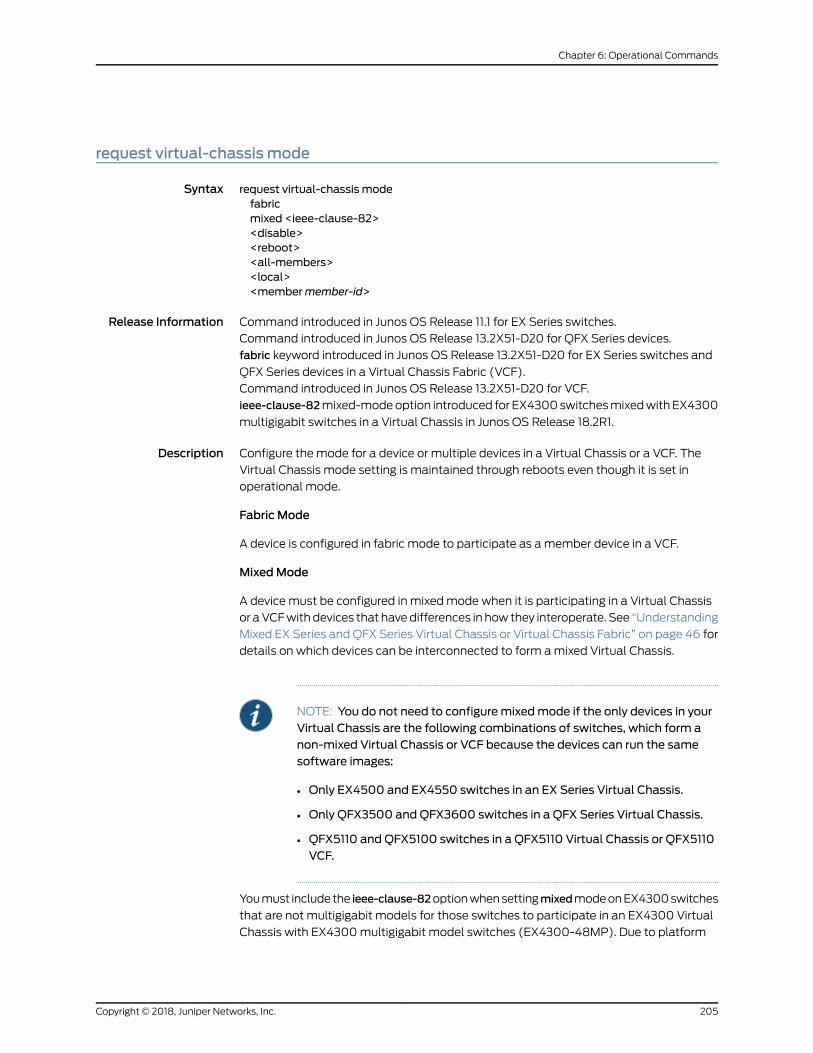
request virtual-chassis mode
Syntax request virtual-chassis modefabricmixed <ieee-clause-82><disable><reboot><all-members><local><membermember-id>
Release Information Command introduced in Junos OS Release 11.1 for EX Series switches.
Command introduced in Junos OS Release 13.2X51-D20 for QFX Series devices.
fabric keyword introduced in Junos OS Release 13.2X51-D20 for EX Series switches and
QFX Series devices in a Virtual Chassis Fabric (VCF).
Command introduced in Junos OS Release 13.2X51-D20 for VCF.
ieee-clause-82mixed-modeoption introduced for EX4300switchesmixedwithEX4300
multigigabit switches in a Virtual Chassis in Junos OS Release 18.2R1.
Description Configure the mode for a device or multiple devices in a Virtual Chassis or a VCF. The
Virtual Chassis mode setting is maintained through reboots even though it is set in
operational mode.
Fabric Mode
A device is configured in fabric mode to participate as amember device in a VCF.
MixedMode
A device must be configured in mixedmode when it is participating in a Virtual Chassis
or aVCFwith devices that havedifferences in how they interoperate. See “Understanding
Mixed EX Series and QFX Series Virtual Chassis or Virtual Chassis Fabric” on page 46 for
details on which devices can be interconnected to form amixed Virtual Chassis.
NOTE: You do not need to configuremixedmode if the only devices in yourVirtual Chassis are the following combinations of switches, which form anon-mixed Virtual Chassis or VCF because the devices can run the samesoftware images:
• Only EX4500 and EX4550 switches in an EX Series Virtual Chassis.
• Only QFX3500 and QFX3600 switches in a QFX Series Virtual Chassis.
• QFX5110 and QFX5100 switches in a QFX5110 Virtual Chassis or QFX5110VCF.
Youmust includethe ieee-clause-82optionwhensettingmixedmodeonEX4300switches
that are not multigigabit models for those switches to participate in an EX4300 Virtual
Chassis with EX4300multigigabit model switches (EX4300-48MP). Due to platform
205Copyright © 2018, Juniper Networks, Inc.
Chapter 6: Operational Commands

differences, this mode is required for other EX4300 switches to properly communicate
with EX4300multigigabit switches.
Do not enable the request virtual-chassismodemixed command for a standalone device
or for amember switch that is intended to remain in a non-mixed Virtual Chassis or VCF.
Enabling this command reduces the maximum scaling numbers for some features on
the switch, Virtual Chassis, or VCF.
BEST PRACTICE: For amixed Virtual Chassis, to avoid potential trafficdisruptionsandconfiguration issues,we recommendconfiguringmixedmodeon your device before cabling it into your Virtual Chassis, and rebooting thedevice to complete this configuration procedure before interconnecting itinto the Virtual Chassis. Similarly, for a VCF, to avoid potential trafficdisruptions and configuration issues, we recommend configuring the fabricand, if applicable, themixedmode settings on your device and rebooting itbefore cabling it into the VCF. You can change the fabric andmixedmodesettingsmanually after a device has been added to a Virtual Chassis or VCF.
If you set only someof the devices in amixedVirtual Chassis or VCF tomixedmode using
this command, the mixed Virtual Chassis or VCFmight not form. If you experience this
issue, enter the request virtual-chassis modemixed all-members command to set the
Virtual Chassismode tomixed for all devices in the Virtual Chassis or VCF. You then need
to reboot the devices that have been set into mixedmode to complete the procedure.
The Virtual Chassis or VCF forms after the devices have rebooted.
NOTE: When you do not use this command to set any of the switches in amixedEX4200andEX4500VirtualChassis tomixedmode, amixedEX4200and EX4500 Virtual Chassis forms with one of the switches assuming themaster role if the switchesare running JunosOSRelease 11.4 or later. All otherswitches in themixed EX4200 and EX4500 Virtual Chassis are placed intothe linecard role. If you experience this behavior, enter the request
virtual-chassis modemixed all-members command to set the Virtual Chassis
mode tomixed for all switches in the Virtual Chassis. You will then need toreboot the switches to complete the procedure. TheVirtual Chassiswill formafter all of the switches have rebooted.
Options Nooptions(default)—Set theVirtualChassismode forallmembersof theVirtualChassisor VCF.
all-members—(Optional) Set the Virtual Chassis mode for all members of the VirtualChassis or VCF.
disable—Disable the Virtual Chassis fabric or mixedmode setting if it was previouslyenabled.
Copyright © 2018, Juniper Networks, Inc.206
Virtual Chassis Feature Guide for Switches

fabric—Set the device into fabric mode so that the device can participate in a VCF.
local—(Optional) Set the Virtual Chassis mode only on themember device where thecommand is issued.
membermember-id—(Optional) Set theVirtual Chassismodeon the specifiedmemberof the Virtual Chassis or VCF.
mixed <ieee-clause-82>—Set the device into mixedmode so that the device canparticipate in amixedVirtual Chassis ormixedVCF. The ieee-clause-82mixed-mode
option is required whenmixing EX4300 switches that are not multigigabit models
with EX4300multigigabit (EX4300-48MP)model switches in an EX4300 Virtual
Chassis.
reboot—After applying themodechangespecifiedby theotheroptions, reboot thedeviceautomatically.
Required PrivilegeLevel
system-control
RelatedDocumentation
UnderstandingMixedEXSeriesandQFXSeriesVirtualChassisorVirtualChassis Fabric
on page 46
•
• ConfiguringaMixedVirtualChassiswithEX4200,EX4500,andEX4550MemberSwitches
(CLI Procedure)
• Verifying the Virtual Chassis Fabric Mode Settings
• Verifying theMember ID, Role, and Neighbor Member Connections of a Virtual Chassis
Member on page 124
List of Sample Output request virtual-chassis modemixed on page 207request virtual-chassis mode fabric mixed reboot on page 207request virtual-chassismodemixed (with IEEEClause 82mode for EX4300 switchesmixedwith EX4300multigigabit switches in a Virtual Chassis) on page 207
Sample Output
request virtual-chassis modemixed
user@switch> request virtual-chassis modemixed
Sample Output
request virtual-chassis mode fabric mixed reboot
user@switch> request virtual-chassis mode fabric mixed reboot
Sample Output
request virtual-chassis modemixed (with IEEE Clause 82mode for EX4300 switchesmixedwith EX4300multigigabit switches in a Virtual Chassis)
user@switch> request virtual-chassis mode ieee-clause-82mixed
207Copyright © 2018, Juniper Networks, Inc.
Chapter 6: Operational Commands

Copyright © 2018, Juniper Networks, Inc.208
Virtual Chassis Feature Guide for Switches

request virtual-chassis recycle
Syntax request virtual-chassis recyclemember-idmember-id
Release Information Command introduced in Junos OS Release 9.0 for EX Series switches.
Command introduced in Junos OS Release 13.2X50-D15 for the QFX Series.
Description Make a previously usedmember ID available for reassignment.
When you remove amember switch from the Virtual Chassis configuration, the master
reserves that member ID. Tomake themember ID available for reassignment, youmust
use this command.
NOTE: Youmust run this command from the Virtual Chassis member in themaster role.
Options member-idmember-id—Specify the member ID that you want to make available forreassignment to a different member.
Required PrivilegeLevel
system-control
RelatedDocumentation
request virtual-chassis renumber on page 210•
• Replacing a Member Switch of a Virtual Chassis Configuration (CLI Procedure) on
page 101
List of Sample Output request virtual-chassis recyclemember-id 3 on page 209request virtual-chassis recyclemember-id 1 on page 209
Sample Output
request virtual-chassis recyclemember-id 3
user@switch> request virtual-chassis recyclemember-id 3
Sample Output
request virtual-chassis recyclemember-id 1
user@external-routing-engine> request virtual-chassis recyclemember-id 1
209Copyright © 2018, Juniper Networks, Inc.
Chapter 6: Operational Commands

request virtual-chassis renumber
Syntax requestvirtual-chassisrenumbermember-idold-member-idnew-member-idnew-member-id
Release Information Command introduced in Junos OS Release 9.0 for EX Series switches.
Command introduced in Junos OS Release 13.2X50-D15 for the QFX Series.
Description Renumber a member of a Virtual Chassis configuration.
NOTE: Youmust run this command from the Virtual Chassis member in themaster role.
Options member-id old-member-id—Specify the ID of the member that you wish to renumber.
new-member-id new-member-id—Specify an unassignedmember ID.
Required PrivilegeLevel
system-control
RelatedDocumentation
request virtual-chassis recycle on page 209•
• Replacing a Member Switch of a Virtual Chassis Configuration (CLI Procedure) on
page 101
List of Sample Output request virtual-chassis renumbermember-id 5 new-member-id 4 on page 210request virtual-chassis renumbermember-id 1 new-member-id 0 on page 210
Sample Output
request virtual-chassis renumbermember-id 5 new-member-id 4
user@switch> request virtual-chassis renumbermember-id 5 new-member-id 4
request virtual-chassis renumbermember-id 1 new-member-id 0
user@external-routing-engine> requestvirtual-chassis renumbermember-id1new-member-id0
Copyright © 2018, Juniper Networks, Inc.210
Virtual Chassis Feature Guide for Switches

request virtual-chassis vc-port
Syntax request virtual-chassis vc-port [set | delete] <fpc-slot fpc-slot> pic-slot pic-slot portport-number <membermember-id>
Release Information Command introduced in Junos OS Release 9.0 for EX Series switches.
Option fpc-slot introduced in Junos OS Release 10.4 for EX Series switches.
Command introduced in Junos OS Release 13.2X50-D15 for the QFX Series.
Command introduced in Junos OSRelease 13.2X51-D20 for Virtual Chassis Fabric (VCF).
Description Enable or disable an optical port as a Virtual Chassis port (VCP).
If youomitmembermember-id, this commanddefaults to enablingor disabling theuplink
VCP or SFP network port configured as a VCP on the switch where the command is
issued.
Youmight experiencea temporary traffic disruption immediately after creatingordeleting
a user-configured VCP in an EX8200 Virtual Chassis.
NOTE: Some EX Series switches have ports that are configured as VCPs bydefault. You do not need to explicitly configure those ports as VCPs to usethem to interconnect the switch into a Virtual Chassis. See “UnderstandingVirtual Chassis Components” on page 34 for details.
Options set—Set a network port as a VCP to convert a network port into a VCP.
delete—Delete the VCP setting on a port to convert a VCP into a network port.
pic-slot pic-slot—Number of the PIC slot for the port on the switch.
port port-number—Number of the port that is to be enabled or disabled as a VCP.
membermember-id—(Optional) Enable or disable the specified VCP on the specifiedmember of the Virtual Chassis or VCF.
Required PrivilegeLevel
system-control
RelatedDocumentation
request virtual-chassis vc-port (dedicated port)•
• show virtual-chassis vc-port on page 258
• show virtual-chassis vc-port statistics on page 276
• clear virtual-chassis vc-port statistics on page 192
• Virtual Chassis Port (VCP) Interface Names in an EX8200 Virtual Chassis
211Copyright © 2018, Juniper Networks, Inc.
Chapter 6: Operational Commands
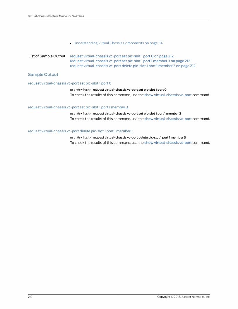
• Understanding Virtual Chassis Components on page 34
List of Sample Output request virtual-chassis vc-port set pic-slot 1 port 0 on page 212request virtual-chassis vc-port set pic-slot 1 port 1 member 3 on page 212request virtual-chassis vc-port delete pic-slot 1 port 1 member 3 on page 212
Sample Output
request virtual-chassis vc-port set pic-slot 1 port 0
user@switch> request virtual-chassis vc-port set pic-slot 1 port 0
To check the results of this command, use the show virtual-chassis vc-port command.
request virtual-chassis vc-port set pic-slot 1 port 1 member 3
user@switch> request virtual-chassis vc-port set pic-slot 1 port 1 member 3
To check the results of this command, use the show virtual-chassis vc-port command.
request virtual-chassis vc-port delete pic-slot 1 port 1 member 3
user@switch> request virtual-chassis vc-port delete pic-slot 1 port 1 member 3
To check the results of this command, use the show virtual-chassis vc-port command.
Copyright © 2018, Juniper Networks, Inc.212
Virtual Chassis Feature Guide for Switches

request virtual-chassis vc-port diagnostics optics
Syntax request virtual-chassis vc-port diagnostics optics
Release Information Command introduced in Junos OS Release 13.2X50-D10 for EX Series switches.
Command introduced in Junos OSRelease 13.2X51-D20 for Virtual Chassis Fabric (VCF).
Description Run a digital optical monitoring (DOM) scan on the optical ports configured as Virtual
Chassis ports (VCPs).
Enter the show virtual-chassis vc-port diagnostics optics command to view the results of
the diagnostic scan.
On certain EX Series switches, the request virtual-chassis vc-port diagnostics optics
commandmust be entered to run a diagnostic scan before you can gather the show
virtual-chassis vc-port diagnostics optics output.
Required PrivilegeLevel
system-control
RelatedDocumentation
show virtual-chassis vc-port diagnostics optics on page 262•
Sample Output
request virtual-chassis vc-port diagnostics optics
user@switch> request virtual-chassis vc-port diagnostics opticsfpc0:--------------------------------------------------------------------------vc-port Diagnostics Optics Done
213Copyright © 2018, Juniper Networks, Inc.
Chapter 6: Operational Commands

show chassis nonstop-upgrade
Syntax show chassis nonstop-upgrade
Release Information Command introduced in Junos OS Release 10.4 for EX Series switches.
Command introduced in Junos OS Release 13.2X50-D15 for the QFX Series.
Description (EX6200 switches, EX8200 switches, EX8200Virtual Chassis, QFX3500andQFX3600
Virtual Chassis, and Virtual Chassis Fabric only) Display the status of the line cards or
Virtual Chassis members in the linecard role after the most recent nonstop software
upgrade (NSSU). This commandmust be issued on themaster Routing Engine.
Required PrivilegeLevel
view
RelatedDocumentation
request system software nonstop-upgrade on page 195•
• Upgrading Software on an EX6200 or EX8200 Standalone Switch Using Nonstop
Software Upgrade (CLI Procedure)
• Upgrading Software on a Virtual Chassis and Mixed Virtual Chassis Using Nonstop
Software Upgrade on page 147
• Upgrading Software on a Virtual Chassis Fabric Using Nonstop Software Upgrade
• Upgrading Software on an EX8200 Virtual Chassis Using Nonstop Software Upgrade
(CLI Procedure)
List of Sample Output show chassis nonstop-upgrade (EX8200 Switch) on page 215show chassis nonstop-upgrade (EX8200 Virtual Chassis) on page 215show chassis nonstop-upgrade (Virtual Chassis Fabric) on page 215
Output Fields Table 10onpage214 lists theoutput fields for theshowchassisnonstop-upgradecommand.
Output fields are listed in the approximate order in which they appear.
Table 10: show chassis nonstop-upgrade Output Fields
Field DescriptionField Name
Line card slot number.Item
State of line card:
• Error—Line card is in an error state.
• Offline—Line card is powered down.
• Online—Line card is online and running.
Status
Reason for the state (if the line card is offline).Reason
Copyright © 2018, Juniper Networks, Inc.214
Virtual Chassis Feature Guide for Switches

Sample Output
show chassis nonstop-upgrade (EX8200 Switch)
user@switch> show chassis nonstop-upgrade Item Status Reason FPC 0 Online FPC 1 Online FPC 2 Online FPC 3 Offline Offlined by CLI command FPC 4 Online FPC 5 Online FPC 6 Online FPC 7 Online
show chassis nonstop-upgrade (EX8200 Virtual Chassis)
user@external-routing-engine> show chassis nonstop-upgrademember0:-------------------------------------------------------------------------- Item Status Reason FPC 0 Online FPC 1 Online FPC 2 Online FPC 5 Online
member1:-------------------------------------------------------------------------- Item Status Reason FPC 0 Online FPC 1 Offline Offlined due to config FPC 2 Online FPC 3 Online FPC 4 Online FPC 5 Online FPC 7 Online
show chassis nonstop-upgrade (Virtual Chassis Fabric)
Item Status Reason FPC 0 Online FPC 1 Online FPC 2 Online FPC 3 Online FPC 4 Online FPC 5 Online
215Copyright © 2018, Juniper Networks, Inc.
Chapter 6: Operational Commands

show virtual-chassis
Syntax show virtual-chassis <status>
Release Information Command introduced in Junos OS Release 9.2 for EX Series switches.
Command introduced in Junos OS Release 13.2X50-D15 for the QFX Series.
Command introduced in Junos OSRelease 13.2X51-D20 for Virtual Chassis Fabric (VCF).
Fabric ID, Fabric Mode, and RouteMode output fields introduced in Junos OS Release
13.2X51-D20.
Alias-Name output field introduced in Junos OS Release 14.1X53-D10.
Description Display information about all members of the Virtual Chassis or VCF.
Options none—Display information about all Virtual Chassis or VCFmember devices.
status—Same output as for show virtual-chassiswithout any options.
Required PrivilegeLevel
view
RelatedDocumentation
show virtual-chassis active-topology on page 222•
• show virtual-chassis protocol adjacency on page 237
• show virtual-chassis vc-path on page 254
• UnderstandingMixedEXSeriesandQFXSeriesVirtualChassisorVirtualChassis Fabric
on page 46
• Monitoring the Virtual Chassis Status and Statistics on EX Series Virtual Chassis
List of Sample Output show virtual-chassis (EX2300multigigabit model—EX2300-24MP andEX2300-48MP—Virtual Chassis) on page 218show virtual-chassis (EX4200 Virtual Chassis) on page 218show virtual-chassis (Mixed EX4300multigigabit model—EX4300-48MP—VirtualChassis) on page 219show virtual-chassis (EX8200 Virtual Chassis) on page 219show virtual-chassis (QFX5110 Virtual Chassis) on page 220show virtual-chassis (QFX5200 Virtual Chassis) on page 220show virtual-chassis (QFX5100 Virtual Chassis Fabric) on page 220
Output Fields Table 11 on page 216 lists the output fields for the showvirtual-chassis command. Output
fields are listed in the approximate order in which they appear.
Table 11: show virtual-chassis Output Fields
Field DescriptionField Name
(VCF only) Assigned ID used to identify the VCF.Fabric ID
Copyright © 2018, Juniper Networks, Inc.216
Virtual Chassis Feature Guide for Switches

Table 11: show virtual-chassis Output Fields (continued)
Field DescriptionField Name
(VCF only) Mode of the VCF: Enabled, Disabled, or Mixed.Fabric Mode
Assigned ID that applies to the entire Virtual Chassis or VCF.Virtual Chassis ID
Mode of the Virtual Chassis or VCF. This field indicates support for the Virtual Chassisfeature and, if a Virtual Chassis is configured, if it is a mixed or homogenous VirtualChassis. Values can be:
• Enabled—The platform supports the Virtual Chassis feature. If a Virtual Chassis iscurrently configured, this is a homogenous Virtual Chassis (all members are thesame type of switch).
• Disabled—The switch does not support the Virtual Chassis feature.
NOTE: Switches that support the Virtual Chassis feature do not display this value.Even if a Virtual Chassis is not currently configured, those switches display Enabledin this field.
• Mixed—The platform supports the Virtual Chassis feature, and is configured as amixedmode Virtual Chassis (members consist of more than one type of switch).
Virtual ChassisMode
Assignedmember ID and FPC:
• On all EX Series Virtual Chassis except EX8200 Virtual Chassis, and on a VCF, theFPC number refers to the member ID assigned to the switch.
• OnEX8200VirtualChassis,member IDsarenumbered0through9.TheFPCnumberindicates the slot numberof the linecardwithin theVirtualChassis. TheFPCnumberonmember 0 is always 0 through 15. The FPC number onmember 1 is always 16through 31. The FPC number onmember 2 is always 32 through 47; and so on forthe members.
Member ID
For a nonprovisioned configuration:
• Prsnt for a member that is currently connected to the Virtual Chassis or VCFconfiguration.
• NotPrsnt for a member ID that has been assigned but is not currently connected.
For a preprovisioned configuration:
• Prsnt for a member that is specified in the preprovisioned configuration file and iscurrently connected to the Virtual Chassis or VCF.
• Unprvsnd for a member that is interconnected with the Virtual Chassis or VCFconfiguration but is not specified in the preprovisioned configuration file.
Status
Serial number of the member device.Serial No
The user-configured alias of the member device.
The Alias-Name field appears only if an alias has been configured for at least onedevice in the Virtual Chassis or VCF. Aliases are configured using the alias-namestatement in the [edit virtual-chassis aliases serial-number serial-number] hierarchy.
Alias-Name
Model number of the member device.Model
217Copyright © 2018, Juniper Networks, Inc.
Chapter 6: Operational Commands

Table 11: show virtual-chassis Output Fields (continued)
Field DescriptionField Name
Mastership priority value of the member device.MastershipPriorityorMstr prio
Role of the member device: master, backup, or linecard.
An asterisk ( * ) following the Role denotes the member device on which the showvirtual-chassis <status> command was issued.
Role
Mixedmode configuration status:
• Y for a member device configured in mixedmode.
• N for a member device not configured in mixedmode.
• NA for a member device that cannot be configured in mixedmode.
MixedMode
The route mode of the member device: fabric (F) or Virtual Chassis (V).RouteMode
Location of the member device.
If this field is empty, the location field was not set for the device.
Location
Member IDof theneighbormember towhich thismember’sVirtualChassisport (VCP)is connected, and the VCP interface name.
Neighbor List IDand Interface
Sample Output
show virtual-chassis (EX2300multigigabit model—EX2300-24MP and EX2300-48MP—Virtual Chassis)
user@switch> show virtual-chassis
Virtual Chassis ID: abcd.ef12.3456 Virtual Chassis Mode: Enabled Mstr Mixed Route Neighbor ListMember ID Status Serial No Model prio Role Mode Mode ID Interface0 (FPC 0) Prsnt XP3117380018 ex2300-24mp 128 Backup N VC 3 vcp-255/1/0 1 vcp-255/1/21 (FPC 1) Prsnt XN3117380031 ex2300-48mp 128 Master* N VC 2 vcp-255/1/4 0 vcp-255/1/12 (FPC 2) Prsnt XP3117380019 ex2300-24mp 128 Linecard N VC 3 vcp-255/1/0 1 vcp-255/1/13 (FPC 3) Prsnt XP3717410002 ex2300-48mp 128 Linecard N VC 0 vcp-255/1/4 2 vcp-255/1/5
show virtual-chassis (EX4200 Virtual Chassis)
user@switch> show virtual-chassis
Virtual Chassis ID: 00ab.cdef.1234Virtual Chassis Mode: Enabled Mastership Mixed Neighbor ListMember ID Status Serial No Model priority Role Mode ID Interface0 (FPC 0) Prsnt AK0207360276 ex4200-24t 249 Master* N 8 vcp-0 1 vcp-1 1 (FPC 1) Prsnt AK0207360281 ex4200-24t 248 Backup N 0 vcp-0
Copyright © 2018, Juniper Networks, Inc.218
Virtual Chassis Feature Guide for Switches

2 vcp-1 2 (FPC 2) Prsnt AJ0207391130 ex4200-48p 247 Linecard N 1 vcp-0 3 vcp-1 3 (FPC 3) Prsnt AK0207360280 ex4200-24t 246 Linecard N 2 vcp-0 4 vcp-1 4 (FPC 4) Prsnt AJ0207391113 ex4200-48p 245 Linecard N 3 vcp-0 5 vcp-1 5 (FPC 5) Prsnt BP0207452204 ex4200-48t 244 Linecard N 4 vcp-0 6 vcp-1 6 (FPC 6) Prsnt BP0207452222 ex4200-48t 243 Linecard N 5 vcp-0 7 vcp-1 7 (FPC 7) Prsnt BR0207432028 ex4200-24f 242 Linecard N 6 vcp-0 8 vcp-1 8 (FPC 8) Prsnt BR0207431996 ex4200-24f 241 Linecard N 7 vcp-0 0 vcp-1 Member ID for next new member: 9 (FPC 9)
show virtual-chassis (Mixed EX4300multigigabit model—EX4300-48MP—Virtual Chassis)
user@switch> show virtual-chassis
Preprovisioned Virtual ChassisVirtual Chassis ID: abcd.ef00.1234Virtual Chassis Mode: Mixed Mstr Mixed Route Neighbor ListMember ID Status Serial No Model prio Role Mode Mode ID Interface0 (FPC 0) Prsnt XR3617480028 ex4300-48mp 129 Master* Y VC 1 vcp-255/1/0 3 vcp-255/1/31 (FPC 1) Prsnt XR3617480029 ex4300-48mp 129 Backup Y VC 0 vcp-255/1/1 2 vcp-255/1/32 (FPC 2) Prsnt XR3617480001 ex4300-48mp 0 Linecard Y VC 3 vcp-255/1/1 1 vcp-255/1/33 (FPC 3) Prsnt PE3715471074 ex4300-48t 0 Linecard Y VC 0 vcp-255/1/0 2 vcp-255/1/2
show virtual-chassis (EX8200 Virtual Chassis)
user@external-routing-engine> show virtual-chassis
Virtual Chassis ID: cdcd.1212.efefVirtual Chassis Mode: Enabled Mastership Neighbor ListMember ID Status Serial No Model priority Role ID Interface0 (FPC 0-15) Prsnt BA0908380001 ex8216 0 Linecard 8 vcp-0/0 8 vcp-0/1 1 vcp-4/0/41 (FPC 16-31) Prsnt BT0909411634 ex8208 0 Linecard 8 vcp-0/0 0 vcp-3/0/48 (FPC 128-143) Prsnt 062009000021 ex-xre 128 Master 9 vcp-1/0 1 vcp-1/2 9 vcp-1/3 0 vcp-2/0 9 vcp-2/1 0 vcp-1/19 (FPC 144-159) Prsnt 062009000022 ex-xre 128 Backup* 8 vcp-1/0 8 vcp-1/2 8 vcp-1/3 8 vcp-1/3
219Copyright © 2018, Juniper Networks, Inc.
Chapter 6: Operational Commands

show virtual-chassis (QFX5110 Virtual Chassis)
user@switch> show virtual-chassis
Preprovisioned Virtual ChassisVirtual Chassis ID: abab.1212.cdcdVirtual Chassis Mode: Enabled Mstr Mixed Route Neighbor ListMember ID Status Serial No Model prio Role Mode Mode ID Interface0 (FPC 0) Prsnt WT3116360038 qfx5110-32q 129 Backup Y VC 9 vcp-255/0/12 1 vcp-255/0/161 (FPC 1) Prsnt WT3116360041 qfx5110-32q 129 Master* Y VC 2 vcp-255/0/16 0 vcp-255/0/172 (FPC 2) Prsnt WT3116360051 qfx5110-32q 0 Linecard Y VC 3 vcp-255/0/11 1 vcp-255/0/143 (FPC 3) Prsnt WT3116360055 qfx5110-32q 0 Linecard Y VC 4 vcp-255/0/14 2 vcp-255/0/314 (FPC 4) Prsnt WT3116360056 qfx5110-32q 0 Linecard Y VC 5 vcp-255/0/10 3 vcp-255/0/55 (FPC 5) Prsnt TB3716340058 qfx5100e-24q-2p 0 Linecard Y VC 6 vcp-255/0/12 4 vcp-255/0/206 (FPC 6) Prsnt WS3715500018 qfx5110-48s-4c 0 Linecard Y VC 7 vcp-255/0/10 5 vcp-255/0/497 (FPC 7) Prsnt TA3714110007 qfx5100e-48s-6q 0 Linecard Y VC 6 vcp-255/0/18 8 vcp-255/0/318 (FPC 8) Prsnt WS3715500022 qfx5110-48s-4c 0 Linecard Y VC 7 vcp-255/0/21 9 vcp-255/0/499 (FPC 9) Prsnt WT3116360061 qfx5110-32q 0 Linecard Y VC 8 vcp-255/0/13 0 vcp-255/0/17
show virtual-chassis (QFX5200 Virtual Chassis)
user@switch> show virtual-chassis
Virtual Chassis ID: abab.1212.cdcdVirtual Chassis Mode: Enabled Mixed Route Neighbor ListMember ID Status Serial No Model prio Role Mode Mode ID Interface0 (FPC 0) Prsnt XY0123456789 qfx5200-32c-r 128 Master* N VC 1 vcp-255/0/19 2 vcp-255/0/261 (FPC 1) Prsnt XY0123456780 qfx5200-32c-r 128 Linecard N VC 0 vcp-255/0/20 2 vcp-255/0/162 (FPC 2) Prsnt YZ0123456789 qfx5200-32c-32q 128 Backup N VC 0 vcp-255/0/15 1 vcp-255/0/18
show virtual-chassis (QFX5100 Virtual Chassis Fabric)
user@switch> show virtual-chassis
Preprovisioned Virtual Chassis FabricFabric ID: 0123.abcd.4567Fabric Mode: Enabled Mstr Mixed Route Neighbor ListMember ID Status Serial No Model prio Role Mode Mode ID Interface0 (FPC 0) Prsnt AB3112430001 qfx5100-48s 129 Master* N F 3 vcp-255/1/0 2 vcp-255/1/1 4 vcp-255/1/2 4 vcp-255/1/31 (FPC 1) Prsnt AB3112230001 qfx5100-48s 129 Backup N F 3 vcp-255/1/0
Copyright © 2018, Juniper Networks, Inc.220
Virtual Chassis Feature Guide for Switches

2 vcp-255/1/1 4 vcp-255/1/2 4 vcp-255/1/32 (FPC 2) Prsnt AB3112460011 qfx5100-48s 0 Linecard N F 1 vcp-255/1/0 0 vcp-255/1/13 (FPC 3) Prsnt AB3112460011 qfx5100-48s 0 Linecard N F 1 vcp-255/1/0 0 vcp-255/1/14 (FPC 4) Prsnt AB3112430011 qfx5100-48s 0 Linecard N F 1 vcp-255/1/0 0 vcp-255/1/1
221Copyright © 2018, Juniper Networks, Inc.
Chapter 6: Operational Commands

show virtual-chassis active-topology
Syntax show virtual-chassis active-topology<all-members><local><membermember-id>
Release Information Command introduced in Junos OS Release 9.0 for EX Series switches.
Command introduced in Junos OS Release 13.2X50-D15 for the QFX Series.
Command introduced in Junos OSRelease 13.2X51-D20 for Virtual Chassis Fabric (VCF).
Description Display the active topology of the Virtual Chassis or VCF with next-hop reachability
information.
Options none—Display the active topology of themember switch where the command is issued.
all-members—(Optional) Display the active topology of all members of the VirtualChassis or VCF.
local—(Optional) Display the active topology of the switch or external Routing Engineon which this command is entered.
membermember-id—(Optional) Display the active topology of the specified memberof the Virtual Chassis or VCF.
Required PrivilegeLevel
view
RelatedDocumentation
Monitoring the Virtual Chassis Status and Statistics on EX Series Virtual Chassis•
• Understanding EX Series Virtual Chassis Configuration on page 59
List of Sample Output show virtual-chassis active-topology (EX4200 Virtual Chassis) on page 223show virtual-chassis active-topology (EX8200 Virtual Chassis) on page 223show virtual-chassis active-topology (Virtual Chassis Fabric) on page 224
Output Fields Table 12 on page 222 lists the output fields for the show virtual-chassis active-topology
command. Output fields are listed in the approximate order in which they appear.
Table 12: show virtual-chassis active-topology Output Fields
Field DescriptionField Name
Specifies the member ID of the destination.Destination ID
Specifies themember ID andVirtual Chassis port (VCP) of the next hop towhichpackets for the destination ID are forwarded.
The next hop can bemore than one device in a VCF.
Next-hop
Copyright © 2018, Juniper Networks, Inc.222
Virtual Chassis Feature Guide for Switches

Sample Output
show virtual-chassis active-topology (EX4200 Virtual Chassis)
user@switch> show virtual-chassis active-topology 1 1(vcp-1)
2 1(vcp-1)
3 1(vcp-1)
4 1(vcp-1)
5 8(vcp-0) 1(vcp-1)
6 8(vcp-0)
7 8(vcp-0)
8 8(vcp-0)
show virtual-chassis active-topology (EX8200 Virtual Chassis)
user@external-routing-engine> show virtual-chassis active-topology member0:-------------------------------------------------------------------------- Destination ID Next-hop
1 1(vcp-4/0/4.32768)
8 8(vcp-0/0.32768)
9 8(vcp-0/0.32768)
member1:-------------------------------------------------------------------------- Destination ID Next-hop
0 0(vcp-3/0/4.32768)
8 8(vcp-0/0.32768)
9 8(vcp-0/0.32768)
223Copyright © 2018, Juniper Networks, Inc.
Chapter 6: Operational Commands

member8:-------------------------------------------------------------------------- Destination ID Next-hop
0 0(vcp-1/1.32768)
1 1(vcp-1/2.32768)
9 9(vcp-2/1.32768)
member9:-------------------------------------------------------------------------- Destination ID Next-hop
0 8(vcp-1/2.32768)
1 8(vcp-1/2.32768)
8 8(vcp-1/2.32768)
show virtual-chassis active-topology (Virtual Chassis Fabric)
user@device> show virtual-chassis active-topologyfpc0:-------------------------------------------------------------------------- Destination ID Next-hop
1 4(vcp-255/0/2.32768) 5(vcp-255/0/3.32768) 6(vcp-255/0/1.32768)
2 4(vcp-255/0/2.32768) 5(vcp-255/0/3.32768) 6(vcp-255/0/1.32768)
3 4(vcp-255/0/2.32768) 5(vcp-255/0/3.32768) 6(vcp-255/0/1.32768)
4 4(vcp-255/0/2.32768)
5 5(vcp-255/0/3.32768)
6 6(vcp-255/0/1.32768)
fpc1:-------------------------------------------------------------------------- Destination ID Next-hop
0 4(vcp-255/0/2.32768) 5(vcp-255/0/3.32768) 6(vcp-255/0/1.32768)
2 4(vcp-255/0/2.32768) 5(vcp-255/0/3.32768) 6(vcp-255/0/1.32768)
3 4(vcp-255/0/2.32768) 5(vcp-255/0/3.32768) 6(vcp-255/0/1.32768)
4 4(vcp-255/0/2.32768)
5 5(vcp-255/0/3.32768)
6 6(vcp-255/0/1.32768)
Copyright © 2018, Juniper Networks, Inc.224
Virtual Chassis Feature Guide for Switches

fpc2:-------------------------------------------------------------------------- Destination ID Next-hop
0 4(vcp-255/0/2.32768) 5(vcp-255/0/3.32768) 6(vcp-255/0/1.32768)
1 4(vcp-255/0/2.32768) 5(vcp-255/0/3.32768) 6(vcp-255/0/1.32768)
3 4(vcp-255/0/2.32768) 5(vcp-255/0/3.32768) 6(vcp-255/0/1.32768)
4 4(vcp-255/0/2.32768)
5 5(vcp-255/0/3.32768)
6 6(vcp-255/0/1.32768)
fpc3:-------------------------------------------------------------------------- Destination ID Next-hop
0 4(vcp-255/0/2.32768) 5(vcp-255/0/3.32768) 6(vcp-255/0/1.32768)
1 4(vcp-255/0/2.32768) 5(vcp-255/0/3.32768) 6(vcp-255/0/1.32768)
2 4(vcp-255/0/2.32768) 5(vcp-255/0/3.32768) 6(vcp-255/0/1.32768)
4 4(vcp-255/0/2.32768)
5 5(vcp-255/0/3.32768)
6 6(vcp-255/0/1.32768)
fpc4:-------------------------------------------------------------------------- Destination ID Next-hop
0 0(vcp-255/0/48.32768)
1 1(vcp-255/0/49.32768)
2 2(vcp-255/0/50.32768)
3 3(vcp-255/0/51.32768)
5 3(vcp-255/0/51.32768) 2(vcp-255/0/50.32768) 0(vcp-255/0/48.32768) 1(vcp-255/0/49.32768)
6 3(vcp-255/0/51.32768) 2(vcp-255/0/50.32768) 0(vcp-255/0/48.32768) 1(vcp-255/0/49.32768)
fpc5:-------------------------------------------------------------------------- Destination ID Next-hop
0 0(vcp-255/0/48.32768)
225Copyright © 2018, Juniper Networks, Inc.
Chapter 6: Operational Commands

1 1(vcp-255/0/49.32768)
2 2(vcp-255/0/50.32768)
3 3(vcp-255/0/51.32768)
4 3(vcp-255/0/51.32768) 2(vcp-255/0/50.32768) 0(vcp-255/0/48.32768) 1(vcp-255/0/49.32768)
6 3(vcp-255/0/51.32768) 2(vcp-255/0/50.32768) 0(vcp-255/0/48.32768) 1(vcp-255/0/49.32768)
fpc6:-------------------------------------------------------------------------- Destination ID Next-hop
0 0(vcp-255/0/0.32768)
1 1(vcp-255/0/1.32768)
2 2(vcp-255/0/2.32768)
3 3(vcp-255/0/3.32768)
4 3(vcp-255/0/3.32768) 2(vcp-255/0/2.32768) 0(vcp-255/0/0.32768) 1(vcp-255/0/1.32768)
5 3(vcp-255/0/3.32768) 2(vcp-255/0/2.32768) 0(vcp-255/0/0.32768) 1(vcp-255/0/1.32768)
Copyright © 2018, Juniper Networks, Inc.226
Virtual Chassis Feature Guide for Switches

show virtual-chassis device-topology
Syntax show virtual-chassis device-topology<all-members><local><membermember-id>
Release Information Command introduced in Junos OS Release 10.4 for EX Series switches.
Command introduced in Junos OS Release 13.2X50-D15 for the QFX Series.
Command introduced in Junos OSRelease 13.2X51-D20 for Virtual Chassis Fabric (VCF).
Description Display the device topology—themember and system IDs, the VCP numbers, and device
status—for all hardware devices in the Virtual Chassis or VCF.
Options none—Display the device topology for all members of the Virtual Chassis or VCF.
all-members—(Optional) Display the device topology for all members of the VirtualChassis or VCF.
local—(Optional) Display the device topology for the switch or external Routing Engineon which this command is entered.
membermember-id—(Optional) Display the device topology for the specified memberof the Virtual Chassis or VCF.
Required PrivilegeLevel
clear
RelatedDocumentation
Understanding Virtual Chassis Port Link Aggregation on page 57•
• Understanding EX8200 Virtual Chassis Topologies
Output Fields Table 13 on page 227 lists the output fields for the show virtual-chassis device-topology
command. Output fields are listed in the approximate order in which they appear.
Table 13: show virtual-chassis device-topology Output Fields
Field DescriptionField Name
Assignedmember ID.Member
Assigned device ID.
For an EX8200 Virtual Chassis, the member ID and the device ID are alwaysidentical.
Device
227Copyright © 2018, Juniper Networks, Inc.
Chapter 6: Operational Commands

Table 13: show virtual-chassis device-topology Output Fields (continued)
Field DescriptionField Name
The status of the device within the Virtual Chassis or VCF. Outputs include:
• Prsnt—Device is currently connected toandparticipating in theVirtualChassisor VCF.
• NotPrsnt—Device is assigned but is not currently connected.
Status
System ID of the device.
The system ID of the device is the device’s MAC address.
System ID
Assignedmember ID of the neighbor device.Member(NeighborList)
Assigned device ID of the neighbor device.
For an EX8200 Virtual Chassis, the member ID and the device ID are alwaysidentical.
Device (NeighborList)
The interface connecting the device to the neighbor.Interface(Neighbor List)
Sample Output
show virtual-chassis device-topology
user@switch> show virtual-chassis device-topologymember0:-------------------------------------------------------------------------- Neighbor ListMember Device Status System ID Member Device Interface 0 0 Prsnt 0021.59f7.d000 8 8 vcp-0/0 1 1 vcp-4/0/1 1 1 Prsnt 0026.888d.6800 8 8 vcp-0/0 9 9 vcp-0/1 0 0 vcp-3/0/4 8 8 Prsnt 0000.4a75.9b7c 9 9 vcp-1/0 0 0 vcp-1/1 1 1 vcp-1/2 9 9 Prsnt 0000.73e9.9a57 8 8 vcp-1/0 1 1 vcp-1/1
member1:-------------------------------------------------------------------------- Neighbor ListMember Device Status System ID Member Device Interface 0 0 Prsnt 0021.59f7.d000 8 8 vcp-0/0 1 1 vcp-4/0/1 1 1 Prsnt 0026.888d.6800 8 8 vcp-0/0 9 9 vcp-0/1 0 0 vcp-3/0/4 8 8 Prsnt 0000.4a75.9b7c 9 9 vcp-1/0 0 0 vcp-1/1 1 1 vcp-1/2
Copyright © 2018, Juniper Networks, Inc.228
Virtual Chassis Feature Guide for Switches
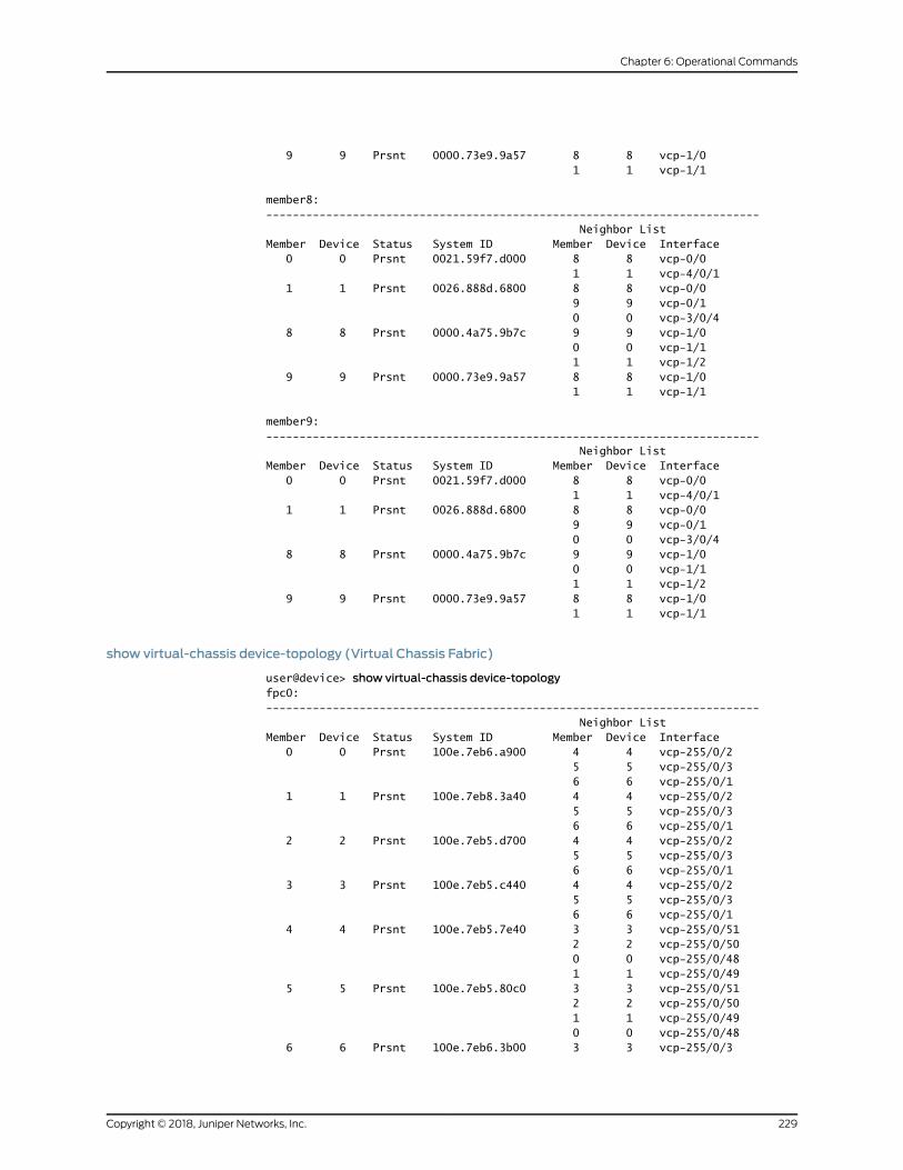
9 9 Prsnt 0000.73e9.9a57 8 8 vcp-1/0 1 1 vcp-1/1
member8:-------------------------------------------------------------------------- Neighbor ListMember Device Status System ID Member Device Interface 0 0 Prsnt 0021.59f7.d000 8 8 vcp-0/0 1 1 vcp-4/0/1 1 1 Prsnt 0026.888d.6800 8 8 vcp-0/0 9 9 vcp-0/1 0 0 vcp-3/0/4 8 8 Prsnt 0000.4a75.9b7c 9 9 vcp-1/0 0 0 vcp-1/1 1 1 vcp-1/2 9 9 Prsnt 0000.73e9.9a57 8 8 vcp-1/0 1 1 vcp-1/1
member9:-------------------------------------------------------------------------- Neighbor ListMember Device Status System ID Member Device Interface 0 0 Prsnt 0021.59f7.d000 8 8 vcp-0/0 1 1 vcp-4/0/1 1 1 Prsnt 0026.888d.6800 8 8 vcp-0/0 9 9 vcp-0/1 0 0 vcp-3/0/4 8 8 Prsnt 0000.4a75.9b7c 9 9 vcp-1/0 0 0 vcp-1/1 1 1 vcp-1/2 9 9 Prsnt 0000.73e9.9a57 8 8 vcp-1/0 1 1 vcp-1/1
show virtual-chassis device-topology (Virtual Chassis Fabric)
user@device> show virtual-chassis device-topologyfpc0:-------------------------------------------------------------------------- Neighbor ListMember Device Status System ID Member Device Interface 0 0 Prsnt 100e.7eb6.a900 4 4 vcp-255/0/2 5 5 vcp-255/0/3 6 6 vcp-255/0/1 1 1 Prsnt 100e.7eb8.3a40 4 4 vcp-255/0/2 5 5 vcp-255/0/3 6 6 vcp-255/0/1 2 2 Prsnt 100e.7eb5.d700 4 4 vcp-255/0/2 5 5 vcp-255/0/3 6 6 vcp-255/0/1 3 3 Prsnt 100e.7eb5.c440 4 4 vcp-255/0/2 5 5 vcp-255/0/3 6 6 vcp-255/0/1 4 4 Prsnt 100e.7eb5.7e40 3 3 vcp-255/0/51 2 2 vcp-255/0/50 0 0 vcp-255/0/48 1 1 vcp-255/0/49 5 5 Prsnt 100e.7eb5.80c0 3 3 vcp-255/0/51 2 2 vcp-255/0/50 1 1 vcp-255/0/49 0 0 vcp-255/0/48 6 6 Prsnt 100e.7eb6.3b00 3 3 vcp-255/0/3
229Copyright © 2018, Juniper Networks, Inc.
Chapter 6: Operational Commands
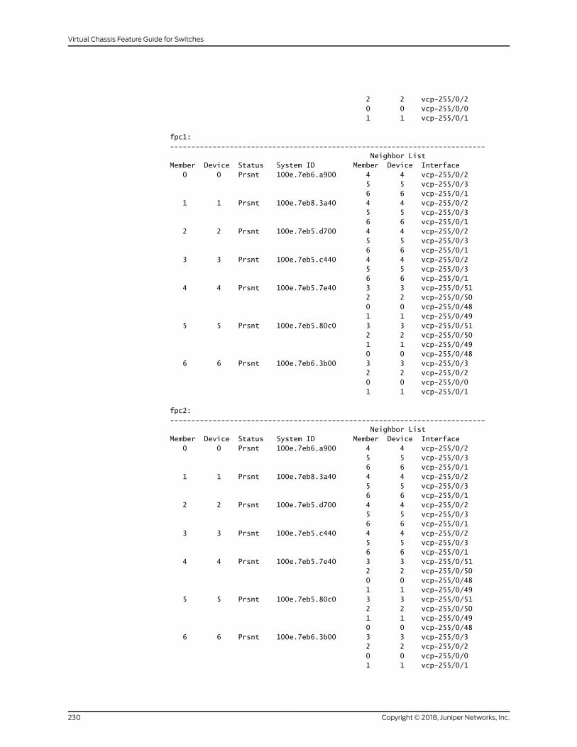
2 2 vcp-255/0/2 0 0 vcp-255/0/0 1 1 vcp-255/0/1
fpc1:-------------------------------------------------------------------------- Neighbor ListMember Device Status System ID Member Device Interface 0 0 Prsnt 100e.7eb6.a900 4 4 vcp-255/0/2 5 5 vcp-255/0/3 6 6 vcp-255/0/1 1 1 Prsnt 100e.7eb8.3a40 4 4 vcp-255/0/2 5 5 vcp-255/0/3 6 6 vcp-255/0/1 2 2 Prsnt 100e.7eb5.d700 4 4 vcp-255/0/2 5 5 vcp-255/0/3 6 6 vcp-255/0/1 3 3 Prsnt 100e.7eb5.c440 4 4 vcp-255/0/2 5 5 vcp-255/0/3 6 6 vcp-255/0/1 4 4 Prsnt 100e.7eb5.7e40 3 3 vcp-255/0/51 2 2 vcp-255/0/50 0 0 vcp-255/0/48 1 1 vcp-255/0/49 5 5 Prsnt 100e.7eb5.80c0 3 3 vcp-255/0/51 2 2 vcp-255/0/50 1 1 vcp-255/0/49 0 0 vcp-255/0/48 6 6 Prsnt 100e.7eb6.3b00 3 3 vcp-255/0/3 2 2 vcp-255/0/2 0 0 vcp-255/0/0 1 1 vcp-255/0/1
fpc2:-------------------------------------------------------------------------- Neighbor ListMember Device Status System ID Member Device Interface 0 0 Prsnt 100e.7eb6.a900 4 4 vcp-255/0/2 5 5 vcp-255/0/3 6 6 vcp-255/0/1 1 1 Prsnt 100e.7eb8.3a40 4 4 vcp-255/0/2 5 5 vcp-255/0/3 6 6 vcp-255/0/1 2 2 Prsnt 100e.7eb5.d700 4 4 vcp-255/0/2 5 5 vcp-255/0/3 6 6 vcp-255/0/1 3 3 Prsnt 100e.7eb5.c440 4 4 vcp-255/0/2 5 5 vcp-255/0/3 6 6 vcp-255/0/1 4 4 Prsnt 100e.7eb5.7e40 3 3 vcp-255/0/51 2 2 vcp-255/0/50 0 0 vcp-255/0/48 1 1 vcp-255/0/49 5 5 Prsnt 100e.7eb5.80c0 3 3 vcp-255/0/51 2 2 vcp-255/0/50 1 1 vcp-255/0/49 0 0 vcp-255/0/48 6 6 Prsnt 100e.7eb6.3b00 3 3 vcp-255/0/3 2 2 vcp-255/0/2 0 0 vcp-255/0/0 1 1 vcp-255/0/1
Copyright © 2018, Juniper Networks, Inc.230
Virtual Chassis Feature Guide for Switches

fpc3:-------------------------------------------------------------------------- Neighbor ListMember Device Status System ID Member Device Interface 0 0 Prsnt 100e.7eb6.a900 4 4 vcp-255/0/2 5 5 vcp-255/0/3 6 6 vcp-255/0/1 1 1 Prsnt 100e.7eb8.3a40 4 4 vcp-255/0/2 5 5 vcp-255/0/3 6 6 vcp-255/0/1 2 2 Prsnt 100e.7eb5.d700 4 4 vcp-255/0/2 5 5 vcp-255/0/3 6 6 vcp-255/0/1 3 3 Prsnt 100e.7eb5.c440 4 4 vcp-255/0/2 5 5 vcp-255/0/3 6 6 vcp-255/0/1 4 4 Prsnt 100e.7eb5.7e40 3 3 vcp-255/0/51 2 2 vcp-255/0/50 0 0 vcp-255/0/48 1 1 vcp-255/0/49 5 5 Prsnt 100e.7eb5.80c0 3 3 vcp-255/0/51 2 2 vcp-255/0/50 1 1 vcp-255/0/49 0 0 vcp-255/0/48 6 6 Prsnt 100e.7eb6.3b00 3 3 vcp-255/0/3 2 2 vcp-255/0/2 0 0 vcp-255/0/0 1 1 vcp-255/0/1
fpc4:-------------------------------------------------------------------------- Neighbor ListMember Device Status System ID Member Device Interface 0 0 Prsnt 100e.7eb6.a900 4 4 vcp-255/0/2 5 5 vcp-255/0/3 6 6 vcp-255/0/1 1 1 Prsnt 100e.7eb8.3a40 4 4 vcp-255/0/2 5 5 vcp-255/0/3 6 6 vcp-255/0/1 2 2 Prsnt 100e.7eb5.d700 4 4 vcp-255/0/2 5 5 vcp-255/0/3 6 6 vcp-255/0/1 3 3 Prsnt 100e.7eb5.c440 4 4 vcp-255/0/2 5 5 vcp-255/0/3 6 6 vcp-255/0/1 4 4 Prsnt 100e.7eb5.7e40 3 3 vcp-255/0/51 2 2 vcp-255/0/50 0 0 vcp-255/0/48 1 1 vcp-255/0/49 5 5 Prsnt 100e.7eb5.80c0 3 3 vcp-255/0/51 2 2 vcp-255/0/50 1 1 vcp-255/0/49 0 0 vcp-255/0/48 6 6 Prsnt 100e.7eb6.3b00 3 3 vcp-255/0/3 2 2 vcp-255/0/2 0 0 vcp-255/0/0 1 1 vcp-255/0/1
fpc5:--------------------------------------------------------------------------
231Copyright © 2018, Juniper Networks, Inc.
Chapter 6: Operational Commands

Neighbor ListMember Device Status System ID Member Device Interface 0 0 Prsnt 100e.7eb6.a900 4 4 vcp-255/0/2 5 5 vcp-255/0/3 6 6 vcp-255/0/1 1 1 Prsnt 100e.7eb8.3a40 4 4 vcp-255/0/2 5 5 vcp-255/0/3 6 6 vcp-255/0/1 2 2 Prsnt 100e.7eb5.d700 4 4 vcp-255/0/2 5 5 vcp-255/0/3 6 6 vcp-255/0/1 3 3 Prsnt 100e.7eb5.c440 4 4 vcp-255/0/2 5 5 vcp-255/0/3 6 6 vcp-255/0/1 4 4 Prsnt 100e.7eb5.7e40 3 3 vcp-255/0/51 2 2 vcp-255/0/50 0 0 vcp-255/0/48 1 1 vcp-255/0/49 5 5 Prsnt 100e.7eb5.80c0 3 3 vcp-255/0/51 2 2 vcp-255/0/50 1 1 vcp-255/0/49 0 0 vcp-255/0/48 6 6 Prsnt 100e.7eb6.3b00 3 3 vcp-255/0/3 2 2 vcp-255/0/2 0 0 vcp-255/0/0 1 1 vcp-255/0/1
fpc6:-------------------------------------------------------------------------- Neighbor ListMember Device Status System ID Member Device Interface 0 0 Prsnt 100e.7eb6.a900 4 4 vcp-255/0/2 5 5 vcp-255/0/3 6 6 vcp-255/0/1 1 1 Prsnt 100e.7eb8.3a40 4 4 vcp-255/0/2 5 5 vcp-255/0/3 6 6 vcp-255/0/1 2 2 Prsnt 100e.7eb5.d700 4 4 vcp-255/0/2 5 5 vcp-255/0/3 6 6 vcp-255/0/1 3 3 Prsnt 100e.7eb5.c440 4 4 vcp-255/0/2 5 5 vcp-255/0/3 6 6 vcp-255/0/1 4 4 Prsnt 100e.7eb5.7e40 3 3 vcp-255/0/51 2 2 vcp-255/0/50 0 0 vcp-255/0/48 1 1 vcp-255/0/49 5 5 Prsnt 100e.7eb5.80c0 3 3 vcp-255/0/51 2 2 vcp-255/0/50 1 1 vcp-255/0/49 0 0 vcp-255/0/48 6 6 Prsnt 100e.7eb6.3b00 3 3 vcp-255/0/3 2 2 vcp-255/0/2 0 0 vcp-255/0/0 1 1 vcp-255/0/1
Copyright © 2018, Juniper Networks, Inc.232
Virtual Chassis Feature Guide for Switches
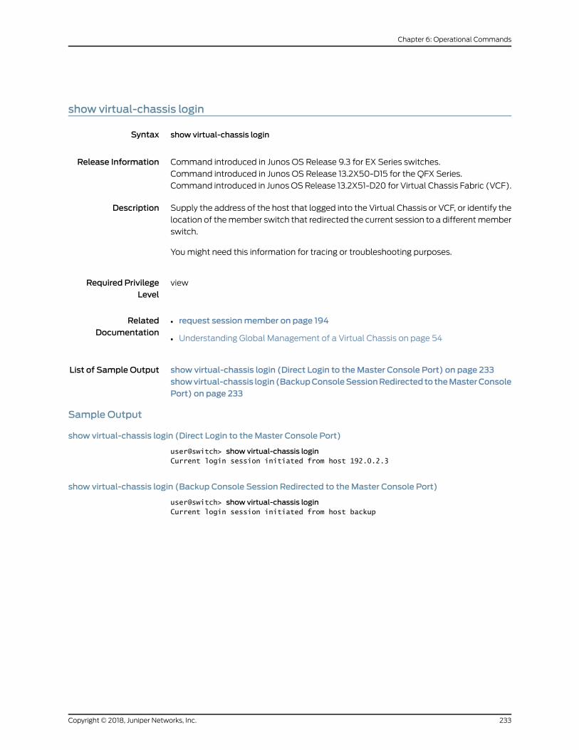
show virtual-chassis login
Syntax show virtual-chassis login
Release Information Command introduced in Junos OS Release 9.3 for EX Series switches.
Command introduced in Junos OS Release 13.2X50-D15 for the QFX Series.
Command introduced in Junos OSRelease 13.2X51-D20 for Virtual Chassis Fabric (VCF).
Description Supply the address of the host that logged into the Virtual Chassis or VCF, or identify the
location of themember switch that redirected the current session to a differentmember
switch.
Youmight need this information for tracing or troubleshooting purposes.
Required PrivilegeLevel
view
RelatedDocumentation
request sessionmember on page 194•
• Understanding Global Management of a Virtual Chassis on page 54
List of Sample Output show virtual-chassis login (Direct Login to theMaster Console Port) on page 233showvirtual-chassis login (BackupConsoleSessionRedirected to theMasterConsolePort) on page 233
Sample Output
show virtual-chassis login (Direct Login to theMaster Console Port)
user@switch> show virtual-chassis loginCurrent login session initiated from host 192.0.2.3
show virtual-chassis login (Backup Console Session Redirected to theMaster Console Port)
user@switch> show virtual-chassis loginCurrent login session initiated from host backup
233Copyright © 2018, Juniper Networks, Inc.
Chapter 6: Operational Commands

show virtual-chassis mode
Syntax show virtual-chassis mode<all-members><local><membermember-id>
Release Information Command introduced in Junos OS Release 11.1 for EX Series switches.
Command introduced in Junos OS Release 13.2X51-D20 for QFX Series devices.
Command introduced in Junos OSRelease 13.2X51-D20 for Virtual Chassis Fabric (VCF).
Currentmode and Futuremode after reboot fields introduced in Junos OS Release13.2X51-D20.
Description Display the Virtual Chassis or Virtual Chassis Fabric (VCF) mixedmode status.
Options none—Display the Virtual Chassis or VCFmixedmode status for the device onwhich thecommand is entered.
all-members—(Optional) Display the Virtual Chassis or VCFmixedmode status for allmember devices in the Virtual Chassis or VCF.
local—(Optional) Display the Virtual Chassis or VCFmixedmode status for the deviceon which the command is entered.
membermember-id—(Optional) Display the Virtual Chassis or VCFmixedmode statusfor the specified member device..
Required PrivilegeLevel
view
RelatedDocumentation
request virtual-chassis mode on page 205•
• Verifying the Virtual Chassis Fabric Mode Settings
• ConfiguringaMixedVirtualChassiswithEX4200,EX4500,andEX4550MemberSwitches
(CLI Procedure)
List of Sample Output show virtual-chassis mode (EX4200) on page 235show virtual-chassis mode (QFX5100) on page 235
Output Fields Table 14 on page 234 lists the output fields for the show virtual-chassismode command.
Table 14: show virtual-chassis mode Output Fields
Field DescriptionField Name
Specifies the mixedmode status of the member switch. Mixedmode is either Enabled or Disabled.MixedMode
Copyright © 2018, Juniper Networks, Inc.234
Virtual Chassis Feature Guide for Switches

Table 14: show virtual-chassis mode Output Fields (continued)
Field DescriptionField Name
Specifies the current mixed and fabric mode settings running on themember device or devices.
A device reboot is required to change the fabric ormixedmode. TheCurrentmode and Futuremode after rebootare different when themode has been changed but the device has not been rebooted.
Outputs include:
• Fabric withmixed devices—Fabric mode andmixedmode are enabled.
• Fabric with similar devices—Fabric mode is enabled andmixedmode is disabled.
• Virtual Chassis withmixed devices—Fabric mode is disabled andmixedmode is enabled.
• Virtual Chassis with similar devices—Fabric mode is disabled andmixedmode is disabled.
Currentmode
Specifies the mixed and fabric mode settings running on themember device or devices.
A device reboot is required to change the fabric ormixedmode. TheCurrentmode and Futuremode after rebootare different when themode has been changed but the device has not been rebooted.
Outputs include:
• Fabric withmixed devices—Fabric mode andmixedmode are enabled.
• Fabric with similar devices—Fabric mode is enabled andmixedmode is disabled.
• Virtual Chassis withmixed devices—Fabric mode is disabled andmixedmode is enabled.
• Virtual Chassis with similar devices—Fabric mode is disabled andmixedmode is disabled.
Futuremodeafter reboot
Sample Output
show virtual-chassis mode (EX4200)
user@switch>show virtual-chassis modefpc0:--------------------------------------------------------------------------Mixed Mode: Disabled
Sample Output
show virtual-chassis mode (QFX5100)
user@switch>show virtual-chassis modefpc0:--------------------------------------------------------------------------Current mode : Fabric with similar devicesFuture mode after reboot : Fabric with similar devices
fpc1:--------------------------------------------------------------------------Current mode : Fabric with similar devicesFuture mode after reboot : Fabric with similar devices
fpc2:--------------------------------------------------------------------------Current mode : Fabric with similar devicesFuture mode after reboot : Fabric with similar devices
235Copyright © 2018, Juniper Networks, Inc.
Chapter 6: Operational Commands

fpc3:--------------------------------------------------------------------------Current mode : Fabric with similar devicesFuture mode after reboot : Fabric with similar devices
fpc4:--------------------------------------------------------------------------Current mode : Fabric with similar devicesFuture mode after reboot : Fabric with similar devices
Copyright © 2018, Juniper Networks, Inc.236
Virtual Chassis Feature Guide for Switches

show virtual-chassis protocol adjacency
Syntax show virtual-chassis protocol adjacency<brief | detail | extensive><all-members><local><membermember-id><system-id>
Release Information Command introduced in Junos OS Release 10.4 for EX Series switches.
Command introduced in Junos OS Release 13.2X50-D15 for the QFX Series.
Command introduced in Junos OSRelease 13.2X51-D20 for Virtual Chassis Fabric (VCF).
Description Display the Virtual Chassis Control Protocol (VCCP) adjacency statistics in the Virtual
Chassis or VCF for all hardware devices.
Options none—Display VCCP adjacency statistics in brief form for all members of the Virtual
Chassis or VCF.
brief | detail | extensive—(Optional) Display the specified level of output. Using the briefoption is equivalent to entering the command with no options (the default). The
detail and extensive options provide identical displays.
all-members—(Optional)DisplayVCCPadjacency statistics inbrief formforallmembers
of the Virtual Chassis or VCF.
local—(Optional) Display VCCP adjacency statistics for the switch or external RoutingEngine on which this command is entered.
membermember-id—(Optional) Display VCCP adjacency statistics for the specifiedmember of the Virtual Chassis or VCF.
system-id—(Optional) Display VCCP adjacency statistics for the specified member ofthe Virtual Chassis or VCF.
Required PrivilegeLevel
clear
RelatedDocumentation
Understanding Virtual Chassis Port Link Aggregation on page 57•
• Understanding the Virtual Chassis Control Protocol in an EX8200 Virtual Chassis
List of Sample Output show virtual-chassis protocol adjacency on page 238show virtual-chassis protocol adjacency detail on page 239
Output Fields Table 15onpage238 lists theoutput fields for the showvirtual-chassisprotocoladjacency
command. Output fields are listed in the approximate order in which they appear.
237Copyright © 2018, Juniper Networks, Inc.
Chapter 6: Operational Commands

Table 15: show virtual-chassis protocol adjacency Output Fields
Level of OutputField DescriptionField Name
All levelsName of the Virtual Chassis port (VCP) interface.Interface
All levelsThe MAC address of the device on the receiving side of the VCP link.System
All levelsState of the link. Outputs include:
• Up—The link is up.
• Down—The link is down.
• New—The link is new.
• One-way—The link is transmitting traffic in one direction.
• Initializing—The link is initializing.
• Rejected—The link is rejected.
State
All levelsRemaining holdtime of the adjacency.Hold, Expires in
detailPriority to become the designated intermediary system.Priority
detailCount of adjacency status transition changes from up to down or down to up.Up/DownTransitions
detailTime of the last up/down transition.Last transition
Sample Output
show virtual-chassis protocol adjacency
user@switch> show virtual-chassis protocol adjacencymember0:--------------------------------------------------------------------------Interface System State Hold (secs)vcp-0/0.32768 0000.4a75.9b7c Up 57vcp-0/1.32768 0000.4a75.9b7c Up 59vcp-4/0/1.32768 0026.888d.6800 Up 57
member1:--------------------------------------------------------------------------Interface System State Hold (secs)vcp-0/0.32768 0000.4a75.9b7c Up 58vcp-0/1.32768 0000.73e9.9a57 Up 59vcp-3/0/4.32768 0021.59f7.d000 Up 58
member8:--------------------------------------------------------------------------Interface System State Hold (secs)vcp-1/0.32768 0000.73e9.9a57 Up 58vcp-1/1.32768 0021.59f7.d000 Up 58vcp-1/2.32768 0026.888d.6800 Up 59vcp-2/0.32768 0021.59f7.d000 Up 59
member9:--------------------------------------------------------------------------
Copyright © 2018, Juniper Networks, Inc.238
Virtual Chassis Feature Guide for Switches

Interface System State Hold (secs)vcp-1/0.32768 0000.4a75.9b7c Up 58vcp-1/1.32768 0026.888d.6800 Up 59
show virtual-chassis protocol adjacency detail
user@switch> show virtual-chassis protocol adjacency detailmember0:--------------------------------------------------------------------------
0000.4a75.9b7c interface-name: vcp-0/0.32768, State: Up, Expires in 57 secs Priority: 0, Up/Down transitions: 1, Last transition: 19:26:37 ago
0000.4a75.9b7c interface-name: vcp-0/1.32768, State: Up, Expires in 59 secs Priority: 0, Up/Down transitions: 1, Last transition: 19:26:37 ago
0026.888d.6800 interface-name: vcp-4/0/1.32768, State: Up, Expires in 59 secs Priority: 0, Up/Down transitions: 1, Last transition: 22:06:39 ago
member1:--------------------------------------------------------------------------
0000.4a75.9b7c interface-name: vcp-0/0.32768, State: Up, Expires in 59 secs Priority: 0, Up/Down transitions: 1, Last transition: 19:26:38 ago
0000.73e9.9a57 interface-name: vcp-0/1.32768, State: Up, Expires in 58 secs Priority: 0, Up/Down transitions: 1, Last transition: 22:17:36 ago
0021.59f7.d000 interface-name: vcp-3/0/4.32768, State: Up, Expires in 58 secs Priority: 0, Up/Down transitions: 1, Last transition: 22:06:39 ago
member8:--------------------------------------------------------------------------
0000.73e9.9a57 interface-name: vcp-1/0.32768, State: Up, Expires in 58 secs Priority: 0, Up/Down transitions: 1, Last transition: 19:26:38 ago
0021.59f7.d000 interface-name: vcp-1/1.32768, State: Up, Expires in 59 secs Priority: 0, Up/Down transitions: 1, Last transition: 19:26:38 ago
0026.888d.6800 interface-name: vcp-1/2.32768, State: Up, Expires in 59 secs Priority: 0, Up/Down transitions: 1, Last transition: 19:26:38 ago
0021.59f7.d000 interface-name: vcp-2/0.32768, State: Up, Expires in 57 secs Priority: 0, Up/Down transitions: 1, Last transition: 19:26:38 ago
member9:--------------------------------------------------------------------------
0000.4a75.9b7c interface-name: vcp-1/0.32768, State: Up, Expires in 59 secs
239Copyright © 2018, Juniper Networks, Inc.
Chapter 6: Operational Commands

Priority: 0, Up/Down transitions: 1, Last transition: 19:26:38 ago
0026.888d.6800 interface-name: vcp-1/1.32768, State: Up, Expires in 58 secs Priority: 0, Up/Down transitions: 1, Last transition: 22:17:36 ago
Copyright © 2018, Juniper Networks, Inc.240
Virtual Chassis Feature Guide for Switches

show virtual-chassis protocol database
Syntax show virtual-chassis protocol database<brief | detail | extensive><all-members><local><membermember-id>
Release Information Command introduced in Junos OS Release 10.4 for EX Series switches.
Command introduced in Junos OS Release 13.2X50-D15 for the QFX Series.
Command introduced in Junos OSRelease 13.2X51-D20 for Virtual Chassis Fabric (VCF).
Description Display the Virtual Chassis Control Protocol (VCCP) database statistics for all hardware
devices within the Virtual Chassis or VCF.
Options none—Display VCCP database statistics in brief form for all members of the Virtual
Chassis or VCF.
brief | detail | extensive—(Optional) Display the specified level of output. Using the briefoption is equivalent to entering the command with no options (the default). The
detailoptionprovidesmoreoutput than thebriefoption.Theextensiveoptionprovides
all output and is most useful for customer support personnel.
all-members—(Optional)DisplayVCCPdatabase statistics inbrief form for allmembers
of the Virtual Chassis or VCF.
local—(Optional) Display VCCP database statistics for the switch or external RoutingEngine on which this command is entered.
membermember-id—(Optional) Display VCCP database statistics for the specifiedmember of the Virtual Chassis or VCF.
Required PrivilegeLevel
clear
RelatedDocumentation
Understanding the Virtual Chassis Control Protocol in an EX8200 Virtual Chassis•
• Understanding Virtual Chassis Components on page 34
List of Sample Output show virtual-chassis protocol database on page 242show virtual-chassis protocol database detail on page 243
Output Fields Table 16 onpage 242 lists the output fields for the showvirtual-chassis protocol database
command. Output fields are listed in the approximate order in which they appear.
241Copyright © 2018, Juniper Networks, Inc.
Chapter 6: Operational Commands

Table 16: show virtual-chassis protocol database Output Fields
Level of OutputField DescriptionField Name
All levelsLink-state protocol (LSP) data unit identifier.LSP ID
All levelsSequence number of the LSP.Sequence
All levelsChecksum value of the LSP.Checksum
All levelsRemaining lifetime of the LSP, in seconds.Lifetime
detailMAC address of the neighbor on the advertising system.Neighbor
detailVirtual Chassis port (VCP) interface name.Interface
detailMetric of the prefix or neighbor.Metric
The extensive output was omitted from this list. The extensive output is useful for
customer support personnel only.
Sample Output
show virtual-chassis protocol database
user@switch> show virtual-chassis protocol databasemember0:--------------------------------------------------------------------------LSP ID Sequence Checksum Lifetime0000.4a75.9b7c.00-00 0x1dd80 0xc2e3 1160000.73e9.9a57.00-00 0xf361 0x27e8 1130021.59f7.d000.00-00 0x16882 0x3993 1180026.888d.6800.00-00 0x1691f 0x82b7 116 4 LSPs
member1:--------------------------------------------------------------------------LSP ID Sequence Checksum Lifetime0000.4a75.9b7c.00-00 0x1dd80 0xc2e3 1160000.73e9.9a57.00-00 0xf361 0x27e8 1140021.59f7.d000.00-00 0x16883 0x289 1160026.888d.6800.00-00 0x1691f 0x82b7 118 4 LSPs
member8:--------------------------------------------------------------------------LSP ID Sequence Checksum Lifetime0000.4a75.9b7c.00-00 0x1dd80 0xc2e3 1180000.73e9.9a57.00-00 0xf361 0x27e8 1140021.59f7.d000.00-00 0x16883 0x289 1160026.888d.6800.00-00 0x16920 0xa335 116 4 LSPs
member9:--------------------------------------------------------------------------LSP ID Sequence Checksum Lifetime
Copyright © 2018, Juniper Networks, Inc.242
Virtual Chassis Feature Guide for Switches
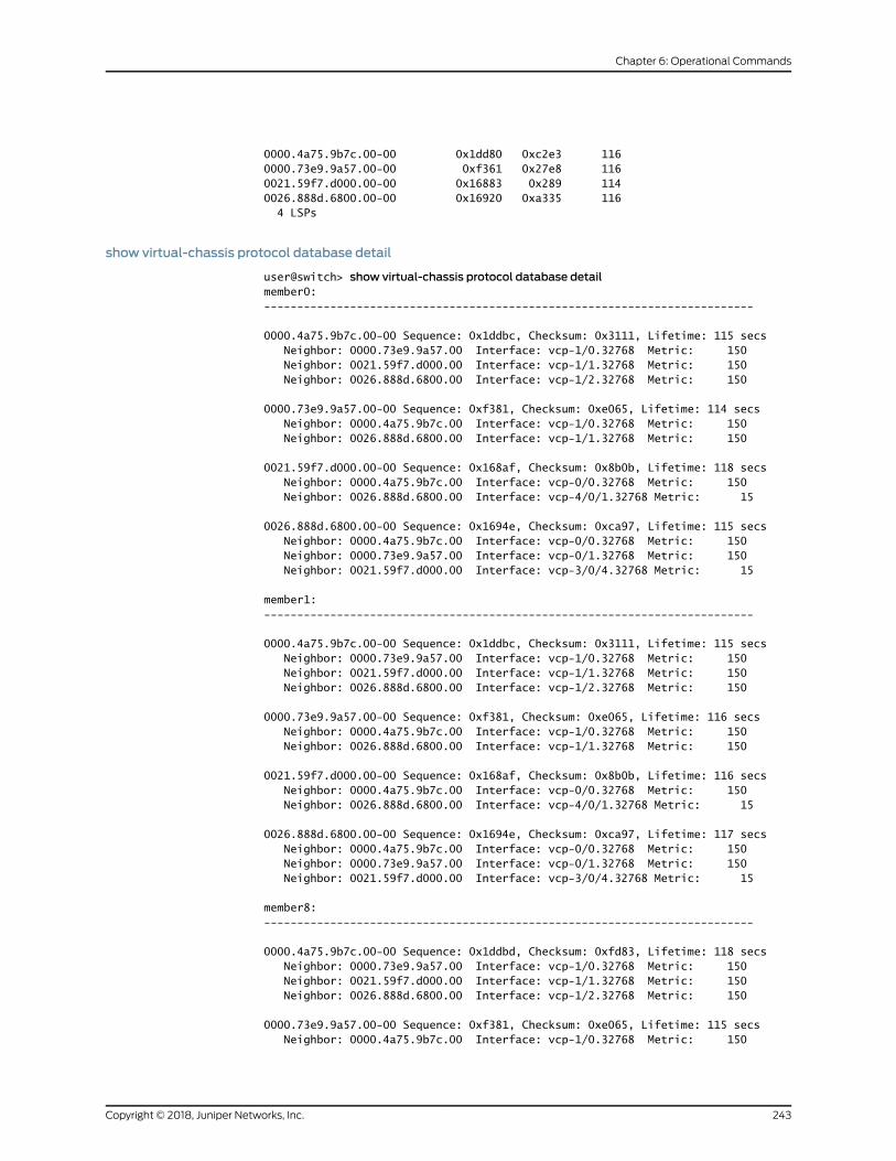
0000.4a75.9b7c.00-00 0x1dd80 0xc2e3 1160000.73e9.9a57.00-00 0xf361 0x27e8 1160021.59f7.d000.00-00 0x16883 0x289 1140026.888d.6800.00-00 0x16920 0xa335 116 4 LSPs
show virtual-chassis protocol database detail
user@switch> show virtual-chassis protocol database detailmember0:--------------------------------------------------------------------------
0000.4a75.9b7c.00-00 Sequence: 0x1ddbc, Checksum: 0x3111, Lifetime: 115 secs Neighbor: 0000.73e9.9a57.00 Interface: vcp-1/0.32768 Metric: 150 Neighbor: 0021.59f7.d000.00 Interface: vcp-1/1.32768 Metric: 150 Neighbor: 0026.888d.6800.00 Interface: vcp-1/2.32768 Metric: 150
0000.73e9.9a57.00-00 Sequence: 0xf381, Checksum: 0xe065, Lifetime: 114 secs Neighbor: 0000.4a75.9b7c.00 Interface: vcp-1/0.32768 Metric: 150 Neighbor: 0026.888d.6800.00 Interface: vcp-1/1.32768 Metric: 150
0021.59f7.d000.00-00 Sequence: 0x168af, Checksum: 0x8b0b, Lifetime: 118 secs Neighbor: 0000.4a75.9b7c.00 Interface: vcp-0/0.32768 Metric: 150 Neighbor: 0026.888d.6800.00 Interface: vcp-4/0/1.32768 Metric: 15
0026.888d.6800.00-00 Sequence: 0x1694e, Checksum: 0xca97, Lifetime: 115 secs Neighbor: 0000.4a75.9b7c.00 Interface: vcp-0/0.32768 Metric: 150 Neighbor: 0000.73e9.9a57.00 Interface: vcp-0/1.32768 Metric: 150 Neighbor: 0021.59f7.d000.00 Interface: vcp-3/0/4.32768 Metric: 15
member1:--------------------------------------------------------------------------
0000.4a75.9b7c.00-00 Sequence: 0x1ddbc, Checksum: 0x3111, Lifetime: 115 secs Neighbor: 0000.73e9.9a57.00 Interface: vcp-1/0.32768 Metric: 150 Neighbor: 0021.59f7.d000.00 Interface: vcp-1/1.32768 Metric: 150 Neighbor: 0026.888d.6800.00 Interface: vcp-1/2.32768 Metric: 150
0000.73e9.9a57.00-00 Sequence: 0xf381, Checksum: 0xe065, Lifetime: 116 secs Neighbor: 0000.4a75.9b7c.00 Interface: vcp-1/0.32768 Metric: 150 Neighbor: 0026.888d.6800.00 Interface: vcp-1/1.32768 Metric: 150
0021.59f7.d000.00-00 Sequence: 0x168af, Checksum: 0x8b0b, Lifetime: 116 secs Neighbor: 0000.4a75.9b7c.00 Interface: vcp-0/0.32768 Metric: 150 Neighbor: 0026.888d.6800.00 Interface: vcp-4/0/1.32768 Metric: 15
0026.888d.6800.00-00 Sequence: 0x1694e, Checksum: 0xca97, Lifetime: 117 secs Neighbor: 0000.4a75.9b7c.00 Interface: vcp-0/0.32768 Metric: 150 Neighbor: 0000.73e9.9a57.00 Interface: vcp-0/1.32768 Metric: 150 Neighbor: 0021.59f7.d000.00 Interface: vcp-3/0/4.32768 Metric: 15
member8:--------------------------------------------------------------------------
0000.4a75.9b7c.00-00 Sequence: 0x1ddbd, Checksum: 0xfd83, Lifetime: 118 secs Neighbor: 0000.73e9.9a57.00 Interface: vcp-1/0.32768 Metric: 150 Neighbor: 0021.59f7.d000.00 Interface: vcp-1/1.32768 Metric: 150 Neighbor: 0026.888d.6800.00 Interface: vcp-1/2.32768 Metric: 150
0000.73e9.9a57.00-00 Sequence: 0xf381, Checksum: 0xe065, Lifetime: 115 secs Neighbor: 0000.4a75.9b7c.00 Interface: vcp-1/0.32768 Metric: 150
243Copyright © 2018, Juniper Networks, Inc.
Chapter 6: Operational Commands

Neighbor: 0026.888d.6800.00 Interface: vcp-1/1.32768 Metric: 150
0021.59f7.d000.00-00 Sequence: 0x168af, Checksum: 0x8b0b, Lifetime: 116 secs Neighbor: 0000.4a75.9b7c.00 Interface: vcp-0/0.32768 Metric: 150 Neighbor: 0026.888d.6800.00 Interface: vcp-4/0/1.32768 Metric: 15
0026.888d.6800.00-00 Sequence: 0x1694e, Checksum: 0xca97, Lifetime: 115 secs Neighbor: 0000.4a75.9b7c.00 Interface: vcp-0/0.32768 Metric: 150 Neighbor: 0000.73e9.9a57.00 Interface: vcp-0/1.32768 Metric: 150 Neighbor: 0021.59f7.d000.00 Interface: vcp-3/0/4.32768 Metric: 15
member9:--------------------------------------------------------------------------
0000.4a75.9b7c.00-00 Sequence: 0x1ddbd, Checksum: 0xfd83, Lifetime: 116 secs Neighbor: 0000.73e9.9a57.00 Interface: vcp-1/0.32768 Metric: 150 Neighbor: 0021.59f7.d000.00 Interface: vcp-1/1.32768 Metric: 150 Neighbor: 0026.888d.6800.00 Interface: vcp-1/2.32768 Metric: 150
0000.73e9.9a57.00-00 Sequence: 0xf381, Checksum: 0xe065, Lifetime: 117 secs Neighbor: 0000.4a75.9b7c.00 Interface: vcp-1/0.32768 Metric: 150 Neighbor: 0026.888d.6800.00 Interface: vcp-1/1.32768 Metric: 150
0021.59f7.d000.00-00 Sequence: 0x168af, Checksum: 0x8b0b, Lifetime: 113 secs Neighbor: 0000.4a75.9b7c.00 Interface: vcp-0/0.32768 Metric: 150 Neighbor: 0026.888d.6800.00 Interface: vcp-4/0/1.32768 Metric: 15
0026.888d.6800.00-00 Sequence: 0x1694f, Checksum: 0xa61a, Lifetime: 116 secs Neighbor: 0000.4a75.9b7c.00 Interface: vcp-0/0.32768 Metric: 150 Neighbor: 0000.73e9.9a57.00 Interface: vcp-0/1.32768 Metric: 150 Neighbor: 0021.59f7.d000.00 Interface: vcp-3/0/4.32768 Metric: 15
Copyright © 2018, Juniper Networks, Inc.244
Virtual Chassis Feature Guide for Switches

show virtual-chassis protocol interface
Syntax show virtual-chassis protocol interface<brief | detail><all-members><interface-name><local><membermember-id>
Release Information Command introduced in Junos OS Release 10.4 for EX Series switches.
Command introduced in Junos OS Release 13.2X50-D15 for the QFX Series.
Command introduced in Junos OSRelease 13.2X51-D20 for Virtual Chassis Fabric (VCF).
Description Display information about Virtual Chassis Control Protocol (VCCP) statistics for
VCCP-enabled interfaces within the Virtual Chassis or VCF.
Options none—Display the VCCP interface statistics in brief form for all members of the Virtual
Chassis or VCF.
brief | detail—(Optional) Display the specified level of output. Using the brief option isequivalent to entering the commandwith no options (the default). The detailoption
provides more output than the brief option.
all-members—(Optional)DisplayVCCP interface statistics for allmembersof theVirtualChassis or VCF.
interface-name—(Optional) Display VCCP interface statistics for the specified interface.
local—(Optional) Display VCCP interface statistics for the switch or external RoutingEngine on which this command is entered.
membermember-id—(Optional) Display VCCP interface statistics for the specifiedmember of the Virtual Chassis or VCF.
Required PrivilegeLevel
clear
RelatedDocumentation
EX Series Virtual Chassis Overview on page 19•
• Understanding QFX Series Virtual Chassis on page 29
• Understanding Virtual Chassis Ports in an EX8200 Virtual Chassis
• Understanding the Virtual Chassis Control Protocol in an EX8200 Virtual Chassis
List of Sample Output show virtual-chassis protocol interface on page 246
Output Fields Table 17 on page 246 lists the output fields for the showvirtual-chassis protocol interface
command. Output fields are listed in the approximate order in which they appear.
245Copyright © 2018, Juniper Networks, Inc.
Chapter 6: Operational Commands
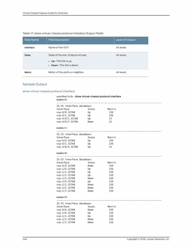
Table 17: show virtual-chassis protocol interface Output Fields
Level of OutputField DescriptionField Name
All levelsName of the VCP.Interface
All levelsState of the link. Outputs include:
• Up—The link is up.
• Down—The link is down.
State
All levelsMetric of the prefix or neighbor.Metric
Sample Output
show virtual-chassis protocol interface
user@switch> show virtual-chassis protocol interfacemember0:--------------------------------------------------------------------------IS-IS interface database:Interface State Metricvcp-0/0.32768 Up 150vcp-0/1.32768 Up 150vcp-4/0/1.32768 Up 15vcp-4/0/7.32768 Down 15
member1:--------------------------------------------------------------------------IS-IS interface database:Interface State Metricvcp-0/0.32768 Up 150vcp-0/1.32768 Up 150vcp-3/0/4.32768 Up 15
member8:--------------------------------------------------------------------------IS-IS interface database:Interface State Metricvcp-0/0.32768 Down 150vcp-1/0.32768 Up 150vcp-1/1.32768 Up 150vcp-1/2.32768 Up 150vcp-1/3.32768 Down 150vcp-2/0.32768 Up 150vcp-2/1.32768 Down 150vcp-2/2.32768 Down 150vcp-2/3.32768 Down 150
member9:--------------------------------------------------------------------------IS-IS interface database:Interface State Metricvcp-0/0.32768 Down 150vcp-1/0.32768 Up 150vcp-1/1.32768 Up 150vcp-1/2.32768 Down 150vcp-1/3.32768 Down 150
Copyright © 2018, Juniper Networks, Inc.246
Virtual Chassis Feature Guide for Switches
247Copyright © 2018, Juniper Networks, Inc.
Chapter 6: Operational Commands

show virtual-chassis protocol route
Syntax show virtual-chassis protocol route<all-members><destination-id><local><membermember-id>
Release Information Command introduced in Junos OS Release 10.4 for EX Series switches.
Command introduced in Junos OS Release 13.2X50-D15 for the QFX Series.
Command introduced in Junos OSRelease 13.2X51-D20 for Virtual Chassis Fabric (VCF).
Description Display the unicast andmulticast Virtual Chassis Control Protocol (VCCP) routing tables
within the Virtual Chassis or VCF.
Options none—Display the unicast andmulticast routing tables for all members of the VirtualChassis.
all-members—(Optional)Display theunicastandmulticast routing tables forallmembersof the Virtual Chassis or VCF.
destination-id—(Optional)Display theunicastandmulticast routing tables to thespecifieddestination member ID for eachmember of the Virtual Chassis or VCF.
local—(Optional) Display the unicast andmulticast routing tables on the device wherethis command is entered.
membermember-id—(Optional) Display the unicast andmulticast routing tables for thespecified member of the Virtual Chassis or VCF.
Required PrivilegeLevel
clear
RelatedDocumentation
EX Series Virtual Chassis Overview on page 19•
• Understanding QFX Series Virtual Chassis on page 29
• Understanding the Virtual Chassis Control Protocol in an EX8200 Virtual Chassis
List of Sample Output show virtual-chassis protocol route on page 249
Output Fields Table 18 on page 248 lists the output fields for the show virtual-chassis protocol route
command. Output fields are listed in the approximate order in which they appear.
Table 18: show virtual-chassis protocol route Output Fields
Field DescriptionField Name
MAC address of the member storing the VCCP routing table.Dev
Copyright © 2018, Juniper Networks, Inc.248
Virtual Chassis Feature Guide for Switches

Table 18: show virtual-chassis protocol route Output Fields (continued)
Field DescriptionField Name
Version of the shortest-path-first algorithm that generated the routing table.Version
MAC address of the device.System ID
Version of the shortest-path-first (SPF) algorithm that generated the route.Version
Themetric number to get to that device.Metric
Name of the Virtual Chassis port (VCP) interface connecting the devices.Interface
MAC address of the next-hop device, if applicable.Via
Sample Output
show virtual-chassis protocol route
user@switch> show virtual-chassis protocol routemember0:--------------------------------------------------------------------------
Dev 0021.59f7.d000 ucast routing table Current version: 21----------------System ID Version Metric Interface Via0000.4a75.9b7c 21 150 vcp-0/1.32768 0000.4a75.9b7c0000.73e9.9a57 21 165 vcp-4/0/1.32768 0026.888d.68000021.59f7.d000 21 00026.888d.6800 21 15 vcp-4/0/1.32768 0026.888d.6800
Dev 0021.59f7.d000 mcast routing table Current version: 21----------------System ID Version Metric Interface Via0000.4a75.9b7c 210000.73e9.9a57 210021.59f7.d000 21 vcp-4/0/1.32768 vcp-0/1.327680026.888d.6800 21
member1:--------------------------------------------------------------------------
Dev 0026.888d.6800 ucast routing table Current version: 25----------------System ID Version Metric Interface Via0000.4a75.9b7c 25 150 vcp-0/0.32768 0000.4a75.9b7c0000.73e9.9a57 25 150 vcp-0/1.32768 0000.73e9.9a570021.59f7.d000 25 15 vcp-3/0/4.32768 0021.59f7.d0000026.888d.6800 25 0
Dev 0026.888d.6800 mcast routing table Current version: 25----------------System ID Version Metric Interface Via0000.4a75.9b7c 250000.73e9.9a57 25 vcp-3/0/4.32768
249Copyright © 2018, Juniper Networks, Inc.
Chapter 6: Operational Commands

0021.59f7.d000 25 vcp-0/1.327680026.888d.6800 25 vcp-3/0/4.32768 vcp-0/0.32768 vcp-0/1.32768
member8:--------------------------------------------------------------------------
Dev 0000.4a75.9b7c ucast routing table Current version: 39----------------System ID Version Metric Interface Via0000.4a75.9b7c 39 00000.73e9.9a57 39 150 vcp-1/0.32768 0000.73e9.9a570021.59f7.d000 39 150 vcp-2/0.32768 0021.59f7.d0000026.888d.6800 39 150 vcp-1/2.32768 0026.888d.6800
Dev 0000.4a75.9b7c mcast routing table Current version: 39----------------System ID Version Metric Interface Via0000.4a75.9b7c 39 vcp-1/0.32768 vcp-2/0.32768 vcp-1/2.327680000.73e9.9a57 390021.59f7.d000 390026.888d.6800 39
member9:--------------------------------------------------------------------------
Dev 0000.73e9.9a57 ucast routing table Current version: 31----------------System ID Version Metric Interface Via0000.4a75.9b7c 31 150 vcp-1/0.32768 0000.4a75.9b7c0000.73e9.9a57 31 00021.59f7.d000 31 165 vcp-1/1.32768 0026.888d.68000026.888d.6800 31 150 vcp-1/1.32768 0026.888d.6800
Dev 0000.73e9.9a57 mcast routing table Current version: 31----------------System ID Version Metric Interface Via0000.4a75.9b7c 310000.73e9.9a57 31 vcp-1/0.32768 vcp-1/1.327680021.59f7.d000 310026.888d.6800 31
Copyright © 2018, Juniper Networks, Inc.250
Virtual Chassis Feature Guide for Switches

show virtual-chassis protocol statistics
Syntax show virtual-chassis protocol statistics<all-members><interface-name><local><membermember-id>
Release Information Command introduced in Junos OS Release 10.4 for EX Series switches.
Command introduced in Junos OS Release 13.2X50-D15 for the QFX Series.
Command introduced in Junos OSRelease 13.2X51-D20 for Virtual Chassis Fabric (VCF).
Description Display the Virtual Chassis Control Protocol (VCCP) statistics for all hardware devices
within the Virtual Chassis or VCF.
Options none—Display VCCP statistics for all members of the Virtual Chassis or VCF.
all-members—(Optional) Display VCCP statistics for all members of the Virtual Chassisor VCF.
interface-name—(Optional) Display VCCP statistics for the specified interface.
local—(Optional) Display VCCP statistics for the switch or external Routing Engine onwhich this command is entered.
membermember-id—(Optional) Display VCCP statistics for the specified member ofthe Virtual Chassis or VCF.
Required PrivilegeLevel
clear
RelatedDocumentation
EX Series Virtual Chassis Overview on page 19•
• Understanding QFX Series Virtual Chassis on page 29
• Understanding the Virtual Chassis Control Protocol in an EX8200 Virtual Chassis
List of Sample Output show virtual-chassis protocol statistics on page 252
Output Fields Table 19 on page 251 lists the output fields for the show virtual-chassis protocol interface
command. Output fields are listed in the approximate order in which they appear.
Table 19: show virtual-chassis protocol statistics Output Fields
Field DescriptionField Name
Protocol data unit type.PDU type
Number of PDUs received since VCCP started or since the statistics were set to zero.Received
251Copyright © 2018, Juniper Networks, Inc.
Chapter 6: Operational Commands

Table 19: show virtual-chassis protocol statistics Output Fields (continued)
Field DescriptionField Name
Number of PDUs receivedminus the number of PDUs dropped.Processed
Number of PDUs dropped.Drops
Number of PDUs transmitted since VCCP started or since the statistics were set to zero.Sent
Number of PDUs retransmitted since VCCP started or since the statistics were set to zero.Rexmit
Number of PDUs received since VCCP started or since the statistics were set to zero.Total PacketsReceived
Number of PDUs sent since VCCP started or since the statistics were set to zero.TotalPacketsSent
Number of link-state PDUs waiting in the queue for processing. This value is almost always 0.LSP queue length
Number of shortest-path-first (SPF) calculations that have been performed.SPF runs
Number of link-state PDU fragments that the local system has computed.Fragments Rebuilt
Number of link-state PDUs that have been regenerated. A link-state PDU is regenerated when it is nearingthe end of its lifetime and it has not changed.
LSPRegenerations
Number of purges that the system initiated. A purge is initiated if the software determines that a link-statePDUmust be removed from the network.
Purges initiated
Sample Output
show virtual-chassis protocol statistics
user@switch> show virtual-chassis protocol statisticsmember0:--------------------------------------------------------------------------
IS-IS statistics for 0021.59f7.d000:PDU type Received Processed Drops Sent RexmitLSP 8166 8166 0 4551 0HELLO 1659 1659 0 1693 0CSNP 2 2 0 3 0PSNP 1909 1909 0 2293 0Unknown 0 0 0 0 0Totals 11736 11736 0 8540 0
Total packets received: 11736 Sent: 8540
LSP queue length: 0 Drops: 0SPF runs: 9Fragments rebuilt: 1640LSP regenerations: 1Purges initiated: 0
member1:
Copyright © 2018, Juniper Networks, Inc.252
Virtual Chassis Feature Guide for Switches

--------------------------------------------------------------------------
IS-IS statistics for 0026.888d.6800:PDU type Received Processed Drops Sent RexmitLSP 10909 10909 0 12088 0HELLO 1877 1877 0 2251 0CSNP 3 3 0 3 0PSNP 3846 3846 0 3732 0Unknown 0 0 0 0 0Totals 16635 16635 0 18074 0
Total packets received: 16635 Sent: 18074
LSP queue length: 0 Drops: 0SPF runs: 13Fragments rebuilt: 1871LSP regenerations: 2Purges initiated: 0
member8:--------------------------------------------------------------------------
IS-IS statistics for 0000.4a75.9b7c:PDU type Received Processed Drops Sent RexmitLSP 7935 7935 0 14865 0HELLO 2695 2695 0 7124 0CSNP 4 4 0 4 0PSNP 4398 4398 0 3666 0Unknown 0 0 0 0 0Totals 15032 15032 0 25659 0
Total packets received: 15032 Sent: 25659
LSP queue length: 0 Drops: 0SPF runs: 26Fragments rebuilt: 2666LSP regenerations: 4Purges initiated: 0
member9:--------------------------------------------------------------------------
IS-IS statistics for 0000.73e9.9a57:PDU type Received Processed Drops Sent RexmitLSP 10800 10800 0 6327 0HELLO 1492 1492 0 2356 0CSNP 2 2 0 2 0PSNP 2683 2683 0 3149 0Unknown 0 0 0 0 0Totals 14977 14977 0 11834 0
Total packets received: 14977 Sent: 11834
LSP queue length: 0 Drops: 0SPF runs: 19Fragments rebuilt: 1510LSP regenerations: 6Purges initiated: 0
253Copyright © 2018, Juniper Networks, Inc.
Chapter 6: Operational Commands
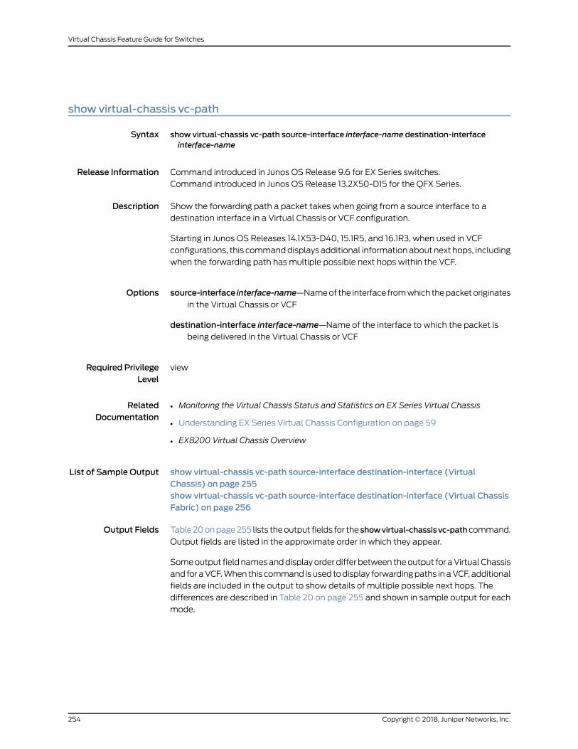
show virtual-chassis vc-path
Syntax show virtual-chassis vc-path source-interface interface-name destination-interfaceinterface-name
Release Information Command introduced in Junos OS Release 9.6 for EX Series switches.
Command introduced in Junos OS Release 13.2X50-D15 for the QFX Series.
Description Show the forwarding path a packet takes when going from a source interface to a
destination interface in a Virtual Chassis or VCF configuration.
Starting in Junos OS Releases 14.1X53-D40, 15.1R5, and 16.1R3, when used in VCF
configurations, this commanddisplays additional information about next hops, including
when the forwarding path has multiple possible next hops within the VCF.
Options source-interface interface-name—Nameof the interface fromwhich thepacketoriginates
in the Virtual Chassis or VCF
destination-interface interface-name—Name of the interface to which the packet isbeing delivered in the Virtual Chassis or VCF
Required PrivilegeLevel
view
RelatedDocumentation
Monitoring the Virtual Chassis Status and Statistics on EX Series Virtual Chassis•
• Understanding EX Series Virtual Chassis Configuration on page 59
• EX8200 Virtual Chassis Overview
List of Sample Output show virtual-chassis vc-path source-interface destination-interface (VirtualChassis) on page 255show virtual-chassis vc-path source-interface destination-interface (Virtual ChassisFabric) on page 256
Output Fields Table20onpage255 lists theoutput fields for the showvirtual-chassisvc-pathcommand.
Output fields are listed in the approximate order in which they appear.
Someoutput fieldnamesanddisplayorderdiffer between theoutput for aVirtualChassis
and for aVCF.When this command isused todisplay forwardingpaths inaVCF, additional
fields are included in the output to show details of multiple possible next hops. The
differences are described in Table 20 on page 255 and shown in sample output for each
mode.
Copyright © 2018, Juniper Networks, Inc.254
Virtual Chassis Feature Guide for Switches

Table 20: show virtual-chassis vc-path Output Fields
Field DescriptionField Name
The hop number along the path between the source anddestination interfaces.The first hop entry (Hop0) is the packet’s source, intermediate hop informationrepresents transitions through themembers within the Virtual Chassis or VCF,and the last hop entry represents arrival at the packet’s destination.
For VCFoutput, eachHop entry also shows information aboutmultiple possiblenext hops towards the destination. SeeNext-hopPFE, Interface, and Bandwidthoutput field descriptions for details.
Hop
The Virtual Chassis or VCFmember ID of the switch that contains the PacketForwarding Engine for each hop through which the packet passes.
Member (VirtualChassis)
Member-ID (VCF)
The number of the Packet Forwarding Engine in each Virtual Chassis or VCFmember through which a packet passes.
For Virtual Chassis output, thePacket Forwarding Engine in each row is the nexthop of the preceding Packet Forwarding Engine, including intermediatetransitions throughmembers within the Virtual Chassis.
VCF output is expanded onmultiple rows to showmore information aboutmultiplepossiblenexthops—eachhopentry is followedbyoneormoreNext-hopPFE output fields with interface name and bandwidth information for eachpossible next hop.
PFE-Device(VirtualChassis)
PFE(VCF)
One or more possible next-hop Packet Forwarding Engine numbers for VCFmemberMember-ID. Each Next-hop entry includes the next-hops’s interfacename and bandwidth.
Next-hop PFE (VCFonly)
The name of the interface through which the Packet Forwarding Engines areconnected. The interface for the first hop (Hop0) is always the source interface.
VCF output provides more information about multiple possible next hops foreachhopentry, listing the Interfaceand the interfaceBandwidth for eachpossibleNext-hop PFE.
Interface
The bandwidth (in Gbps) of the next-hop interface for the associatedNext-hopPFE entry.
Bandwidth (VCFonly)
Sample Output
show virtual-chassis vc-path source-interface destination-interface (Virtual Chassis)
user@switch> show virtual-chassis vc-path source-interface ge-0/0/0 destination-interface ge-1/0/1
vc-path from ge-0/0/0 to ge-1/0/1Hop Member PFE-Device Interface0 0 1 ge-0/0/0 1 0 0 internal-1/24 2 1 3 vcp-0 3 1 4 ge-1/0/1
255Copyright © 2018, Juniper Networks, Inc.
Chapter 6: Operational Commands
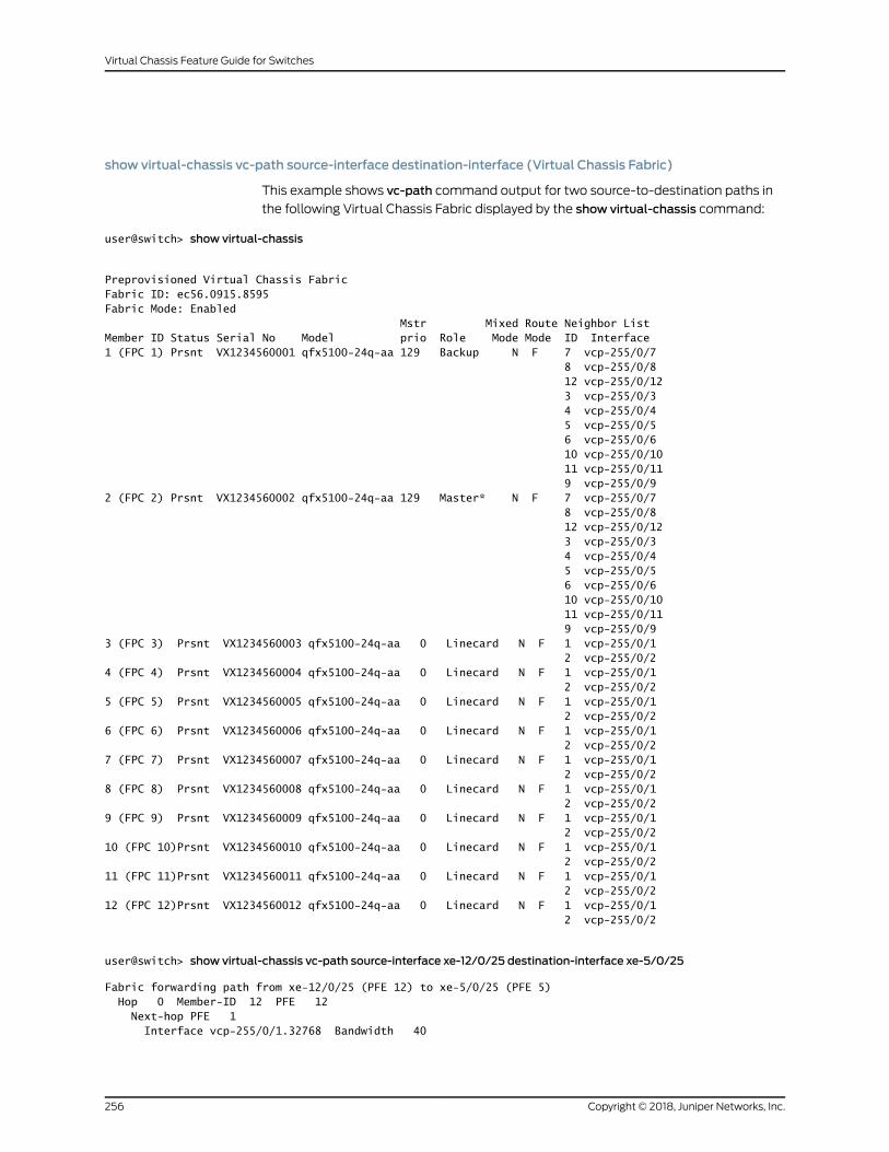
show virtual-chassis vc-path source-interface destination-interface (Virtual Chassis Fabric)
This example shows vc-path command output for two source-to-destination paths in
the following Virtual Chassis Fabric displayed by the show virtual-chassis command:
user@switch> show virtual-chassis
Preprovisioned Virtual Chassis FabricFabric ID: ec56.0915.8595Fabric Mode: Enabled Mstr Mixed Route Neighbor ListMember ID Status Serial No Model prio Role Mode Mode ID Interface1 (FPC 1) Prsnt VX1234560001 qfx5100-24q-aa 129 Backup N F 7 vcp-255/0/7 8 vcp-255/0/8 12 vcp-255/0/12 3 vcp-255/0/3 4 vcp-255/0/4 5 vcp-255/0/5 6 vcp-255/0/6 10 vcp-255/0/10 11 vcp-255/0/11 9 vcp-255/0/92 (FPC 2) Prsnt VX1234560002 qfx5100-24q-aa 129 Master* N F 7 vcp-255/0/7 8 vcp-255/0/8 12 vcp-255/0/12 3 vcp-255/0/3 4 vcp-255/0/4 5 vcp-255/0/5 6 vcp-255/0/6 10 vcp-255/0/10 11 vcp-255/0/11 9 vcp-255/0/93 (FPC 3) Prsnt VX1234560003 qfx5100-24q-aa 0 Linecard N F 1 vcp-255/0/1 2 vcp-255/0/24 (FPC 4) Prsnt VX1234560004 qfx5100-24q-aa 0 Linecard N F 1 vcp-255/0/1 2 vcp-255/0/25 (FPC 5) Prsnt VX1234560005 qfx5100-24q-aa 0 Linecard N F 1 vcp-255/0/1 2 vcp-255/0/26 (FPC 6) Prsnt VX1234560006 qfx5100-24q-aa 0 Linecard N F 1 vcp-255/0/1 2 vcp-255/0/27 (FPC 7) Prsnt VX1234560007 qfx5100-24q-aa 0 Linecard N F 1 vcp-255/0/1 2 vcp-255/0/28 (FPC 8) Prsnt VX1234560008 qfx5100-24q-aa 0 Linecard N F 1 vcp-255/0/1 2 vcp-255/0/29 (FPC 9) Prsnt VX1234560009 qfx5100-24q-aa 0 Linecard N F 1 vcp-255/0/1 2 vcp-255/0/210 (FPC 10)Prsnt VX1234560010 qfx5100-24q-aa 0 Linecard N F 1 vcp-255/0/1 2 vcp-255/0/211 (FPC 11)Prsnt VX1234560011 qfx5100-24q-aa 0 Linecard N F 1 vcp-255/0/1 2 vcp-255/0/212 (FPC 12)Prsnt VX1234560012 qfx5100-24q-aa 0 Linecard N F 1 vcp-255/0/1 2 vcp-255/0/2
user@switch> show virtual-chassis vc-path source-interface xe-12/0/25 destination-interface xe-5/0/25
Fabric forwarding path from xe-12/0/25 (PFE 12) to xe-5/0/25 (PFE 5) Hop 0 Member-ID 12 PFE 12 Next-hop PFE 1 Interface vcp-255/0/1.32768 Bandwidth 40
Copyright © 2018, Juniper Networks, Inc.256
Virtual Chassis Feature Guide for Switches

Next-hop PFE 2 Interface vcp-255/0/2.32768 Bandwidth 40 Hop 1 Member-ID 1 PFE 1 Next-hop PFE 5 Interface vcp-255/0/5.32768 Bandwidth 40 Hop 1 Member-ID 2 PFE 2 Next-hop PFE 5 Interface vcp-255/0/5.32768 Bandwidth 40 Hop 2 Member-ID 5 PFE 5
user@switch> show virtual-chassis vc-path source-interface xe-12/0/25 destination-interface xe-1/0/25
Fabric forwarding path from xe-12/0/25 (PFE 12) to xe-1/0/25 (PFE 1) Hop 0 Member-ID 12 PFE 12 Next-hop PFE 1 Interface vcp-255/0/1.32768 Bandwidth 40 Hop 1 Member-ID 1 PFE 1
257Copyright © 2018, Juniper Networks, Inc.
Chapter 6: Operational Commands

show virtual-chassis vc-port
Syntax show virtual-chassis vc-port<all-members><local><membermember-id>
Release Information Command introduced in Junos OS Release 9.0 for EX Series switches.
Command introduced in Junos OS Release 13.2X50-D15 for the QFX Series.
Command introduced in Junos OSRelease 13.2X51-D20 for Virtual Chassis Fabric (VCF).
Description Display the status of the Virtual Chassis ports (VCPs), including both dedicated VCPs
and uplink ports configured as VCPs, if present.
Options none—Display the operational status of all VCPs of the member switch where thecommand is issued.
all-members—(Optional) Display the operational status of all VCPs on all members ofthe Virtual Chassis or VCF.
local—(Optional) Display the operational status of the switch or external Routing Engineon which this command is entered.
membermember-id—(Optional) Display the operational status of all VCPs for thespecified member of the Virtual Chassis or VCF.
Required PrivilegeLevel
view
RelatedDocumentation
show virtual-chassis vc-port statistics on page 276•
• Monitoring the Virtual Chassis Status and Statistics on EX Series Virtual Chassis
List of Sample Output show virtual-chassis vc-port (EX4200 Virtual Chassis) on page 260show virtual-chassis vc-port (EX8200 Virtual Chassis) on page 260show virtual-chassis vc-port all-members on page 261
Output Fields Table 21 onpage258 lists theoutput fields for the showvirtual-chassisvc-portcommand.
Output fields are listed in the approximate order in which they appear.
Table 21: show virtual-chassis vc-port Output Fields
Field DescriptionField Name
The FPC number is the same as themember ID.fpcnumber
Copyright © 2018, Juniper Networks, Inc.258
Virtual Chassis Feature Guide for Switches

Table 21: show virtual-chassis vc-port Output Fields (continued)
Field DescriptionField Name
VCP name.
• The dedicated VCPs in an EX4200 or EX4500 Virtual Chassis are vcp-0 and vcp-1. The dedicatedVCPs in an EX4550 Virtual Chassis are VCP-1/0, VCP-1/1, VCP-2/0, and VCP-2/1.
• Optical ports set asVCPsare named 1/0and 1/1, representing thePIC number and theport number.
• The native VCP (port 0) on an XRE200 External Routing Engine in an EX8200 Virtual Chassis isnamed vcp-0.
• The VCPs on each Virtual Chassis Control Interface (VCCI) module in an XRE200 External RoutingEngine are named using the vcp-slot-number/port-number convention; for instance, vcp-1/0.
• The VCPs on EX8200member switches are named using thevcp-slot-number/pic-number/interface-number convention; for instance, vcp-3/0/2.
• A 255 as the first number in your port number indicates that your VCP is part of a Link Aggregationgroup (LAG)bundle. For instance, adisplayof vcp-255/1/0 indicates that thededicatedVCPnamedvcp-1/0 is part of a LAG bundle. A display of vcp-255/1/0 indicates that an uplink port that waspreviously named xe-0/1/0 is now part of a VCP LAG bundle.
Interface or PIC/Port
Type of VCP:
• Dedicated—The rearpanelVCPonanEX4200,EX4500.orEX4550switch.oranyVCP linkconnectedto an XRE200 External Routing Engine in an EX8200 Virtual Chassis.
• Configured—Optical port configured as a VCP.
• Auto-Configured—Optical port autoconfigured as a VCP.
See “SettinganUplinkPort onanEXSeriesorQFXSeriesSwitchasaVirtualChassisPort” onpage 108or “Configuring a QFX Series Virtual Chassis (CLI Procedure)” on page 84 for information aboutconfiguring VCPs.
Type
A positive-number ID assigned to a link aggregation group (LAG) formed by the Virtual Chassis. Thetrunk ID value is –1 if no trunk is formed. A LAG between uplink VCPs requires that the link speed bethe same on connected interfaces and that at least two VCPs on onemember be connected to atleast two VCPs on the other member in an EX4200 or EX4500 Virtual Chassis.
Dedicated VCP LAGs are assigned trunk IDs 1 and 2. Trunk IDs for LAGs formed with uplink VCPstherefore have values of 3 or greater.
The trunk ID value changes if the link-adjacency state between LAGmembers changes; trunkmembership is then allocated or deallocated.
Trunk ID
Interface status:
• absent—Interface is not a VCP link.
• down—VCP link is down.
• up—VCP link is up.
Status
Speed of the interface in megabits per second.Speed (mbps)
TheVirtual Chassismember ID and interface of a VCPon amember that is connected to the interfaceor PIC/Port field in the same row as this interface.
Neighbor ID/Interface
259Copyright © 2018, Juniper Networks, Inc.
Chapter 6: Operational Commands

Sample Output
show virtual-chassis vc-port (EX4200 Virtual Chassis)
user@switch> show virtual-chassis vc-port
fpc0:-------------------------------------------------------------------------–Interface Type Trunk Status Speed Neighboror ID (mbps) ID InterfacePIC / Portvcp-0 Dedicated 1 Up 32000 1 vcp-1vcp-1 Dedicated 2 Up 32000 0 vcp-01/0 Auto-Configured 3 Up 1000 2 vcp-255/1/01/0 Auto-Configured 3 Up 1000 2 vcp-255/1/1
show virtual-chassis vc-port (EX8200 Virtual Chassis)
user@external-routing-engine> show virtual-chassis vc-portmember0:--------------------------------------------------------------------------Interface Type Trunk Status Speed Neighboror ID (mbps) ID InterfaceSlot/PIC/Portvcp-0/0 Dedicated -1 Up 1000 8 vcp-1/1vcp-0/1 Dedicated -1 Up 1000 8 vcp-2/04/0/4 Configured -1 Up 10000 1 vcp-3/0/44/0/7 Configured -1 Down 100004/0/3 Configured Absent4/0/2 Configured Absent4/0/5 Configured Absent4/0/6 Configured Absent4/0/1 Configured Absent4/0/0 Configured Absent
member1:--------------------------------------------------------------------------Interface Type Trunk Status Speed Neighboror ID (mbps) ID InterfaceSlot/PIC/Portvcp-0/0 Dedicated -1 Up 1000 8 vcp-1/23/0/0 Configured -1 Down 100003/0/1 Configured -1 Down 100003/0/4 Configured -1 Up 10000 0 vcp-4/0/43/0/5 Configured Absent4/0/5 Configured Absent4/0/4 Configured Absent
member8:--------------------------------------------------------------------------Interface Type Trunk Status Speed Neighboror ID (mbps) ID InterfaceSlot/PIC/Portvcp-0/0 Dedicated -1 Down 1000vcp-1/0 Dedicated -1 Up 1000 9 vcp-1/0vcp-1/1 Dedicated -1 Up 1000 0 vcp-0/0vcp-1/2 Dedicated -1 Up 1000 1 vcp-0/0vcp-1/3 Dedicated -1 Up 1000 9 vcp-1/3vcp-2/0 Dedicated -1 Up 1000 0 vcp-0/1vcp-2/1 Dedicated -1 Up 1000 9 vcp-1/2
Copyright © 2018, Juniper Networks, Inc.260
Virtual Chassis Feature Guide for Switches
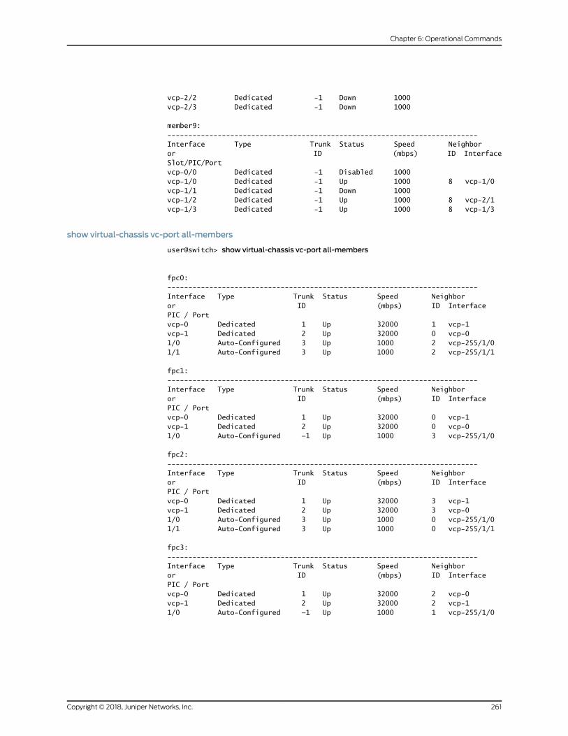
vcp-2/2 Dedicated -1 Down 1000vcp-2/3 Dedicated -1 Down 1000
member9:--------------------------------------------------------------------------Interface Type Trunk Status Speed Neighboror ID (mbps) ID InterfaceSlot/PIC/Portvcp-0/0 Dedicated -1 Disabled 1000vcp-1/0 Dedicated -1 Up 1000 8 vcp-1/0vcp-1/1 Dedicated -1 Down 1000vcp-1/2 Dedicated -1 Up 1000 8 vcp-2/1vcp-1/3 Dedicated -1 Up 1000 8 vcp-1/3
show virtual-chassis vc-port all-members
user@switch> show virtual-chassis vc-port all-members
fpc0:--------------------------------------------------------------------------Interface Type Trunk Status Speed Neighboror ID (mbps) ID InterfacePIC / Portvcp-0 Dedicated 1 Up 32000 1 vcp-1vcp-1 Dedicated 2 Up 32000 0 vcp-01/0 Auto-Configured 3 Up 1000 2 vcp-255/1/01/1 Auto-Configured 3 Up 1000 2 vcp-255/1/1
fpc1:--------------------------------------------------------------------------Interface Type Trunk Status Speed Neighboror ID (mbps) ID InterfacePIC / Portvcp-0 Dedicated 1 Up 32000 0 vcp-1vcp-1 Dedicated 2 Up 32000 0 vcp-01/0 Auto-Configured —1 Up 1000 3 vcp-255/1/0
fpc2:--------------------------------------------------------------------------Interface Type Trunk Status Speed Neighboror ID (mbps) ID InterfacePIC / Portvcp-0 Dedicated 1 Up 32000 3 vcp-1vcp-1 Dedicated 2 Up 32000 3 vcp-01/0 Auto-Configured 3 Up 1000 0 vcp-255/1/01/1 Auto-Configured 3 Up 1000 0 vcp-255/1/1
fpc3: --------------------------------------------------------------------------Interface Type Trunk Status Speed Neighboror ID (mbps) ID InterfacePIC / Portvcp-0 Dedicated 1 Up 32000 2 vcp-0vcp-1 Dedicated 2 Up 32000 2 vcp-1 1/0 Auto-Configured —1 Up 1000 1 vcp-255/1/0
261Copyright © 2018, Juniper Networks, Inc.
Chapter 6: Operational Commands

show virtual-chassis vc-port diagnostics optics
Syntax show virtual-chassis vc-port diagnostics optics<all-members><interface-name><local><membermember-id>
Release Information Command introduced in Junos OS Release 12.2 for EX Series switches.
Command introduced in Junos OSRelease 13.2X51-D20 for Virtual Chassis Fabric (VCF).
Description Display diagnostics data and alarms for Ethernet optical transceivers installed in ports
configured as Virtual Chassis Ports (VCPs) in an EX Series switches. The information
provided by this command is known as digital optical monitoring (DOM) information.
Thresholds that trigger a high alarm, low alarm, high warning, or low warning are set by
the transponder vendors. Generally, a highalarmor lowalarm indicates that a transceiver
is not operating properly. DOM information can be used to diagnose why a transceiver is
not working.
On some EX Series switches, the request virtual-chassis vc-port diagnostics optics
commandmust be entered to run a diagnostic scan before you can gather the show
virtual-chassis vc-port diagnostics optics output.
Options none—Display diagnostics information for transceivers installed in VCPs of all membersof a Virtual Chassis or VCF.
all-members—(Optional) Display diagnostics information for transceivers installed inVCPs of all members of a Virtual Chassis or VCF.
interface-name—(Optional) Display diagnostics information for the transceiver installedin a specified VCP.
local—(Optional) Display diagnostics information for transceivers installed in VCPs onthe switch or external Routing Engine on which this command is entered.
membermember-id—(Optional)Displaydiagnostics information for transceivers installedin VCPs on a specified member of a Virtual Chassis or VCF.
Required PrivilegeLevel
view
RelatedDocumentation
show virtual-chassis vc-port on page 258•
• Installing a Transceiver
• Removing a Transceiver
• Junos OS Ethernet Interfaces Configuration Guide
Copyright © 2018, Juniper Networks, Inc.262
Virtual Chassis Feature Guide for Switches

List of Sample Output show virtual-chassis vc-port diagnostics optics on page 265show virtual-chassis vc-port diagnostics optics (interface-name) on page 270show virtual-chassis vc-port diagnostics optics local on page 272show virtual-chassis vc-port diagnostics optics (membermember-id) on page 274
Output Fields Table22onpage263 lists theoutput fields for the showvirtual-chassisvc-portdiagnostics
optics command. Output fields are listed in the approximate order in which they appear.
Table 22: show virtual-chassis vc-port diagnostics optics Output Fields
Field DescriptionField Name
Displays the FPC slot number.FPC
Displays the name of the VCP.Virtual chassis port
Displays the magnitude of the laser bias power setting current, inmilliamperes (mA).The laserbiasprovidesdirectmodulationof laserdiodesandmodulates currents.
Laser bias current
Displays the laser output power, in milliwatts (mW) and decibels referredto 1.0 mW (dBm).
Laser output power
Displays the temperature, in Celsius and Fahrenheit.Module temperature
Displays the voltage, in Volts.Module voltage
Displays the receiver signal average optical power, in milliwatts (mW) anddecibels referred to 1.0 mW (dBm).
Receiver signal average optical power
Displays whether the laser bias power setting high alarm isOn orOff.Laser bias current high alarm
Displays whether the laser bias power setting low alarm isOn orOff.Laser bias current low alarm
Displays whether the laser bias power setting high warning isOn orOff.Laser bias current high warning
Displays whether the laser bias power setting lowwarning isOn orOff.Laser bias current lowwarning
Displays whether the laser output power high alarm isOn orOff.Laser output power high alarm
Displays whether the laser output power low alarm isOn orOff.Laser output power low alarm
Displays whether the laser output power high warning isOn orOff.Laser output power high warning
Displays whether the laser output power lowwarning isOn orOff.Laser output power lowwarning
Displays whether the module temperature high alarm isOn orOff.Module temperature high alarm
Displays whether the module temperature low alarm isOn orOff.Module temperature low alarm
Displays whether the module temperature high warning isOn orOff.Module temperature high warning
263Copyright © 2018, Juniper Networks, Inc.
Chapter 6: Operational Commands

Table 22: show virtual-chassis vc-port diagnostics optics Output Fields (continued)
Field DescriptionField Name
Displays whether the module temperature lowwarning isOn orOff.Module temperature lowwarning
Displays whether the module voltage high alarm isOn orOff.Module voltage high alarm
Displays whether the module voltage low alarm isOn orOff.Module voltage low alarm
Displays whether the module voltage high warning isOn orOff.Module voltage high warning
Displays whether the module voltage lowwarning isOn orOff.Module voltage lowwarning
Displays whether the receive laser power high alarm isOn orOff.Laser rx power high alarm
Displays whether the receive laser power low alarm isOn orOff.Laser rx power low alarm
Displays whether the receive laser power high warning isOn orOff.Laser rx power high warning
Displays whether the receive laser power lowwarning isOn orOff.Laser rx power lowwarning
Displays thevendor-specified threshold for the laserbias currenthighalarm.Laser bias current high alarm threshold
Displays thevendor-specified threshold for the laserbias current lowalarm.Laser bias current low alarm threshold
Displays the vendor-specified threshold for the laser bias current highwarning.
Laser bias current high warning threshold
Displays the vendor-specified threshold for the laser bias current lowwarning.
Laser bias current lowwarning threshold
Displays the vendor-specified threshold for the laser output power highalarm.
Laser output power high alarm threshold
Displays the vendor-specified threshold for the laser output power lowalarm.
Laser output power low alarm threshold
Displays the vendor-specified threshold for the laser output power highwarning.
Laser output power high warning threshold
Displays the vendor-specified threshold for the laser output power lowwarning.
Laser output power lowwarning threshold
Displays the vendor-specified threshold for the module temperature highalarm.
Module temperature high alarm threshold
Displays the vendor-specified threshold for the module temperature lowalarm.
Module temperature low alarm threshold
Displays the vendor-specified threshold for the module temperature highwarning.
Module temperature high warning threshold
Copyright © 2018, Juniper Networks, Inc.264
Virtual Chassis Feature Guide for Switches

Table 22: show virtual-chassis vc-port diagnostics optics Output Fields (continued)
Field DescriptionField Name
Displays the vendor-specified threshold for the module temperature lowwarning.
Module temperature lowwarning threshold
Displays the vendor-specified threshold for themodule voltage high alarm.Module voltage high alarm threshold
Displays the vendor-specified threshold for the module voltage low alarm.Module voltage low alarm threshold
Displays thevendor-specified threshold for themodulevoltagehighwarning.Module voltage high warning threshold
Displays thevendor-specified threshold for themodulevoltage lowwarning.Module voltage lowwarning threshold
Displays the vendor-specified threshold for the laser rx power high alarm.Laser rx power high alarm threshold
Displays the vendor-specified threshold for the laser rx power low alarm.Laser rx power low alarm threshold
Displays the vendor-specified threshold for the laser rx power highwarning.Laser rx power high warning threshold
Displays the vendor-specified threshold for the laser rx power lowwarning.Laser rx power lowwarning threshold
Sample Output
show virtual-chassis vc-port diagnostics optics
user@switch> show virtual-chassis vc-port diagnostics opticsfpc0:--------------------------------------------------------------------------Virtual chassis port: vcp-0 Optical diagnostics : N/AVirtual chassis port: vcp-1 Optical diagnostics : N/A
fpc1:--------------------------------------------------------------------------Virtual chassis port: vcp-0 Optical diagnostics : N/AVirtual chassis port: vcp-1 Optical diagnostics : N/A
fpc2:--------------------------------------------------------------------------Virtual chassis port: vcp-2/0 Optical diagnostics : N/AVirtual chassis port: vcp-2/1 Optical diagnostics : N/AVirtual chassis port: vcp-255/0/14 Optical diagnostics : N/AVirtual chassis port: vcp-255/0/15 Optical diagnostics : N/AVirtual chassis port: vcp-255/0/24 Laser bias current : 4.130 mA Laser output power : 0.2450 mW / -6.11 dBm Module temperature : 32 degrees C / 90 degrees F
265Copyright © 2018, Juniper Networks, Inc.
Chapter 6: Operational Commands

Module voltage : 3.3530 V Receiver signal average optical power : 0.0971 mW / -10.13 dBm Laser bias current high alarm : Off Laser bias current low alarm : Off Laser bias current high warning : Off Laser bias current low warning : Off Laser output power high alarm : Off Laser output power low alarm : Off Laser output power high warning : Off Laser output power low warning : Off Module temperature high alarm : Off Module temperature low alarm : Off Module temperature high warning : Off Module temperature low warning : Off Module voltage high alarm : Off Module voltage low alarm : Off Module voltage high warning : Off Module voltage low warning : Off Laser rx power high alarm : Off Laser rx power low alarm : Off Laser rx power high warning : Off Laser rx power low warning : Off Laser bias current high alarm threshold : 14.998 mA Laser bias current low alarm threshold : 0.998 mA Laser bias current high warning threshold : 14.000 mA Laser bias current low warning threshold : 1.198 mA Laser output power high alarm threshold : 0.7940 mW / -1.00 dBm Laser output power low alarm threshold : 0.0790 mW / -11.02 dBm Laser output power high warning threshold : 0.6300 mW / -2.01 dBm Laser output power low warning threshold : 0.0990 mW / -10.04 dBm Module temperature high alarm threshold : 85 degrees C / 185 degrees F Module temperature low alarm threshold : -10 degrees C / 14 degrees F Module temperature high warning threshold : 80 degrees C / 176 degrees F Module temperature low warning threshold : -5 degrees C / 23 degrees F Module voltage high alarm threshold : 3.600 V Module voltage low alarm threshold : 3.000 V Module voltage high warning threshold : 3.499 V Module voltage low warning threshold : 3.099 V Laser rx power high alarm threshold : 1.5848 mW / 2.00 dBm Laser rx power low alarm threshold : 0.0100 mW / -20.00 dBm Laser rx power high warning threshold : 1.2589 mW / 1.00 dBm Laser rx power low warning threshold : 0.0125 mW / -19.03 dBmVirtual chassis port: vcp-255/0/3 Laser bias current : 5.428 mA Laser output power : 0.4760 mW / -3.22 dBm Module temperature : 28 degrees C / 83 degrees F Module voltage : 3.3440 V Receiver signal average optical power : 0.4002 mW / -3.98 dBm Laser bias current high alarm : Off Laser bias current low alarm : Off Laser bias current high warning : Off Laser bias current low warning : Off Laser output power high alarm : Off Laser output power low alarm : Off Laser output power high warning : Off Laser output power low warning : Off Module temperature high alarm : Off Module temperature low alarm : Off Module temperature high warning : Off Module temperature low warning : Off Module voltage high alarm : Off
Copyright © 2018, Juniper Networks, Inc.266
Virtual Chassis Feature Guide for Switches

Module voltage low alarm : Off Module voltage high warning : Off Module voltage low warning : Off Laser rx power high alarm : Off Laser rx power low alarm : Off Laser rx power high warning : Off Laser rx power low warning : Off Laser bias current high alarm threshold : 10.500 mA Laser bias current low alarm threshold : 2.000 mA Laser bias current high warning threshold : 9.000 mA Laser bias current low warning threshold : 2.500 mA Laser output power high alarm threshold : 1.4120 mW / 1.50 dBm Laser output power low alarm threshold : 0.0740 mW / -11.31 dBm Laser output power high warning threshold : 0.7070 mW / -1.51 dBm Laser output power low warning threshold : 0.1860 mW / -7.30 dBm Module temperature high alarm threshold : 75 degrees C / 167 degrees F Module temperature low alarm threshold : -5 degrees C / 23 degrees F Module temperature high warning threshold : 70 degrees C / 158 degrees F Module temperature low warning threshold : 0 degrees C / 32 degrees F Module voltage high alarm threshold : 3.630 V Module voltage low alarm threshold : 2.970 V Module voltage high warning threshold : 3.465 V Module voltage low warning threshold : 3.135 V Laser rx power high alarm threshold : 1.5849 mW / 2.00 dBm Laser rx power low alarm threshold : 0.0407 mW / -13.90 dBm Laser rx power high warning threshold : 0.7943 mW / -1.00 dBm Laser rx power low warning threshold : 0.1023 mW / -9.90 dBm
fpc3:--------------------------------------------------------------------------Virtual chassis port: vcp-255/0/2 Laser bias current : 7.876 mA Laser output power : 0.5330 mW / -2.73 dBm Module temperature : 26 degrees C / 78 degrees F Module voltage : 3.3060 V Receiver signal average optical power : 0.4885 mW / -3.11 dBm Laser bias current high alarm : Off Laser bias current low alarm : Off Laser bias current high warning : Off Laser bias current low warning : Off Laser output power high alarm : Off Laser output power low alarm : Off Laser output power high warning : Off Laser output power low warning : Off Module temperature high alarm : Off Module temperature low alarm : Off Module temperature high warning : Off Module temperature low warning : Off Module voltage high alarm : Off Module voltage low alarm : Off Module voltage high warning : Off Module voltage low warning : Off Laser rx power high alarm : Off Laser rx power low alarm : Off Laser rx power high warning : Off Laser rx power low warning : Off Laser bias current high alarm threshold : 14.500 mA Laser bias current low alarm threshold : 3.500 mA Laser bias current high warning threshold : 14.500 mA Laser bias current low warning threshold : 3.500 mA Laser output power high alarm threshold : 1.8620 mW / 2.70 dBm
267Copyright © 2018, Juniper Networks, Inc.
Chapter 6: Operational Commands

Laser output power low alarm threshold : 0.0740 mW / -11.31 dBm Laser output power high warning threshold : 0.7410 mW / -1.30 dBm Laser output power low warning threshold : 0.1860 mW / -7.30 dBm Module temperature high alarm threshold : 75 degrees C / 167 degrees F Module temperature low alarm threshold : -5 degrees C / 23 degrees F Module temperature high warning threshold : 70 degrees C / 158 degrees F Module temperature low warning threshold : 0 degrees C / 32 degrees F Module voltage high alarm threshold : 3.630 V Module voltage low alarm threshold : 2.970 V Module voltage high warning threshold : 3.465 V Module voltage low warning threshold : 3.135 V Laser rx power high alarm threshold : 1.9952 mW / 3.00 dBm Laser rx power low alarm threshold : 0.0407 mW / -13.90 dBm Laser rx power high warning threshold : 0.7943 mW / -1.00 dBm Laser rx power low warning threshold : 0.1023 mW / -9.90 dBmVirtual chassis port: vcp-255/0/3 Laser bias current : 5.052 mA Laser output power : 0.5030 mW / -2.98 dBm Module temperature : 24 degrees C / 75 degrees F Module voltage : 3.2890 V Receiver signal average optical power : 0.5028 mW / -2.99 dBm Laser bias current high alarm : Off Laser bias current low alarm : Off Laser bias current high warning : Off Laser bias current low warning : Off Laser output power high alarm : Off Laser output power low alarm : Off Laser output power high warning : Off Laser output power low warning : Off Module temperature high alarm : Off Module temperature low alarm : Off Module temperature high warning : Off Module temperature low warning : Off Module voltage high alarm : Off Module voltage low alarm : Off Module voltage high warning : Off Module voltage low warning : Off Laser rx power high alarm : Off Laser rx power low alarm : Off Laser rx power high warning : Off Laser rx power low warning : Off Laser bias current high alarm threshold : 10.500 mA Laser bias current low alarm threshold : 2.000 mA Laser bias current high warning threshold : 9.000 mA Laser bias current low warning threshold : 2.500 mA Laser output power high alarm threshold : 1.4120 mW / 1.50 dBm Laser output power low alarm threshold : 0.0740 mW / -11.31 dBm Laser output power high warning threshold : 0.7070 mW / -1.51 dBm Laser output power low warning threshold : 0.1860 mW / -7.30 dBm Module temperature high alarm threshold : 75 degrees C / 167 degrees F Module temperature low alarm threshold : -5 degrees C / 23 degrees F Module temperature high warning threshold : 70 degrees C / 158 degrees F Module temperature low warning threshold : 0 degrees C / 32 degrees F Module voltage high alarm threshold : 3.630 V Module voltage low alarm threshold : 2.970 V Module voltage high warning threshold : 3.465 V Module voltage low warning threshold : 3.135 V Laser rx power high alarm threshold : 1.5849 mW / 2.00 dBm Laser rx power low alarm threshold : 0.0407 mW / -13.90 dBm Laser rx power high warning threshold : 0.7943 mW / -1.00 dBm Laser rx power low warning threshold : 0.1023 mW / -9.90 dBm
Copyright © 2018, Juniper Networks, Inc.268
Virtual Chassis Feature Guide for Switches

Virtual chassis port: vcp-255/0/4 Laser bias current : 7.978 mA Laser output power : 0.5460 mW / -2.63 dBm Module temperature : 24 degrees C / 76 degrees F Module voltage : 3.3060 V Receiver signal average optical power : 0.6305 mW / -2.00 dBm Laser bias current high alarm : Off Laser bias current low alarm : Off Laser bias current high warning : Off Laser bias current low warning : Off Laser output power high alarm : Off Laser output power low alarm : Off Laser output power high warning : Off Laser output power low warning : Off Module temperature high alarm : Off Module temperature low alarm : Off Module temperature high warning : Off Module temperature low warning : Off Module voltage high alarm : Off Module voltage low alarm : Off Module voltage high warning : Off Module voltage low warning : Off Laser rx power high alarm : Off Laser rx power low alarm : Off Laser rx power high warning : Off Laser rx power low warning : Off Laser bias current high alarm threshold : 14.500 mA Laser bias current low alarm threshold : 3.500 mA Laser bias current high warning threshold : 14.500 mA Laser bias current low warning threshold : 3.500 mA Laser output power high alarm threshold : 1.8620 mW / 2.70 dBm Laser output power low alarm threshold : 0.0740 mW / -11.31 dBm Laser output power high warning threshold : 0.7410 mW / -1.30 dBm Laser output power low warning threshold : 0.1860 mW / -7.30 dBm Module temperature high alarm threshold : 75 degrees C / 167 degrees F Module temperature low alarm threshold : -5 degrees C / 23 degrees F Module temperature high warning threshold : 70 degrees C / 158 degrees F Module temperature low warning threshold : 0 degrees C / 32 degrees F Module voltage high alarm threshold : 3.630 V Module voltage low alarm threshold : 2.970 V Module voltage high warning threshold : 3.465 V Module voltage low warning threshold : 3.135 V Laser rx power high alarm threshold : 1.9952 mW / 3.00 dBm Laser rx power low alarm threshold : 0.0407 mW / -13.90 dBm Laser rx power high warning threshold : 0.7943 mW / -1.00 dBm Laser rx power low warning threshold : 0.1023 mW / -9.90 dBmfpc4:--------------------------------------------------------------------------Virtual chassis port: vcp-0 Optical diagnostics : N/AVirtual chassis port: vcp-1 Optical diagnostics : N/AVirtual chassis port: vcp-255/0/4 Laser bias current : 7.860 mA Laser output power : 0.5370 mW / -2.70 dBm Module temperature : 24 degrees C / 75 degrees F Module voltage : 3.2920 V Receiver signal average optical power : 0.6271 mW / -2.03 dBm Laser bias current high alarm : Off Laser bias current low alarm : Off Laser bias current high warning : Off
269Copyright © 2018, Juniper Networks, Inc.
Chapter 6: Operational Commands

Laser bias current low warning : Off Laser output power high alarm : Off Laser output power low alarm : Off Laser output power high warning : Off Laser output power low warning : Off Module temperature high alarm : Off Module temperature low alarm : Off Module temperature high warning : Off Module temperature low warning : Off Module voltage high alarm : Off Module voltage low alarm : Off Module voltage high warning : Off Module voltage low warning : Off Laser rx power high alarm : Off Laser rx power low alarm : Off Laser rx power high warning : Off Laser rx power low warning : Off Laser bias current high alarm threshold : 14.500 mA Laser bias current low alarm threshold : 3.500 mA Laser bias current high warning threshold : 14.500 mA Laser bias current low warning threshold : 3.500 mA Laser output power high alarm threshold : 1.8620 mW / 2.70 dBm Laser output power low alarm threshold : 0.0740 mW / -11.31 dBm Laser output power high warning threshold : 0.7410 mW / -1.30 dBm Laser output power low warning threshold : 0.1860 mW / -7.30 dBm Module temperature high alarm threshold : 75 degrees C / 167 degrees F Module temperature low alarm threshold : -5 degrees C / 23 degrees F Module temperature high warning threshold : 70 degrees C / 158 degrees F Module temperature low warning threshold : 0 degrees C / 32 degrees F Module voltage high alarm threshold : 3.630 V Module voltage low alarm threshold : 2.970 V Module voltage high warning threshold : 3.465 V Module voltage low warning threshold : 3.135 V Laser rx power high alarm threshold : 1.9952 mW / 3.00 dBm Laser rx power low alarm threshold : 0.0407 mW / -13.90 dBm Laser rx power high warning threshold : 0.7943 mW / -1.00 dBm Laser rx power low warning threshold : 0.1023 mW / -9.90 dBm
show virtual-chassis vc-port diagnostics optics (interface-name)
user@external-routing-engine> showvirtual-chassisvc-portdiagnosticsopticsvcp-255/0/3fpc0:--------------------------------------------------------------------------
fpc1:--------------------------------------------------------------------------
fpc2:--------------------------------------------------------------------------Virtual chassis port: vcp-255/0/3 Laser bias current : 5.448 mA Laser output power : 0.4770 mW / -3.21 dBm Module temperature : 28 degrees C / 82 degrees F Module voltage : 3.3450 V Receiver signal average optical power : 0.3973 mW / -4.01 dBm Laser bias current high alarm : Off Laser bias current low alarm : Off Laser bias current high warning : Off Laser bias current low warning : Off Laser output power high alarm : Off Laser output power low alarm : Off
Copyright © 2018, Juniper Networks, Inc.270
Virtual Chassis Feature Guide for Switches

Laser output power high warning : Off Laser output power low warning : Off Module temperature high alarm : Off Module temperature low alarm : Off Module temperature high warning : Off Module temperature low warning : Off Module voltage high alarm : Off Module voltage low alarm : Off Module voltage high warning : Off Module voltage low warning : Off Laser rx power high alarm : Off Laser rx power low alarm : Off Laser rx power high warning : Off Laser rx power low warning : Off Laser bias current high alarm threshold : 10.500 mA Laser bias current low alarm threshold : 2.000 mA Laser bias current high warning threshold : 9.000 mA Laser bias current low warning threshold : 2.500 mA Laser output power high alarm threshold : 1.4120 mW / 1.50 dBm Laser output power low alarm threshold : 0.0740 mW / -11.31 dBm Laser output power high warning threshold : 0.7070 mW / -1.51 dBm Laser output power low warning threshold : 0.1860 mW / -7.30 dBm Module temperature high alarm threshold : 75 degrees C / 167 degrees F Module temperature low alarm threshold : -5 degrees C / 23 degrees F Module temperature high warning threshold : 70 degrees C / 158 degrees F Module temperature low warning threshold : 0 degrees C / 32 degrees F Module voltage high alarm threshold : 3.630 V Module voltage low alarm threshold : 2.970 V Module voltage high warning threshold : 3.465 V Module voltage low warning threshold : 3.135 V Laser rx power high alarm threshold : 1.5849 mW / 2.00 dBm Laser rx power low alarm threshold : 0.0407 mW / -13.90 dBm Laser rx power high warning threshold : 0.7943 mW / -1.00 dBm Laser rx power low warning threshold : 0.1023 mW / -9.90 dBm
fpc3:--------------------------------------------------------------------------Virtual chassis port: vcp-255/0/3 Laser bias current : 5.040 mA Laser output power : 0.5020 mW / -2.99 dBm Module temperature : 24 degrees C / 74 degrees F Module voltage : 3.2870 V Receiver signal average optical power : 0.5073 mW / -2.95 dBm Laser bias current high alarm : Off Laser bias current low alarm : Off Laser bias current high warning : Off Laser bias current low warning : Off Laser output power high alarm : Off Laser output power low alarm : Off Laser output power high warning : Off Laser output power low warning : Off Module temperature high alarm : Off Module temperature low alarm : Off Module temperature high warning : Off Module temperature low warning : Off Module voltage high alarm : Off Module voltage low alarm : Off Module voltage high warning : Off Module voltage low warning : Off Laser rx power high alarm : Off Laser rx power low alarm : Off
271Copyright © 2018, Juniper Networks, Inc.
Chapter 6: Operational Commands
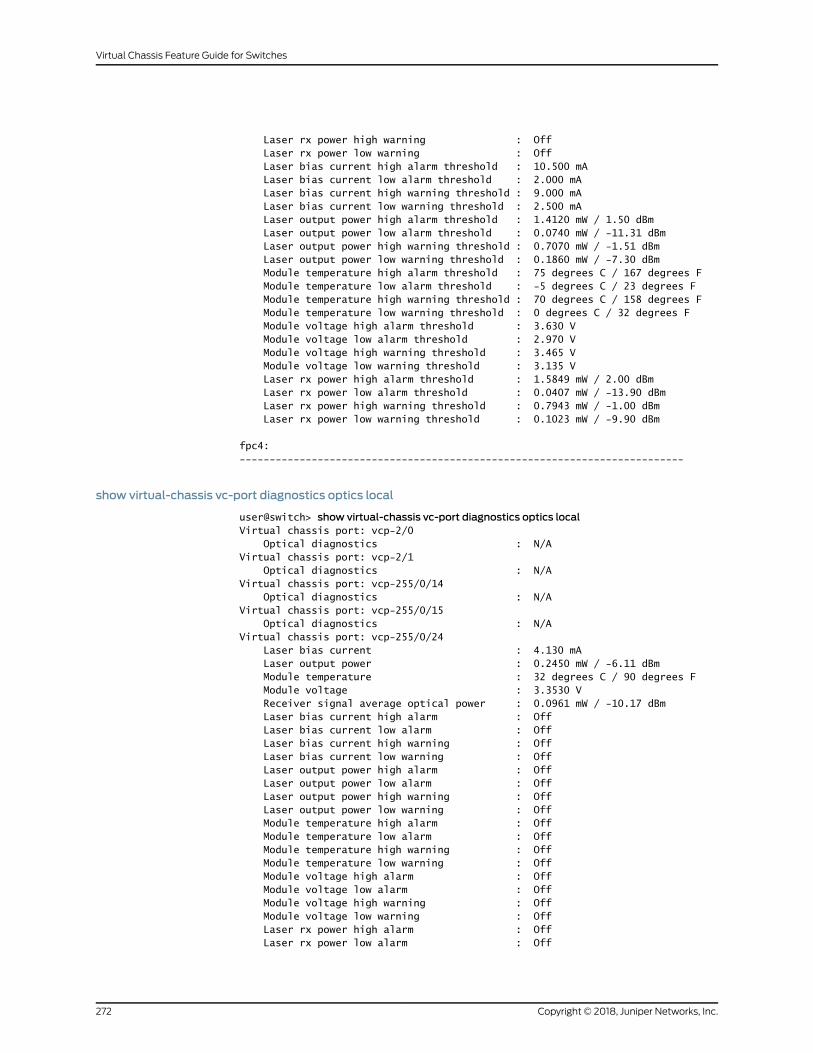
Laser rx power high warning : Off Laser rx power low warning : Off Laser bias current high alarm threshold : 10.500 mA Laser bias current low alarm threshold : 2.000 mA Laser bias current high warning threshold : 9.000 mA Laser bias current low warning threshold : 2.500 mA Laser output power high alarm threshold : 1.4120 mW / 1.50 dBm Laser output power low alarm threshold : 0.0740 mW / -11.31 dBm Laser output power high warning threshold : 0.7070 mW / -1.51 dBm Laser output power low warning threshold : 0.1860 mW / -7.30 dBm Module temperature high alarm threshold : 75 degrees C / 167 degrees F Module temperature low alarm threshold : -5 degrees C / 23 degrees F Module temperature high warning threshold : 70 degrees C / 158 degrees F Module temperature low warning threshold : 0 degrees C / 32 degrees F Module voltage high alarm threshold : 3.630 V Module voltage low alarm threshold : 2.970 V Module voltage high warning threshold : 3.465 V Module voltage low warning threshold : 3.135 V Laser rx power high alarm threshold : 1.5849 mW / 2.00 dBm Laser rx power low alarm threshold : 0.0407 mW / -13.90 dBm Laser rx power high warning threshold : 0.7943 mW / -1.00 dBm Laser rx power low warning threshold : 0.1023 mW / -9.90 dBm
fpc4:--------------------------------------------------------------------------
show virtual-chassis vc-port diagnostics optics local
user@switch> show virtual-chassis vc-port diagnostics optics localVirtual chassis port: vcp-2/0 Optical diagnostics : N/AVirtual chassis port: vcp-2/1 Optical diagnostics : N/AVirtual chassis port: vcp-255/0/14 Optical diagnostics : N/AVirtual chassis port: vcp-255/0/15 Optical diagnostics : N/AVirtual chassis port: vcp-255/0/24 Laser bias current : 4.130 mA Laser output power : 0.2450 mW / -6.11 dBm Module temperature : 32 degrees C / 90 degrees F Module voltage : 3.3530 V Receiver signal average optical power : 0.0961 mW / -10.17 dBm Laser bias current high alarm : Off Laser bias current low alarm : Off Laser bias current high warning : Off Laser bias current low warning : Off Laser output power high alarm : Off Laser output power low alarm : Off Laser output power high warning : Off Laser output power low warning : Off Module temperature high alarm : Off Module temperature low alarm : Off Module temperature high warning : Off Module temperature low warning : Off Module voltage high alarm : Off Module voltage low alarm : Off Module voltage high warning : Off Module voltage low warning : Off Laser rx power high alarm : Off Laser rx power low alarm : Off
Copyright © 2018, Juniper Networks, Inc.272
Virtual Chassis Feature Guide for Switches

Laser rx power high warning : Off Laser rx power low warning : Off Laser bias current high alarm threshold : 14.998 mA Laser bias current low alarm threshold : 0.998 mA Laser bias current high warning threshold : 14.000 mA Laser bias current low warning threshold : 1.198 mA Laser output power high alarm threshold : 0.7940 mW / -1.00 dBm Laser output power low alarm threshold : 0.0790 mW / -11.02 dBm Laser output power high warning threshold : 0.6300 mW / -2.01 dBm Laser output power low warning threshold : 0.0990 mW / -10.04 dBm Module temperature high alarm threshold : 85 degrees C / 185 degrees F Module temperature low alarm threshold : -10 degrees C / 14 degrees F Module temperature high warning threshold : 80 degrees C / 176 degrees F Module temperature low warning threshold : -5 degrees C / 23 degrees F Module voltage high alarm threshold : 3.600 V Module voltage low alarm threshold : 3.000 V Module voltage high warning threshold : 3.499 V Module voltage low warning threshold : 3.099 V Laser rx power high alarm threshold : 1.5848 mW / 2.00 dBm Laser rx power low alarm threshold : 0.0100 mW / -20.00 dBm Laser rx power high warning threshold : 1.2589 mW / 1.00 dBm Laser rx power low warning threshold : 0.0125 mW / -19.03 dBmVirtual chassis port: vcp-255/0/3 Laser bias current : 5.426 mA Laser output power : 0.4760 mW / -3.22 dBm Module temperature : 28 degrees C / 83 degrees F Module voltage : 3.3450 V Receiver signal average optical power : 0.3955 mW / -4.03 dBm Laser bias current high alarm : Off Laser bias current low alarm : Off Laser bias current high warning : Off Laser bias current low warning : Off Laser output power high alarm : Off Laser output power low alarm : Off Laser output power high warning : Off Laser output power low warning : Off Module temperature high alarm : Off Module temperature low alarm : Off Module temperature high warning : Off Module temperature low warning : Off Module voltage high alarm : Off Module voltage low alarm : Off Module voltage high warning : Off Module voltage low warning : Off Laser rx power high alarm : Off Laser rx power low alarm : Off Laser rx power high warning : Off Laser rx power low warning : Off Laser bias current high alarm threshold : 10.500 mA Laser bias current low alarm threshold : 2.000 mA Laser bias current high warning threshold : 9.000 mA Laser bias current low warning threshold : 2.500 mA Laser output power high alarm threshold : 1.4120 mW / 1.50 dBm Laser output power low alarm threshold : 0.0740 mW / -11.31 dBm Laser output power high warning threshold : 0.7070 mW / -1.51 dBm Laser output power low warning threshold : 0.1860 mW / -7.30 dBm Module temperature high alarm threshold : 75 degrees C / 167 degrees F Module temperature low alarm threshold : -5 degrees C / 23 degrees F Module temperature high warning threshold : 70 degrees C / 158 degrees F Module temperature low warning threshold : 0 degrees C / 32 degrees F Module voltage high alarm threshold : 3.630 V
273Copyright © 2018, Juniper Networks, Inc.
Chapter 6: Operational Commands

Module voltage low alarm threshold : 2.970 V Module voltage high warning threshold : 3.465 V Module voltage low warning threshold : 3.135 V Laser rx power high alarm threshold : 1.5849 mW / 2.00 dBm Laser rx power low alarm threshold : 0.0407 mW / -13.90 dBm Laser rx power high warning threshold : 0.7943 mW / -1.00 dBm Laser rx power low warning threshold : 0.1023 mW / -9.90 dBm
show virtual-chassis vc-port diagnostics optics (membermember-id)
user@switch> show virtual-chassis vc-port diagnostics opticsmember 2fpc2:--------------------------------------------------------------------------Virtual chassis port: vcp-2/0 Optical diagnostics : N/AVirtual chassis port: vcp-2/1 Optical diagnostics : N/AVirtual chassis port: vcp-255/0/14 Optical diagnostics : N/AVirtual chassis port: vcp-255/0/15 Optical diagnostics : N/AVirtual chassis port: vcp-255/0/24 Laser bias current : 4.130 mA Laser output power : 0.2450 mW / -6.11 dBm Module temperature : 31 degrees C / 88 degrees F Module voltage : 3.3530 V Receiver signal average optical power : 0.0961 mW / -10.17 dBm Laser bias current high alarm : Off Laser bias current low alarm : Off Laser bias current high warning : Off Laser bias current low warning : Off Laser output power high alarm : Off Laser output power low alarm : Off Laser output power high warning : Off Laser output power low warning : Off Module temperature high alarm : Off Module temperature low alarm : Off Module temperature high warning : Off Module temperature low warning : Off Module voltage high alarm : Off Module voltage low alarm : Off Module voltage high warning : Off Module voltage low warning : Off Laser rx power high alarm : Off Laser rx power low alarm : Off Laser rx power high warning : Off Laser rx power low warning : Off Laser bias current high alarm threshold : 14.998 mA Laser bias current low alarm threshold : 0.998 mA Laser bias current high warning threshold : 14.000 mA Laser bias current low warning threshold : 1.198 mA Laser output power high alarm threshold : 0.7940 mW / -1.00 dBm Laser output power low alarm threshold : 0.0790 mW / -11.02 dBm Laser output power high warning threshold : 0.6300 mW / -2.01 dBm Laser output power low warning threshold : 0.0990 mW / -10.04 dBm Module temperature high alarm threshold : 85 degrees C / 185 degrees F Module temperature low alarm threshold : -10 degrees C / 14 degrees F Module temperature high warning threshold : 80 degrees C / 176 degrees F Module temperature low warning threshold : -5 degrees C / 23 degrees F Module voltage high alarm threshold : 3.600 V
Copyright © 2018, Juniper Networks, Inc.274
Virtual Chassis Feature Guide for Switches

Module voltage low alarm threshold : 3.000 V Module voltage high warning threshold : 3.499 V Module voltage low warning threshold : 3.099 V Laser rx power high alarm threshold : 1.5848 mW / 2.00 dBm Laser rx power low alarm threshold : 0.0100 mW / -20.00 dBm Laser rx power high warning threshold : 1.2589 mW / 1.00 dBm Laser rx power low warning threshold : 0.0125 mW / -19.03 dBmVirtual chassis port: vcp-255/0/3 Laser bias current : 5.418 mA Laser output power : 0.4770 mW / -3.21 dBm Module temperature : 28 degrees C / 83 degrees F Module voltage : 3.3450 V Receiver signal average optical power : 0.3964 mW / -4.02 dBm Laser bias current high alarm : Off Laser bias current low alarm : Off Laser bias current high warning : Off Laser bias current low warning : Off Laser output power high alarm : Off Laser output power low alarm : Off Laser output power high warning : Off Laser output power low warning : Off Module temperature high alarm : Off Module temperature low alarm : Off Module temperature high warning : Off Module temperature low warning : Off Module voltage high alarm : Off Module voltage low alarm : Off Module voltage high warning : Off Module voltage low warning : Off Laser rx power high alarm : Off Laser rx power low alarm : Off Laser rx power high warning : Off Laser rx power low warning : Off Laser bias current high alarm threshold : 10.500 mA Laser bias current low alarm threshold : 2.000 mA Laser bias current high warning threshold : 9.000 mA Laser bias current low warning threshold : 2.500 mA Laser output power high alarm threshold : 1.4120 mW / 1.50 dBm Laser output power low alarm threshold : 0.0740 mW / -11.31 dBm Laser output power high warning threshold : 0.7070 mW / -1.51 dBm Laser output power low warning threshold : 0.1860 mW / -7.30 dBm Module temperature high alarm threshold : 75 degrees C / 167 degrees F Module temperature low alarm threshold : -5 degrees C / 23 degrees F Module temperature high warning threshold : 70 degrees C / 158 degrees F Module temperature low warning threshold : 0 degrees C / 32 degrees F Module voltage high alarm threshold : 3.630 V Module voltage low alarm threshold : 2.970 V Module voltage high warning threshold : 3.465 V Module voltage low warning threshold : 3.135 V Laser rx power high alarm threshold : 1.5849 mW / 2.00 dBm Laser rx power low alarm threshold : 0.0407 mW / -13.90 dBm Laser rx power high warning threshold : 0.7943 mW / -1.00 dBm Laser rx power low warning threshold : 0.1023 mW / -9.90 dBm
275Copyright © 2018, Juniper Networks, Inc.
Chapter 6: Operational Commands

show virtual-chassis vc-port statistics
Syntax show virtual-chassis vc-port statistics<all-members><brief | detail | extensive ><interface-name><local><membermember-id>
Release Information Command introduced in Junos OS Release 9.0 for EX Series switches.
Theoptionsall-members,brief,detail,extensive, and localwereadded in JunosOSRelease
9.3 for EX Series switches.
Command introduced in Junos OS Release 13.2X50-D15 for the QFX Series.
Command introduced in Junos OSRelease 13.2X51-D20 for Virtual Chassis Fabric (VCF).
Description Display the traffic statistics collected on Virtual Chassis ports (VCPs).
Options none—Display traffic statistics for VCPs of all members of a Virtual Chassis or VCF.
brief | detail | extensive—(Optional) Display the specified level of output. Using the briefoption is equivalent to entering the command with no options (the default). The
detail and extensive options provide identical displays.
all-members—(Optional) Display traffic statistics for VCPs of all members of a VirtualChassis or VCF
interface-name—(Optional) Display traffic statistics for the specified VCP.
local—(Optional) Display traffic statistics for VCPs on the switch or external RoutingEngine on which this command is entered.
membermember-id—(Optional) Display traffic statistics for VCPs on the specifiedmember of a Virtual Chassis or VCF.
Required PrivilegeLevel
view
RelatedDocumentation
clear virtual-chassis vc-port statistics on page 192•
• show virtual-chassis vc-port on page 258
• Monitoring the Virtual Chassis Status and Statistics on EX Series Virtual Chassis
• Verifying Virtual Chassis Ports in an EX8200 Virtual Chassis
List of Sample Output show virtual-chassis vc-port statistics on page 279show virtual-chassis vc-port statistics (EX8200 Virtual Chassis) on page 280show virtual-chassis vc-port statistics brief on page 280show virtual-chassis vc-port statistics extensive on page 280
Copyright © 2018, Juniper Networks, Inc.276
Virtual Chassis Feature Guide for Switches

show virtual-chassis vc-port statisticsmember 0 on page 282
Output Fields Table 22 on page 263 lists the output fields for the show virtual-chassis vc-port statistics
command. Output fields are listed in the approximate order in which they appear.
Table 23: show virtual-chassis vc-port statistics Output Fields
Level of OutputField DescriptionField Name
All levels(All Virtual Chassis except EX8200 Virtual Chassis.VCF) ID of the Virtual Chassis member. The FPCnumber is the same as themember ID.
fpcnumber
All levels(EX8200 Virtual Chassis only) Member ID of theVirtual Chassis member.
member number
briefVCP name.Interface
brief,member, noneNumber of octets and packets received on the VCP.InputOctets/Packets
brief,member, noneNumber of octets and packets transmitted on theVCP.
OutputOctets/Packets
All levelsMember ID of the master Routing Engine.master: number
detail, extensiveVCP for which RX (Receive) statistics,TX (Transmit)statistics, or both are reported by the VCP subsystemduringasampling interval—since thestatisticscounterwas last cleared.
Port
detail, extensiveTotal number of octets received and transmitted onthe VCP.
Total octets
detail, extensiveTotal number of packets received and transmitted onthe VCP.
Total packets
detail, extensiveNumber of unicast packets received and transmittedon the VCP.
Unicast packets
detail, extensiveNumber of broadcast packets received andtransmitted on the VCP.
Broadcast packets
detail, extensiveNumberofmulticastpackets receivedandtransmittedon the VCP.
Multicast packets
detail, extensiveNumber of media access control (MAC) controlframes received and transmitted on the VCP.
MAC control frames
277Copyright © 2018, Juniper Networks, Inc.
Chapter 6: Operational Commands

Table 23: show virtual-chassis vc-port statistics Output Fields (continued)
Level of OutputField DescriptionField Name
detail, extensiveNumber of packets received on the VCP that had alength—excluding framing bits, but including framecheck sequence (FCS) octets—of between 64 and1518 octets, inclusive, and had one of the followingerrors:
• Invalid FCSwith an integral number of octets (FCSerror)
• Invalid FCS with a nonintegral number of octets(alignment error)
CRCalignmenterrors
detail, extensiveNumber of packets received on the VCP that werelonger than 1518 octets (excluding framing bits, butincludingFCSoctets)butwereotherwisewell formed.
Oversize packets
detail, extensiveNumber of packets received on the VCP that wereshorter than 64 octets (excluding framing bits butincluding FCS octets) and were otherwise wellformed..
Undersize packets
detail, extensiveNumber of packets received on the VCP that werelonger than 1518 octets—excluding framing bits, butincludingFCSoctets—and thathadeitheranFCSerroror an alignment error.
NOTE: This definition of jabber is different from thedefinition in IEEE-802.3 section8.2.1.5 (10Base5)andsection 10.3.1.4 (10Base2). These documents definejabber as the condition in which any packet exceeds20ms. Theallowed range todetect jabber is between20ms and 150ms.
Jabber packets
detail, extensiveNumber of packets received on the VCP that wereshorter than 64 octets (excluding framing bits, butincluding FCS octets), and had either an FCS error oran alignment error.
Fragment frames normally increment because bothrunts (which are normal occurrences caused bycollisions) and noise hits are counted.
Fragments received
detail, extensiveNumber of outbound packets received on the VCPthat could not be transmitted because of errors.
Ifout errors
detail, extensiveNumber of outbound packets received on the VCPthat were dropped, rather than being encapsulatedand sent out of the switch as fragments. The packetdrop counter is incremented if a temporary shortageof packet memory causes packet fragmentation tofail.
Packet drop events
detail, extensiveNumber of packets received on the VCP (includinginvalid packets) that were 64 octets in length(excluding framing bits, but including FCS octets).
64 octets frames
Copyright © 2018, Juniper Networks, Inc.278
Virtual Chassis Feature Guide for Switches

Table 23: show virtual-chassis vc-port statistics Output Fields (continued)
Level of OutputField DescriptionField Name
detail, extensiveNumber of packets received on the VCP (includinginvalid packets) thatwere between65 and 127 octetsin length, inclusive (excluding framing bits, butincluding FCS octets).
65–127octets frames
detail, extensiveNumber of packets received on the VCP (includinginvalidpackets) thatwerebetween 128and255octetsin length, inclusive (excluding framing bits, butincluding FCS octets).
128–255 octetsframes
detail, extensiveNumber of packets received on the VCP (includinginvalidpackets) thatwerebetween256and511 octetsin length, inclusive (excluding framing bits, butincluding FCS octets).
256–511 octetsframes
detail, extensiveNumber of packets received on the VCP (includinginvalid packets) that were between 512 and1023 octets in length, inclusive (excluding framingbits, but including FCS octets).
512–1023 octetsframes
detail, extensiveNumber of packets received on the VCP (includinginvalid packets) that were between 1024 and1518octets in length, inclusive (excluding framingbits,but including FCS octets).
1024–1518 octetsframes
detail, extensiveNumber of packets per second received andtransmitted on the VCP.
Rate packets persecond
detail, extensiveNumberofbytesper second receivedand transmittedon the VCP.
Rate bytes persecond
Sample Output
show virtual-chassis vc-port statistics
user@switch> show virtual-chassis vc-port statisticsfpc0:--------------------------------------------------------------------------Interface Input Octets/Packets Output Octets/Packetsinternal-0/24 0 / 0 0 / 0internal-0/25 0 / 0 0 / 0internal-1/26 0 / 0 0 / 0internal-1/27 0 / 0 0 / 0vcp-0 0 / 0 0 / 0vcp-1 0 / 0 0 / 0internal-0/26 0 / 0 0 / 0internal-0/27 0 / 0 0 / 0internal-1/24 0 / 0 0 / 0internal-1/25 0 / 0 0 / 0
{master:0}
279Copyright © 2018, Juniper Networks, Inc.
Chapter 6: Operational Commands

show virtual-chassis vc-port statistics (EX8200 Virtual Chassis)
user@external-routing-engine> show virtual-chassis vc-port statisticsmember0:--------------------------------------------------------------------------Interface Input Octets/Packets Output Octets/Packetsvcp-4/0/4 43171238 / 48152 47687133 / 51891vcp-4/0/7 0 / 0 0 / 0
member1:--------------------------------------------------------------------------Interface Input Octets/Packets Output Octets/Packetsvcp-3/0/0 0 / 0 0 / 0vcp-3/0/1 0 / 0 0 / 0vcp-3/0/4 47695376 / 51899 43180556 / 48160
member8:--------------------------------------------------------------------------
member9:--------------------------------------------------------------------------
show virtual-chassis vc-port statistics brief
user@switch> show virtual-chassis vc-port statistics brieffpc0:--------------------------------------------------------------------------Interface Input Octets/Packets Output Octets/Packetsinternal-0/24 0 / 0 0 / 0internal-0/25 0 / 0 0 / 0internal-1/26 0 / 0 0 / 0internal-1/27 0 / 0 0 / 0vcp-0 0 / 0 0 / 0vcp-1 0 / 0 0 / 0internal-0/26 0 / 0 0 / 0internal-0/27 0 / 0 0 / 0internal-1/24 0 / 0 0 / 0internal-1/25 0 / 0 0 / 0
{master:0}
show virtual-chassis vc-port statistics extensive
user@switch> show virtual-chassis vc-port statistics extensivefpc0:--------------------------------------------------------------------------
RX TX
Port: internal-0/24Total octets: 0 0Total packets: 0 0Unicast packets: 0 0Broadcast packets: 0 0Multicast packets: 0 0MAC control frames: 0 0CRC alignment errors: 0Oversize packets: 0Undersize packets: 0Jabber packets: 0
Copyright © 2018, Juniper Networks, Inc.280
Virtual Chassis Feature Guide for Switches
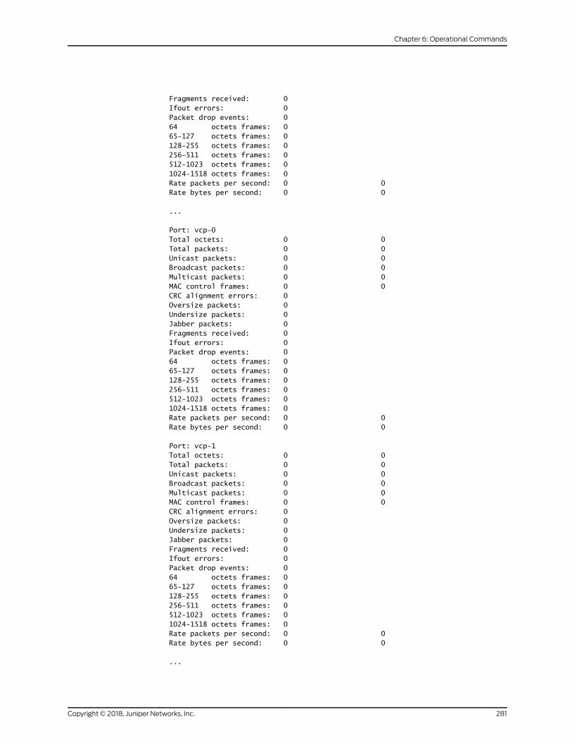
Fragments received: 0Ifout errors: 0Packet drop events: 064 octets frames: 065-127 octets frames: 0128-255 octets frames: 0256-511 octets frames: 0512-1023 octets frames: 01024-1518 octets frames: 0Rate packets per second: 0 0Rate bytes per second: 0 0
...
Port: vcp-0Total octets: 0 0Total packets: 0 0Unicast packets: 0 0Broadcast packets: 0 0Multicast packets: 0 0MAC control frames: 0 0CRC alignment errors: 0Oversize packets: 0Undersize packets: 0Jabber packets: 0Fragments received: 0Ifout errors: 0Packet drop events: 064 octets frames: 065-127 octets frames: 0128-255 octets frames: 0256-511 octets frames: 0512-1023 octets frames: 01024-1518 octets frames: 0Rate packets per second: 0 0Rate bytes per second: 0 0
Port: vcp-1Total octets: 0 0Total packets: 0 0Unicast packets: 0 0Broadcast packets: 0 0Multicast packets: 0 0MAC control frames: 0 0CRC alignment errors: 0Oversize packets: 0Undersize packets: 0Jabber packets: 0Fragments received: 0Ifout errors: 0Packet drop events: 064 octets frames: 065-127 octets frames: 0128-255 octets frames: 0256-511 octets frames: 0512-1023 octets frames: 01024-1518 octets frames: 0Rate packets per second: 0 0Rate bytes per second: 0 0
...
281Copyright © 2018, Juniper Networks, Inc.
Chapter 6: Operational Commands
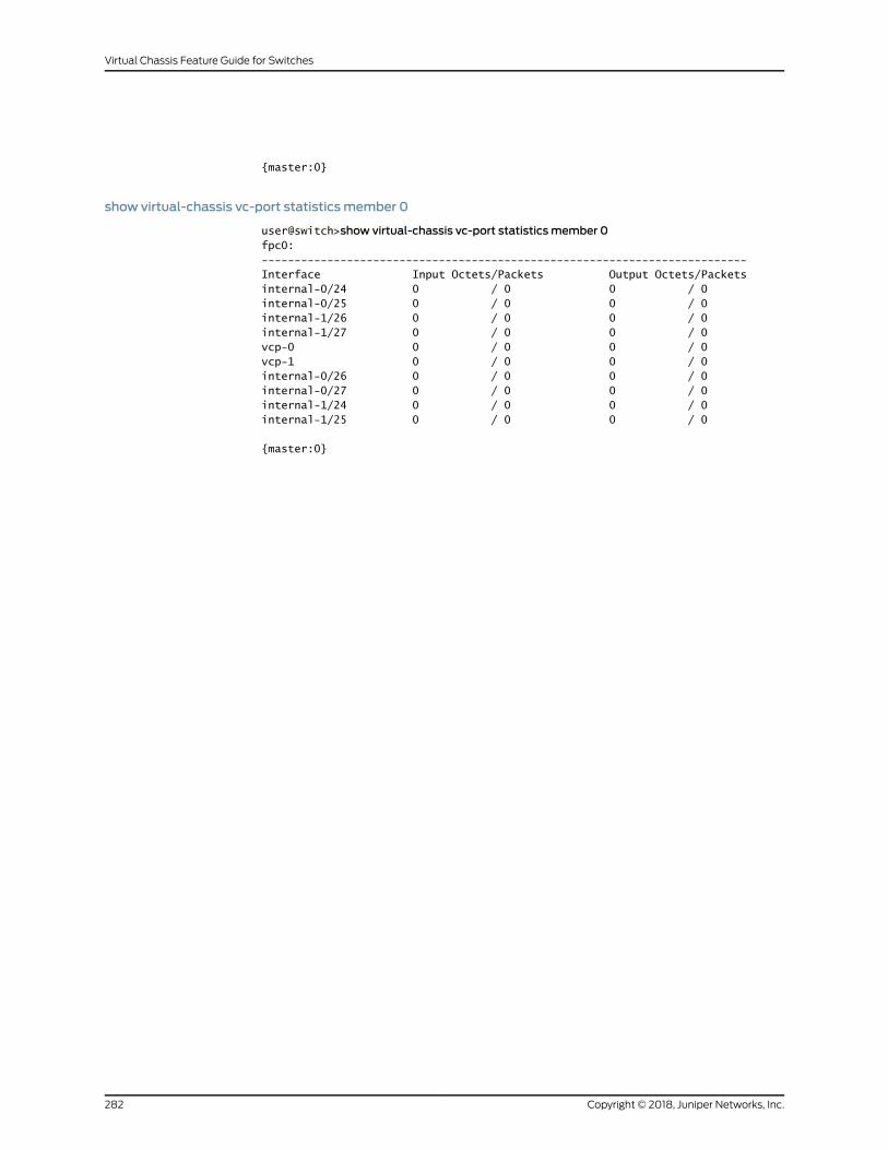
{master:0}
show virtual-chassis vc-port statisticsmember 0
user@switch>show virtual-chassis vc-port statisticsmember 0fpc0:--------------------------------------------------------------------------Interface Input Octets/Packets Output Octets/Packetsinternal-0/24 0 / 0 0 / 0internal-0/25 0 / 0 0 / 0internal-1/26 0 / 0 0 / 0internal-1/27 0 / 0 0 / 0vcp-0 0 / 0 0 / 0vcp-1 0 / 0 0 / 0internal-0/26 0 / 0 0 / 0internal-0/27 0 / 0 0 / 0internal-1/24 0 / 0 0 / 0internal-1/25 0 / 0 0 / 0
{master:0}
Copyright © 2018, Juniper Networks, Inc.282
Virtual Chassis Feature Guide for Switches