virtual prototyping for rapid product development
TRANSCRIPT
9
Virtual Prototyping for Rapid Product Development
S.H. Choi and H.H. Cheung Department of Industrial and Manufacturing Systems Engineering
The University of Hong Kong Hong Kong SAR
China
1. Introduction
Intensifying globalization and market competition has been driving the manufacturing industry to compete on continual reduction in lead-time and cost of product development while assuring high quality and wide varieties. Conventional manufacturing processes are, however, no longer sufficient to speed up product development to meet ever-increasing diversities of customer demands, stringent cost control, and complexity of new products. In recent years, various technologies have been developed to facilitate rapid product
development. Among these technologies, virtual prototyping (VP) and virtual
manufacturing (VM) may be regarded as important technological advancements. VP and
VM integrate virtual reality (VR) simulation techniques with design and manufacturing
processes to fabricate digital prototypes for subsequent stereoscopic visualisation, validation
and optimisation of product designs, as well as for evaluation of product assemblability and
producability.
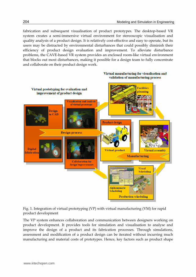
As shown in Figure 1, VP and VM together close a design-simulate-improve loop, in which design and production simulation techniques are integrated for visualisation and optimisation of a complete product development process in a VR environment to enhance product maturity. While VP focuses on the design process that digitally fabricates prototypes for evaluation and improvement of a product design, VM facilitates validation and optimisation of all subsequent stages of the downstream manufacturing process, such as facility layout, product assembly, and production scheduling. This design-simulate-improve loop can be iterated effectively and quickly to shorten the
product design and development cycle without incurring much additional costs. Indeed,
manufacturers can test all stages of product development in a virtual environment. As such,
they will be able to “get it right the first time” to enhance product maturity substantially at
an earlier stage, and to deliver quality products to market on time and within budget.
This chapter presents an integrated VP system for digital fabrication of complex prototypes
to facilitate rapid product development. The VP system comprises a suite of software
packages for multi-material layered manufacturing (MMLM) processes, including multi-
toolpath planning, build-time estimation and accuracy analysis, integrated with semi-
immersive desktop-based and full-immersive CAVE-based VR technology for digital
www.intechopen.com
Modeling and Simulation in Engineering
204
fabrication and subsequent visualisation of product prototypes. The desktop-based VR
system creates a semi-immersive virtual environment for stereoscopic visualisation and
quality analysis of a product design. It is relatively cost-effective and easy to operate, but its
users may be distracted by environmental disturbances that could possibly diminish their
efficiency of product design evaluation and improvement. To alleviate disturbance
problems, the CAVE-based VR system provides an enclosed room-like virtual environment
that blocks out most disturbances, making it possible for a design team to fully concentrate
and collaborate on their product design work.
Fig. 1. Integration of virtual prototyping (VP) with virtual manufacturing (VM) for rapid product development
The VP system enhances collaboration and communication between designers working on
product development. It provides tools for simulation and visualisation to analyse and
improve the design of a product and its fabrication processes. Through simulations,
assessment and modification of a product design can be iterated without incurring much
manufacturing and material costs of prototypes. Hence, key factors such as product shape
www.intechopen.com
Virtual Prototyping for Rapid Product Development
205
and manufacturability that may affect the product maturity and profitability can be
optimised quickly. Moreover, the resulting product design can be sent via the Internet to
customers for comments or marketing purposes. The VP system therefore facilitates rapid
product development and helps reduce time-to-market and cost considerably.
This chapter will first review the background and technologies related to development of
VP. The architecture and technical considerations of the proposed VP system will then be
discussed in detail. Case studies involving digital fabrication of complex, multi-material
objects will be presented to illustrate possible applications of the VP system for product
design and development.
2. Review of related works
2.1 Layered Manufacturing and multi-material layered manufacturing
Layered Manufacturing (LM), also called Rapid Prototyping (RP), is an additive
manufacturing process that produces a physical prototype from a 3D CAD model layer by
layer. The model can be generated from CAD designs or surface data captured from CT,
MRI and laser 3D scanning.
LM systems are widely adopted in manufacturing and medical applications to save cost and
time. Manufacturers use LM technology to produce prototypes of products for design
evaluation, and as master patterns for production tools.
Lopez and Wright (2002) studied the impact of LM on product design and development
processes. The study shows that LM may help shorten the product development cycle
drastically and enable designers to incorporate mechanical and ergonomic features into new
products easily. Tennyson et al. (2006) did a project to promote solid modelling and RP
technologies to Idaho’s rural manufactures in USA for rapid product development. The
result of the project illustrates that the manufacturers adopting such technologies can
enhance their capability to bring products to the marketplace more rapidly and with greater
success.
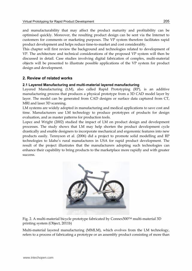
Fig. 2. A multi-material bicycle prototype fabricated by Connex500TM multi-material 3D printing system (Object, 2011b)
Multi-material layered manufacturing (MMLM), which evolves from the LM technology, refers to a process of fabricating a prototype or an assembly product consisting of more than
www.intechopen.com
Modeling and Simulation in Engineering
206
one component material from CAD models with material information, layer by layer. Due to the additive characteristics of LM processes, multiple materials can be selectively deposited on the related slice contours. Object (2011a) created a Connex500TM multi-material 3D printing system that jets multiple model materials simultaneously to fabricate multi-material parts or assemblies with different mechanical or physical properties, all in a single build. Figure 2 shows a printed multi-material bicycle prototype (Object, 2011b).
2.2 Virtual prototyping
VP is an innovative and powerful virtual simulation tool for facilitating rapid product development (Kerttula and Tokkonen, 2001; Mujber et al., 2004), and it has been successfully used in ship-building and car industries (Kim et al., 2002; Wöhlke and Schiller, 2005). It is a process of using virtual or digital prototypes and simulation techniques, often in a VR environment with innovative input and 3D stereoscopic output, to evaluate and improve a product design and to facilitate validation of its planning and manufacturing processes (Bochenek and Ragusa, 1998; Gomes and Zachmann, 1999; Kerttula and Tokkonen, 2001; Mujber et al., 2004; Patel et al., 2006; Weyrich and Drews, 1999). Through simulations, key factors such as the shape and the manufacturability of a product may be optimised without committing much to prototypes and tooling. Indeed, virtual simulation reduces the need for physical prototypes and hence minimizes tooling cost and material waste, and it allows manufacturers to “get it right the first time” and helps them deliver quality products to market on time and within budget. However, the current virtual simulation technique, which often adopts either semi- or full-immersive VR, is not without limitations, particularly with respect to the sense of immersion. Bochenek and Ragusa (1998) pointed out that it is important to appropriately select a VR system for facilitating product design and development processes. They investigated the use of four commercial VR display systems and found that the sense of immersion plays an important role in improving the design review practices, and that a higher sense of immersion will have better improvement. In general, semi-immersive VR systems (single-screen or desktop-based) are relatively easy to use, affordable, and of good resolution, though their users tend to be susceptible to environmental distractions. On the other hand, full-immersive VR systems (multi-screen or CAVE-based) can generate a relatively higher sense of immersion that facilitates user interaction and collaboration, but they are generally more expensive, of less resolution and poor portability, and needs special space requirements (Fairen et al. 2004; Hoffmann et al. 2006; Mujber et al. 2004). Hence, it is worthwhile to combine the good features of both semi- and full-immersive VR to enhance the versatility and effectiveness of virtual simulation at affordable cost. Therefore, it is desirable to develop a VP system for evaluation of product designs and digital fabrication of multi-material prototypes either in a semi-immersive environment or in a full-immersive, disturbance-free environment to facilitate rapid product development.
3. The proposed virtual prototyping system
The proposed VP system consists mainly of a suite of software packages to facilitate and simulate various stages of an MMLM process, including colour STL modelling, slicing,
www.intechopen.com
Virtual Prototyping for Rapid Product Development
207
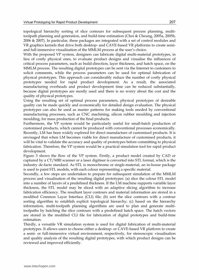
topological hierarchy sorting of slice contours for subsequent process planning, multi-toolpath planning and generation, and build-time estimation (Choi & Cheung, 2005a, 2005b, 2006 & 2007). In particular, these packages are integrated with a set of control modules and VR graphics kernels that drive both desktop- and CAVE-based VR platforms to create semi- and full-immersive visualisation of the MMLM process at the user’s choice. With the proposed VP system, designers can fabricate digital multi-material prototypes, in lieu of costly physical ones, to evaluate product designs and visualise the influences of critical process parameters, such as build-direction, layer thickness, and hatch space, on the MMLM process. The resulting digital prototypes can be sent via the Internet to customers to solicit comments, while the process parameters can be used for optimal fabrication of physical prototypes. This approach can considerably reduce the number of costly physical prototypes needed for rapid product development. As a result, the associated manufacturing overheads and product development time can be reduced substantially, because digital prototypes are mostly used and there is no worry about the cost and the quality of physical prototypes. Using the resulting set of optimal process parameters, physical prototypes of desirable quality can be made quickly and economically for detailed design evaluation. The physical prototypes can also be used as master patterns for making tools needed by conventional manufacturing processes, such as CNC machining, silicon rubber moulding and injection moulding, for mass production of the final products. Furthermore, the VP system would be particularly useful for small-batch production of customised products, which cannot be produced with conventional processes economically. Recently, LM has been widely explored for direct manufacture of customised products. It is envisaged that when LM becomes viable for direct manufacture of customised products, it will be vital to validate the accuracy and quality of prototypes before committing to physical fabrication. Therefore, the VP system would be a practical simulation tool for rapid product development. Figure 3 shows the flow of the VP system. Firstly, a product model created by CAD or captured by a CT/MRI scanner or a laser digitiser is converted into STL format, which is the industry de-facto standard. As STL is monochrome or single-material, an in-house package is used to paint STL models, with each colour representing a specific material. Secondly, a few steps are undertaken to prepare for subsequent simulation of the MMLM process and visualisation of the resulting digital prototypes: (a) slice the colour STL model into a number of layers of a predefined thickness. If the LM machine supports variable layer thickness, the STL model may be sliced with an adaptive slicing algorithm to increase fabrication efficiency. The resultant layer contours and material information are stored in a modified Common Layer Interface (CLI) file; (b) sort the slice contours with a contour sorting algorithm to establish explicit topological hierarchy; (c) based on the hierarchy information, multi-toolpath planning algorithms are used to plan and generate multi-toolpaths by hatching the slice contours with a predefined hatch space. The hatch vectors are stored in the modified CLI file for fabrication of digital prototypes and build-time estimation. Thirdly, a versatile VR simulation system is used for digital fabrication of multi-material prototypes. It allows users to choose either a desktop- or CAVE-based VR platform to create a semi- or full-immersive virtual environment, respectively, for stereoscopic visualisation and quality analysis of the resulting digital prototypes, with which product designs can be reviewed and improved efficiently.
www.intechopen.com
Modeling and Simulation in Engineering
208
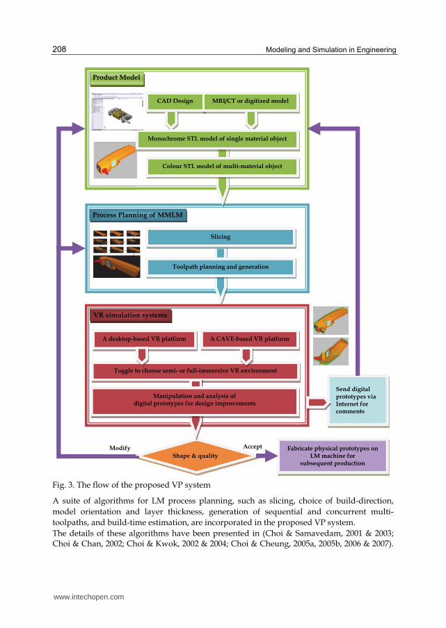
Fig. 3. The flow of the proposed VP system
A suite of algorithms for LM process planning, such as slicing, choice of build-direction,
model orientation and layer thickness, generation of sequential and concurrent multi-
toolpaths, and build-time estimation, are incorporated in the proposed VP system.
The details of these algorithms have been presented in (Choi & Samavedam, 2001 & 2003; Choi & Chan, 2002; Choi & Kwok, 2002 & 2004; Choi & Cheung, 2005a, 2005b, 2006 & 2007).
www.intechopen.com
Virtual Prototyping for Rapid Product Development
209
This chapter focuses on the development of the VR system. In particular, it addresses the enhancement of versatility and effectiveness of virtual simulation for product design and digital fabrication of multi-material prototypes at affordable cost. The following section describes the desktop- and the CAVE-based VR platforms in detail.
3.1 The desktop-based VR system
The desktop-based VR system consists mainly of a suite of software packages for
stereoscopic visualisation of product designs and optimisation of MMLM processes. The
software interfaces with commercial desktop-based VR hardware to display a model for
stereoscopic visualisation. Using a desktop monitor, which is relatively small but highly
portable, a user wears a pair of active shutter glasses that generate stereoscopic feelings by
synchronising with the display device to switch on and off the images to the left eye and the
right eye alternatively.
This creates a semi-immersive VR environment in which a designer can stereoscopically
visualise product designs and perform quality analysis. If a much larger display is needed, a
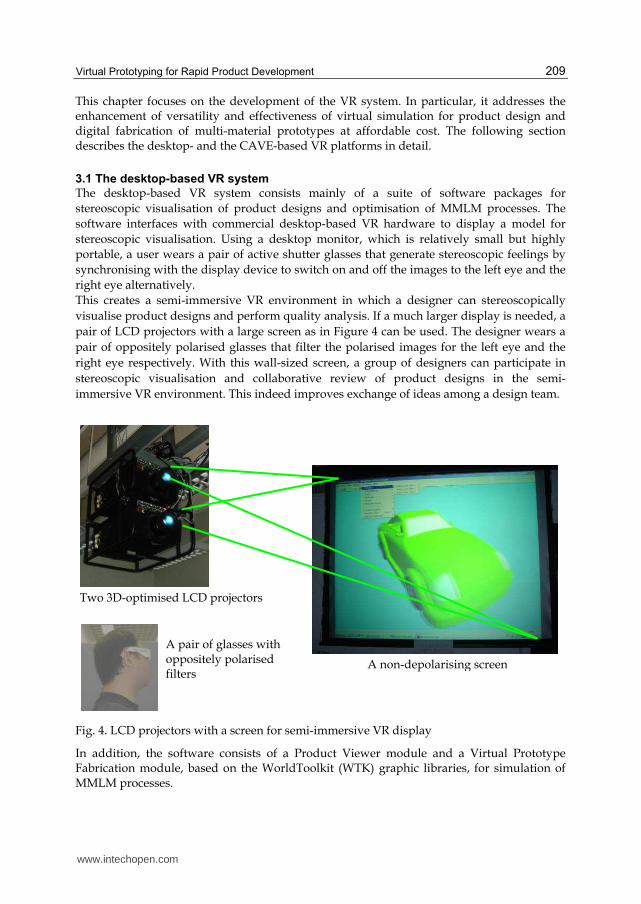
pair of LCD projectors with a large screen as in Figure 4 can be used. The designer wears a
pair of oppositely polarised glasses that filter the polarised images for the left eye and the
right eye respectively. With this wall-sized screen, a group of designers can participate in
stereoscopic visualisation and collaborative review of product designs in the semi-
immersive VR environment. This indeed improves exchange of ideas among a design team.
Fig. 4. LCD projectors with a screen for semi-immersive VR display
In addition, the software consists of a Product Viewer module and a Virtual Prototype Fabrication module, based on the WorldToolkit (WTK) graphic libraries, for simulation of MMLM processes.
A non-depolarising screen
Two 3D-optimised LCD projectors
A pair of glasses with oppositely polarised filters
www.intechopen.com
Modeling and Simulation in Engineering
210
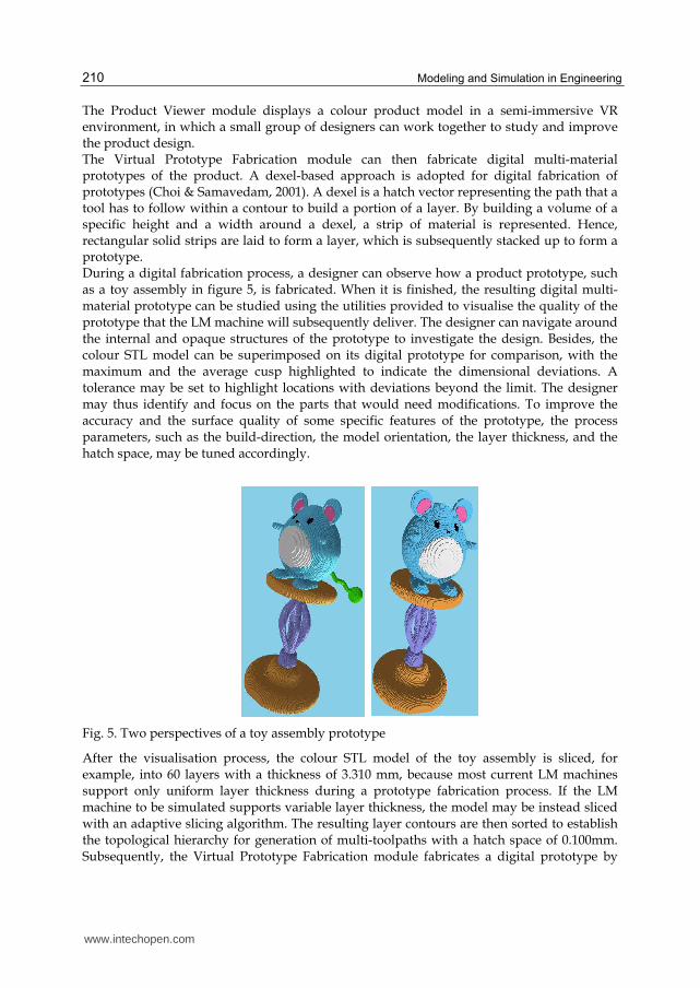
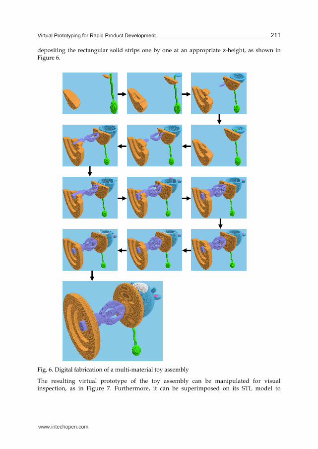
The Product Viewer module displays a colour product model in a semi-immersive VR environment, in which a small group of designers can work together to study and improve the product design. The Virtual Prototype Fabrication module can then fabricate digital multi-material prototypes of the product. A dexel-based approach is adopted for digital fabrication of prototypes (Choi & Samavedam, 2001). A dexel is a hatch vector representing the path that a tool has to follow within a contour to build a portion of a layer. By building a volume of a specific height and a width around a dexel, a strip of material is represented. Hence, rectangular solid strips are laid to form a layer, which is subsequently stacked up to form a prototype. During a digital fabrication process, a designer can observe how a product prototype, such as a toy assembly in figure 5, is fabricated. When it is finished, the resulting digital multi-material prototype can be studied using the utilities provided to visualise the quality of the prototype that the LM machine will subsequently deliver. The designer can navigate around the internal and opaque structures of the prototype to investigate the design. Besides, the colour STL model can be superimposed on its digital prototype for comparison, with the maximum and the average cusp highlighted to indicate the dimensional deviations. A tolerance may be set to highlight locations with deviations beyond the limit. The designer may thus identify and focus on the parts that would need modifications. To improve the accuracy and the surface quality of some specific features of the prototype, the process parameters, such as the build-direction, the model orientation, the layer thickness, and the hatch space, may be tuned accordingly.
Fig. 5. Two perspectives of a toy assembly prototype
After the visualisation process, the colour STL model of the toy assembly is sliced, for example, into 60 layers with a thickness of 3.310 mm, because most current LM machines support only uniform layer thickness during a prototype fabrication process. If the LM machine to be simulated supports variable layer thickness, the model may be instead sliced with an adaptive slicing algorithm. The resulting layer contours are then sorted to establish the topological hierarchy for generation of multi-toolpaths with a hatch space of 0.100mm. Subsequently, the Virtual Prototype Fabrication module fabricates a digital prototype by
www.intechopen.com
Virtual Prototyping for Rapid Product Development
211
depositing the rectangular solid strips one by one at an appropriate z-height, as shown in Figure 6.
Fig. 6. Digital fabrication of a multi-material toy assembly
The resulting virtual prototype of the toy assembly can be manipulated for visual inspection, as in Figure 7. Furthermore, it can be superimposed on its STL model to
www.intechopen.com
Modeling and Simulation in Engineering
212
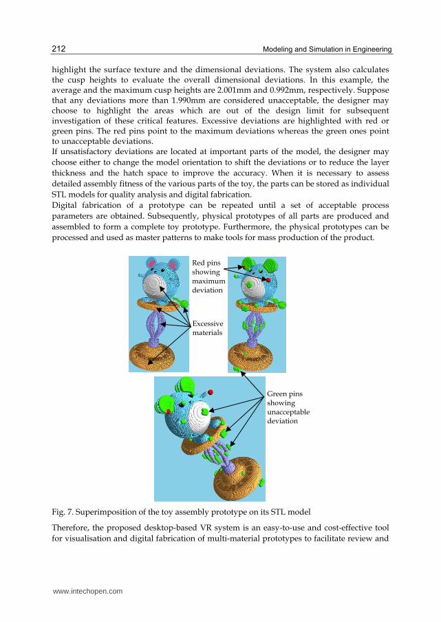
highlight the surface texture and the dimensional deviations. The system also calculates the cusp heights to evaluate the overall dimensional deviations. In this example, the average and the maximum cusp heights are 2.001mm and 0.992mm, respectively. Suppose that any deviations more than 1.990mm are considered unacceptable, the designer may choose to highlight the areas which are out of the design limit for subsequent investigation of these critical features. Excessive deviations are highlighted with red or green pins. The red pins point to the maximum deviations whereas the green ones point to unacceptable deviations. If unsatisfactory deviations are located at important parts of the model, the designer may
choose either to change the model orientation to shift the deviations or to reduce the layer
thickness and the hatch space to improve the accuracy. When it is necessary to assess
detailed assembly fitness of the various parts of the toy, the parts can be stored as individual
STL models for quality analysis and digital fabrication.
Digital fabrication of a prototype can be repeated until a set of acceptable process
parameters are obtained. Subsequently, physical prototypes of all parts are produced and
assembled to form a complete toy prototype. Furthermore, the physical prototypes can be
processed and used as master patterns to make tools for mass production of the product.
Fig. 7. Superimposition of the toy assembly prototype on its STL model
Therefore, the proposed desktop-based VR system is an easy-to-use and cost-effective tool
for visualisation and digital fabrication of multi-material prototypes to facilitate review and
Excessive materials
Red pins showing maximum deviation
Green pins showing unacceptable deviation
www.intechopen.com
Virtual Prototyping for Rapid Product Development
213
improvement of product designs. However, the semi-immersive VR environment may be
susceptible to environmental disturbances, diminishing the designers’ true feeling and
concentration and hence their efficiency in the design process.
To address this problem, the level of immersion is enhanced by integrating the VP system
with a CAVE-based VR system with multiple screens to provide a full-immersive virtual
environment for vivid stereoscopic visualisation and interaction in a natural way. As such, a
design team can fully immerse in exploration, study, and improvement of a product design,
including assemblies, sub-assemblies, and components, well before they ever exist
physically in reality. Hence, the time and cost of product development can be further
reduced.
3.2 The CAVE-based VR platform
The CAVE-based VR platform consists of a cluster of PCs with a cubicle of three walls on a
floor. An immersive virtual environment is created by projecting stereoscopic images on
three 10ft x 8ft screens on the walls, namely the front, the right, and the left, respectively,
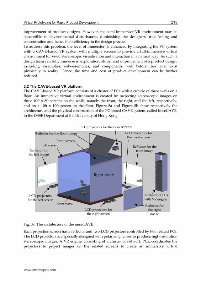
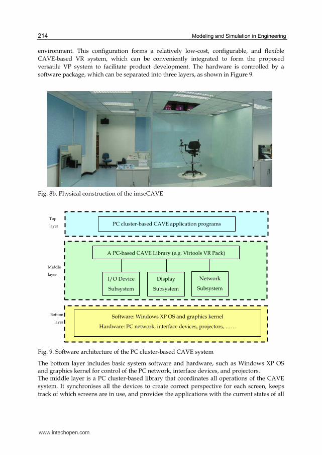
and on a 10ft x 10ft screen on the floor. Figure 8a and Figure 8b show respectively the
architecture and the physical construction of the PC-based CAVE system, called imseCAVE,
in the IMSE Department at the University of Hong Kong.
Fig. 8a. The architecture of the imseCAVE
Each projection screen has a reflector and two LCD projectors controlled by two related PCs.
The LCD projectors are specially designed with polarising lenses to produce high-resolution
stereoscopic images. A VR engine, consisting of a cluster of network PCs, coordinates the
projectors to project images on the related screens to create an immersive virtual
Reflector for the floor image
LCD projectors for the floor screen
Front screen
Left screen
Reflector for the left image
Right screen
LCD projectors for the left screen
Floor screen
LCD projectors for the right screen
Reflector for the right
image
LCD projectors for the front screen
Reflector for the front image
A cluster of PCs with VR engine
www.intechopen.com
Modeling and Simulation in Engineering
214
environment. This configuration forms a relatively low-cost, configurable, and flexible
CAVE-based VR system, which can be conveniently integrated to form the proposed
versatile VP system to facilitate product development. The hardware is controlled by a
software package, which can be separated into three layers, as shown in Figure 9.
Fig. 8b. Physical construction of the imseCAVE
Fig. 9. Software architecture of the PC cluster-based CAVE system
The bottom layer includes basic system software and hardware, such as Windows XP OS and graphics kernel for control of the PC network, interface devices, and projectors. The middle layer is a PC cluster-based library that coordinates all operations of the CAVE
system. It synchronises all the devices to create correct perspective for each screen, keeps
track of which screens are in use, and provides the applications with the current states of all
PC cluster-based CAVE application programs Top
layer
A PC-based CAVE Library (e.g. Virtools VR Pack)
I/O Device
Subsystem
Display
Subsystem
Network
Subsystem
Middle
layer
Software: Windows XP OS and graphics kernel
Hardware: PC network, interface devices, projectors, ……
Bottom
layer
www.intechopen.com
Virtual Prototyping for Rapid Product Development
215
the CAVE elements. It consists of three sub-systems: (i) I/O device sub-system for
controlling I/O devices; (ii) display subsystem for projecting images on the corresponding
screens; and (iii) the network subsystem for keeping communication and synchronisation
between all clustering PCs.
The top layer is a package of tailor-made application programs, developed with the PC
cluster-based CAVE library, for immersive visualisation and simulation in the CAVE
system. This application package is implemented in an object-oriented programming tool,
called the Virtools Dev, and its add-on library, called Virtools VR Pack (Virtools, 2006). The
Virtools Dev contains a suite of algorithms to help programmers create, visualise,
manipulate, and track objects in the virtual environment. Besides, the Virtools VR Pack
allows users to tailor applications for producing full-immersive, life experiences using the
PC-based distributed computing.
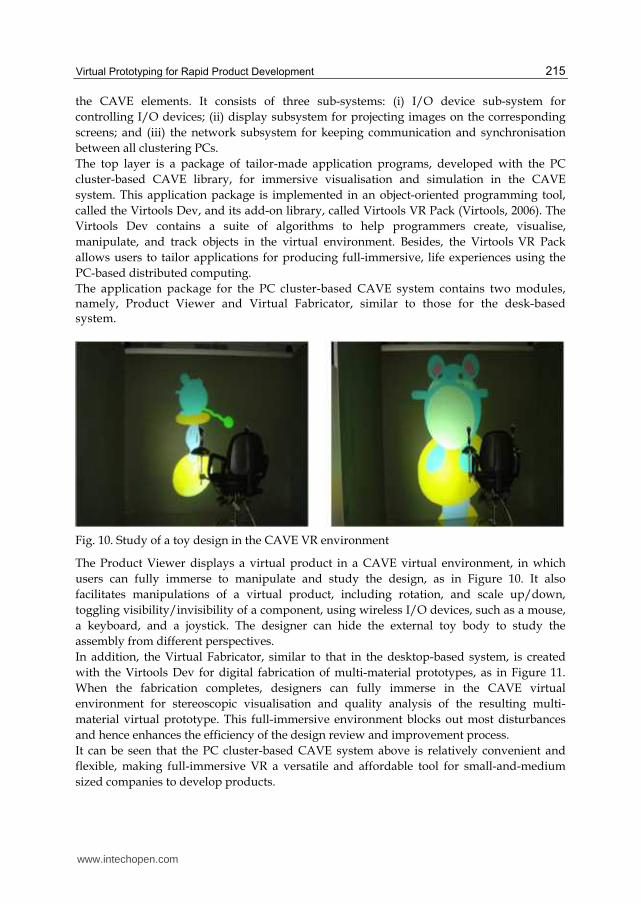
The application package for the PC cluster-based CAVE system contains two modules, namely, Product Viewer and Virtual Fabricator, similar to those for the desk-based system.
Fig. 10. Study of a toy design in the CAVE VR environment
The Product Viewer displays a virtual product in a CAVE virtual environment, in which
users can fully immerse to manipulate and study the design, as in Figure 10. It also
facilitates manipulations of a virtual product, including rotation, and scale up/down,
toggling visibility/invisibility of a component, using wireless I/O devices, such as a mouse,
a keyboard, and a joystick. The designer can hide the external toy body to study the
assembly from different perspectives.
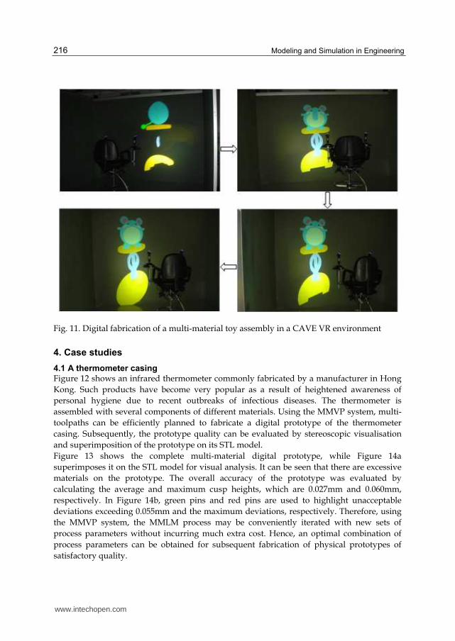
In addition, the Virtual Fabricator, similar to that in the desktop-based system, is created
with the Virtools Dev for digital fabrication of multi-material prototypes, as in Figure 11.
When the fabrication completes, designers can fully immerse in the CAVE virtual
environment for stereoscopic visualisation and quality analysis of the resulting multi-
material virtual prototype. This full-immersive environment blocks out most disturbances
and hence enhances the efficiency of the design review and improvement process.
It can be seen that the PC cluster-based CAVE system above is relatively convenient and
flexible, making full-immersive VR a versatile and affordable tool for small-and-medium
sized companies to develop products.
www.intechopen.com
Modeling and Simulation in Engineering
216
Fig. 11. Digital fabrication of a multi-material toy assembly in a CAVE VR environment
4. Case studies
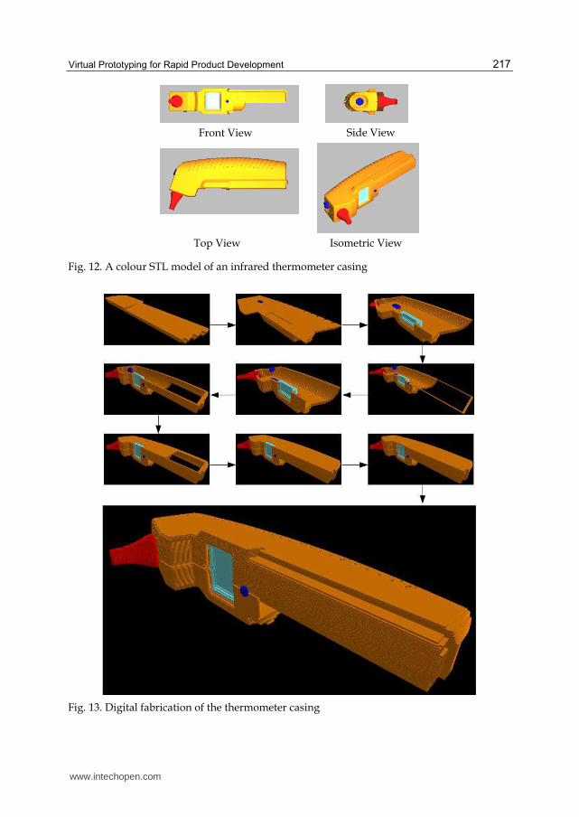
4.1 A thermometer casing
Figure 12 shows an infrared thermometer commonly fabricated by a manufacturer in Hong
Kong. Such products have become very popular as a result of heightened awareness of
personal hygiene due to recent outbreaks of infectious diseases. The thermometer is
assembled with several components of different materials. Using the MMVP system, multi-
toolpaths can be efficiently planned to fabricate a digital prototype of the thermometer
casing. Subsequently, the prototype quality can be evaluated by stereoscopic visualisation
and superimposition of the prototype on its STL model.
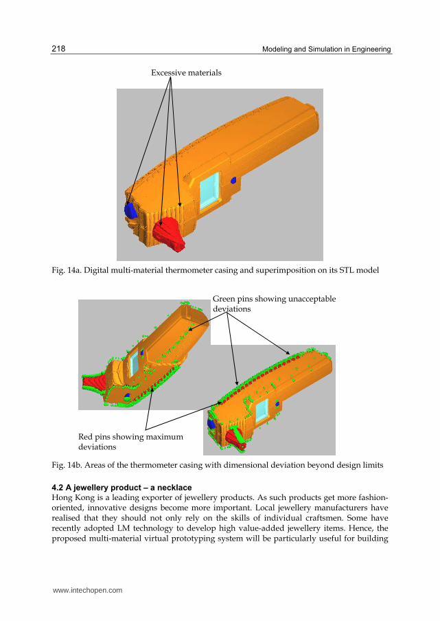
Figure 13 shows the complete multi-material digital prototype, while Figure 14a
superimposes it on the STL model for visual analysis. It can be seen that there are excessive
materials on the prototype. The overall accuracy of the prototype was evaluated by
calculating the average and maximum cusp heights, which are 0.027mm and 0.060mm,
respectively. In Figure 14b, green pins and red pins are used to highlight unacceptable
deviations exceeding 0.055mm and the maximum deviations, respectively. Therefore, using
the MMVP system, the MMLM process may be conveniently iterated with new sets of
process parameters without incurring much extra cost. Hence, an optimal combination of
process parameters can be obtained for subsequent fabrication of physical prototypes of
satisfactory quality.
www.intechopen.com
Virtual Prototyping for Rapid Product Development
217
Fig. 12. A colour STL model of an infrared thermometer casing
Fig. 13. Digital fabrication of the thermometer casing
Front View Side View
Top View Isometric View
www.intechopen.com
Modeling and Simulation in Engineering
218
Fig. 14a. Digital multi-material thermometer casing and superimposition on its STL model
Fig. 14b. Areas of the thermometer casing with dimensional deviation beyond design limits
4.2 A jewellery product – a necklace
Hong Kong is a leading exporter of jewellery products. As such products get more fashion-oriented, innovative designs become more important. Local jewellery manufacturers have realised that they should not only rely on the skills of individual craftsmen. Some have recently adopted LM technology to develop high value-added jewellery items. Hence, the proposed multi-material virtual prototyping system will be particularly useful for building
Excessive materials
Green pins showing unacceptable deviations
Red pins showing maximum deviations
www.intechopen.com
Virtual Prototyping for Rapid Product Development
219
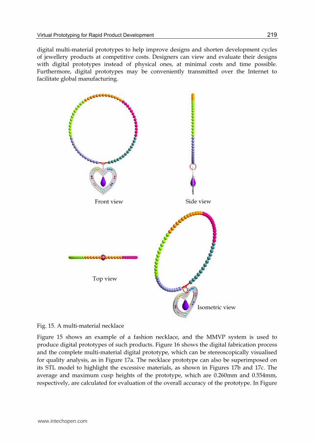
digital multi-material prototypes to help improve designs and shorten development cycles of jewellery products at competitive costs. Designers can view and evaluate their designs with digital prototypes instead of physical ones, at minimal costs and time possible. Furthermore, digital prototypes may be conveniently transmitted over the Internet to facilitate global manufacturing.
Fig. 15. A multi-material necklace
Figure 15 shows an example of a fashion necklace, and the MMVP system is used to
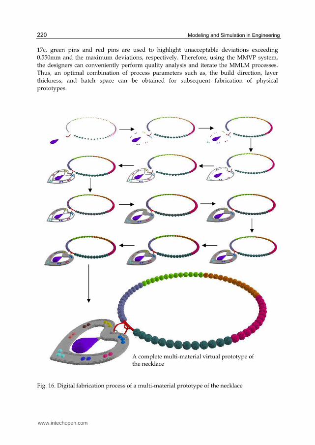
produce digital prototypes of such products. Figure 16 shows the digital fabrication process
and the complete multi-material digital prototype, which can be stereoscopically visualised
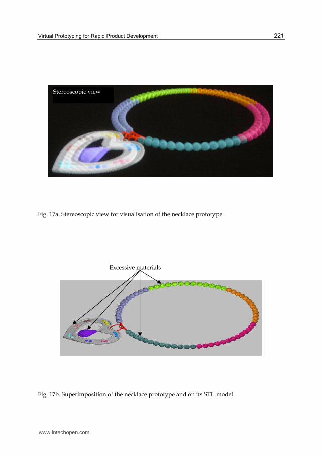
for quality analysis, as in Figure 17a. The necklace prototype can also be superimposed on
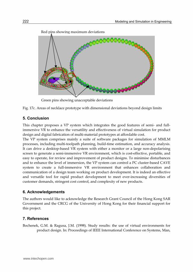
its STL model to highlight the excessive materials, as shown in Figures 17b and 17c. The
average and maximum cusp heights of the prototype, which are 0.260mm and 0.554mm,
respectively, are calculated for evaluation of the overall accuracy of the prototype. In Figure
Front view Side view
Top view
Isometric view
www.intechopen.com
Modeling and Simulation in Engineering
220
17c, green pins and red pins are used to highlight unacceptable deviations exceeding
0.550mm and the maximum deviations, respectively. Therefore, using the MMVP system,
the designers can conveniently perform quality analysis and iterate the MMLM processes.
Thus, an optimal combination of process parameters such as, the build direction, layer
thickness, and hatch space can be obtained for subsequent fabrication of physical
prototypes.
Fig. 16. Digital fabrication process of a multi-material prototype of the necklace
A complete multi-material virtual prototype of the necklace
www.intechopen.com
Virtual Prototyping for Rapid Product Development
221
Fig. 17a. Stereoscopic view for visualisation of the necklace prototype
Fig. 17b. Superimposition of the necklace prototype and on its STL model
Stereoscopic view
Excessive materials
www.intechopen.com
Modeling and Simulation in Engineering
222
Fig. 17c. Areas of necklace prototype with dimensional deviations beyond design limits
5. Conclusion
This chapter proposes a VP system which integrates the good features of semi- and full-
immersive VR to enhance the versatility and effectiveness of virtual simulation for product
design and digital fabrication of multi-material prototypes at affordable cost.
The VP system comprises mainly a suite of software packages for simulation of MMLM
processes, including multi-toolpath planning, build-time estimation, and accuracy analysis.
It can drive a desktop-based VR system with either a monitor or a large non-depolarising
screen to generate a semi-immersive VR environment, which is cost-effective, portable, and
easy to operate, for review and improvement of product designs. To minimise disturbances
and to enhance the level of immersion, the VP system can control a PC cluster-based CAVE
system to create a full-immersive VR environment that enhances collaboration and
communication of a design team working on product development. It is indeed an effective
and versatile tool for rapid product development to meet ever-increasing diversities of
customer demands, stringent cost control, and complexity of new products.
6. Acknowledgements
The authors would like to acknowledge the Research Grant Council of the Hong Kong SAR
Government and the CRCG of the University of Hong Kong for their financial support for
this project.
7. References
Bochenek, G.M. & Ragusa, J.M. (1998). Study results: the use of virtual environments for
product design. In: Proceedings of IEEE International Conference on Systems, Man,
Red pins showing maximum deviations
Green pins showing unacceptable deviations
www.intechopen.com
Virtual Prototyping for Rapid Product Development
223
and Cybernetics, Hyatt Regency La Jolla, San Diego, California, USA, 11-14
October, 1998. p. 250-1253.
Choi, S.H. & Chan, A.M.M. (2002). A dexel-based virtual prototyping system for product
development. Rapid Prototyping Journal, Vol.8, No.5, 300-314.
Choi, S.H. & Cheung, H.H. (2005a). A multi-material virtual prototyping system. Computer-
Aided Design, Vol.37, No.1, 123-136.
Choi, S.H. & Cheung, H.H. (2005b). A multi-material virtual prototyping system for product
development and biomedical engineering. Computer-Aided Design and Applications,
Vol.2, No.1-4, 329-338.
Choi, S.H. & Cheung, H.H. (2006). A topological hierarchy-based approach to toolpath
planning for multi-material layered manufacturing. Computer-Aided Design, Vol.38,
No.2, 143-156.
Choi, S.H. & Cheung, H.H. (2007). Multi-material virtual prototyping for product
development and biomedical. Computers In Industry, Vol.58, No.5, 438-452.
Choi, S.H. & Kwok, K.T. (2002). A tolerant slicing algorithm for layered manufacturing.
Rapid Prototyping Journal, Vol.8, No.3, 161-179.
Choi, S.H. & Kwok, K.T. (2004). A topological hierarchy-sorting algorithm for layered
manufacturing. Rapid Prototyping Journal, Vol.10, No.2, 98-113.
Choi, S.H. & Samavedam, S. (2001). Visualisation of rapid prototyping. Rapid Prototyping
Journal, Vol.7, No.2, 99–114.
Choi, S.H. & Samavedam, S. (2003). Modelling and optimisation of rapid prototyping.
Computers in Industry, Vol.47, No.1, 39-53.
Gomes de Sá, A. & Zachmann, G. (1999). Virtual reality as a tool for verification of assembly
and maintenance processes. Computers & Graphics, Vol.23, No.3, 389-403.
Kerttula, M. & Tokkonen, T. (2001). Virtual design of multiengineering electronics systems.
IEEE Computer, Vol.34, No.11, 71-79.
Kim, H.T., Lee, J.K., Park, J.H., Park, B.J. & Jang, D.S. (2002). Applying digital manufacturing
technology to ship production and the maritime environment. Integrated
Manufacturing Systems, 13(5):295-305.
Lopez, S.M. & Wright, P.K. (2002). The role of rapid prototyping in the product
development process: a case study on the ergonomic factors of handheld video
games. Rapid Prototyping Journal, Vol.8, No.2, 116-125.
Mujber, T.S., Szecsi, T. & Hashmi, M.S.J. (2004). Virtual reality applications in
manufacturing process simulation. Journal of Materials Processing Technology, 155-
156:1834-1838.
Object, (2011a). http://www.objet.com/3D-Printer/Objet_connex500/.
Object, (2011b). http://www.objetblog.com/2011/05/23/objet-to-demonstrate-unique-
multi-material-3d-printing-applications-at-rapid/.
Patel, H., Sharples, S., Letourneur, S., Johansson, E., Hoffmann, H., Lorisson, L., Saluaar, D.
& Stefani, O. (2006). Practical evaluations of real user company needs for
visualization technologies. International Journal of Human-Computer Studies, Vol. 64,
No.3, 267-279.
www.intechopen.com
Modeling and Simulation in Engineering
224
Tennyson, S., McCain, G., Hatten, S. & Eggert, R. (2006). Case study: promoting design
automation by rural manufacturers. Rapid Prototyping Journal, Vol.12, No.5, 304-
309.
Virtools, (2006). http://www.virtools.com.
Weyrich, M. & Drews, P. (1999). An interactive environment for virtual manufacturing: the
virtual workbench. Computers in Industry, Vol.38, No.1, 5-15.
Wöhlke, G. & Schiller, E. (2005). Digital planning validation in automotive industry.
Computers in Industry, Vol.56, No.4, 393-405.
www.intechopen.com
Modeling and Simulation in EngineeringEdited by Prof. Catalin Alexandru
ISBN 978-953-51-0012-6Hard cover, 298 pagesPublisher InTechPublished online 07, March, 2012Published in print edition March, 2012
InTech EuropeUniversity Campus STeP Ri Slavka Krautzeka 83/A 51000 Rijeka, Croatia Phone: +385 (51) 770 447 Fax: +385 (51) 686 166www.intechopen.com
InTech ChinaUnit 405, Office Block, Hotel Equatorial Shanghai No.65, Yan An Road (West), Shanghai, 200040, China
Phone: +86-21-62489820 Fax: +86-21-62489821
This book provides an open platform to establish and share knowledge developed by scholars, scientists, andengineers from all over the world, about various applications of the modeling and simulation in the designprocess of products, in various engineering fields. The book consists of 12 chapters arranged in two sections(3D Modeling and Virtual Prototyping), reflecting the multidimensionality of applications related to modelingand simulation. Some of the most recent modeling and simulation techniques, as well as some of the mostaccurate and sophisticated software in treating complex systems, are applied. All the original contributions inthis book are jointed by the basic principle of a successful modeling and simulation process: as complex asnecessary, and as simple as possible. The idea is to manipulate the simplifying assumptions in a way thatreduces the complexity of the model (in order to make a real-time simulation), but without altering the precisionof the results.
How to referenceIn order to correctly reference this scholarly work, feel free to copy and paste the following:
S.H. Choi and H.H. Cheung (2012). Virtual Prototyping for Rapid Product Development, Modeling andSimulation in Engineering, Prof. Catalin Alexandru (Ed.), ISBN: 978-953-51-0012-6, InTech, Available from:http://www.intechopen.com/books/modeling-and-simulation-in-engineering/virtual-prototyping-for-rapid-product-development

© 2012 The Author(s). Licensee IntechOpen. This is an open access articledistributed under the terms of the Creative Commons Attribution 3.0License, which permits unrestricted use, distribution, and reproduction inany medium, provided the original work is properly cited.