virtual synchronous machine control of vsc hvdc for power
TRANSCRIPT
Virtual Synchronous Machine Control of VSCHVDC for Power System Oscillation Damping
Javier Roldan-Perez∗, Jon Are Suul†, Salvatore D’Arco†, Alberto Rodrıguez-Cabero∗, and Milan Prodanovic∗∗IMDEA Energy Institute, Madrid, Spain. †SINTEF Energy Research, Trondheim, Norway.
[email protected], {jon.a.suul, salvatore.darco}@sintef.no, {alberto.rodriguez, milan.prodanovic}@imdea.org
Abstract—Two different methods for implementing inertialdamping on a Virtual Synchronous Machine (VSM) and theirpotential for attenuating power system oscillations when utilizedin a VSC HVDC terminal are investigated in this paper. As areference case, the VSM is considered with only a frequencydroop providing damping in the virtual swing equation. Then,the effect of damping based on high-pass filtering of the virtualspeed is compared to damping based on high-pass filtering of themeasured grid frequency. A simplified model of a power systemwith two equivalent generators and a VSC HVDC terminalis introduced as a case study. Analysis of the small-signaldynamics indicates that damping based on the VSM speed haslimited influence on the power system oscillations, while improvedattenuation can be obtained by introducing damping based onthe locally measured grid frequency. The presented analysis andthe operation of the proposed VSM-based damping strategy isvalidated by numerical simulation of a 150 MVA VSM controlledVSC HVDC terminal connected to a dynamic model of theassumed grid configuration.
Index Terms—Power System Oscillation Damping, VirtualInertia, Virtual Synchronous Machine, VSC-HVDC.
I. INTRODUCTION
HVDC transmission systems have for long time beenutilised to damp oscillations in power systems by introducingadditional damping controllers. The first examples of suchauxiliary control functions for damping low frequency os-cillations were implemented with traditional thyristor-basedHVDC terminals [1–3]. However, modern Voltage SourceConverter (VSC) technology provides faster control responseand decoupled control of active and reactive power. Thus, VSCHVDC terminals can provide power oscillation damping aswell as additional ancillary services, and can allow for fastprimary frequency control influencing the equivalent inertialresponse of the ac power system [4–6]. The fast response canalso enable VSC HVDC converter stations to provide virtualinertia support to the power system by emulating the inertialresponse of synchronous machines [7–9].
With increasing share of converter interfaced generation andcorresponding decommissioning of traditional power plants,
The work of IMDEA Energy Institute in this paper received financialsupport from the Community of Madrid Government, Spain, through theresearch project PRICAM (S2013/ICE-2933), and from the mobility programJose Castillejo (CAS17/00386) funded by the Spanish Government. The workof SINTEF Energy Research was supported by the project HVDC InertiaProvision (HVDC Pro), financed by the ENERGIX program of the ResearchCouncil of Norway (project number 268053/E20) and the industry partners;Statnett, Equinor, RTE and ELIA.
the potential for providing virtual inertia from HVDC con-verter stations is expected to become increasingly important.Such virtual inertia control can generally be implementedby two approaches [10]: i) Frequency-derivative-based Iner-tia Emulation (df/dt-IE), where the power response that asynchronous machine would provide is calculated from themeasured grid frequency and added to the power referenceof a conventional control system. ii) Virtual Synchronous Ma-chines (VSMs), where the control system relies on an internalsimulation of a virtual swing equation with its correspondingpower-balance-based grid synchronization mechanism. Uti-lization of df/dt-IE control allows for inertia emulation asan added feature of a conventional control system based ongrid synchronisation and frequency measurement by a PhaseLocked Loop (PLL), but relies on a relatively strong grid.However, VSMs can operate in islanded conditions and inertia-less power systems, as well as under strong grid conditions.
Because of the operational flexibility offered by VSM-basedcontrol strategies, a wide range of implementations and appli-cations have been proposed [8, 10–14]. Furthermore, auxiliaryfunctions for supporting the power system operation can beintegrated in the VSM control framework as discussed in [15–18]. Several recent studies have also analysed how VSM-basedcontrol schemes can be utilised to damp local oscillationsin small-scale power systems [15, 16, 19, 20]. However, lessattention has been directed towards the application of VSM-based control for damping of low frequency oscillations.Thus, only a few publications have addressed how VSMs canbe utilized to influence oscillations originating from existingsynchronous machines in a large-scale power system [21, 22].
In this paper, the utilisation of a VSM for damping ofpower system oscillations based only on local measurementsis investigated. For this purpose, a simplified model of a powersystem with two equivalent generators is introduced. This
Lc Lo
Cfu1
ci
u1
Governorcontroller
Voltage
controller
Voltage
excitation
u2
Generatorcontroller
VSM
controller
Transmission
line2
Equivalent model of a generatorG1
G2
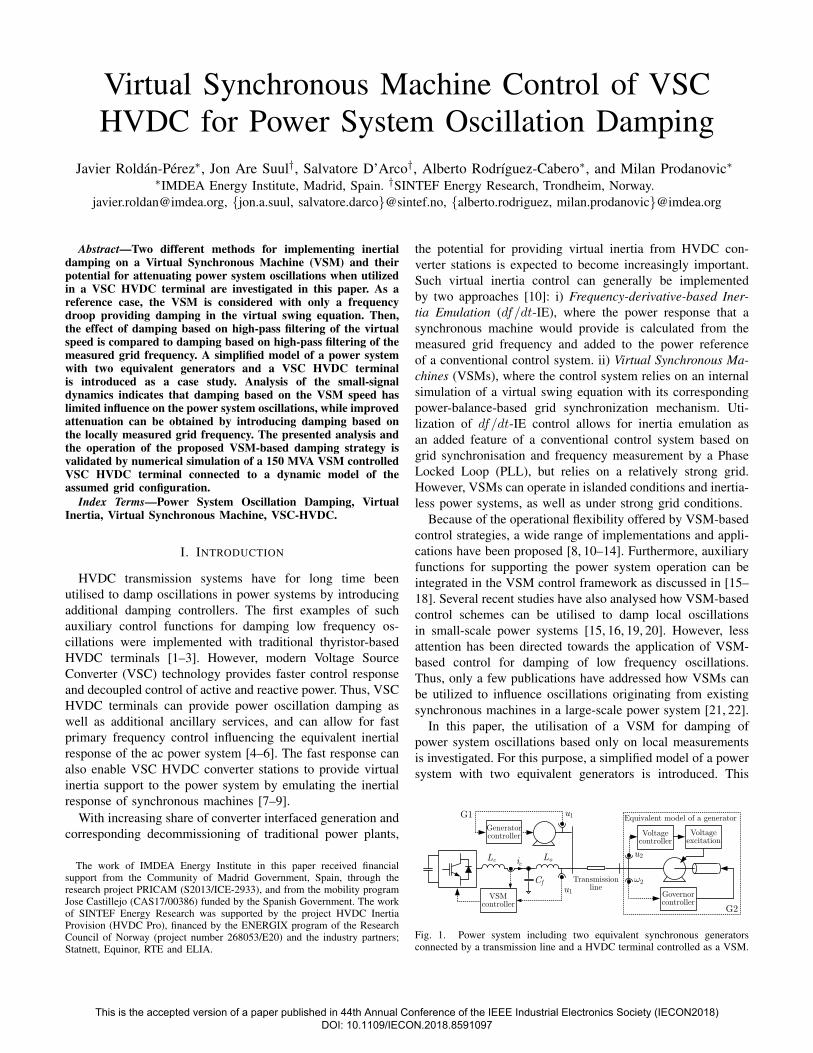
Fig. 1. Power system including two equivalent synchronous generatorsconnected by a transmission line and a HVDC terminal controlled as a VSM.
This is the accepted version of a paper published in 44th Annual Conference of the IEEE Industrial Electronics Society (IECON2018) DOI: 10.1109/IECON.2018.8591097

+
Vdc
Lcug
Lo
abc
dq
Cf ugCQ(s )
ug
ugug*Q*
Pm+
++
_
+DQ
K
1J
1s
abs(·)
θ
eqed= e0
s
Vs
| || |
_
*+
Lgci
→
→→ →
s
s'
_
+
c*
Current controller
ı→
ı→
Voltage-controlled VSM
abc
dqs
i
Equivalent gridmodel
Voltage
controller
u
_
+
abc
dq
f
+
Pd
s
uf→
_
(1) The grid model includes the power system dynamics(2) The additional power is used to damp oscillations
(1)
(2)
c
c
_
Pe
Qo
Fig. 2. Electrical and control system overview for the VSM connected to the power system.
model allows for small-signal analysis of how the control of aVSM will influence the oscillations in the power system. Then,two different implementations of the internal damping of theVSM are presented and a parametric analysis of the simplifiedsystem model is conducted to study the impact on the powersystem oscillations. By this analysis, it is demonstrated thatimplementation of the VSM damping based only on the localvirtual speed has limited capability for damping the powersystem oscillations. Instead, additional damping based on themeasured grid frequency can help to attenuate the oscillationsbetween the two generators. The assumed damping based onthe measured grid frequency has the same form as commonlyapplied for df/dt-IE. Thus, the obtained results indicate thatimproved damping of power system oscillations based onlyon local measurements can be achieved by introducing anadditional df/dt-based term in the power balance of the virtualswing equation of a VSM. The obtained results are verified bytime domain simulation of the studied system configuration.
II. SYSTEM OVERVIEW AND MODELLING
This section provides an overview of the system configura-tion and the VSM scheme assumed in this paper. Moreover,the applied mathematical models will be presented.
A. Reference power system configuration
This paper will consider the power system configurationpresented in Fig. 1, represented by two equivalent synchronousgenerators, referred to as G1 and G2, connected via a trans-mission line. The two generators are locally controlled with aconventional governor to regulate their speed and an exciterto control their rotor field. In Fig. 1 these regulators aredisplayed separately for G2 and aggregated in the blocklabelled ”Generator Controller” for G1. The transmission lineis modelled as a constant impedance. This power systemhas been configured to exhibit oscillations between the twoequivalent generators.
As shown in Fig. 1, a VSC-HVDC terminal is connected inparallel to G1. The HVDC terminal is assumed to be a 2 levelVSC with an LCL ac filter. The dynamics on the dc side of theHVDC terminal are neglected and the dc link is modelled asa constant dc voltage source. The HVDC terminal is assumedto be controlled as a VSM. The main function of the HVDCterminal is import or export of power, and the VSM-basedcontrol is introduced for providing inertial support to the ac
system. However, this paper will explore the capabilities ofthe VSM-controlled HVDC terminal to damp the oscillationsbetween the generators.
B. Virtual Synchronous Machine Overview
The circuit configuration of the HVDC terminal and theVSM control scheme are displayed in Fig. 2. The converter-side series inductance and resistance in the LCL filter aredenoted as Lc and Rc while the grid-side series inductance andresistance are denoted as Lo and Ro. The filter capacitance isindicated as Cf . The grid voltage is denoted as ug , while ic isthe converter-side current, and io is the current injected to thegrid. The control of the VSM is based on the scheme presentedin [11] with an inner current control loop cascaded with anexternal voltage control. The two controllers are implementedin a synchronous reference frame (SRF). Space vectors inthe SRF are noted with an arrow over the variable name,while dq axis components are noted in the subscript (e.g.~ug = ug,d + juq,d). The converter-side current is controlledwith a space-vector-based PI controller applied to ic, while thecapacitor voltage uf is controlled by another PI controller.
The phase angle orientation of the control system is givenby an inertia model. The inertia model of the VSM is basedon a classical swing equation representation of a synchronousmachine and modelled in the Laplace domain as [10]:
JV · s · ωs = Pm − Pe − Pd −Kω (1)
where JV is the virtual inertia, Kω is the droop coefficient, ωs
is the angular frequency of the VSM and ω∗s is its reference
value, Pe is the electrical output power, and Pm is themechanical power. The variable Pd represents the dampingof the swing equation, including the additional power that isused in this paper to damp the power system oscillations. Thisterm will be further discussed in Section III.
The phase angle used for Park transformations in the controlsystem is obtained by integrating the generator frequency:
θs = 1/s · ωs (2)
The variable eq represents the amplitude of the voltage ref-erence for the voltage controller and is used to control thereactive power:
eq = KQ · (Q∗ −Q−QD) · 1/s, (3)
This is the accepted version of a paper published in 44th Annual Conference of the IEEE Industrial Electronics Society (IECON2018) DOI: 10.1109/IECON.2018.8591097

1J sV
s
_
*+
++PmD
1J s2 + 2
2
_
*+s + 1R2
++
P
P12
D1
J s1 + 1
1
_
*+T s + 1g1
R1
++
Pm1
Ps1
__
_
sKs1s1 _
sK1212
Pd
++
m2
+ +
Tg2K
Fig. 3. Mathematical model of the power system with a VSM integrated
where QD is the reactive power difference provided by thevoltage droop, Q∗ is the reference value, Q is the reactivepower injected to the grid, and KQ is the controller gain. Thevoltage droop in the reactive power reference is calculated as:
QD = DQ · (|~u∗g| − |~ug|), (4)
where DQ is the droop coefficient and |~u∗g| is the grid voltageset point.
C. Power system modelling
The mathematical model of the electrical grid presented inSection II-A can be expressed in terms of transfer functions.The synchronous generators are represented with a first or-der transfer function representing their swing equations. ForG1, J1 and D1 indicate the inertia and the damping factor.The mechanical power is denoted as Pm1 while the electro-mechanical power is indicated as Pe1. Thus, the generatorangular frequency can be obtained as:
ω1(s) = 1/(J1s+D1) · (Pm1(s)− Pe1(s)). (5)
The phase of the generator voltage θ1 can be obtained byintegration of the angular frequency as:
θ1(s) = 1/s · ω1(s). (6)
The output power of the generation units is controlled viaa governor represented as a first order transfer function with atime constant Tg1 and a droop coefficient R1. The mechanicalpower for G1 is calculated as:
Pm1(s) = (R1/(Tg1s+ 1))(ω∗(s)− ω1(s)), (7)
where the superscript “*” represents the set-point value. Thesame notation is applied for G2.
Assuming that the connection between the VSM and G1is mainly inductive, the power transfer in steady state can becalculated as (see Fig. 2):
Ps1 =|~u1||~uf |
(Lo + Lg)ω∗ sin θs1 ≈|~u1||~uf |
(Lo + Lg)ω∗ θs1, (8)
where subscript “s” refers to the VSM and θs1 is the angledifference between the VSM and G1:
θs1(s) = θs(s)− θ1(s). (9)
The approximation assumes that θs1 is small. Therefore, thecoefficient Ks1 in Fig. 3 can be calculated as:
Ks1 = |~uo1||~uof |/((Lo + Lg)ω∗), (10)
where the superscript “o” represents steady state.The same approach is applied to model the connection
between the G1 and G2. Indeed, the power transferred betweenthe two generators can be expressed on the general form of:
P12 = K12 · sin θ12 ≈ K12 · θ12, (11)
where K12 is a steady-state coefficient that models thetransmission line connecting G1 and G2. The approximationassumes a small phase difference θ12 between the two gener-ators, defined as:
θ12(s) = θ1(s)− θ2(s). (12)
The phase difference can be calculated by integrating thedifference between the generators frequencies, leading to:
θ12(s) =ω1(s)− ω2(s)
s=ω12(s)
s. (13)
Imposing the power balance on the two areas leads to:
Pe2(s) = −P12(s), (14)
Pe1(s) = P12(s)− Ps1(s). (15)
Therefore, equation (5) can be rewritten as:
ω1(s) = 1/(J1s+D1) · (Pm1(s) + Ps1(s)− P12(s)). (16)
The mathematical model presented in this subsection canbe summarised in the schematic displayed in Fig. 3.
III. VSM DAMPING STRATEGIES
The term Pd in (1) represents the damping effect of thevirtual swing equation of a VSM. However, the frequencydroop Kω can also contribute to the damping of the VSMspeed. The implementation of the damping term is a notabledifferentiating characteristic between the VSM implementa-tions available in literature. In this paper, the implementationof the damping term is considered for two distinct objectives: i)ensuring a damped behaviour of the VSM, and ii) contributingto attenuation of power system oscillations. For this purposethe damping term is defined as the sum of two terms, as:Pd(s) = Pds(s) + Pd1(s) = Ds(s) · ωs(s) +D1(s) · ω1(s). (17)
The transfer function Ds(s) is applied to the rotating speedof the VSM inertia, while D1(s) is applied to the externalmeasured frequency. In principle, additional terms for dampingof oscillations in G2 can also be added to the formulation,but this would require communications or a model-basedestimation of ω2 and will not be considered in this paper.The two terms Pds(s) and Pd1(s) will be further explained inthe following subsections.
This is the accepted version of a paper published in 44th Annual Conference of the IEEE Industrial Electronics Society (IECON2018) DOI: 10.1109/IECON.2018.8591097
PLLu11^
_
+P *
+
K
1J
1s
θ
Vs
_
*+
s+
Pd
s + 1KDs
→
++ P
Pd1
ds TwssTws
s +1KD1Tw1sTw1
Po
s
Fig. 4. VSM controller including the two damping terms.
A. Damping Strategy based on VSM speed
The term Pds(s) is calculated by high-pass filtering thespeed of the VSM according to [23], and is implemented withthe transfer function:
Pds(s) = Ds(s) · ωs(s) = KDsTwss
Twss+ 1· ωs(s), (18)
where Tws is the filter time constant and KDs is the gain ofthe compensator. The wash-out (high-pass) filter prevents in-fluence on the steady-state droop characteristic associated withKω . The vale of Tws should be large enough to influence theoscillation frequencies to be damped, but not too large becausethis will increase the power requirements during transients.This implementation will be labelled as “self-damping”.
B. Damping Strategy based on Estimated Grid Frequency
This second damping term is based on high-pass filtering ofthe frequency estimated from the voltage at the VSM terminalsand defined as follows:
Pd1(s) = D1(s) · ω1(s) = KD1Tw1s
Tw1s+ 1· ω1(s), (19)
where Tw1 is the time-constant of the filter. The value of ω1 isnot known, so it has to be estimated (ω1). For this purpose, aPLL has been applied in this paper. Although more advancedmodels can be utilized, the estimation time of the PLL ismodelled with a first-order LPF, leading to:
ω1(s) = 1/(TPLLs+ 1) · ω1(s), (20)
where TPLL is the time constant of the PLL. Higher-orderfilters can be used to model the PLL, and this is of interestfor further research. For the practical implementation, anadditional low-pass filter should be added in series with thePLL to filter high-frequency noise. This damping strategy willbe called “grid-damping” in the rest of the paper. For sakeof clarity, the resulting control scheme for the VSM afterintegrating the two damping terms is summarized in Fig. 4.
IV. NUMERICAL RESULTS
This section presents numerical results for assessing theeffect of the two damping terms on the dynamic propertiesthe VSM and its capability for attenuating power systemoscillations. A case study is first introduced based on theconfiguration described in section II. Thus, tuning consid-erations are presented on a simplified representation of thesystem together with a general eigenvalue stability analysis.
−1
−0.2 −0.15 −0.1 −0.05 0 0.05 0.1
10.3
10.35
10.4
10.45
10.5
−3 −2 −1 0 1
−10
−5
0
5
10
−0.6 −0.4 −0.2 0
9.6
9.7
9.8
9.9
10
10.1
10.2
10.3
10.4
−8 −6 −4 −2 0 2
−10
−5
0
5
10
Self-damping
Real axis [s ]
Grid-damping
−1Real axis [s ]
−1Im
agin
ary
axis
[s
]−1
Imag
inar
y ax
is [s
] −1Im
agin
ary
axis
[s
]−1
Imag
inar
y ax
is [s
]
−1Real axis [s ] −1Real axis [s ]
(a)
(b)
(c)
(d)
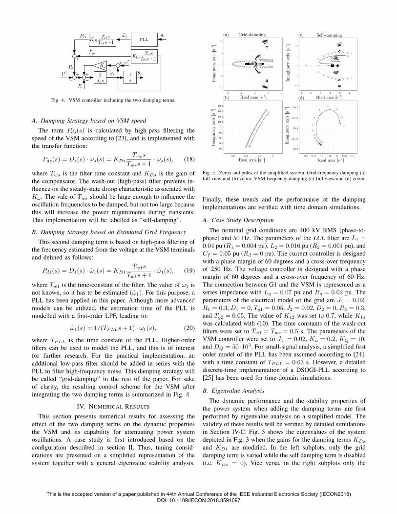
Fig. 5. Zeros and poles of the simplified system. Grid-frequency damping (a)full view and (b) zoom. VSM frequency damping (c) full view and (d) zoom.
Finally, these trends and the performance of the dampingimplementations are verified with time domain simulations.
A. Case Study Description
The nominal grid conditions are 400 kV RMS (phase-to-phase) and 50 Hz. The parameters of the LCL filter are L1 =0.04 pu (R1 = 0.004 pu), L2 = 0.016 pu (R2 = 0.001 pu), andCf = 0.05 pu (Rd = 0 pu). The current controller is designedwith a phase margin of 60 degrees and a cross-over frequencyof 250 Hz. The voltage controller is designed with a phasemargin of 60 degrees and a cross-over frequency of 60 Hz.The connection between G1 and the VSM is represented as aseries impedance with Lg = 0.07 pu and Rg = 0.02 pu. Theparameters of the electrical model of the grid are J1 = 0.02,R1 = 0.3, D1 = 0, Tg1 = 0.05, J2 = 0.02, D2 = 0, R2 = 0.3,and Tg2 = 0.05. The value of K12 was set to 0.7, while K1s
was calculated with (10). The time constants of the wash-outfilters were set to Tw1 = Tws = 0.5 s. The parameters of theVSM controller were set to JV = 0.02, Kω = 0.2, KQ = 10,and DQ = 50 ·103. For small-signal analysis, a simplified firstorder model of the PLL has been assumed according to [24],with a time constant of TPLL = 0.03 s. However, a detaileddiscrete-time implementation of a DSOGI-PLL according to[25] has been used for time-domain simulations.
B. Eigenvalue Analysis
The dynamic performance and the stability properties ofthe power system when adding the damping terms are firstperformed by eigenvalue analysis on a simplified model. Thevalidity of these results will be verified by detailed simulationsin Section IV-C. Fig. 5 shows the eigenvalues of the systemdepicted in Fig. 3 when the gains for the damping terms KDs
and KD1 are modified. In the left subplots, only the griddamping term is varied while the self damping term is disabled(i.e. KDs = 0). Vice versa, in the right subplots only the
This is the accepted version of a paper published in 44th Annual Conference of the IEEE Industrial Electronics Society (IECON2018) DOI: 10.1109/IECON.2018.8591097

020
4060
80100 0
2040
6080
1000
0.01
0.02
0.03
0.04
0.05
0.06
0.07D
ampi
ng fac
tor
[pu]
Parameter K [%]D1Parameter K [%]Ds
Fig. 6. Minimum damping factor of the electrical system when the parametersKD1 and KDs are modified.
0 2 4 6 8 10 12 14 16 18 200.994
0.996
0.998
1
Freq
uenc
y of
ar
ea 1
[pu
]
0 2 4 6 8 10 12 14 16 18 200.994
0.996
0.998
1
Freq
uenc
y of
area
2 [pu
]
0 2 4 6 8 10 12 14 16 18 20−0.1
−0.05
0
Time [s]
Pow
er b
etw
een
area
s 1
and
2 [p
u]
Grid model excluding the VSM
(a)
(b)
(c)
Fig. 7. Transient of the grid model when a 0.1 pu load is connected to G1Frequency of (a) G1 and (b) G2. (c) Power transferred between areas.
self damping term is modified while the grid damping term isdisabled (KD1 = 0). For the grid-damping, the resonant polesmove away from the imaginary axis when KD1 increases.However, there is a pair of complex poles that initially moveaway from instability, but return towards the unstable regionwhen the value of KD1 continue increasing. For the case ofself-damping (to the right), the damping of the complex polesslightly improves when the gain is increased, before the polesmove quickly towards the unstable region. This implies thatthe capability of damping the oscillations in the power systemis lower than for the grid-damping.
Fig. 6 shows the lowest damping factor of all the polesincluded in the system model as a function of the parametersKD1 and KDs. Damping increases up to a point where,suddenly, another eigenvalue reaches the stability limit. Thedamping of the closed-loop poles related to the inter-areaoscillation improves also for higher gains. However, as shownin the pole-zero analysis in Fig. 5 the low-frequency polesmove towards the unstable region when the gains increase.By observing the figure, it can be seen that a combination of
0 0.5 1 1.5 2 2.5 3 3.50.9994
0.9996
0.9998
1
1.0002
0 0.5 1 1.5 2 25 3 3.50.98
0.99
1
1.01
1.02
0 0.5 1 1.5 2 2.5 3 3.5−1
−0.5
0
0.5
1
Time [s]
(a)
(b)
(c)
Are
a 1
freq
uenc
y [p
u]V
SMfr
eque
ncy
[pu]
VSM
out
put
pow
er [pu
]
Excluding damping
Fig. 8. Performance of the system without damping terms. (a) Grid frequency,VSM (b) frequency, (c) output power, and (d) output current.
0 0.5 1 1.5 2 2.5 3 3.50.9994
0.9996
0.9998
1
1.0002
0.98
0.99
1
1.01
1.02
−1
−0.5
0
0.5
1
Time [s]
(a)
(b)
(c)
Are
a 1
freq
uenc
y [p
u]V
SMfr
eque
ncy
[pu]
VSM
out
put
pow
er [pu
]
Combined damping strategy
0 0.5 1 1.5 2 2.5 3 3.5
0 0.5 1 1.5 2 2.5 3 3.5
Fig. 9. Performance of the system with damping terms. (a) VSM outputcurrent, (b) frequency, (c) output power, and (d) output current.
KDs and KD1 provides the highest damping value and that thebest results are obtained when both parameters have similarvalues.
C. Time Domain Simulations
A simulation model of a HVDC-VSC terminal connectedto a grid is used to validate the proposed damping schemes.The model has been developed in the Matlab/Simulink en-vironment. The sampling and switching frequencies were 5kHz. Pulse width modulation with third harmonic injectionwas used. Classical decoupling equations were used for thecurrent and voltage controllers.
1) Oscillating grid: Fig. 7 shows the performance of theelectrical grid when the VSM is excluded and a 0.1 puload is connected to G1. Initially, the frequency of bothareas was constant. However, when the load was connected,
This is the accepted version of a paper published in 44th Annual Conference of the IEEE Industrial Electronics Society (IECON2018) DOI: 10.1109/IECON.2018.8591097

the low-frequency resonance of the grid was excited. Thisresult highlights the existence of a poorly damped oscillationbetween G1 and G2.
2) VSM excluding Damping: Fig. 8 shows the transientperformance of the electrical system when the VSM is con-nected to G1. In this case, the proposed damping terms are notincluded in the formulation of the VSM. Although the dynamicresponse is still poorly damped, it can be noticed that thesettling time of the oscillations has been significantly reducedcompared to the case in Section IV-C1. Thus, the results,demonstrate that already the droop gain of the VSM-basedcontrol can have a non-negligible influence on the dampingof the power system oscillations. However, the damping canbe further improved by utilisation of the additional dampingterms presented in this paper. It can also be noticed thateven though the a simplified model was used to analyse thelow-frequency oscillations, the oscillation frequency resultingfrom the simulations matches with the prediction from theeigenvalue analysis.
3) Damping of Oscillations: Fig. 9 shows the numericalresults obtained when the combined damping technique isapplied. Oscillations in the G1 and the VSM frequenciespresent in Fig. 8 have been clearly reduced. Also, the powerinjected from the VSM to grid is reduced compared to Fig. 8.
V. CONCLUSION
In this paper, two alternative implementations for dampingin a VSC HVDC controlled as a VSM have been presented andassessed comparatively. The first alternative requires only therotating speed of the VSM inertia, while the second is based onthe estimated frequency of the voltage measured at converterterminals. A reference power system with two generatorsinterconnected by a transmission line has been modelled andthe effect of a 150 MVA VSM on its dynamic behaviouris examined. Eigenvalue analysis and numerical simulationsdemonstrated that the VSM can effectively contribute to thedamping of power system oscillations. Although the dampingbased on estimated frequency has the strongest influence onthe power system oscillations, the highest impact is obtainedwhen both damping terms are present and optimally tuned.Both implementations in this paper adopt a first order high passfilter to isolate and identify the oscillatory mode. However,more advanced or higher order filters could be applied tofurther improve the performance of the system but this isconsidered as a topic for further research.
REFERENCES
[1] H. A. Peterson and P. C. Krause, “Damping of power swings in a parallelac and dc system,” IEEE Transactions on Power Apparatus and System,vol. 85, no. 12, pp. 1231–1239, December 1966.
[2] R. L. Cresap and W. A. Mittelstadt, “Small-signal modulation of thepacific hvdc intertie,” IEEE Transactions on Power Apparatus andSystem, vol. 95, no. 2, pp. 536–541, February 1976.
[3] A. M. Vural, “Contribution of high voltage direct current transmissionsystems to inter-area oscillation damping: A review,” Renewable andSustainable Energy Reviews, vol. 57, pp. 892–915, May 2016.
[4] L. Harnefors, N. Johansson, L. Zhang, and B. Berggren, “Interareaoscillation damping using active-power modulation of multiterminalhvdc transmissions,” IEEE Transactions on Power Systems, vol. 29,no. 5, pp. 2529–2538, Sept. 2014.
[5] R. H. Renner and D. V. Hertem, “Ancillary services in electric powersystems with hvdc grids,” IET Gener. Transm. Distrib., vol. 9, no. 11,pp. 1179–1185, November 2015.
[6] L. Harnefors, N. Johansson, and L. Zhang, “Impact on interarea modesof fast hvdc primary frequency control,” IEEE Transactions on PowerSystems, vol. 32, no. 2, pp. 1359–1358, March 2017.
[7] J. Zhu, C. D. Booth, G. P. Adam, A. J. Roscoe, and C. G. Bright,“Inertia emulation control strategy for vsc-hvdc transmission systems,”IEEE Trans. on Power Syst., vol. 28, no. 2, pp. 1227–1287, May 2013.
[8] E. Rakshani, D. Remon, A. M. Cantarellas, J. M. Garcia, and P. Ro-driguez, “Modeling and sensitivity analysis of vsp based virtual inertiacontroller in hvdc links of interconnected power systems,” ElectricPower System Research, vol. 141, pp. 246–263, Dec. 2016.
[9] E. Rakshani, D. Remon, A. M. Cantarellas, and P. Rodriguez, “Analysisof derivative control based virtual inertia in multi-area high-voltage di-rect current interconnected power systems,” IET Gener. Transm. Distrib.,vol. 10, no. 6, pp. 1458–1469, June 2016.
[10] S. D’Arco and J. A. Suul, “Virtual synchronous machines classificationof implementations and analysis of equivalence to droop controllers formicrogrids,” in Proc. IEEE PowerTech 2013, June 2013, pp. 1–7.
[11] S. D’Arco, J. A. Suul, and O. B. Fosso, “A virtual synchronousmachine implementation for distributed control of power converters insmartgrids,” El. Power Syst. Research, vol. 122, pp. 180–197, 2015.
[12] L. Zhang, L. Harnefors, and H. P. Nee, “Interconnection of two veryweak AC systems by VSC-HVDC links using power-synchronizationcontrol,” IEEE Trans. Pow. Sys., vol. 26, no. 1, pp. 344–355, Feb 2011.
[13] H. A. Alsiraji and R. El-Shatshat, “Comprehensive assessment of virtualsynchronous machine based voltage source converter controllers,” IETGen. Trans. Dist., vol. 11, no. 7, pp. 1762–1769, 2017.
[14] H. Zhao, Q. Yang, and H. Zeng, “Multi-loop virtual synchronousgenerator control of inverter-based dgs under microgrid dynamics,” IETGen. Trans. Dist., vol. 11, no. 3, pp. 795–803, 2017.
[15] T. Shintai, Y. Miura, and T. Ise, “Reactive power control for load sharingwith virtual synchronous generator control,” in Power Electronics andMotion Control Conference (IPEMC), 2012 7th International, vol. 2.IEEE, 2012, pp. 846–853.
[16] K.-i. Sakimoto, K. Sugimoto, and Y. Shindo, “Low voltage ride throughcapability of a grid connected inverter based on the virtual synchronousgenerator,” in Power Electronics and Drive Systems (PEDS), 2013 IEEE10th International Conference on. IEEE, 2013, pp. 1066–1071.
[17] S. Sakaeda, M. Asano, S. Sugimoto, S. Verma, R. Uda, and K. Kuroda,“Studies on stabilizing a massive pv penetrated power system usingvsg,” in Innovative Smart Grid Technologies Conference Europe (ISGT-Europe), 2017 IEEE PES. IEEE, 2017, pp. 1–6.
[18] J. Roldan-Perez, A. Rodrıguez-Cabero, and M. Prodanovic, “Harmonicvirtual impedance design for a synchronverter-based battery interfaceconverter,” in Renewable Energy Research and Applications (ICRERA),2017 IEEE 6th International Conference on. IEEE, 2017, pp. 774–779.
[19] M. Torres, L. Lopes, L. Moran, and J. Espinoza, “Self-tuning virtualsynchronous machine: A control strategy for energy storage systemsto support dynamic frequency control,” IEEE Transactions on EnergyConversion, vol. 29, no. 4, pp. 833–840, Dec 2014.
[20] Y. Hirase, K. Sugimoto, K. Sakimoto, and T. Ise, “Analysis of resonancein microgrids and effects of system frequency stabilization using a virtualsynchronous generator,” IEEE Journal of Emerging and Selected Topicsin Power Electronics, vol. 4, no. 4, pp. 1287–1298, Dec. 2016.
[21] J. Alipoor, Y. Miura, and T. Ise, “Power system stabilization usingvirtual synchronous generator with alternating moment of inertia,” IEEEJournal of Emerging and Selected Topics in Power Electronics, vol. 3,no. 2, pp. 451–458, June 2015.
[22] M. Blau and G. Weiss, “Synchronverters used for damping inter-areaoscillations in two-area power systems,” in International Conference onRenewable Energies and Power Quality (ICREPQ), March 2018.
[23] J. A. Suul, S. D’Arco, and G. Guidi, “A single-phase virtual synchronousmachine for providing vehicle-to-grid serviced from electric vehiclebattery chargers,” in Proceedings of the International Electric VehicleTechnology Conference Automotive Power Electronics, EVTeC APEJapan, May 2014, pp. 1–7.
[24] H. Awad, J. Svensson, and M. Bollen, “Tuning software phase-lockedloop for series-connected converters,” IEEE transactions on powerdelivery, vol. 20, no. 1, pp. 300–308, 2005.
[25] S. Golestan, M. Monfared, and F. D. Freijedo, “Design-oriented studyof advanced synchronous reference frame phase-locked loops,” IEEETrans. on Power Electronics, vol. 28, no. 2, pp. 765–778, Feb 2013.
This is the accepted version of a paper published in 44th Annual Conference of the IEEE Industrial Electronics Society (IECON2018) DOI: 10.1109/IECON.2018.8591097