virtual wireless controller deployment guide - fortinet · hardware platform provided that the...
TRANSCRIPT

Copyright © 2017 Fortinet Networks, Inc. All rights reserved.
Virtual Wireless Controller Deployment Guide 2017
Release 8.3.3

Copyright © 2017 Fortinet Networks, Inc. All rights reserved.
Copyright© 2017 Fortinet, Inc. All rights reserved. Fortinet® and certain other marks are registered trademarks of Fortinet, Inc., in the U.S. and other
jurisdictions, and other Fortinet names herein may also be registered and/or common law trademarks of Fortinet. All other product or company names
may be trademarks of their respective owners. Performance and other metrics contained herein were attained in internal lab tests under ideal conditions,
and actual performance and other results may vary. Network variables, different network environments and other conditions may affect performance
results. Nothing herein represents any binding commitment by Fortinet, and Fortinet disclaims all warranties, whether express or implied, except to the
extent Fortinet enters a binding written contract, signed by Fortinet's General Counsel, with a purchaser that expressly warrants that the identified product
will perform according to certain expressly-identified performance metrics and, in such event, only the specific performance metrics expressly identified in
such binding written contract shall be binding on Fortinet. For absolute clarity, any such warranty will be limited to performance in the same ideal
conditions as in Fortinet's internal lab tests. In no event does Fortinet make any commitment related to future deliverables, features or development, and
circumstances may change such that any forward-looking statements herein are not accurate. Fortinet disclaims in full any covenants, representations,
and guarantees pursuant hereto, whether express or implied. Fortinet reserves the right to change, modify, transfer, or otherwise revise this publication
without notice, and the most current version of the publication shall be applicable.

Copyright © 2017 Fortinet Networks, Inc. All rights reserved.
For assistance, contact Fortinet Customer Service and Support 24 hours a day at +1 408-542-7780, or by using one of the local contact
numbers, or through the Support portal at https://support.fortinet.com/
Fortinet Customer Service and Support provide end users and channel partners with the following:
Technical Support
Software Updates
Parts replacement service
Copyright © 2017 Fortinet Networks, Inc. All rights reserved.
Overview
About Fortinet Virtual Controllers
The Virtual Controllers are a software version of the Fortinet Appliance Controllers that are installed on an existing hardware platform provided that the platform implements a supported virtual hosting software solution.
The Virtual Controllers are built on the same System Director operating system that powers the Fortinet WLAN Controller for the enterprise delivering superior reliability, scalability and predictability for WLAN deployments. They run on the widely deployed VMware vSphere, RHEL Kernel-based Virtual Machine (KVM), and Windows based Hyper-V virtualization platforms installed on industry-standard hardware.
When a virtual controller is purchased, the controller image can be downloaded from the Customer Support Portal and, once properly installed, can be configured just as a standard physical machine.
Advantages of Fortinet Virtual Controllers These are some of the advantages of the Fortinet Virtual Controllers.
Flexibility in hardware selection based on your requirements.
Reduced cost, space requirements, and other overheads since multiple appliances can be replaced with single hardware running multiple instances of the controllers, FWLM Management; which is a web based application suite which manages controllers and access points mapped to the network to provide real-time data that enables centralized and remote monitoring of the network, and Fortinet Connect; which is a complete provisioning, management, and reporting system that provides temporary network access for guests, visitors, contractors, consultants, or customers..
Independent and mutually exclusive instances allow administrators to use multiple virtual controllers to manage different locations or scale the deployment using the same hardware.
Enable features provided by the virtualization software, including High Availability, failover protection, and ease of migration. VMWare vMotion Storage and Snapshots are supported. Hyper-V specific features (Snapshot, Failover (HA), Replication, Hot swapping) are not supported.
Centralized control and visibility at every level of the virtual infrastructure.

Copyright © 2017 Fortinet Networks, Inc. All rights reserved.
Supported Hardware Configuration
The Fortinet Virtual Controller Models are available as the MC-VE series and the FWC-VM series.
MC-VE Series Virtual Controllers
This table lists the controller models available for the MC-VE Series Virtual Controllers and their corresponding requirements.
Models MC1550-VE MC3200-VE MC4200-VE (1G) MC4200-VE (10G)
Scale AP 50 200 500 500
Clients 1250 2500 6250 6250
vCPU 2 3 4 4
Memory 2GB 2GB 4GB 4GB
vNIC 1-2 1-2 1-4 1-2
Disk Space 2GB 2GB 2GB 2GB
FWC-VM Series Virtual Controllers
This table lists the controller models available for the new FWC-VM Series Virtual Controllers and their corresponding requirements.
Models FWC-VM-50 FWC-VM200 FWC-VM500 FWC-VM-1000 FWC-VM-3000
Scale AP 50 200 500 1000 3000
Clients 1250 2500 6250 10000 30000
vCPU 4 4 8 24 48
Memory
4GB 8GB 16GB 32GB 64GB
vNIC 1-4 1-4 1-4 1-4 1-8
Disk Space 16GB (Fixed)
16GB (Fixed)
16GB (Fixed) 16GB (Fixed) 16GB (Fixed)
Fortinet Virtual Controller Deployment Modes The MC-VE series and the FWC-VM series Virtual Controllers can be deployed in different modes.
The following list summarizes the recommended 3rd party software requirements for installing and configuring Fortinet Virtual Controllers.
Copyright © 2017 Fortinet Networks, Inc. All rights reserved.
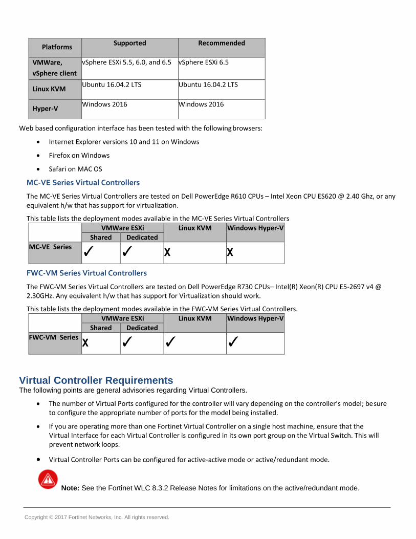
Platforms Supported Recommended
VMWare, vSphere client
vSphere ESXi 5.5, 6.0, and 6.5 vSphere ESXi 6.5
Linux KVM Ubuntu 16.04.2 LTS Ubuntu 16.04.2 LTS
Hyper-V Windows 2016 Windows 2016
Web based configuration interface has been tested with the following browsers:
Internet Explorer versions 10 and 11 on Windows
Firefox on Windows
Safari on MAC OS
MC-VE Series Virtual Controllers
The MC-VE Series Virtual Controllers are tested on Dell PowerEdge R610 CPUs – Intel Xeon CPU ES620 @ 2.40 Ghz, or any equivalent h/w that has support for virtualization.
This table lists the deployment modes available in the MC-VE Series Virtual Controllers
VMWare ESXi Linux KVM Windows Hyper-V
Shared Dedicated
MC-VE Series ✓ ✓ x x
FWC-VM Series Virtual Controllers
The FWC-VM Series Virtual Controllers are tested on Dell PowerEdge R730 CPUs– Intel(R) Xeon(R) CPU E5-2697 v4 @ 2.30GHz. Any equivalent h/w that has support for Virtualization should work.
This table lists the deployment modes available in the FWC-VM Series Virtual Controllers.
VMWare ESXi Linux KVM Windows Hyper-V
Shared Dedicated
FWC-VM Series x ✓ ✓ ✓
Virtual Controller Requirements The following points are general advisories regarding Virtual Controllers.
The number of Virtual Ports configured for the controller will vary depending on the controller’s model; be sure to configure the appropriate number of ports for the model being installed.
If you are operating more than one Fortinet Virtual Controller on a single host machine, ensure that the Virtual Interface for each Virtual Controller is configured in its own port group on the Virtual Switch. This will prevent network loops.
Virtual Controller Ports can be configured for active-active mode or active/redundant mode.
Note: See the Fortinet WLC 8.3.2 Release Notes for limitations on the active/redundant mode.

Copyright © 2017 Fortinet Networks, Inc. All rights reserved.
Common Terminology
The following are some of the Networking VMware elements that will be used to configure the Fortinet Virtual Controller to operate in VMware environment:
vSwitch
This is a virtual switch, similar to a physical switch, performs functions including the Layer 2 forwarding engine, VLAN tagging, stripping, and filtering, security, checksum, and segmentation. The vSwitch links VMs to each other locally as well as to physical networks. A controller VE should connect to a vSwitch through virtual machine port groups.
Port Groups
Port groups are not VLANs. They are configuration templates for the vNIC ports on the vSwitch. Administrators can set specific QoS, security policies, and VLANs by port group. This is where you should enable promiscuous mode (and not on the vSwitch).
Promiscuous Mode (VMWare ESXi only)
Fortinet Virtual Controllers are typically deployed as an in-line device on the data path and all the packets pass through the controller. Because of this, it needs to operate in Promiscuous mode. vSphere’s vSwitch and port group properties have the option to enable promiscuous mode. Again, it is highly recommended to enable this on the port group.
VM-NIC Queues Usage
The field VM NIC Queues in the sh controller command indicates the value assigned to a Controller for better performance, based on different platforms/hypervisors. This field mainly applies for the Virtual Controller Instance’s deployed using VMWare and Linux KVM and not for Hyper-V. For Virtual Controller models deployed using Hyper-V Platform, this field is not applicable and shows N for all Controller models.
For the Virtual Controller models deployed using different platforms, these are the VM NIC Queues values.
Platforms FWC-VM-50 FWC-VM-200 FWC-VM-500 FWC-VM-1000 FWC-VM-3000
VMWare 4 4 8 8 8
Linux KVM 2 2 4 8 16
Hyper-V N N N N N

Copyright © 2017 Fortinet Networks, Inc. All rights reserved.
Deploying Fortinet Virtual Controllers with VMWare ESXi
Pre-requisites For deployment and management of the Virtual Controller, you will need to download any of these VMware suites to the workstation:
Single ESXi server management − Use VMware vSphere Client.
Multiple ESXi servers requires vCenter − Advance features are also tied with vCenter which needs separate licenses (vMotion, and so on).
Fortinet Virtual Controllers can be deployed in these 2 modes in a VMWare setup.
Note: Fortinet recommends that you deploy the Fortinet Virtual Controllers in the dedicated mode. This mode of deployment achieves the maximum throughput for each Controller model, especially when using the APs in Tunnel mode where all the traffic will be tunneled by the APs to the controller and then to the Network.
Dedicated Deployment: Dedicated NIC, vSwitch and vPort Group
(MC-VE Series Only) Shared Deployment: Sharing NIC with existing vSwitch
Start the VMware vSphere Client, and log in to the ESXi server. Go to Configuration and click Networking.
As you can see, there are existing 2 VM running on the host, using the same vSwitch0 and same Virtual Machine port Group. The vSwitch is also used by the vKernel Port that is responsible for the ESXi management.
Downloading the Virtual Controller Package File You can download the virtual controller packages from the Fortinet Customer Support website. To access the support website you need a Fortinet Customer Support account. The file name is, forti-x.x-xbuild-0-x86_64.ova, where x.x-x is the release version number. For example, 8.3.2.

Copyright © 2017 Fortinet Networks, Inc. All rights reserved.
Configuring Dedicated Deployment
In this deployment, we will be using an added NIC card with 2 Gig Ethernet ports as shown in the Network Adapters wizard.

Copyright © 2017 Fortinet Networks, Inc. All rights reserved.
These 2 Gig Interface are connected to a Switch that support Link Aggregation (LAG). It is assumed in this procedure that the LAG is created on the switch and has the appropriate VLAN configuration. Refer to the VLAN deployment guide for the Fortinet Controllers.
1. Create a new Virtual Switch: Go to Networking and click Add Networking…
2. Select Virtual Machine and click Next.
Create a vSwitch and assign the dedicated physical NIC. Click Next and provide and label for the vSwitch, for example, FWC-VM-50.
3. For VLAN ID, select All (4095), if you are using Trunk port on the switch. Click Next and then Finish to complete the vSwitch creation.

Copyright © 2017 Fortinet Networks, Inc. All rights reserved.
4. The end result of adding the vSwitch will result in vSwitch 1 and a virtual machine port group named MC3200 vSwitch.
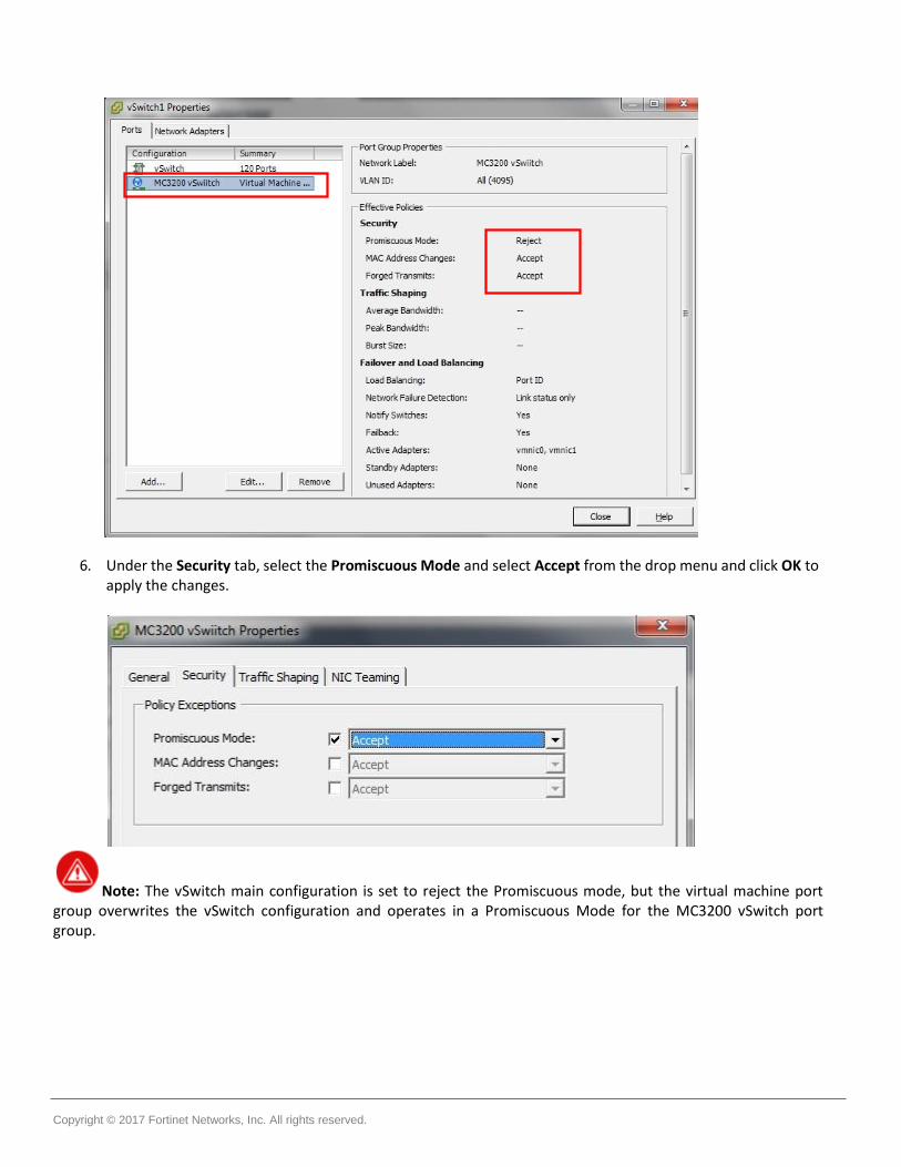
5. Click on vSwitch1 Properties, select MC3200 vSwitch port group and click Edit.
Copyright © 2017 Fortinet Networks, Inc. All rights reserved.
6. Under the Security tab, select the Promiscuous Mode and select Accept from the drop menu and click OK to apply the changes.
Note: The vSwitch main configuration is set to reject the Promiscuous mode, but the virtual machine port group overwrites the vSwitch configuration and operates in a Promiscuous Mode for the MC3200 vSwitch port group.

Copyright © 2017 Fortinet Networks, Inc. All rights reserved.
Each vNIC has to be a part of a different Vswitch connected to different physical ports. Now that the structure is ready, start installing the OVA template into the VMware host.
Installing the Virtual Controller 1. Go to File and click Deploy OVF Template… in order to start the installation.
2. Browse to the location of the OVA template that you downloaded from Fortinet Support page and click Next.

Copyright © 2017 Fortinet Networks, Inc. All rights reserved.
3. Click Next and enter a Name for the Virtual Controller, for example, MC3200VE-North Campus.
4. Configure the following:
Resource Pool
Storage
Disk Format, use the default for the disk format, Thick Provisioning Lazy Zereod.
Network Mapping.
5. Click Finish in the Ready to Complete wizard.

Copyright © 2017 Fortinet Networks, Inc. All rights reserved.
The upload and installation of the Virtual Controller will start, the time varies according to the network bandwidth between the vSphere Client and the ESXi Host. You should get a Completed Successfully message at the end.
Copyright © 2017 Fortinet Networks, Inc. All rights reserved.

Copyright © 2017 Fortinet Networks, Inc. All rights reserved.
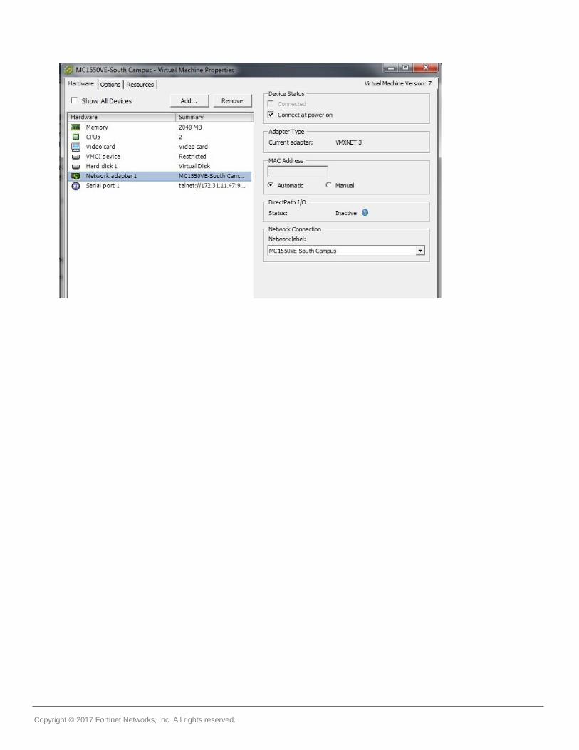
Configuring Virtual Controller Settings
After creating the virtual controller, configure the virtual machine settings and add the needed network adapters.
1. Select the Virtual Controller created above (MC3200VE-North Campus) and click Edit virtual machine settings in the Getting Started tab.
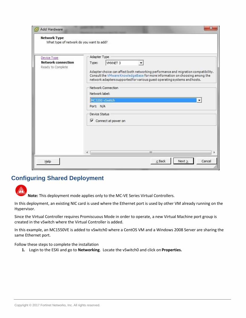
2. Click on Add and select Ethernet Adapter.
Click Next, choose VMXNET 3 and choose the Network Connection (port group) created above (MC3200 vSwitch) and then click Next and Finish. (Other drivers supported are E1000, VMXNET and VMXNET 2. The latest VMXNET 3 is needed to support the 10GB connection for the Virtual Controller.
3. Use 1 or more Ethernet adapters as recommended in section Supported Hardware Configuration. Adding more than 1 will cause duplicate packets, see the FortiWLC Release Notes for limitations.
Copyright © 2017 Fortinet Networks, Inc. All rights reserved.
Configuring Shared Deployment
Note: This deployment mode applies only to the MC-VE Series Virtual Controllers.
In this deployment, an existing NIC card is used where the Ethernet port is used by other VM already running on the Hypervisor.
Since the Virtual Controller requires Promiscuous Mode in order to operate, a new Virtual Machine port group is created in the vSwitch where the Virtual Controller is added.
In this example, an MC1550VE is added to vSwitch0 where a CentOS VM and a Windows 2008 Server are sharing the same Ethernet port.
Follow these steps to complete the installation 1. Login to the ESXi and go to Networking. Locate the vSwitch0 and click on Properties.

Copyright © 2017 Fortinet Networks, Inc. All rights reserved.
The vSwitch has the Promiscuous Mode set to Reject.
2. Click on Add, select Virtual Machine and click Next.
3. Add a Network label to the Virtual Machine Port Group (MC1550VE-South Campus), click Next and then Finish.

Copyright © 2017 Fortinet Networks, Inc. All rights reserved.
Select the newly created port group and Edit the settings. Under the Security tab, change the Promiscuous Mode to Accept and click OK.
Now that the infrastructure is ready, you can install the OVA as described in the previous section. Add the Network Adapter and map the Virtual Controller Ethernet to the Virtual Machine Port Group that was created (MC1550VE-South Campus).
Copyright © 2017 Fortinet Networks, Inc. All rights reserved.

Copyright © 2017 Fortinet Networks, Inc. All rights reserved.
Starting the Virtual Controller
Select the Controller and go to the Console Tab and Start the VM by clicking on the Power On button or (Ctrl+b). The Virtual Controller will start and you will see the entire startup message that you will typically found in a Hardware Controller.
The first boot might take few minutes longer to boot up if no DHCP server is available as the controller will try to get an IP address from the DHCP server. Please refer to the Controller SD documentation to complete the controller installation.
Recommended VMware ESXi Host Settings Fortinet recommends the following VM configurations and global host settings for enhanced Controller performance. VM Configuration Settings
CPU affinity - In servers where the available physical cores (i.e. half of HT CPUs) are more than the required cores for Controllers, set the CPU affinity such that no two vCPUs are scheduled on the same physical core by the VMKernel.
To set the CPU range, go to Edit Settings ->Virtual Hardware -> CPU -> Scheduling Affinity.
Latency Sensitivity - Set the Latency sensitivity to High, to do so, go to Edit Settings -> VM Options -> Advanced -> Latency Sensitivity.
Virtual NIC settings - Disable virtual interrupt coalescing, to do so, go to Edit Settings -> Options tab -> Advanced -> Configuration Parameters and add an entry for ethernetX.coalescingScheme with the value disabled.
Global Host Settings
Physical NIC settings – Disable the interrupt moderation/coalescing. Run the esxcli system module parameters set -m ixgbe -p "InterruptThrottleRate=0" CLI command. This is applicable to Intel 10G with ixgbe driver, that is, chipsets Intel 82599 and is not applicable or i40en based drivers. Run the esxcli network nic list CLI command to find the list of drivers.
Set the /Net/MaxNetifTxQueueLen global parameter to 10000 (default is 2000). Run the esxcli system settings advanced set -o /Net/MaxNetifTxQueueLen -i=10000 CLI command.
Set the /Net/NetVMTxType global parameter to 3 (applicable only for ESXi 6.5). Run the esxcli system settings advanced set -o /Net/NetVMTxType -i=3 CLI command. This allocates multiple Tx world, that is, 1 per queue.
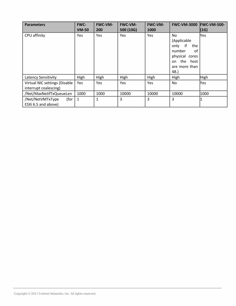
These are the parameters for different Controller models.
Copyright © 2017 Fortinet Networks, Inc. All rights reserved.
Parameters FWC-VM-50
FWC-VM-200
FWC-VM-500 (10G)
FWC-VM-1000
FWC-VM-3000 FWC-VM-500-(1G)
CPU affinity Yes Yes Yes Yes No (Applicable only if the number of physical cores on the host are more than 48.)
Yes
Latency Sensitivity High High High High High High
Virtual NIC settings (Disable interrupt coalescing)
Yes Yes Yes Yes No Yes
/Net/MaxNetifTxQueueLen 1000 1000 10000 10000 10000 1000
/Net/NetVMTxType (for ESXi 6.5 and above)
1 1 3 3 3 1

Copyright © 2017 Fortinet Networks, Inc. All rights reserved.
Deploying Fortinet Virtual Controllers with Linux KVM
Pre-requisites For deployment and management of the Virtual Controller on Linux KVM, install the following 3rd party software.
Install Ubuntu v16.04 LTS server.
Install KVM on the Ubuntu LTS server.
Create an open Vswitch with KVM.
Install Virtual Machine Manage (virt-manager) to create and manage guest virtual machines.
Note: To accomplish the pre-requisites refer to the respective 3rd party documentation.
Downloading the Virtual Controller Package File You can download the virtual controller packages from the Fortinet Customer Support website. To access the support website you need a Fortinet Customer Support account. The file name is, forti-x.x-xbuild-0-x86_64.img.KVM.zip, where x.x-x is the release version number. For example, 8.3.2.
Installing Linux KVM 1. Install Ubuntu 16.04.2 64-bit Desktop version.
2. Run the apt-get install openssh-server command to install openssh utility.
Now, you should be able to ssh to the machine.
3. Run the egrep -c '(vmx|svm)' /proc/cpuinfo command to check whether the system supports Virtualization or not.
If the output is 0, then the system does not support Virtualization. If the output is greater than 0 it means your system is set and ready to go for KVM installation.
4. Run the following commands to install openvswitch which is used for tagging and untagging the vlans created.
apt-get install openvswitch openvswitch-common openvswitch-switch
/etc/init.d/openvswitch-switch start
5. Run the following commands to create a virtual-bridge.
ovs-vsctl add-br <bridge-name:(user-defined)>
ovs-vsctl port <port-name:(user-defined) <eth-intf: name of the physical Ethernet port>
ovs-vsctl set port vnet0 trunks=0,168,169.
In this command 168 and 169 are tagged vlans and 0 is a mandatory argument which specifies the native-vlan.
dhclient <<bridge-name:(user-defined)>
6. Run the ovs-vsctl show command to see the virtual switch created. This is a sample command output:
root@automation-HP-406-G1-MT:~# ovs-vsctl show 52690264-a2da-4a63-86e9-c8ceabf9be72 Bridge "N164-T168-T169" (N164-T168-T169:Bridge-name) Port "N164-T168-T169" (N164-T168-T169:port--name) Interface "N164-T168-T169" type: internal Port "enp3s0" (enp3s0:physical Ethernet port name) Interface "enp3s0" Port "vnet0" trunks: [0, 168, 169] Interface "vnet0" ovs_version: "2.5.0"
7. Run the sudo apt-get install qemu-kvm libvirt-bin ubuntu-vm-builder bridge-utils command to install KVM.
Copyright © 2017 Fortinet Networks, Inc. All rights reserved.
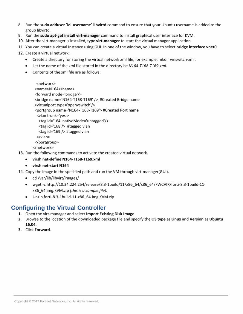
8. Run the sudo adduser `id -username` libvirtd command to ensure that your Ubuntu username is added to the group libvirtd.
9. Run the sudo apt-get install virt-manager command to install graphical user interface for KVM. 10. After the virt-manager is installed, type virt-manager to start the virtual manager application.
11. You can create a virtual Instance using GUI. In one of the window, you have to select bridge interface vnet0.
12. Create a virtual network:
Create a directory for storing the virtual network xml file, for example, mkdir vmswitch-xml.
Let the name of the xml file stored in the directory be N164-T168-T169.xml.
Contents of the xml file are as follows:
<network>
<name>N164</name> <forward mode='bridge'/> <bridge name='N164-T168-T169' /> #Created Bridge name <virtualport type='openvswitch'/> <portgroup name='N164-T168-T169'> #Created Port name <vlan trunk='yes'> <tag id='164' nativeMode='untagged'/> <tag id='168'/> #tagged vlan <tag id='169'/> #tagged vlan </vlan> </portgroup> </network>
13. Run the following commands to activate the created virtual network.
virsh net-define N164-T168-T169.xml
virsh net-start N164
14. Copy the image in the specified path and run the VM through virt-manager(GUI).
cd /var/lib/libvirt/images/
wget -c http://10.34.224.254/release/8.3-1build/11/x86_64/x86_64/FWCVIR/forti-8.3-1build-11-
x86_64.img.KVM.zip (this is a sample file).
Unzip forti-8.3-1build-11-x86_64.img.KVM.zip
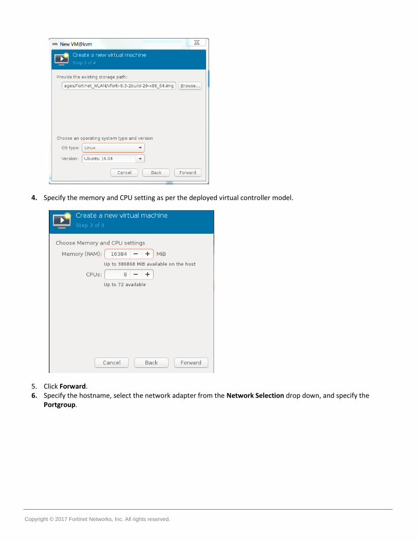
Configuring the Virtual Controller 1. Open the virt-manager and select Import Existing Disk Image. 2. Browse to the location of the downloaded package file and specify the OS type as Linux and Version as Ubuntu
16.04. 3. Click Forward.
Copyright © 2017 Fortinet Networks, Inc. All rights reserved.
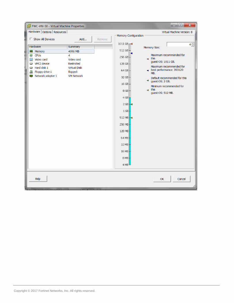
4. Specify the memory and CPU setting as per the deployed virtual controller model.
5. Click Forward. 6. Specify the hostname, select the network adapter from the Network Selection drop down, and specify the
Portgroup.

Copyright © 2017 Fortinet Networks, Inc. All rights reserved.
7. Click Finish. 8. In the CPUs settings, configure the Model as Nehalem. Click Apply.
9. In the VirtIO Disk1, under Advanced options, select the Disk bus as IDE. Click Apply.

Copyright © 2017 Fortinet Networks, Inc. All rights reserved.
10. In the NIC settings, specify the Network source, Portgroup, and Device model as virtio. Click Apply.
The Virtual Controller deployment is complete.
Recommended Linux KVM Host Settings Fortinet recommends the following host settings for enhanced Controller performance.

Copyright © 2017 Fortinet Networks, Inc. All rights reserved.
Disable the offload settings like GSO, GRO, TSO, and UFO for all ports. Run the ethtool -K <eth dev> gso off lro off tso off ufo off command.
Set the ring descriptor size (ethtool -G <eth dev> 4096) to the maximum limit (4096) for all ports.
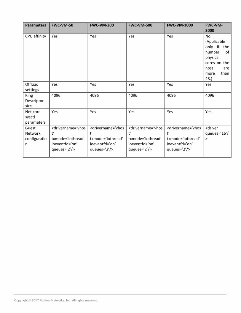
Set net.core.netdev_budget to 600 and net.core.netdev_max_backlog to 60000. The commands in the above steps could be set in /etc/rc.local so that configuration is retained on a reboot of the host. Based on the VM model, modify the guest xml file and add below line in each interface in xml file.as follows:
o FWC-VM-50: <driver name='vhost' txmode='iothread' ioeventfd='on' queues=’2'/> o FWC-VM-200: <driver name='vhost' txmode='iothread' ioeventfd='on' queues=’2'/> o FWC-VM-500: <driver name='vhost' txmode='iothread' ioeventfd='on' queues=‘4'/> o FWC-VM-1000: <driver name='vhost' txmode='iothread' ioeventfd='on' queues='8'/> o FWC-VM-3000: <driver queues=‘16'/>
This is an example of FWC-VM-200 configuration.
In servers where the available physical cores, that is, half of HT CPUs, are more than the number of vhost kernel threads, set the IRQ affinity for vhost kernel threads. For example, in 1000D each port has 8 queues, hence, there are 32 total vhost threads. Use this script to set the affinity for vhost kernel threads for 1000D VM on Dell PowerEdge R730 (for other hosts, the configuration would be different).
#!/bin/bash cpids=`ps -ef | grep [v]host- | awk '{ print $2 }' | xargs` echo $cpids for cpid in $cpids; do taskset -pc 36-71 $cpid echo $cpid done This script sets the CPU affinity for vhost kernel threads from CPUs 36-71.
Copyright © 2017 Fortinet Networks, Inc. All rights reserved.
Parameters FWC-VM-50 FWC-VM-200 FWC-VM-500 FWC-VM-1000 FWC-VM-3000
CPU affinity Yes Yes Yes Yes No (Applicable only if the number of physical cores on the host are more than 48.)
Offload settings
Yes Yes Yes Yes Yes
Ring Descriptor size
4096 4096 4096 4096 4096
Net.core sysctl parameters
Yes Yes Yes Yes Yes
Guest Network configuration
<drivername=‘vhost’ txmode=’iothread’ ioeventfd=’on’ queues=’2’/>
<drivername=‘vhost’ txmode=’iothread’ ioeventfd=’on’ queues=’2’/>
<drivername=‘vhost’ txmode=’iothread’ ioeventfd=’on’ queues=’2’/>
<drivername=‘vhost’ txmode=’iothread’ ioeventfd=’on’ queues=’2’/>
<driver queues=’16’/>
Copyright © 2017 Fortinet Networks, Inc. All rights reserved.
Deploying Fortinet Virtual Controllers on Hyper-V
Note: FWC-VM-1000 & FWC-VM-3000 are not supported on the Windows Hyper-V platform.
Pre-requisites For deployment and management of the Virtual Controller on Hyper-V, install the following 3rd party software.
Install Windows server 2016.
Install the Hyper-V role.
Create a Hyper-V Vswitch.
Note: To accomplish the pre-requisites refer to the respective 3rd party documentation.
Downloading the Virtual Controller Package File You can download the virtual controller packages from the Fortinet Customer Support website. To access the support website you need a Fortinet Customer Support account. The file name is, forti-x.x-xbuild-0-x86_64.vhd.hv.zip, where x.x-x is the release version number. For example, 8.3.2.
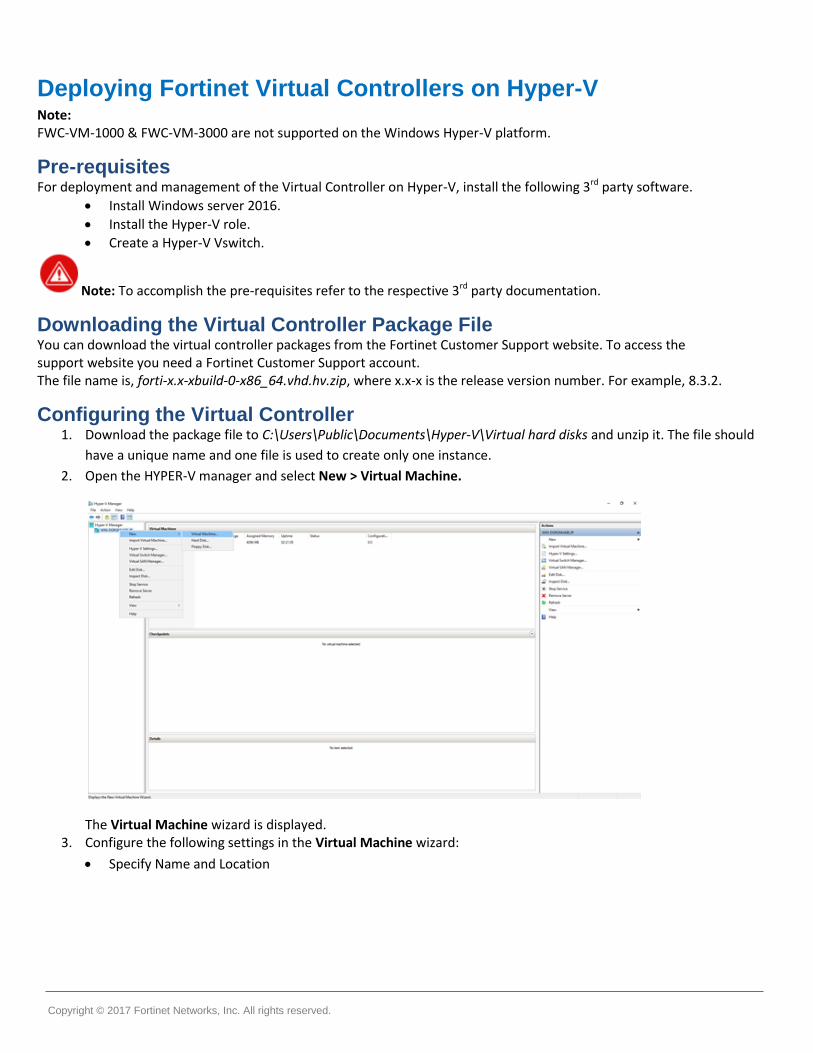
Configuring the Virtual Controller 1. Download the package file to C:\Users\Public\Documents\Hyper-V\Virtual hard disks and unzip it. The file should
have a unique name and one file is used to create only one instance.
2. Open the HYPER-V manager and select New > Virtual Machine.
The Virtual Machine wizard is displayed. 3. Configure the following settings in the Virtual Machine wizard:
Specify Name and Location

Copyright © 2017 Fortinet Networks, Inc. All rights reserved.
Specify Generation – Select Generation 1.
Assign Memory (Supported Hardware Configuration)

Copyright © 2017 Fortinet Networks, Inc. All rights reserved.
Configure Networking
Connect Virtual Hard Disk – Select Use an existing virtual hard disk

Copyright © 2017 Fortinet Networks, Inc. All rights reserved.
4. Click Finish. The virtual machine is listed.
5. Select the newly created virtual machine and double-click. The settings are displayed.
6. Specify the Number of virtual processors in the Processor settings.
7. Select Enable MAC address spoofing in the Advanced Features settings to establish wireless connectivity.
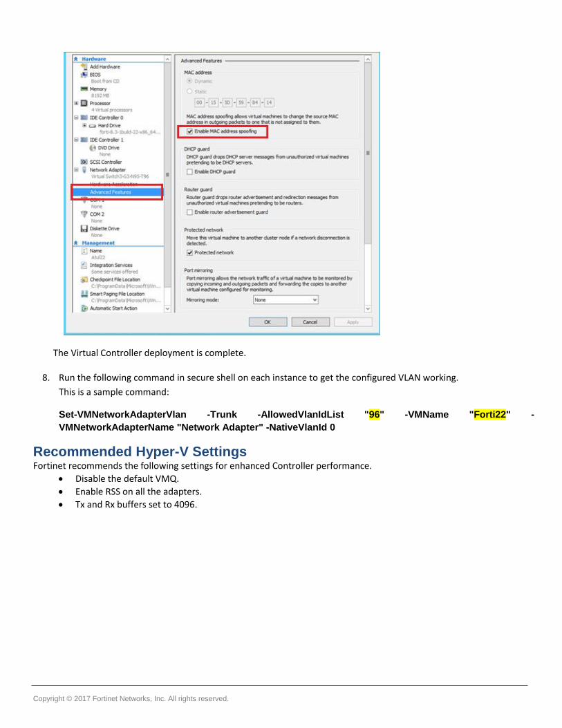
Copyright © 2017 Fortinet Networks, Inc. All rights reserved.
The Virtual Controller deployment is complete.
8. Run the following command in secure shell on each instance to get the configured VLAN working.
This is a sample command:
Set-VMNetworkAdapterVlan -Trunk -AllowedVlanIdList "96" -VMName "Forti22" -
VMNetworkAdapterName "Network Adapter" -NativeVlanId 0
Recommended Hyper-V Settings Fortinet recommends the following settings for enhanced Controller performance.
Disable the default VMQ.
Enable RSS on all the adapters.
Tx and Rx buffers set to 4096.

Copyright © 2017 Fortinet Networks, Inc. All rights reserved.
License Management for Fortinet Virtual Controllers This section assumes you have already received your entitlement for the Fortinet Virtual Controller you ordered. Along with the entitlement that allows you to obtain the license for your instance, you would also have received instructions on where to download the right version of the software for the model you ordered. Register your product at the Fortinet Support Portal and use the registration key and system ID to obtain a license file.
Note: Obtain the license only after completing the installation of the Virtual Controller. Contact the Forticare Support with the details entailed in the following sections to obtain the license.
FWC-VM Series Virtual Controllers After completing installation of the Virtual Controller, login to the controller and run the setup command to generate the system-id. Perform the following steps to obtain the license.
1. Run the setup command on the Controller to generate the system-id, configure the hostname, and configure the static IP address of the Controller, to ensure that the IP address does not change as the system-id/license is mapped to the IP address of the Controller.
2. Save the configuration. The Controller restarts. 3. Run the show system-id command to obtain the system-id. 4. Share the Virtual Controller model details and system-id with the Forticare Support team. 5. Configure the Virtual Controller instance with the required resources (Supported Hardware Configuration) as per
the model for which the license has been generated. 6. Install the license from the GUI (See section Importing and installing a License) OR from the CLI (Configuration
Terminal mode => vm-license scp://username@<Your file server IP Address>:<license filename>) 7. Reboot the Controller to apply the changes as per the generated license.
Note: A freshly installed system boots up as FWC-VM-50 with default license valid for 30 days.
System-id is not get generated until you run the setup command on a fresh instance.
System-id is coupled with the IP address. Hence, any change in the IP address generates a new system-id thereby failing validation of the older license. In this case, a new license is required. Changing the IP address via CLI followed by a reboot to activate the new IP address does not generate a new system-id. Hence, license validation fails and the Controller is once again the FWC-VM-50 model. Therefore, use only the setup command to change the Controller IP address.
After the license is invalidated due to a change in the system-id and the controller is once again a FWC-VM-50 model, ensure that you delete the invalid license for the Controller to function properly. Else, the Controller reboots after every one hour.
Importing and Installing a License Perform these steps to obtain the license using the GUI.
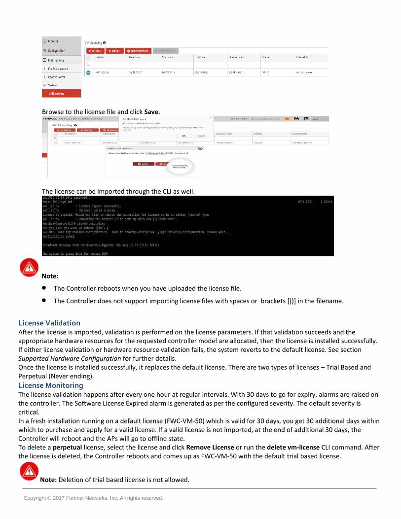
1. Navigate to Maintenance > System > VM Licensing This image displays a freshly installed system which has a default license (trial based) valid for 30 days from the license issued date.
2. In the VM Licensing wizard, click Import to add a license. By default, this page lists the license available on the system which includes details on the Virtual Controller model.
Copyright © 2017 Fortinet Networks, Inc. All rights reserved.
Browse to the license file and click Save.
The license can be imported through the CLI as well.
Note:
The Controller reboots when you have uploaded the license file. The Controller does not support importing license files with spaces or brackets [()] in the filename.
License Validation After the license is imported, validation is performed on the license parameters. If that validation succeeds and the appropriate hardware resources for the requested controller model are allocated, then the license is installed successfully. If either license validation or hardware resource validation fails, the system reverts to the default license. See section Supported Hardware Configuration for further details. Once the license is installed successfully, it replaces the default license. There are two types of licenses – Trial Based and Perpetual (Never ending).
License Monitoring The license validation happens after every one hour at regular intervals. With 30 days to go for expiry, alarms are raised on the controller. The Software License Expired alarm is generated as per the configured severity. The default severity is critical. In a fresh installation running on a default license (FWC-VM-50) which is valid for 30 days, you get 30 additional days within which to purchase and apply for a valid license. If a valid license is not imported, at the end of additional 30 days, the Controller will reboot and the APs will go to offline state. To delete a perpetual license, select the license and click Remove License or run the delete vm-license CLI command. After the license is deleted, the Controller reboots and comes up as FWC-VM-50 with the default trial based license.
Note: Deletion of trial based license is not allowed.
Copyright © 2017 Fortinet Networks, Inc. All rights reserved.
MC-VE Series Virtual Controllers After completing installation of the Virtual Controller, login to the controller and run the show system-id command.
You will need the output of this command along with the entitlement ID to generate the license key for your Virtual controller.
The system-id parameter is computed based on the configuration gathered through the setup process in the Controller or entered using the Ez-Setup wizard. The following fields are captured through the setup process.
Time zone Hostname IP Address of Controller's primary interface IP Mask of Controller's primary interface Gateway Address of Controller's primary interface Country Code VC model
Share the Virtual Controller model details, system-id, and the license validity period (or permanent license) with the Forticare Support team. Any subsequent changes to the parameters above would warrant you to get a new license.
Copyright © 2017 Fortinet Networks, Inc. All rights reserved.
Fortinet Virtual Controller Management
Like any conventional Hardware Controller that Fortinet offers, the Virtual Controller can be managed by directly accessing the controller using the System Director Web UI or FortiWLM.
Refer to System Director Configuration Guide and Command Reference guide and other System Director for configuring and managing your Virtual Controller. The term Controller refers to Physical appliance as well as your Virtual Controller.
Copyright © 2017 Fortinet Networks, Inc. All rights reserved.
Fortinet Virtual Controller Upgrade Virtual Controllers can be upgraded the same way as the hardware controllers. Download the appropriate Virtual Controller image from Fortinet Customer Support website.
Upgrading the controller can be done in the following ways:
Using the FTP, TFTP, SCP, and SFTP protocols.
Navigate to Maintenance < File Management in the FortiWLC GUI to import the downloaded package.
The following are sample commands for upgrading the Virtual Controllers using any of these protocols.
upgrade-image tftp://10.xx.xx.xx:forti-x.x-xbuild-x-x86_64-rpm.tar both reboot
upgrade-image sftp://[email protected]:/home/forti-x.x-xGAbuild-88-FWC1KD-rpm.tar both reboot
upgrade-image scp://[email protected]:/home /forti-x.x-xGAbuild-88-FWC1KD-rpm.tar both reboot
upgrade-image ftp://[email protected]:forti-x.x-xbuild-x-x86_64-rpm.tar both reboot The both option upgrades the Fortinet binaries (rpm) as well as the Kernel (iso), the apps option upgrades only the Fortinet binaries (rpm).
After upgrade, the Virtual Controller should maintain the System-id of the system, unless there were some changes in the fields that are used to generate the system-id. See the to the Licensing section for detailed information.
The International Virtual Controller can be installed, configured, licensed and upgraded the same way.

Copyright © 2017 Fortinet Networks, Inc. All rights reserved.
Fortinet Virtual Controller High Availability
Virtual Controller are affordable and an easy way to achieve High Availability for your environment. These are some highlights of the Virtual Controllers High Availability deployment:
N+1 slave for controller appliances.
The FWC-VM Series Virtual Controllers - Supports HW appliances of same model, for example,1000D-VM can act as N+1 slave for 1000D-VM only.
The MC-VE Series Virtual Controllers - Supports HW appliances of same model and lower, for example,MC4200-VE can act as N+1 slave for MC4200-VE, MC3200-VE, and MC1550-VE.
When a controller slave becomes active, the slave model operates with the same capacity as that of the master controller it has taken over.

Copyright © 2017 Fortinet Networks, Inc. All rights reserved.
This table describes the N+1 compatibility with the MC Series as the master. Slave Master
MC1550 MC1550-VE
MC3200 MC3200-VE
MC4200 MC4200-VE
MC6000
MC1550 ✓ x X x x x x
MC3200 x x ✓ x x x x
MC4200 x x X x ✓ x x
MC6000 x x X x x x ✓
MC1550-VE ✓ ✓ X x x x x
MC3200-VE ✓ ✓ ✓ ✓ x x x
MC4200-VE ✓ ✓ ✓ ✓ ✓ ✓ x
FWC-50D x x X x x x x
FWC-VM-50 x x X x x x x
FWC-200D x x ✓ x x x x
FWC-VM-200 x x X x x x x
FWC-500D x x X x ✓ x x
FWC-VM-500 x x X x x x x
FWC-1000D x x X x x x x
FWC-VM-1000 x x X x x x x
FWC-3000D x x X x x x x
FWC-VM-3000 x x x x x x x
Copyright © 2017 Fortinet Networks, Inc. All rights reserved.
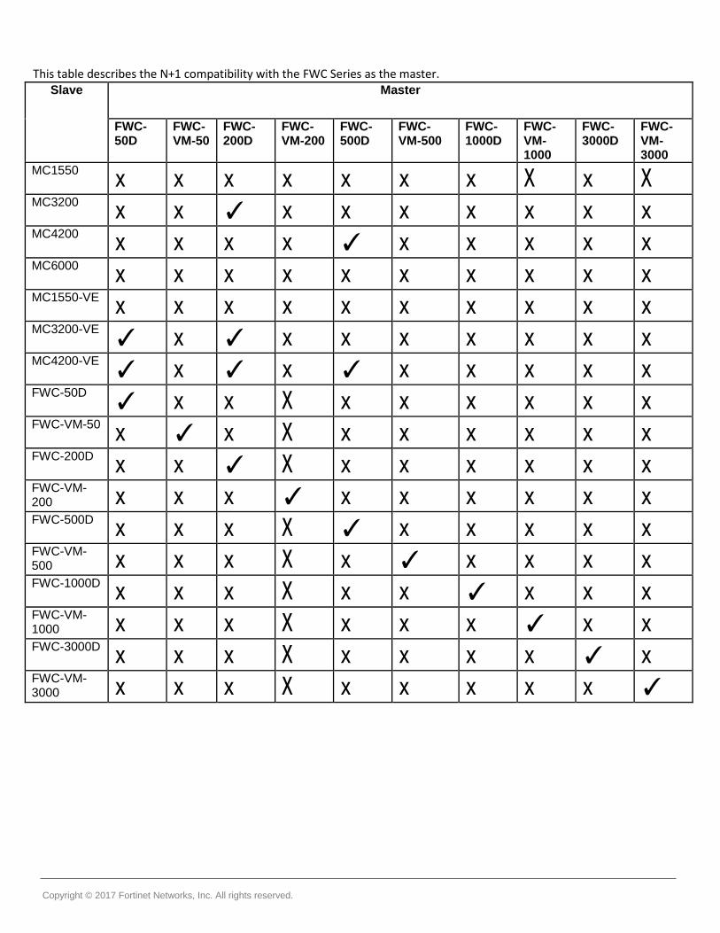
This table describes the N+1 compatibility with the FWC Series as the master. Slave
Master
FWC-50D
FWC-VM-50
FWC-200D
FWC-VM-200
FWC-500D
FWC-VM-500
FWC-1000D
FWC-VM-1000
FWC-3000D
FWC-VM-3000
MC1550 x x x x x x x X x X
MC3200 x x ✓ x x x x x x x
MC4200 x x x x ✓ x x x x x
MC6000 x x x x x x x x x x
MC1550-VE x x x x x x x x x x
MC3200-VE ✓ x ✓ x x x x x x x
MC4200-VE ✓ x ✓ x ✓ x x x x x
FWC-50D ✓ x x X x x x x x x
FWC-VM-50 x ✓ x X x x x x x x
FWC-200D x x ✓ X x x x x x x
FWC-VM-200 x x x ✓ x x x x x x
FWC-500D x x x X ✓ x x x x x
FWC-VM-500 x x x X x ✓ x x x x
FWC-1000D x x x X x x ✓ x x x
FWC-VM-1000 x x x X x x x ✓ x x
FWC-3000D x x x X x x x x ✓ x
FWC-VM-3000 x x x X x x x x x ✓

Copyright © 2017 Fortinet Networks, Inc. All rights reserved.
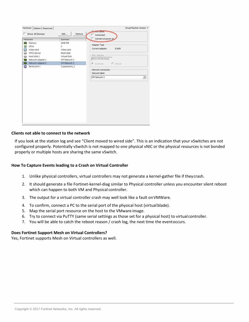
Troubleshooting Tips APs not connecting to the controller & seeing duplicate responses for pings from the controller to an outside system
The same vSwitch is being used for both vNICs, define separate vSwitches for each vNIC. Alternatively you could disable one of the vNICs in the virtual machine. You can disable the 2nd vNIC, by un-checking the Connected and Connect at Power On options.
Copyright © 2017 Fortinet Networks, Inc. All rights reserved.
Clients not able to connect to the network
If you look at the station log and see “Client moved to wired side”. This is an indication that your vSwitches are not configured properly. Potentially vSwitch is not mapped to one physical vNIC or the physical resources is not bonded properly or multiple hosts are sharing the same vSwitch.
How To Capture Events leading to a Crash on Virtual Controller
1. Unlike physical controllers, virtual controllers may not generate a kernel-gather file if they crash.
2. It should generate a file Fortinet-kernel-diag similar to Physical controller unless you encounter silent reboot which can happen to both VM and Physical controller.
3. The output for a virtual controller crash may well look like a fault on VMWare.
4. To confirm, connect a PC to the serial port of the physical host (virtual blade). 5. Map the serial port resource on the host to the VMware image. 6. Try to connect via PuTTY (same serial settings as those set for a physical host) to virtual controller. 7. You will be able to catch the reboot reason / crash log, the next time the event occurs.
Does Fortinet Support Mesh on Virtual Controllers? Yes, Fortinet supports Mesh on Virtual controllers as well.

Copyright © 2017 Fortinet Networks, Inc. All rights reserved.
Notice
ALL INFORMATION PROVIDED IN THIS DEPLOYMENT GUIDE, INCLUDING COMMENTARY, OPINION, FORTINET NETWORKS DESIGN SPECIFICATIONS, AND OTHER DOCUMENTS (TOGETHER AND SEPARATELY, “MATERIALS”) ARE BEING PROVIDED “AS IS.” FORTINET NETWORKS MAKES NO WARRANTIES, EXPRESSED, IMPLIED, STATUTORY, OR OTHERWISE WITH RESPECT TO MATERIALS, AND EXPRESSLY DISCLAIMS ALL IMPLIED WARRANTIES OF NONINFRINGEMENT, MERCHANTABILITY, AND FITNESS FOR A PARTICULAR PURPOSE.
