virtualizing splunk on nutanix - midland information systems · virtualizing splunk on nutanix 2....
TRANSCRIPT

Virtualizing Splunk onNutanix
Nutanix Reference Architecture
Version 1.3 • June 2018 • RA-2019

Virtualizing Splunk on Nutanix
Copyright | 2
Copyright
Copyright 2018 Nutanix, Inc.
Nutanix, Inc.1740 Technology Drive, Suite 150San Jose, CA 95110
All rights reserved. This product is protected by U.S. and international copyright and intellectualproperty laws.
Nutanix is a trademark of Nutanix, Inc. in the United States and/or other jurisdictions. All othermarks and names mentioned herein may be trademarks of their respective companies.

Virtualizing Splunk on Nutanix
3
Contents
1. Executive Summary................................................................................ 5
2. Introduction..............................................................................................62.1. Audience........................................................................................................................ 62.2. Purpose..........................................................................................................................6
3. Nutanix Enterprise Cloud Overview...................................................... 73.1. Nutanix Acropolis Architecture...................................................................................... 8
4. Splunk Architecture................................................................................ 94.1. Indexes Any Data from Any Source..............................................................................94.2. Forwards Data from Remote Systems.......................................................................... 94.3. Correlates Complex Events...........................................................................................94.4. Delivers Enterprise-Class Scale, Resilience, and Interoperability............................... 104.5. A Platform for Enterprise Apps................................................................................... 10
5. Splunk on Nutanix.................................................................................125.1. Why Run Splunk on Nutanix?..................................................................................... 135.2. Data Tiering and Management....................................................................................135.3. Compression................................................................................................................ 165.4. Erasure Coding............................................................................................................165.5. Disk Balancing............................................................................................................. 195.6. Data I/O Detail.............................................................................................................225.7. Deployment Options.................................................................................................... 23
6. Solution Design..................................................................................... 306.1. Design Decisions......................................................................................................... 306.2. Splunk Sizing...............................................................................................................336.3. Solution Application..................................................................................................... 376.4. Nutanix Compute and Storage....................................................................................466.5. Network........................................................................................................................46

Virtualizing Splunk on Nutanix
4
7. Validation and Benchmarking..............................................................487.1. Environment Overview.................................................................................................487.2. Test Scripts and Configurations.................................................................................. 507.3. Benchmarks................................................................................................................. 547.4. How to Interpret the Results....................................................................................... 547.5. Results......................................................................................................................... 55
8. From Bare Metal to Nutanix: A Brief Customer Case Study..............62
9. Conclusion............................................................................................. 65
Appendix......................................................................................................................... 66References.......................................................................................................................... 66About the Author.................................................................................................................66About Nutanix......................................................................................................................66
List of Figures................................................................................................................67
List of Tables................................................................................................................. 69
Virtualizing Splunk on Nutanix
1. Executive Summary | 5
1. Executive Summary
A scale-out application like Splunk demands a scale-out infrastructure like Nutanix to grow alongwith it. This document makes recommendations for the design, optimization, and scaling ofSplunk deployments on Nutanix. It shows the scalability of the Nutanix Enterprise Cloud andprovides detailed performance and configuration information on the scale-out capabilities of thecluster when used for Splunk deployments.
Our extensive testing simulated both real-world workloads and the conditions of a Splunkenvironment on Nutanix. We completed the solution and testing data with Splunk deployed onVMware vSphere and on Nutanix AHV. Both environments ran on identical Nutanix platforms.We validated testing using SplunkIT and Bonnie++.
The Bonnie++ results showed ample bandwidth, with approximately 692 MBps for sequentialwrite and approximately 680 MBps for read for a single VM per node with eight vCPUs and 8 GBof memory. Bonnie++ random seeks saw approximately 33,564 seeks per second for a singleVM per node. These numbers are significantly higher than Splunk’s recommendations, and theyscale linearly as you add new nodes to the Splunk and Nutanix environment. Adding nodesalso allows storage capacity, indexing, and search performance to scale and helps generate aconsistent end-user experience.
The Splunk on Nutanix solution provides a single high-density platform for Splunk, VM hosting,and application delivery. Whatever your company’s requirements, there is a range of Nutanixmodels to choose from.

Virtualizing Splunk on Nutanix
2. Introduction | 6
2. Introduction
2.1. AudienceThis reference architecture is intended for those designing, managing, and supportingNutanix infrastructures. Consumers of this document should already be familiar with Splunk,virtualization, and the Nutanix platform.
We have organized this document to address key items for enabling successful design,implementation, and transition to operation.
2.2. PurposeThis document covers the following subject areas:
• Overview of the Nutanix solution.
• Overview of Splunk and its use cases.
• The benefits of Splunk on Nutanix.
• Recommendations for architecting a complete Splunk solution on the Nutanix platform,including design and configuration considerations.
• Benchmarks for Splunk performance on Nutanix.
Table 1: Document Version History
VersionNumber
Published Notes
1.0 July 2015 Original publication.
1.1 July 2016 Updated platform overview.
1.2 May 2017Added consideration of multisite deployments, highavailability, customer use cases, and Splunk EnterpriseSecurity sizing.
1.3 June 2018 Updated platform overview.
Virtualizing Splunk on Nutanix
3. Nutanix Enterprise Cloud Overview | 7
3. Nutanix Enterprise Cloud Overview
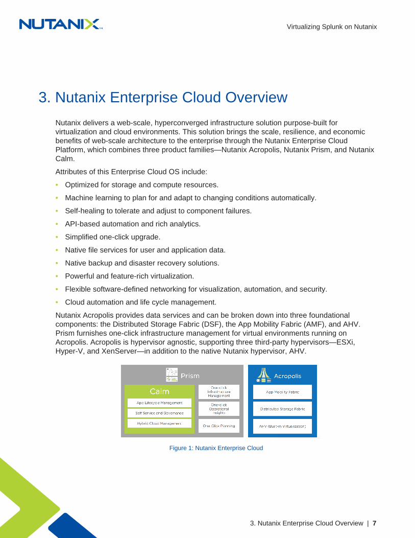
Nutanix delivers a web-scale, hyperconverged infrastructure solution purpose-built forvirtualization and cloud environments. This solution brings the scale, resilience, and economicbenefits of web-scale architecture to the enterprise through the Nutanix Enterprise CloudPlatform, which combines three product families—Nutanix Acropolis, Nutanix Prism, and NutanixCalm.
Attributes of this Enterprise Cloud OS include:
• Optimized for storage and compute resources.
• Machine learning to plan for and adapt to changing conditions automatically.
• Self-healing to tolerate and adjust to component failures.
• API-based automation and rich analytics.
• Simplified one-click upgrade.
• Native file services for user and application data.
• Native backup and disaster recovery solutions.
• Powerful and feature-rich virtualization.
• Flexible software-defined networking for visualization, automation, and security.
• Cloud automation and life cycle management.
Nutanix Acropolis provides data services and can be broken down into three foundationalcomponents: the Distributed Storage Fabric (DSF), the App Mobility Fabric (AMF), and AHV.Prism furnishes one-click infrastructure management for virtual environments running onAcropolis. Acropolis is hypervisor agnostic, supporting three third-party hypervisors—ESXi,Hyper-V, and XenServer—in addition to the native Nutanix hypervisor, AHV.
Figure 1: Nutanix Enterprise Cloud

Virtualizing Splunk on Nutanix
3. Nutanix Enterprise Cloud Overview | 8
3.1. Nutanix Acropolis ArchitectureAcropolis does not rely on traditional SAN or NAS storage or expensive storage networkinterconnects. It combines highly dense storage and server compute (CPU and RAM) into asingle platform building block. Each building block delivers a unified, scale-out, shared-nothingarchitecture with no single points of failure.
The Nutanix solution requires no SAN constructs, such as LUNs, RAID groups, or expensivestorage switches. All storage management is VM-centric, and I/O is optimized at the VM virtualdisk level. The software solution runs on nodes from a variety of manufacturers that are eitherall-flash for optimal performance, or a hybrid combination of SSD and HDD that provides acombination of performance and additional capacity. The DSF automatically tiers data across thecluster to different classes of storage devices using intelligent data placement algorithms. Forbest performance, algorithms make sure the most frequently used data is available in memory orin flash on the node local to the VM.
To learn more about the Nutanix Enterprise Cloud, please visit the Nutanix Bible andNutanix.com.
Virtualizing Splunk on Nutanix
4. Splunk Architecture | 9
4. Splunk Architecture
4.1. Indexes Any Data from Any SourceSplunk Enterprise collects and indexes machine-generated data from virtually any source,format, or location in real time. This capability includes data streaming from packaged andcustom applications, app servers, web servers, databases, networks, VMs, telecom equipment,operating systems, sensors, and much more. There’s no requirement for Splunk Enterprise to“understand” the data up front; it immediately starts collecting and indexing your data so you canstart searching and analyzing.
You can find additional product information online.
4.2. Forwards Data from Remote SystemsSplunk forwarders are useful in situations where the data you need isn’t visible over the network.They deliver reliable, secure, real-time data collection for up to tens of thousands of sources.Splunk forwarders can monitor local application logfiles, capture status command output on aschedule, grab performance metrics from virtual or nonvirtual sources, or watch the file systemfor configuration, permissions, and attribute changes. They are also lightweight, and you candeploy them quickly at no additional cost.
4.3. Correlates Complex EventsSplunk Enterprise enables you to correlate complex events spanning many diverse data sourcesacross your environment. Types of correlations include:
• Time-based correlations, which identify relationships based on time, proximity, or distance.
• Transaction-based correlations, which track a series of related events as a single transactionto measure duration, status, or other metrics.
• Subsearches, which take the results of one search and use them in another.
• Lookups, which correlate data with external data sources outside Splunk.
• Joins, which support SQL-like inner and outer joins.

Virtualizing Splunk on Nutanix
4. Splunk Architecture | 10
4.4. Delivers Enterprise-Class Scale, Resilience, and InteroperabilitySplunk Enterprise scales to collect and index dozens of terabytes of data per day. Because theinsights drawn from your data are mission-critical, Splunk software’s index replication technologyprovides the availability you need, even as you scale out your distributed computing environment.Automatic load balancing optimizes workloads and response times and provides built-in failoversupport. Out-of-the-box reporting and analytics capabilities deliver rapid insights from your data.
Splunk DB Connect delivers reliable, scalable, real-time integration between Splunk andtraditional relational databases. Splunk Hadoop Connect provides bidirectional integration tomove data easily and reliably between Splunk Enterprise and Hadoop.
4.5. A Platform for Enterprise AppsDeveloper teams can find a host of ways to leverage Splunk Enterprise. You can debug andtroubleshoot applications during development and test cycles, or integrate data from SplunkEnterprise into custom applications. With API versioning, you can output data from any APIendpoint in JSON and ensure custom Splunk development over time. Splunk Enterprise shipswith the JavaScript SDK as well as additional downloadable SDKs for Java, Python, and PHP,making it easy to customize and extend.
Deployment Scenario: Single Instance
In single-machine deployments, one instance of Splunk handles the entire end-to-end process,from data input, through indexing, to search. A single-machine deployment can be useful fortesting and evaluation purposes and might serve the needs of department-sized environments.For larger environments, however, where data originates on many machines and where manyusers need to search the data, administrators can distribute functionality across multiple Splunkinstances.
In a typical midsize deployment, for example, you can deploy lightweight versions of Splunk,called forwarders, on the machines where the data originates. The forwarders consume datalocally, then advance the data across the network to another Splunk component, called theindexer. The indexer does the heavy lifting—it indexes the data and runs searches—and shouldreside on a machine by itself. The forwarders, on the other hand, can easily coexist on themachines generating the data, because the data-consuming function has minimal impact onmachine performance.
As you scale up, you can add more forwarders and indexers. A large deployment may havehundreds of forwarders sending data to a number of indexers. You can use load balancing onthe forwarders, so that they distribute their data across some or all of the indexers. Not only doesload balancing help with scaling, it also provides a failover capability if one of the indexers goes

Virtualizing Splunk on Nutanix
4. Splunk Architecture | 11
down, because the forwarders automatically switch to sending their data to the indexers thatremain.
Deployment Scenario: Search Head Cluster
A search head cluster consists of a group of search heads that share configurations, jobscheduling, and search artifacts. The search heads are known as the cluster members.
One cluster member has the role of captain, which means that it coordinates job schedulingand replication activities among all the members. It also serves as a search head like any othermember, running search jobs, serving results, and so on. Over time, the role of captain can shiftamong the cluster members.
For more information, see the Splunk Enterprise Distributed Deployment Manual.
Deployment Scenario: Multisite Indexer Cluster
A multisite indexer cluster is essentially an indexer cluster that spans multiple physical sites—datacenters, for example. Each site has its own set of peer nodes and search heads. Each sitealso obeys site-specific replication and search factor rules, thereby providing multisite awarenessand delivering improved disaster recovery and search head affinity.
The main differences between multisite clusters and single-site deployments are that, in amultiple-site configuration:
• Each node belongs to an assigned site.
• Bucket copy replication is site-aware.
• Search heads distribute their searches across only local peers whenever possible.
Bear in mind that you can migrate an indexer cluster from single-site to multisite. However, aftersuch a migration, the cluster holds both single-site and multisite buckets. It maintains thesebuckets separately, following these rules:
• Single-site buckets (those existing at the time of migration) continue to respect their single-sitereplication and search factors. You cannot convert them to multisite.
• Multisite buckets (those created after migration) follow the multisite replication and searchfactor policies.
If there is a chance that you may wish to deploy across multiple sites in the future, werecommend configuring the indexer cluster to be site-aware from the outset. Consult your localSplunk representative regarding such installations. For further details regarding multisite indexerclusters, please refer to Splunk’s multisite indexer cluster deployment overview.

Virtualizing Splunk on Nutanix
5. Splunk on Nutanix | 12
5. Splunk on Nutanix
The Nutanix platform operates and scales Splunk in conjunction with other hosted services,providing a single scalable infrastructure for all deployments. Existing sources can send machinedata to the Splunk environment on Nutanix over the network. The figure below shows a high-levelview of the Splunk on Nutanix solution.
Figure 2: Splunk + Nutanix High-Level Architecture

Virtualizing Splunk on Nutanix
5. Splunk on Nutanix | 13
5.1. Why Run Splunk on Nutanix?Nutanix enables you to run multiple workloads on the same scalable converged infrastructure.
• Modular incremental scale
With the Nutanix solution, you can start small and scale. A single Nutanix block (up to fournodes) provides from 20 TB to 240 TB or more of storage and up to 176 cores in a compactfootprint. Given the modularity of the solution, you can scale one node at a time, giving youthe ability to accurately match supply with demand and minimize the upfront capex.
• High performance
The Nutanix solution provides 250,000 or more random read IOPS and up to 5 GB per secondof sequential throughput in a compact 2RU (rack unit) cluster. Performance scales linearly asnew nodes are added to the cluster.
• Data efficiency
The Nutanix solution is truly VM-centric for all compression policies. Unlike traditionalsolutions that perform compression mainly at the LUN level, the Nutanix solution provides allof these transformations at the VM and file levels, greatly increasing efficiency and simplicity.These capabilities ensure the highest possible compression and decompression performanceon a subblock level. By allowing for both inline and post-process compression, the Nutanixsolution breaks the bounds set by traditional data efficiency solutions.
• High-density architecture
Nutanix uses an advanced server architecture in which eight Intel CPUs (up to 176 cores) andup to 2 TB of memory are integrated into a single 2RU appliance. Coupled with data archivingand compression, Nutanix can reduce hardware footprint by as much as 400 percent.
• Effective information life-cycle management
The Nutanix architecture supports local disks attached to the CVM (SSD, HDD) as well asremote (NAS) and cloud-based source targets. The tiering logic is fully extensible, allowingyou to add and extend new tiers dynamically.
5.2. Data Tiering and ManagementSplunk has a built-in mechanism to age index data automatically as it grows stale. An indexconsists of multiple directories or “buckets.” These buckets function as data storage mechanismsand progress (or “roll”) through various stages as the data ages.
Splunk writes all newly indexed data to a searchable hot bucket and, after the bucket reaches aparticular size, rolls that data to a warm bucket. Splunk does not actively write to warm buckets;

Virtualizing Splunk on Nutanix
5. Splunk on Nutanix | 14
warm buckets do, however, remain searchable. As buckets roll into the warm stage, the oldestwarm buckets roll to the cold stage. After a set period of time, the cold buckets roll to frozen,where they are either archived or deleted.
The DSF has a built-in information life-cycle management (ILM) process that complementsSplunk’s temporal bucket mechanism. The figure below shows the DSF I/O path and howfingerprinting and the content cache are integrated.
Figure 3: DSF I/O Path, Fingerprinting, and the Content Cache
Just as Splunk rolls data from hot, to warm, and then to cold and frozen tiers, Nutanix ILMautomatically detects that data is cooling down and then migrates that data from the SSD tothe higher-capacity HDD tier to free SSD space for new hot data. You also have the option
Virtualizing Splunk on Nutanix
5. Splunk on Nutanix | 15
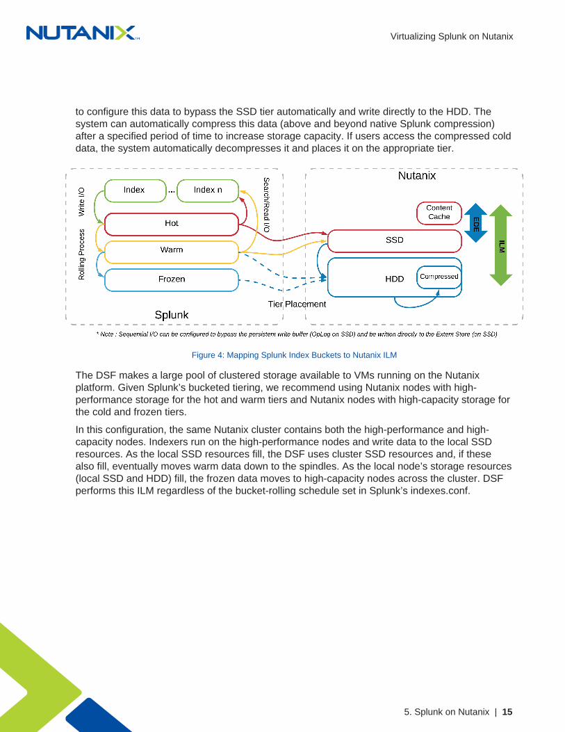
to configure this data to bypass the SSD tier automatically and write directly to the HDD. Thesystem can automatically compress this data (above and beyond native Splunk compression)after a specified period of time to increase storage capacity. If users access the compressed colddata, the system automatically decompresses it and places it on the appropriate tier.
Figure 4: Mapping Splunk Index Buckets to Nutanix ILM
The DSF makes a large pool of clustered storage available to VMs running on the Nutanixplatform. Given Splunk’s bucketed tiering, we recommend using Nutanix nodes with high-performance storage for the hot and warm tiers and Nutanix nodes with high-capacity storage forthe cold and frozen tiers.
In this configuration, the same Nutanix cluster contains both the high-performance and high-capacity nodes. Indexers run on the high-performance nodes and write data to the local SSDresources. As the local SSD resources fill, the DSF uses cluster SSD resources and, if thesealso fill, eventually moves warm data down to the spindles. As the local node’s storage resources(local SSD and HDD) fill, the frozen data moves to high-capacity nodes across the cluster. DSFperforms this ILM regardless of the bucket-rolling schedule set in Splunk’s indexes.conf.

Virtualizing Splunk on Nutanix
5. Splunk on Nutanix | 16
Figure 5: Splunk ILM Series Mapping
Note: The Splunk VM only needs a single mount point configured for all buckets.
This arrangement simplifies configuration and management, as the Nutanix platformautomatically handles bucket placement without multiple storage platforms or clusters.
5.3. CompressionNutanix recommends post-process compression with at least a 48-hour delay for Splunk onNutanix deployments. When Splunk ingests data into the indexers, it uses transient files to collectdata into 128 KB slices, then coalesces and compresses those slices into the final index file.Because the transient files only exist for as long as it takes to collect 128 KB of data ingest, youdon’t need to spend Nutanix CPU resources on compressing them inline.
Nutanix uses a two-phase post-process compression methodology. The initial compression pass(LZ4) works on data that has been inactive for greater than one day, then a further compressionscheme (LZ4HC) transforms data that has been cold for three days. When compared to earlieralgorithms such as Snappy, the LZ4 compression family offers an improved tradeoff betweencompression and decompression speeds versus CPU utilization.
5.4. Erasure CodingThe Nutanix platform relies on a replication factor for data protection and availability. This methodprovides the highest degree of availability because it does not require the system to recomputedata upon failure or to read from more than one storage location. However, this feature requiresfull copies and thus occupies additional storage resources. Nutanix strikes a balance between

Virtualizing Splunk on Nutanix
5. Splunk on Nutanix | 17
providing availability and reducing required storage by transforming data using erasure coding(EC-X).
Similar to the concept of RAID (levels 4, 5, 6, and so on), EC-X encodes a strip of data blocks ondifferent nodes and calculates parity. In the event of a host or disk failure, the system can use theparity to decode any missing data blocks. In the DSF, the data block is an extent group, and eachdata block must be on a different node and belong to a different vDisk.
You can configure the number of data and parity blocks based on how many failures you needto be able to tolerate. In most cases, we can think of the configuration as the <number of datablocks> / <number of parity blocks>.
For example, replication factor 2 availability (N + 1) could consist of three or four data blocksand one parity block in a strip (3/1 or 4/1). Replication factor 3 availability (N + 2) could consist ofthree or four data blocks and two parity blocks in a strip (3/2 or 4/2).
We can calculate the expected overhead as <# parity blocks> / <# parity blocks + # data blocks>.For example, a 4/1 strip has 20 percent overhead, or 1.25x, compared to the 2x of replicationfactor 2.
EC-X is a post-process framework that does not affect the traditional write I/O path. Theencoding uses the Curator MapReduce framework for task distribution.
The following figure depicts a normal environment using replication factors.
Figure 6: Data Protection: Traditional Replication Factors
In this scenario, we have a mix of both replication factor 2 and replication factor 3 data, withprimary copies stored locally and replicas distributed to other nodes throughout the cluster.

Virtualizing Splunk on Nutanix
5. Splunk on Nutanix | 18
When a Curator full scan runs, it finds eligible extent groups available for EC-X and distributesand throttles the encoding tasks via Chronos.
The figure below shows an example 4/1 and 3/2 strip.
Figure 7: Erasure-Coded Strip
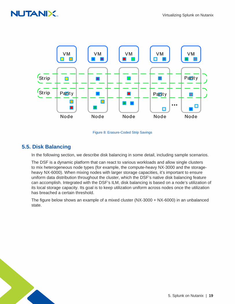
Once EC-X has successfully calculated the strips and parity, the system removes the replicaextent groups. The figure below shows the storage savings in the environment after running EC-X.
Virtualizing Splunk on Nutanix
5. Splunk on Nutanix | 19
Figure 8: Erasure-Coded Strip Savings
5.5. Disk BalancingIn the following section, we describe disk balancing in some detail, including sample scenarios.
The DSF is a dynamic platform that can react to various workloads and allow single clustersto mix heterogeneous node types (for example, the compute-heavy NX-3000 and the storage-heavy NX-6000). When mixing nodes with larger storage capacities, it’s important to ensureuniform data distribution throughout the cluster, which the DSF’s native disk balancing featurecan accomplish. Integrated with the DSF’s ILM, disk balancing is based on a node’s utilization ofits local storage capacity. Its goal is to keep utilization uniform across nodes once the utilizationhas breached a certain threshold.
The figure below shows an example of a mixed cluster (NX-3000 + NX-6000) in an unbalancedstate.

Virtualizing Splunk on Nutanix
5. Splunk on Nutanix | 20
Figure 9: Disk Balancing: Unbalanced
Disk balancing uses the DSF Curator framework and runs both as a scheduled process andwhen a node has breached a set threshold (in other words, when local node capacity utilizationis greater than n percent). When the data is not balanced, Curator determines which data needsto be moved and distributes the movement tasks to nodes in the cluster. When a cluster’snode types are homogeneous (for example, all NX-3000s), utilization should be fairly uniform.However, if there are VMs writing much more data than others, the per-node capacity utilizationcan become skewed. In this case, disk balancing runs, moving the coldest data on the overusednode to other nodes in the cluster. When the node types are heterogeneous (for example,NX-3000 + NX-6000 or NX-6035) or when a node is used in a storage-only mode (not runningany VMs), you’re more likely to need to move data.
The figure below shows an example of a mixed cluster in a balanced state after running diskbalancing.

Virtualizing Splunk on Nutanix
5. Splunk on Nutanix | 21
Figure 10: Disk Balancing: Balanced
Users can also run some nodes in a storage-only state, so only the CVM runs on nodes whoseprimary purpose is bulk storage capacity. In this case, the CVM can access the full node’smemory to provide a much larger read cache. The figure below shows an example of diskbalancing moving data to a storage-only node in a mixed cluster from the active VM nodes.
Figure 11: Disk Balancing: Storage-Only Node

Virtualizing Splunk on Nutanix
5. Splunk on Nutanix | 22
5.6. Data I/O DetailThe figure below represents the high-level I/O path for VMs and Splunk instances running onNutanix. The DSF handles all I/O operations, which occur on the local node to provide the fastestpossible I/O performance. Machine data writes to the Splunk indexer locally for all VMs on thesame hypervisor node and over 10 GbE for VMs and sources hosted remotely or on anothernode.
Figure 12: High-Level Data I/O Path
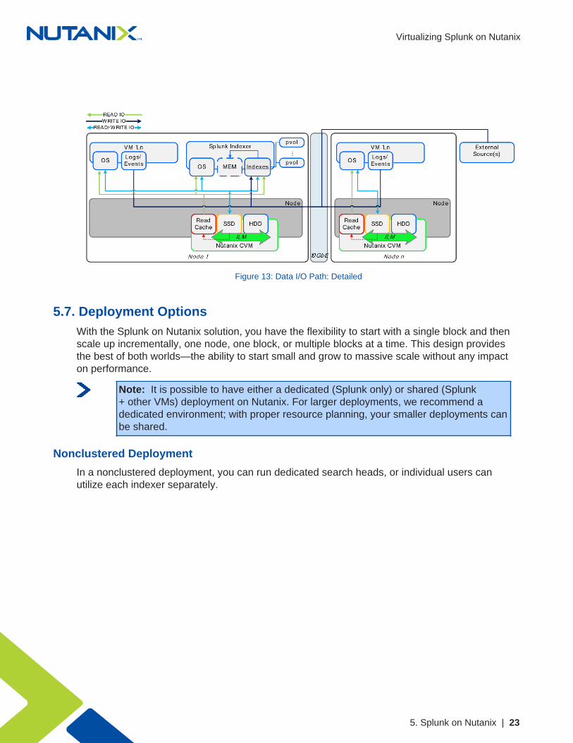
The figure below describes the detailed I/O path for VMs and Splunk instances running onNutanix. All write I/O—including data input to the Splunk indexer—occurs on the local node’sSSD tier to provide the highest possible performance. Read requests for the Splunk indexesoccur locally and are served from the high-performance in-memory read cache (if cached), orfrom the SSD or HDD tier, depending on placement. Each node also saves frequently accessedlocal data in the read cache (for example, VM data or Splunk indexes). Nutanix ILM constantlymonitors data and I/O patterns to choose the appropriate tier placement.
Virtualizing Splunk on Nutanix
5. Splunk on Nutanix | 23
Figure 13: Data I/O Path: Detailed
5.7. Deployment OptionsWith the Splunk on Nutanix solution, you have the flexibility to start with a single block and thenscale up incrementally, one node, one block, or multiple blocks at a time. This design providesthe best of both worlds—the ability to start small and grow to massive scale without any impacton performance.
Note: It is possible to have either a dedicated (Splunk only) or shared (Splunk+ other VMs) deployment on Nutanix. For larger deployments, we recommend adedicated environment; with proper resource planning, your smaller deployments canbe shared.
Nonclustered Deployment
In a nonclustered deployment, you can run dedicated search heads, or individual users canutilize each indexer separately.

Virtualizing Splunk on Nutanix
5. Splunk on Nutanix | 24
Figure 14: Nonclustered Deployment
Search Head Cluster Deployment
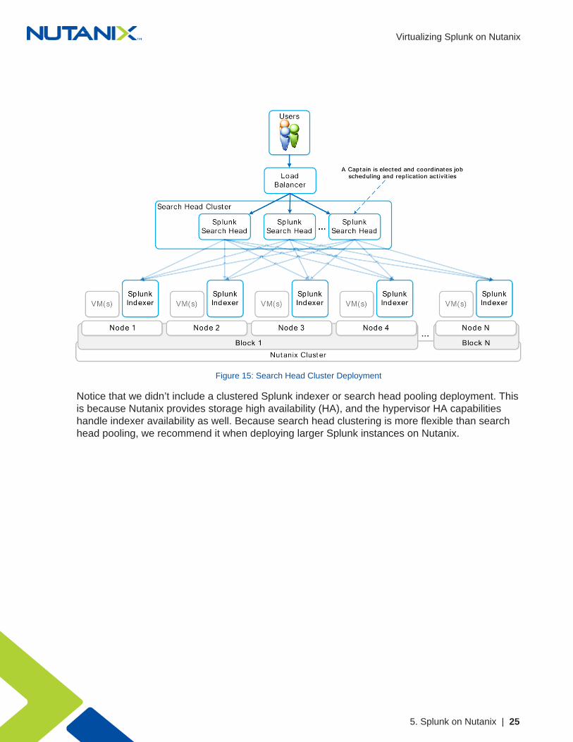
A search head cluster deployment brings together multiple Splunk search heads to form adistributed search platform. You can then use a load balancer to distribute the user load acrossthe search heads.
Virtualizing Splunk on Nutanix
5. Splunk on Nutanix | 25
Figure 15: Search Head Cluster Deployment
Notice that we didn’t include a clustered Splunk indexer or search head pooling deployment. Thisis because Nutanix provides storage high availability (HA), and the hypervisor HA capabilitieshandle indexer availability as well. Because search head clustering is more flexible than searchhead pooling, we recommend it when deploying larger Splunk instances on Nutanix.

Virtualizing Splunk on Nutanix
5. Splunk on Nutanix | 26
Multiple Index Cluster Architecture
Figure 16: Multiple Indexer Cluster Architecture Across Two Sites
DSF Provides Redundancy Across Multisite Indexer Clusters
Multisite Splunk configurations running on the Nutanix Enterprise Cloud set both the sitereplication and site search factors to maintain a single copy of an index bucket at the siteoriginating the data (in other words, the site that is receiving external data). The alternatesite maintains an additional index copy. As the Nutanix platform always maintains block-levelredundancy, both the originating and remote site buckets replicate per the overall Nutanixcluster-level redundancy factor, which is 2 by default.
The diagram below shows the server.conf settings you need in order to configure multisiteindexing on the Nutanix platform. Search factor, sites, and so on require additional settings.Please refer to the Splunk documentation for the most up-to-date information.

Virtualizing Splunk on Nutanix
5. Splunk on Nutanix | 27
Figure 17: Splunk Site Replication Factor Changes on Nutanix
Nutanix High Availability
The following diagrams cover various common failure scenarios. In them, we demonstrate howthe Acropolis management software protects against outages and show the potential benefits theNutanix self-healing mechanisms can bring to Splunk cluster components.
Figure 18: Nutanix Cluster Hosting Splunk VMs

Virtualizing Splunk on Nutanix
5. Splunk on Nutanix | 28
In the figure above, we show the Nutanix cluster in a steady state, in which both platform- andapplication-level components are working as expected. Subsequently, if the CVM on any hostreboots or fails, the autopath functionality redirects the application VM’s I/O to an alternateCVM. With this redirection, a Splunk indexer or search head, for example, doesn’t need tomigrate to another hypervisor host. Hence, there’s no need to take any remedial action (suchas a postmigration index rebalance or maintenance of site-specific bucket replication levels) atthe Splunk level. Once the CVM outage ends (for example, a reboot completes after softwareupgrade), the I/O path returns to the local CVM. For more details on CVM failure handling, referto the Nutanix online documentation.
Figure 19: Nutanix Autopath Redirects I/O on CVM Failure
During a host failure, Nutanix HA can live migrate Splunk application VMs to an alternate host.In a multisite Splunk deployment, the cluster master exists on one of the sites. In order to protectthis important component, Nutanix enables live migration to preserve cluster master uptime.The same protection is available for both indexer and search head components. When a Splunkindexer peer node fails, an administrator can decide between:
1. Allowing live migration and preserving data locality via the Nutanix distributed processes.2. Letting the Splunk application handle what Splunk calls bucket fixup. In this operation, when
Splunk loses an indexer, the system creates additional index bucket copies across theremaining nodes, making additional indexes searchable.
For more details on handling host failure, refer to the Nutanix online documentation and Splunkcomponent recovery in multisite indexer scenarios.

Virtualizing Splunk on Nutanix
5. Splunk on Nutanix | 29
Figure 20: Nutanix HA Live Migrates Application VMs on Cluster Host Failure

Virtualizing Splunk on Nutanix
6. Solution Design | 30
6. Solution Design
6.1. Design DecisionsThe following table covers design decisions and rationale for Splunk on the Nutanix EnterpriseCloud.
Note: If this is a Splunk Enterprise Security deployment, please see the AdditionalSizing Considerations When Running Splunk Enterprise Security section below.
Table 2: General Design Decisions
Item Detail Rationale
General
Minimum Size3 Nutanix nodes (3 hypervisorhosts)
Minimum size requirement
Scale Approach Incremental modular scaleAllow for growth from PoC tomassive scale
Scale Unit Node(s), block(s), or pod(s)Granular scale to preciselymeet the capacity demands
Infrastructure Services
Small deployments: sharedcluster
Large deployments: dedicatedcluster
(Node A from 3 blocks or a1350)
Dedicated infrastructurecluster for larger deployments(best practice)
Nutanix

Virtualizing Splunk on Nutanix
6. Solution Design | 31
Item Detail Rationale
Cluster Size
< 32 nodes: 1 cluster
> 32 nodes: 2 clusters scaledup to 48 nodes each
> 96 nodes: 1 additionalcluster every 48 nodes
Isolated fault domains
Keeping single hop betweennodes
Storage Pool 1 storage pool per clusterStandard practice
ILM handles tiering
Container
1 container for VMs and data
Replication factor: 2
Features: compression + EC-X
Standard practice
Compression for index files
Features and EnhancementsIncrease CVM memory to 32GB
Best practice
Splunk Platform
Distributed Deployment No VM HA for availability
Search Head Pooling NoSearch head clustering usedinstead
Search Head Clustering Yes, for larger deployments
Miscellaneous
LVM Stripe Size 32 KB or 64 KB Best performance
Disks in LVM Volume 6 Best performance
The Nutanix solution supports deployments on multiple hypervisors. We’ve outlined anyhypervisor-specific design decisions in the table below.
Table 3: Hypervisor Specific Decisions
Item Detail Rationale
AHV

Virtualizing Splunk on Nutanix
6. Solution Design | 32
Item Detail Rationale
Cluster SizeSame as Nutanix cluster size
(minimum of 3 hosts)Isolated fault domains
Infrastructure Services Hosting N/A Built into Nutanix platform
Datastore N/A iSCSI disks utilized
vSphere
Cluster SizeUp to 48 hypervisor hosts(minimum of 3 hosts)
Isolated fault domains
Clusters per vCenter Up to 4x 16 host clusters Task parallelization
Infrastructure Services Hosting
Small deployments: sharedcluster
Large deployments: dedicatedcluster
Dedicated infrastructurecluster for larger deployments(best practice)
Datastore1 Nutanix NFS datastore perpod for VMs and data
Nutanix handles I/Odistribution and localization
Below we’ve determined Splunk component VM sizes based on their reference hardware andinternal testing.
Table 4: Splunk Indexer VM Sizing
VM CPU ResourcesMemoryResources
Disk Resources Capability
Small 4 vCPUs* 8 GB+OS: 1x n GB
DATA: 6x n GB
Up toapproximately150 GB per dayindexing
Medium 8 vCPUs* 16 GB+OS: 1x n GB
DATA: 6x n TB
Up toapproximately200 GB per dayindexing

Virtualizing Splunk on Nutanix
6. Solution Design | 33
Large or SplunkES
16 vCPUs* 32 GB+OS: 1x n GB
DATA: 6x n TB
Up toapproximately300 GB per dayindexing; SplunkES indexerssupport 100 GBper day ingest
* If you see the CPU pegged at 100 percent, you can increase the number of vCPUs. KeepvCPU count within a NUMA boundary and make sure that the number of vCPUs is fewer thanthe total number of cores minus the cores used for the Nutanix CVM.
The table below offers Splunk search head VM sizing recommendations for medium and largedeployments. In a small configuration, you do not need a separate search head.
Table 5: Splunk Search Head VM Sizing
VM CPU ResourcesMemoryResources
Disk Resources Capability
Medium 8 vCPUs 16 GB+OS: 1x n GB
DATA: N/A
Up to 16 users per750 GB–1 TB ofdaily index data
Large or Splunk ES 16 vCPUs 32 GB+OS: 1x n GB
DATA: N/A
Up to 24 users per750 GB–1 TB ofdaily index data
Note: Splunk suggests a maximum of eight indexers per search head. Search headclustering requires a minimum of three search heads. In our design, we used themedium-sized search heads.
6.2. Splunk SizingThe following section covers the Splunk sizing and considerations for running Splunk on Nutanix.We assume a minimum of one Splunk indexer per Nutanix node.
Note: It is always a good practice to add a buffer for contingency and growth.

Virtualizing Splunk on Nutanix
6. Solution Design | 34
Indexer Sizing
Step 1a: Calculate the Estimated Required Hot and Warm Storage
• Required hot and warm storage = (daily average indexing rate in GB x hot and warm retentionpolicy in days) / 2
Note: Splunk assumes a 50 percent compression ratio.
For example, if there are 500 GB of data indexed daily and hot and warm data needs to be keptfor a minimum of two months:
• Required hot and warm storage = (500 GB per day x 60 days) / 2 = 15,000 GB = 15 TB
Step 1b: Calculate the Estimated Required Cold and Frozen Storage
• Required cold and frozen storage = ((daily average indexing rate in GB x cold and frozenretention policy in days) / 2) – hot and warm storage
Note: Splunk assumes a 50 percent compression ratio.
For example, if there are 500 GB of data indexed daily and 15 TB of hot and warm data, and coldand frozen data is kept for one year:
• Required cold and frozen storage = ((500 GB per day x 365 days) / 2) – 15,000 GB = 76,250GB = ~76 TB
Step 1c: Calculate the Estimated Required Total Storage
• Required total storage = required hot and warm storage + required cold and frozen storage
For example, if there are 15 TB of required hot and warm data and 76 TB of required cold andfrozen data:
• Required total storage = 15 TB + 76 TB = 91 TB
Step 2a: Calculate the Total Required Number of Hot and Warm Nutanix Nodes by Storage Capacity
• Total number of Nutanix nodes for hot and warm by storage capacity = (required hot andwarm storage) / (storage per hot and warm node / Nutanix data protection overhead)
For example, if there are 15 TB of required hot and warm storage, the Nutanix data protectionoverhead is two (assuming replication factor 2 with no EC-X or compression savings), and thereare 8 TB of raw storage per hot and warm node:
• Number of Nutanix nodes for hot and warm by storage capacity = ROUNDUP (15 TB / (8 TB /2)) = 4 nodes

Virtualizing Splunk on Nutanix
6. Solution Design | 35
If we take the same inputs while leveraging EC-X, the result is an effective data protectionoverhead of 1.2 (EC 4/1 strip).
• Number of Nutanix nodes for hot and warm by storage capacity = ROUNDUP (15 TB / (8 TB /1.2)) = 3 nodes
Step 2b: Calculate the Total Required Number of Cold and Frozen Nutanix Nodes by Storage Capacity
• Total number of Nutanix nodes for cold and frozen by storage capacity = (required cold andfrozen storage) / (storage per cold and frozen node / Nutanix data protection overhead)
If there are 76 TB of required cold and frozen storage, the Nutanix data protection overhead istwo (assuming replication factor 2 with no EC-X or compression savings), and there are 16 TB ofraw storage per cold and frozen node:
• Number of Nutanix nodes for cold and frozen by storage capacity = ROUNDUP (76 TB / (16TB / 2)) = 10 nodes
If we take the same inputs while using EC-X, the result is an effective data protection overhead of1.2 (EC 4/1 strip).
• Number of Nutanix nodes for cold and frozen by storage capacity = ROUNDUP (76 TB / (16TB / 1.2)) = 6 nodes
Step 2c: Calculate the Total Required Number of Nutanix Nodes by Storage Capacity
• Total number of Nutanix nodes by storage capacity = total number of Nutanix nodes for hotand warm by storage capacity + total number of Nutanix nodes for cold and frozen by storagecapacity
Taking the outputs from above and assuming we’re using EC-X and compression, we have threenodes for hot and warm data and six nodes for cold and frozen data:
• Total number of Nutanix nodes by storage capacity = 3 nodes + 6 nodes = 9 nodes
Step 3: Calculate the Total Required Number of Nutanix Nodes for Hot and Warm Data by IndexerCapability
• Total number of Nutanix nodes for hot and warm data by indexer capability = daily averageindexing rate in GB / daily indexer ingest capability
For example, if there are 500 GB of data indexed daily and each indexer is capable of handling150 GB of data ingest:
• Number of Nutanix nodes for hot and warm data by indexer capability = ROUNDUP (500 GB /150 GB) = 4 nodes
Virtualizing Splunk on Nutanix
6. Solution Design | 36
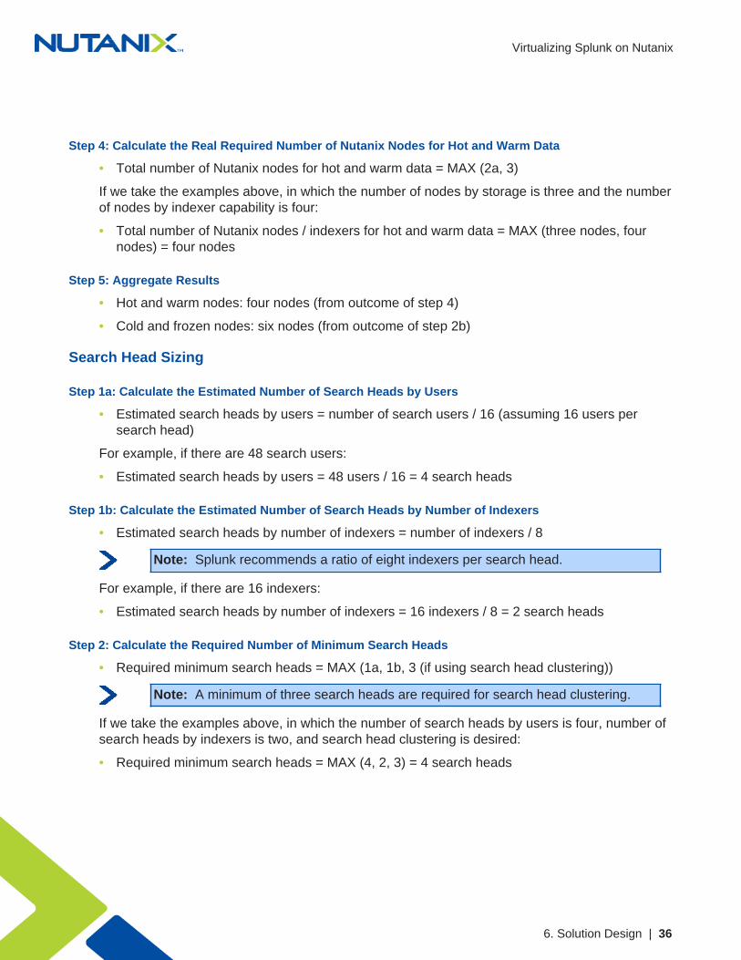
Step 4: Calculate the Real Required Number of Nutanix Nodes for Hot and Warm Data
• Total number of Nutanix nodes for hot and warm data = MAX (2a, 3)
If we take the examples above, in which the number of nodes by storage is three and the numberof nodes by indexer capability is four:
• Total number of Nutanix nodes / indexers for hot and warm data = MAX (three nodes, fournodes) = four nodes
Step 5: Aggregate Results
• Hot and warm nodes: four nodes (from outcome of step 4)
• Cold and frozen nodes: six nodes (from outcome of step 2b)
Search Head Sizing
Step 1a: Calculate the Estimated Number of Search Heads by Users
• Estimated search heads by users = number of search users / 16 (assuming 16 users persearch head)
For example, if there are 48 search users:
• Estimated search heads by users = 48 users / 16 = 4 search heads
Step 1b: Calculate the Estimated Number of Search Heads by Number of Indexers
• Estimated search heads by number of indexers = number of indexers / 8
Note: Splunk recommends a ratio of eight indexers per search head.
For example, if there are 16 indexers:
• Estimated search heads by number of indexers = 16 indexers / 8 = 2 search heads
Step 2: Calculate the Required Number of Minimum Search Heads
• Required minimum search heads = MAX (1a, 1b, 3 (if using search head clustering))
Note: A minimum of three search heads are required for search head clustering.
If we take the examples above, in which the number of search heads by users is four, number ofsearch heads by indexers is two, and search head clustering is desired:
• Required minimum search heads = MAX (4, 2, 3) = 4 search heads

Virtualizing Splunk on Nutanix
6. Solution Design | 37
6.3. Solution ApplicationYou can use the above capabilities, which are based on the various Splunk component sizes,to determine the quantity and size of the required components. For example, you can calculatethe number of indexers by taking the total amount of daily index data divided by the indexingcapability per VM size.
Small Sample Scenario
The following table contains the small sample scenario inputs.
Table 6: Small Sample Scenario Inputs
Item Detail Rationale
Indexing Inputs
Total Index DataUp to 150 GB perday
Sample size
Data Days in Hot andWarm Buckets
30 Sample input
Data Days in Cold andFrozen Buckets
30 Sample input
Min. # of Hot and WarmIndexers
1 small or 1medium
Based on daily indexing and hot and warmbucket storage
Min. # of Cold and FrozenNodes and Indexers
N/ABased on daily indexing and cold and frozenbucket storage
Search Inputs
Search Users Up to 16 Sample size
# of Search Heads N/A N/A at this scale
The table below contains the small sample scenario platform details and features.
Virtualizing Splunk on Nutanix
6. Solution Design | 38
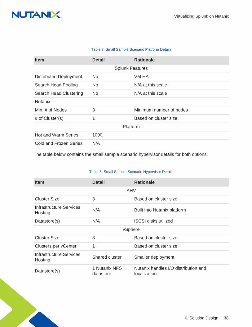
Table 7: Small Sample Scenario Platform Details
Item Detail Rationale
Splunk Features
Distributed Deployment No VM HA
Search Head Pooling No N/A at this scale
Search Head Clustering No N/A at this scale
Nutanix
Min. # of Nodes 3 Minimum number of nodes
# of Cluster(s) 1 Based on cluster size
Platform
Hot and Warm Series 1000
Cold and Frozen Series N/A
The table below contains the small sample scenario hypervisor details for both options.
Table 8: Small Sample Scenario Hypervisor Details
Item Detail Rationale
AHV
Cluster Size 3 Based on cluster size
Infrastructure ServicesHosting
N/A Built into Nutanix platform
Datastore(s) N/A iSCSI disks utilized
vSphere
Cluster Size 3 Based on cluster size
Clusters per vCenter 1 Based on cluster size
Infrastructure ServicesHosting
Shared cluster Smaller deployment
Datastore(s)1 Nutanix NFSdatastore
Nutanix handles I/O distribution andlocalization

Virtualizing Splunk on Nutanix
6. Solution Design | 39
Medium Sample Scenario
The table below contains the medium sample scenario inputs.
Table 9: Medium Sample Scenario Inputs
Item Detail Rationale
Indexing Inputs
Total Index DataUp to 500 GB perday
Sample size
Data Days in Hot andWarm Buckets
60 Sample input
Data Days in Cold andFrozen Buckets
365 Sample input
Min. # of Hot and WarmIndexers
4 mediumBased on daily indexing and hot and warmbucket storage
Min. # of Cold and FrozenNodes and Indexers
10 mediumBased on daily indexing and cold and frozenbucket storage
Search Inputs
Search Users Up to 24 Sample size
# of Search Heads 3 Minimum for search head clustering
The table below contains the medium sample scenario platform details and features.
Table 10: Medium Sample Scenario Platform Details
Item Detail Rationale
Splunk Features
Distributed Deployment No VM HA
Search Head Pooling No Not recommended
Search Head Clustering Yes Preferred approach
Nutanix

Virtualizing Splunk on Nutanix
6. Solution Design | 40
Item Detail Rationale
Min. # of Nodes 17 Minimum number of nodes
# of Cluster(s) 1 Isolated fault domains
Platform
Hot and Warm Series 3000, 8000
Cold and Frozen Series 6000
The table below contains the medium sample scenario hypervisor details for both options.
Table 11: Medium Sample Scenario Hypervisor Details
Item Detail Rationale
AHV
Cluster Size 17 Based on cluster size
Infrastructure ServicesHosting
N/A Built into Nutanix platform
Datastore(s) N/A iSCSI disks utilized
vSphere
Cluster Size 17 Based on cluster size
Clusters per vCenter 1 Based on deployment size
Infrastructure ServicesHosting
Shared cluster Smaller deployment
Datastore(s)1 Nutanix NFSdatastore
Nutanix handles I/O distribution andlocalization
Large Sample Scenario
The table below contains the large sample scenario inputs.

Virtualizing Splunk on Nutanix
6. Solution Design | 41
Table 12: Large Sample Scenario Inputs
Item Detail Rationale
Indexing Inputs
Total Index Data Up to 1 TB per day Sample size
Data Days in Hot andWarm Buckets
60 Sample input
Data Days in Cold andFrozen Buckets
365 Sample input
Min. # of Hot and WarmIndexers
8 mediumBased on daily indexing and hot and warmbucket storage
Min. # of Cold and FrozenNodes and Indexers
19 mediumBased on daily indexing and cold and frozenbucket storage
Search inputs
Search Users Up to 48 Sample size
# of Search Heads 4 Minimum recommended
The table below contains the large sample scenario platform details and features.
Table 13: Large Sample Scenario Platform Details
Item Detail Rationale
Splunk Features
Distributed Deployment No VM HA
Search Head Pooling No Not recommended
Search Head Clustering Yes Preferred approach
Nutanix
Min. # of Nodes 31 Minimum number of nodes
# of Cluster(s) 1 Based on cluster size
Platform
Hot and Warm Series 3000, 8000
Virtualizing Splunk on Nutanix
6. Solution Design | 42
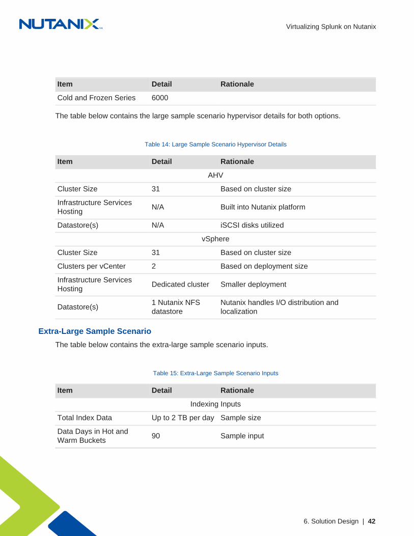
Item Detail Rationale
Cold and Frozen Series 6000
The table below contains the large sample scenario hypervisor details for both options.
Table 14: Large Sample Scenario Hypervisor Details
Item Detail Rationale
AHV
Cluster Size 31 Based on cluster size
Infrastructure ServicesHosting
N/A Built into Nutanix platform
Datastore(s) N/A iSCSI disks utilized
vSphere
Cluster Size 31 Based on cluster size
Clusters per vCenter 2 Based on deployment size
Infrastructure ServicesHosting
Dedicated cluster Smaller deployment
Datastore(s)1 Nutanix NFSdatastore
Nutanix handles I/O distribution andlocalization
Extra-Large Sample Scenario
The table below contains the extra-large sample scenario inputs.
Table 15: Extra-Large Sample Scenario Inputs
Item Detail Rationale
Indexing Inputs
Total Index Data Up to 2 TB per day Sample size
Data Days in Hot andWarm Buckets
90 Sample input

Virtualizing Splunk on Nutanix
6. Solution Design | 43
Item Detail Rationale
Data Days in Cold andFrozen Buckets
365 Sample input
Min. # of Hot and WarmIndexers
22 mediumBased on daily indexing and hot and warmbucket storage
Min. # of Cold and FrozenNodes and Indexers
34 mediumBased on daily indexing and cold and frozenbucket storage
Search Inputs
Search Users Up to 96 Sample size
# of Search Heads 7 medium Minimum recommended
The table below contains the extra-large sample scenario platform details and features.
Table 16: Extra-Large Sample Scenario Platform Details
Item Detail Rationale
Splunk Features
Distributed Deployment No VM HA
Search Head Pooling No Not recommended
Search Head Clustering Yes Preferred approach
Nutanix
Min. # of Nodes 63 Minimum number of nodes
# of Cluster(s) 2 Isolated fault domains
Platform
Hot and Warm Series 3000, 8000
Cold and Frozen Series 6000
The table below contains the extra-large sample scenario hypervisor details for both options.

Virtualizing Splunk on Nutanix
6. Solution Design | 44
Table 17: Extra-Large Sample Scenario Hypervisor Details
Item Detail Rationale
AHV
Cluster Size 32 Isolated fault domains
Infrastructure ServicesHosting
N/A Built into Nutanix platform
Datastore(s) N/A iSCSI disks utilized
vSphere
Cluster Size 32 Isolated fault domains
Clusters per vCenter 2 Task parallelization
Infrastructure ServicesHosting
Dedicated cluster Smaller deployment
Datastore(s)2 Nutanix NFSdatastores
Nutanix handles I/O distribution andlocalization
Additional Sizing Considerations When Running Splunk Enterprise Security
Please consult the latest Splunk ES deployment planning guide. Currently, each Splunk ESindexer and each Splunk ES search head requires at least 16 vCPUs and 32 GB of RAM. EachSplunk ES indexer can support a maximum of 100 GB of daily ingest.
Data model acceleration can speed up the data modeling of extremely large datasets. Thistoolset creates data summaries (pivot tables) from the underlying dataset to update and completeitems such as reports and dashboards more quickly. Splunk provides data model accelerationusing the high-performance analytics store functionality, which builds and stores data summarieson the indexer VMs parallel to the index buckets containing the summarized events.
Please consult the latest guide for configuring data models for Splunk ES. Currently, the defaultsettings for data model acceleration require a minimum of 3.4 times the daily ingest rate of SSDspace to support this feature. This SSD space is above and beyond what is required to storeyour hot buckets. The Splunk guide also describes how to limit data model acceleration to certainindexes and shorten retention periods to reduce disk space requirements.
Note: Accelerated data model storage per year = data volume per day x 3.4
Splunk ES can also use custom data models. If you’re using custom models in addition to thoseprovided by the standard Splunk Common Information Model (CIM), you may need to increasethe storage requirements further.

Virtualizing Splunk on Nutanix
6. Solution Design | 45
The following working example shows the various storage requirements for a comprehensiveSplunk Enterprise Security deployment. We based these calculations on feedback from ourSplunk customers.
• Assumptions underlying this example Splunk ES environment:
# 1 TB raw ingest per day, resulting in 500 GB per day on disk (in other words, 50 percentSplunk compression savings).
# 10 indexer VMs (1 per 100 GB ingest), each with 16 vCPUs and 32 GB RAM.
# 30 days hot, 60 days warm, 270 days cold.
# Data model acceleration enabled with default settings.
• Required SSD space for hot data:
# Day 1 = 1 TB
# Day 2 = 1 TB
# Days 3–30 = 500 GB x 28 = 14 TB
# Data Model Acceleration = 3.4 x 1 TB = 3.4 TB
# Total SSD space in the cluster required for hot data = 1 + 1 + 14 + 3.4 = ~20 TB minimum
This SSD space requirement assumes that the system retains such accelerated data models forthe same amount of time as the hot query tier (for example, 30 days). Splunk’s deployment guiderecommends 3.4 times the daily ingest rate of SSD space for data model acceleration alone,but this allotment doesn’t account for other features that could also use the high-performanceanalytics store.
• Required HDD space for warm data:
# Days 31–90 = 60 x 500 GB = 30 TB
# On larger Splunk deployments with an active warm data tier, Nutanix strongly recommendsthe NX-6155-G5 or NX-8150-G5 platform to ensure that enough HDD spindles areavailable to serve up IOPS for queries that spill out of the SSD tier.
• Required HDD space for cold data:
# Days 91–360 = 270 x 500 GB = 135 TB
# With Nutanix post-process compression enabled (48-hour delay), you can see additionalspace savings on cold data in the neighborhood of 20 percent, depending on your data andenvironment.
• Total Splunk Enterprise Security datastore size = 185 TB

Virtualizing Splunk on Nutanix
6. Solution Design | 46
6.4. Nutanix Compute and StorageThe Nutanix Enterprise Cloud OS provides an ideal combination of high-performance computewith localized storage to meet any demand. True to this capability, this reference architecturecontains zero reconfiguration of or customization to the Nutanix product to optimize for this usecase.
The figure below shows a high-level example of the relationship between a Nutanix block, node,storage pool, and container.
Figure 21: Nutanix Logical Layout
The following table provides the Nutanix storage pool and container configuration.
Table 18: Nutanix Container Configuration
Name Role Details
SP01 Main storage pool for all data All disks
CTR-VM-DATA Container for all VMs and OS VM and index data
6.5. NetworkNutanix recommends a leaf-spine network architecture because it is designed for true linearscaling. A leaf-spine architecture consists of two network tiers: an L2 leaf and an L3 spine basedon 40 GbE and nonblocking switches. This architecture maintains consistent performancewithout any throughput reduction because it has a single hop for communication—from any leaf(node) to the spine to any other leaf.

Virtualizing Splunk on Nutanix
6. Solution Design | 47
The figure below shows a design of a scale-out leaf-spine network architecture that provides20 Gb active throughput from each node to its L2 leaf and scalable 80 Gb active throughputfrom each leaf-to-spine switch, providing scale from one Nutanix block to thousands without anyimpact to available bandwidth.
Figure 22: Leaf-Spine Network Architecture
Virtualizing Splunk on Nutanix
7. Validation and Benchmarking | 48
7. Validation and Benchmarking
We conducted the solution and testing in this document with Splunk 6.4.3 deployed on NutanixAHV 20160217.2 running Nutanix AOS. We used the SplunkIT benchmark to detail indexingperformance and the Bonnie++ and IOzone benchmarks to detail storage performance on theNutanix appliance.
7.1. Environment OverviewThe target environment was a Nutanix NX-3460, which provided all Splunk hosting. The Nutanixblock was connected to an Arista 7050S top-of-rack switch via 10 GbE.
Test Environment Configuration
Assumptions:
• Bonnie++ I/O size: 2 memory
• Disk configurations:
# Non-LVM: 1
# LVM: 1, 2, 4, 6
Hardware:
• Storage and compute: 1 Nutanix NX-3460
• Network: Arista 7050Q (L3 spine) and 7050S (L2 leaf) series switches
Nutanix:
• AOS Version: 5.0.1
• AHV: 20160217.2
Splunk VM Configuration:
• OS: CentOS
• CPU and memory: 8 vCPUs and 8 GB
• Disk:
# 1x 40 GB (OS)
# 6x 200 GB (Data)
• Application Version: 6.4.3 (build b03109c2bad4)
Virtualizing Splunk on Nutanix
7. Validation and Benchmarking | 49
Bonnie++:
• Version: 1.97.3
• Data size: 2 memory per thread
Virtualizing Splunk on Nutanix
7. Validation and Benchmarking | 50
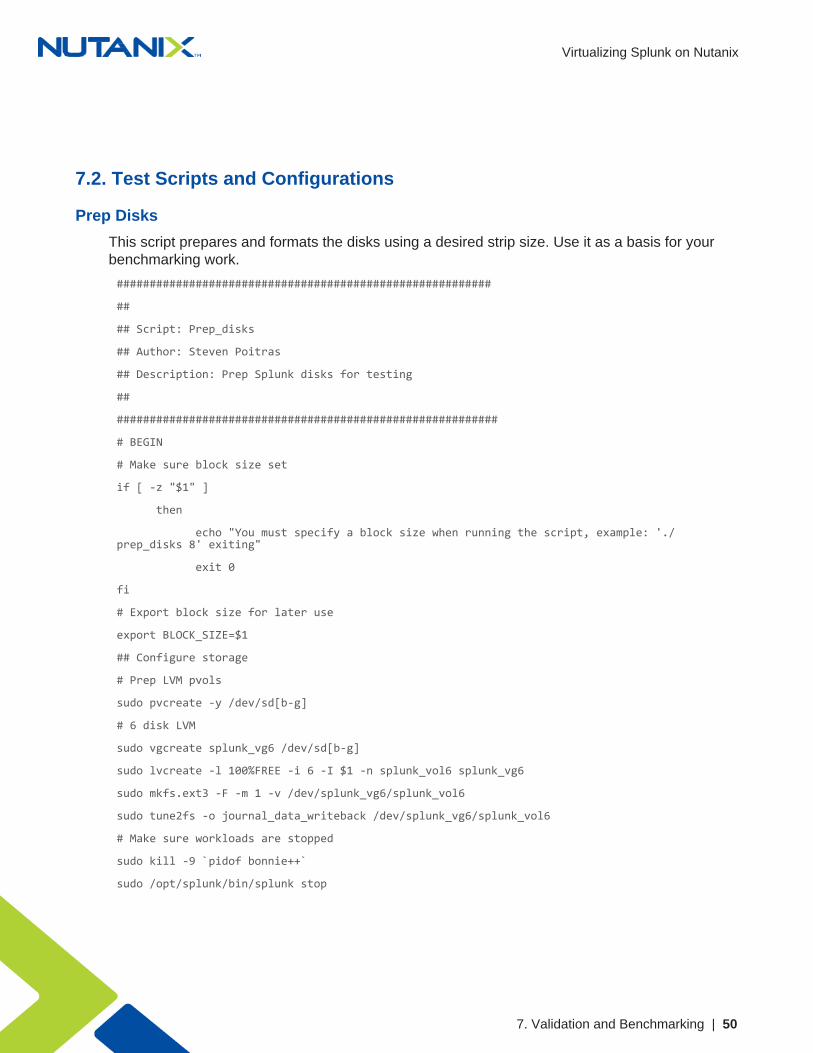
7.2. Test Scripts and Configurations
Prep Disks
This script prepares and formats the disks using a desired strip size. Use it as a basis for yourbenchmarking work.
#########################################################
##
## Script: Prep_disks
## Author: Steven Poitras
## Description: Prep Splunk disks for testing
##
##########################################################
# BEGIN
# Make sure block size set
if [ -z "$1" ]
then
echo "You must specify a block size when running the script, example: './prep_disks 8' exiting"
exit 0
fi
# Export block size for later use
export BLOCK_SIZE=$1
## Configure storage
# Prep LVM pvols
sudo pvcreate -y /dev/sd[b-g]
# 6 disk LVM
sudo vgcreate splunk_vg6 /dev/sd[b-g]
sudo lvcreate -l 100%FREE -i 6 -I $1 -n splunk_vol6 splunk_vg6
sudo mkfs.ext3 -F -m 1 -v /dev/splunk_vg6/splunk_vol6
sudo tune2fs -o journal_data_writeback /dev/splunk_vg6/splunk_vol6
# Make sure workloads are stopped
sudo kill -9 `pidof bonnie++`
sudo /opt/splunk/bin/splunk stop

Virtualizing Splunk on Nutanix
7. Validation and Benchmarking | 51
# Unmount & cleanup directories
sudo umount /mnt/6vd_lvm && sudo rmdir /mnt/6vd_lvm
# Make directories
sudo mkdir /mnt/6vd_lvm
# Write mounts to fstab
echo "/dev/splunk_vg6/splunk_vol6 /mnt/6vd_lvm ext4 noatime,data=writeback,barrier=0,nobh,errors=remount-ro 0 1" | sudo tee -a /etc/fstab
# Mount
sudo mount -a
# Change permissions
sudo chmod 777 /mnt/*vd*
# END

Virtualizing Splunk on Nutanix
7. Validation and Benchmarking | 52
Execute Bonnie++ Tests
This script executes the Bonnie++ tests using the six-disk LVM volume previously created. Use itas a basis for your benchmarking work.
#########################################################
##
## Script: Exec_Bonnie
## Author: Steven Poitras
## Description: Run Bonnie++ tests
##
##########################################################
# BEGIN
# Make bonnie++ results folder
mkdir ~/bonnieResults
##################
## 6 disk tests ##
##################
#echo "Running 6 disk 1 thread test..."
#bonnie++ -d /mnt/6vd_lvm/ -x 1 -qfb | bon_csv2html > ~/bonnieResults/6vd_1thread.html &
# Sleep
sleep 10m
# 6 threads
echo "Running 6 disk 6 thread test..."
bonnie++ -p 6
bonnie++ -d /mnt/6vd_lvm/ -x 1 -qfby > /mnt/6vd_lvm/out1 &
bonnie++ -d /mnt/6vd_lvm/ -x 1 -qfby > /mnt/6vd_lvm/out2 &
bonnie++ -d /mnt/6vd_lvm/ -x 1 -qfby > /mnt/6vd_lvm/out3 &
bonnie++ -d /mnt/6vd_lvm/ -x 1 -qfby > /mnt/6vd_lvm/out4 &
bonnie++ -d /mnt/6vd_lvm/ -x 1 -qfby > /mnt/6vd_lvm/out5 &
bonnie++ -d /mnt/6vd_lvm/ -x 1 -qfby > /mnt/6vd_lvm/out6 &
# Sleep
sleep 10m
# Format results
cat /mnt/6vd_lvm/out1 /mnt/6vd_lvm/out2 /mnt/6vd_lvm/out3 /mnt/6vd_lvm/out4
Virtualizing Splunk on Nutanix
7. Validation and Benchmarking | 53
/mnt/6vd_lvm/out5 /mnt/6vd_lvm/out6 | bon_csv2html > ~/bonnieResults/6vd_6threads.html
# Compress test results
now=$(date +"%m_%d_%Y")
tar -zcvf $BLOCK_SIZE-K-bonnieResults__$now.tar.gz ~/bonnieResults/
# END
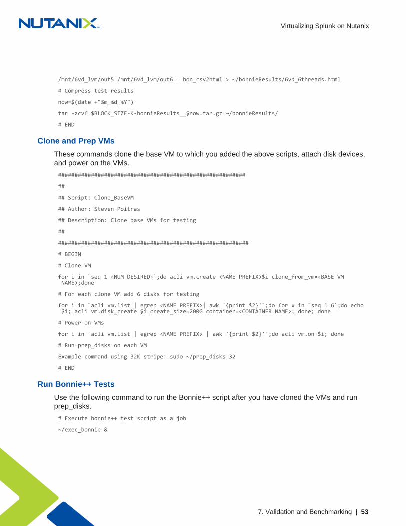
Clone and Prep VMs
These commands clone the base VM to which you added the above scripts, attach disk devices,and power on the VMs.
#########################################################
##
## Script: Clone_BaseVM
## Author: Steven Poitras
## Description: Clone base VMs for testing
##
##########################################################
# BEGIN
# Clone VM
for i in `seq 1 <NUM DESIRED>`;do acli vm.create <NAME PREFIX>$i clone_from_vm=<BASE VM NAME>;done
# For each clone VM add 6 disks for testing
for i in `acli vm.list | egrep <NAME PREFIX>| awk '{print $2}'`;do for x in `seq 1 6`;do echo $i; acli vm.disk_create $i create_size=200G container=<CONTAINER NAME>; done; done
# Power on VMs
for i in `acli vm.list | egrep <NAME PREFIX> | awk '{print $2}'`;do acli vm.on $i; done
# Run prep_disks on each VM
Example command using 32K stripe: sudo ~/prep_disks 32
# END
Run Bonnie++ Tests
Use the following command to run the Bonnie++ script after you have cloned the VMs and runprep_disks.
# Execute bonnie++ test script as a job
~/exec_bonnie &
Virtualizing Splunk on Nutanix
7. Validation and Benchmarking | 54
7.3. Benchmarks
SplunkIT Benchmark
SplunkIT is a tool for benchmarking and comparing Splunk indexing and search performance.
The test benchmark consists of the following main phases:
• Generate Data: Generate n GB of syslog data (default = 50 GB).
• Index Test: Measure the time it takes to index n GB of syslog data.
• Search Test: Measure the time it takes to search using Splunk Web.
For more information about SplunkIT, visit the Splunk Performance Blog.
Bonnie++ Benchmark
Bonnie++ is a tool for benchmarking file system and storage subsystem performance. Alsoused to identify the optimal RAID or LVM configuration and disk quantity for arrays, it is a keybenchmark when analyzing suitability for running Splunk and its I/O patterns.
The test benchmark consists of the following main phases:
• Sequential Output: Writing a sequential stream of data.
• Sequential Input: Reading a sequential stream of data.
• Random Seeks: Reading random data.
For more information or to download Bonnie++, visit https://www.coker.com.au/bonnie++/.
7.4. How to Interpret the Results
SplunkIT Metrics
The following metrics quantify evaluation:
• Throughput (KBps): The amount of data input read per second.
• Events per second (EPS): The amount number of events indexed per second.
• Time to first event (TFE): The time it takes to return the first event from search.
• Time to search (TTS): The time it takes to return all events from search.
Drawing on user experience and industry standards, we recommend keeping the ranges forthese values in line with those provided in the following table.

Virtualizing Splunk on Nutanix
7. Validation and Benchmarking | 55
Table 19: SplunkIT Metric Values
Metric Value Rationale
Throughput (KBps) > 10,000 Acceptable input performance
Events per second (EPS) > 20,000Acceptable indexingperformance
Time to first event (TFE) < 5 Acceptable peak response time
Time to search (TTS) < 30 Acceptable ideal response time
Bonnie++ Metrics
The following metrics quantify evaluation:
• Sequential Output—Block (KB/sec): The number of kilobytes written per second.
• Sequential Output—Rewrite (KB/sec): The number of kilobytes rewritten per second.
• Sequential Input—Block (KB/sec): The number of kilobytes read per second.
• Random Seeks (Num/sec): The number of random seeks per second.
Drawing on user experience and industry standards, we recommend keeping the ranges forthese values in line with those provided in the following table.
Table 20: Bonnie++ Metric Values
Metric Value Rationale
Sequential Output—Block > 100 MBps Affects data input rate
Sequential Output—Rewrite 30–50 MBps Affects index performance
Sequential Input—Block > 100 MBps Affects index performance
Random Seeks > 1,200 Affects search performance
7.5. Results
Bonnie++ Results
The Bonnie++ results showed ample bandwidth and seeks showed approximately 681 MBps forsequential write and approximately 692 MBps for read for a single VM with eight vCPUs and 8
Virtualizing Splunk on Nutanix
7. Validation and Benchmarking | 56
GB of memory. The random seeks were approximately 33,564 seeks per second for a single VMon one node.
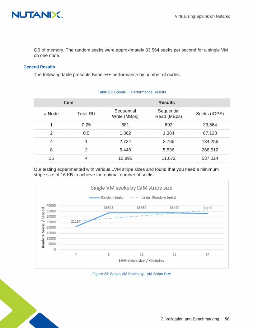
General Results
The following table presents Bonnie++ performance by number of nodes.
Table 21: Bonnie++ Performance Results
Item Results
# Node Total RUSequential
Write (MBps)Sequential
Read (MBps)Seeks (IOPS)
1 0.25 681 692 33,564
2 0.5 1,362 1,384 67,128
4 1 2,724 2,786 134,256
8 2 5,448 5,536 268,512
16 4 10,896 11,072 537,024
Our testing experimented with various LVM stripe sizes and found that you need a minimumstripe size of 16 KB to achieve the optimal number of seeks.
Figure 23: Single VM Seeks by LVM Stripe Size

Virtualizing Splunk on Nutanix
7. Validation and Benchmarking | 57
From a sequential throughput perspective, a 64 KB LVM stripe size offered the best blend of readand write performance.
Figure 24: Single VM Throughput by LVM Stripe Size
Based on the results for seeks and sequential throughput, we recommend using a 32 KB or 64KB LVM stripe size.
The following graph shows that six disks is the ideal number in an LVM volume to maximize bothread and write performance.
Figure 25: Single VM Throughput by Number of Disks

Virtualizing Splunk on Nutanix
7. Validation and Benchmarking | 58
Sequential Throughput
The following chart shows the Bonnie++ sequential throughput for both write (put_block) andread (get_block) throughput.
Sequential write throughput was approximately 2,724 MBps for four indexers or nodes andapproximately 5,541 MBps for eight indexers or nodes. Sequential read performance wasapproximately 2,724 MBps and 5,488 MBps, respectively.
Figure 26: Single VM Throughput by Number of Indexers
Note: The chart above assumes one indexer per node.
Write throughput was approximately 0.68 GBps for a single VM running on a single node,peaking at approximately 10.88 GBps on 16 nodes.
Figure 27: Write Throughput by Number of Nodes

Virtualizing Splunk on Nutanix
7. Validation and Benchmarking | 59
The following figure presents the write throughput by number of RU.
Figure 28: Write Throughput by Number of RU
Read throughput was approximately 0.69 GBps for a single VM running on a single node,peaking at approximately 11.04 GBps on 16 nodes.
Figure 29: Read Throughput by Number of Nodes
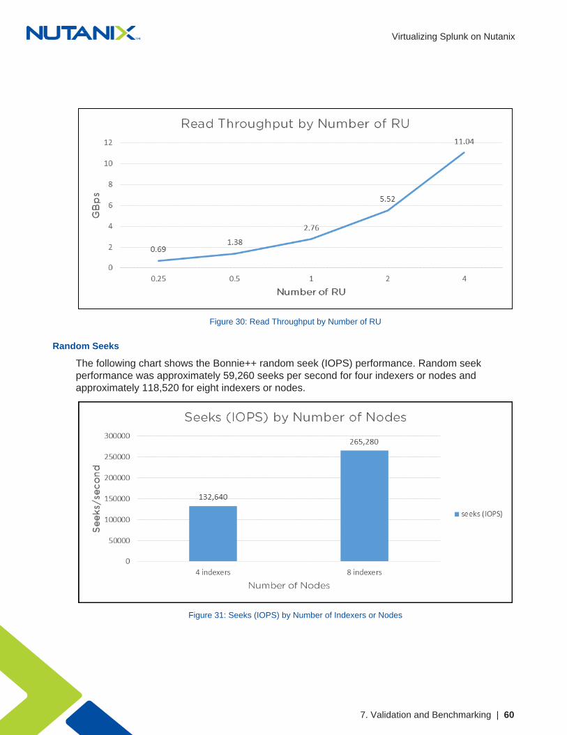
The following figure presents the read throughput by number of RU.
Virtualizing Splunk on Nutanix
7. Validation and Benchmarking | 60
Figure 30: Read Throughput by Number of RU
Random Seeks
The following chart shows the Bonnie++ random seek (IOPS) performance. Random seekperformance was approximately 59,260 seeks per second for four indexers or nodes andapproximately 118,520 for eight indexers or nodes.
Figure 31: Seeks (IOPS) by Number of Indexers or Nodes

Virtualizing Splunk on Nutanix
7. Validation and Benchmarking | 61
Random seeks were approximately 33,160 per second for a single VM running on a single node,peaking at approximately 530,560 seeks per second on 16 nodes.
Figure 32: Seeks by Number of Nodes
The following chart presents the random seeks by number of RU.

Virtualizing Splunk on Nutanix
8. From Bare Metal to Nutanix: A Brief Customer Case Study | 62
8. From Bare Metal to Nutanix: A Brief CustomerCase Study
The following graphs demonstrate the potential benefits of migrating a Splunk deploymentrunning on bare metal servers to the Nutanix Enterprise Cloud. This customer in the financialtechnology space ran Splunk for log analysis of machine-generated data and periodically usedthe Splunk Enterprise Search functionality.
They tested a four-node Splunk (6.3.1) indexer cluster running in two different configurations:
• Bare Metal: 4 HP Proliant, dual E5-2665
# local DAS (24x 15 KB SAS disks)
# 16 cores and 32 GB RAM per host
• Nutanix: 1 NX-3460-G4 chassis (four nodes) dual E5-2680v4
# 2 SSD and 4 HDD per node
# 12 vCPUs and 18 GB RAM per VM
Note: Splunk search metrics summary: four times faster with 1:1 vCPU:CPU , twoto three times faster with 2:1 vCPU:CPU oversubscription.
Figure 33: CPU Utilization on Bare Metal Deployment

Virtualizing Splunk on Nutanix
8. From Bare Metal to Nutanix: A Brief Customer Case Study | 63
Figure 34: CPU Utilization After Migrating Indexers to Nutanix Enterprise Cloud Platform
The two graphs above show the CPU utilization before and after migration to the Nutanixplatform. While overall the CPU utilization is lower and considerably “smoothed” on Nutanix, theaverage wait I/O metric is dramatically reduced—by almost four times. The customer interpretedthis improvement to mean that a Splunk process could do more actual work when scheduled ona processor.
The next two graphs show the increase in IOPS after migration to Nutanix. The Nutanix tieringalgorithms ensure that the Splunk search and indexing processes continually access the SSD hottier to ensure the most responsive I/O profile. The difference in results before and after migrationis quite stark, with the Splunk processes on Nutanix achieving upward of 16,000 IOPS. Again,this means that running Splunk on Nutanix enables approximately four times the IOPS thatrunning on bare metal does.
Figure 35: IOPS for Indexer Cluster Running on Bare Metal

Virtualizing Splunk on Nutanix
8. From Bare Metal to Nutanix: A Brief Customer Case Study | 64
Figure 36: IOPS for Same Indexer Cluster After Migration to the Nutanix Enterprise Cloud

Virtualizing Splunk on Nutanix
9. Conclusion | 65
9. Conclusion
With Nutanix, customers can start their Splunk deployments small and then scale out theinfrastructure as needed to meet data ingest and retention requirements. The Nutanix EnterpriseCloud ensures that the system remains available, providing consistent ingest, indexing, andsearch performance. Administrators can focus on Splunk and their applications, not on theinfrastructure, transparently adding compute and storage resources to the cluster as theenvironment grows.
The Splunk on Nutanix solution provides a single high-density platform for Splunk, VM hosting,and application delivery. Whatever your company’s requirements, there are a range of Nutanixmodels to choose from.
For Nutanix or Splunk on Nutanix questions, please use our Nutanix Next Community. Follow uson Twitter @nutanix.

Virtualizing Splunk on Nutanix
Appendix | 66
Appendix
References1. Splunk Enterprise Distributed Deployment Manual2. Splunk Enterprise Multisite indexer cluster deployment overview3. Splunk Enterprise Deployment planning4. Nutanix Controller VM Failure documentation5. Nutanix Host Failure documentation6. Splunk Enterprise What happens when the master node goes down7. Splunk Enterprise Configure data models for Splunk Enterprise Security
About the AuthorRay Hassan is part of the Global Performance and Solutions Engineering team at Nutanix. Heoriginally joined Nutanix as the first systems reliability engineer based outside the company’sSan Jose headquarters. In his current role, Ray focuses on next generation and emergingtechnologies, including such areas as containers, NoSQL databases, big data, and search. Hedevelops reference architectures, best practice guides, white papers, and more on how to makenext generation applications integrate and perform best on the Nutanix platform. Before joiningNutanix, he spent over 10 years as a sustaining engineer for clustering and storage technologies.Follow Ray on Twitter @cannybag.
About NutanixNutanix makes infrastructure invisible, elevating IT to focus on the applications and services thatpower their business. The Nutanix Enterprise Cloud OS leverages web-scale engineering andconsumer-grade design to natively converge compute, virtualization, and storage into a resilient,software-defined solution with rich machine intelligence. The result is predictable performance,cloud-like infrastructure consumption, robust security, and seamless application mobility for abroad range of enterprise applications. Learn more at www.nutanix.com or follow us on Twitter@nutanix.

Virtualizing Splunk on Nutanix
67
List of Figures
Figure 1: Nutanix Enterprise Cloud................................................................................... 7
Figure 2: Splunk + Nutanix High-Level Architecture....................................................... 12
Figure 3: DSF I/O Path, Fingerprinting, and the Content Cache.....................................14
Figure 4: Mapping Splunk Index Buckets to Nutanix ILM............................................... 15
Figure 5: Splunk ILM Series Mapping.............................................................................16
Figure 6: Data Protection: Traditional Replication Factors..............................................17
Figure 7: Erasure-Coded Strip........................................................................................ 18
Figure 8: Erasure-Coded Strip Savings...........................................................................19
Figure 9: Disk Balancing: Unbalanced............................................................................ 20
Figure 10: Disk Balancing: Balanced.............................................................................. 21
Figure 11: Disk Balancing: Storage-Only Node...............................................................21
Figure 12: High-Level Data I/O Path...............................................................................22
Figure 13: Data I/O Path: Detailed..................................................................................23
Figure 14: Nonclustered Deployment.............................................................................. 24
Figure 15: Search Head Cluster Deployment................................................................. 25
Figure 16: Multiple Indexer Cluster Architecture Across Two Sites.................................26
Figure 17: Splunk Site Replication Factor Changes on Nutanix..................................... 27
Figure 18: Nutanix Cluster Hosting Splunk VMs.............................................................27
Figure 19: Nutanix Autopath Redirects I/O on CVM Failure........................................... 28
Figure 20: Nutanix HA Live Migrates Application VMs on Cluster Host Failure...............29
Figure 21: Nutanix Logical Layout...................................................................................46

Virtualizing Splunk on Nutanix
68
Figure 22: Leaf-Spine Network Architecture................................................................... 47
Figure 23: Single VM Seeks by LVM Stripe Size............................................................56
Figure 24: Single VM Throughput by LVM Stripe Size................................................... 57
Figure 25: Single VM Throughput by Number of Disks...................................................57
Figure 26: Single VM Throughput by Number of Indexers..............................................58
Figure 27: Write Throughput by Number of Nodes......................................................... 58
Figure 28: Write Throughput by Number of RU.............................................................. 59
Figure 29: Read Throughput by Number of Nodes.........................................................59
Figure 30: Read Throughput by Number of RU..............................................................60
Figure 31: Seeks (IOPS) by Number of Indexers or Nodes............................................60
Figure 32: Seeks by Number of Nodes...........................................................................61
Figure 33: CPU Utilization on Bare Metal Deployment................................................... 62
Figure 34: CPU Utilization After Migrating Indexers to Nutanix Enterprise Cloud Platform 63
Figure 35: IOPS for Indexer Cluster Running on Bare Metal..........................................63
Figure 36: IOPS for Same Indexer Cluster After Migration to the Nutanix EnterpriseCloud............................................................................................................................64

Virtualizing Splunk on Nutanix
69
List of Tables
Table 1: Document Version History.................................................................................. 6
Table 2: General Design Decisions.................................................................................30
Table 3: Hypervisor Specific Decisions........................................................................... 31
Table 4: Splunk Indexer VM Sizing.................................................................................32
Table 5: Splunk Search Head VM Sizing........................................................................33
Table 6: Small Sample Scenario Inputs..........................................................................37
Table 7: Small Sample Scenario Platform Details.......................................................... 38
Table 8: Small Sample Scenario Hypervisor Details.......................................................38
Table 9: Medium Sample Scenario Inputs...................................................................... 39
Table 10: Medium Sample Scenario Platform Details.....................................................39
Table 11: Medium Sample Scenario Hypervisor Details................................................. 40
Table 12: Large Sample Scenario Inputs........................................................................41
Table 13: Large Sample Scenario Platform Details........................................................ 41
Table 14: Large Sample Scenario Hypervisor Details.....................................................42
Table 15: Extra-Large Sample Scenario Inputs.............................................................. 42
Table 16: Extra-Large Sample Scenario Platform Details...............................................43
Table 17: Extra-Large Sample Scenario Hypervisor Details........................................... 44
Table 18: Nutanix Container Configuration..................................................................... 46
Table 19: SplunkIT Metric Values................................................................................... 55
Table 20: Bonnie++ Metric Values.................................................................................. 55
Table 21: Bonnie++ Performance Results...................................................................... 56