virtualm : a e framework for w m n omnet++ … · virtualmesh: an emulation framework for wireless...
TRANSCRIPT

VIRTUALMESH: AN EMULATION FRAMEWORKFOR WIRELESS MESH NETWORKS IN
OMNET++
Master Thesisof the Philosophical-scientific Faculty
of the University of Bern
written by
Reto Gantenbein2010
Supervisors:Professor Dr. Torsten Braun
Thomas StaubInstitute of Computer Science and Applied Mathematics


Abstract
Wireless Mesh Networks (WMN) have proven to be an important technology for interconnect-ing computer systems in a flexible way. There exist many application areas that profit fromWMN technologies such as surveillance and monitoring systems, the wireless integration ofmobile clients into a network infrastructure or simply the spontaneous setup of a network fordata exchange between several mobile devices. The development process for new protocols andarchitectures in the area of WMN is typically split into a first implementation and evaluationphase performed with help of a network simulation, followed by a real-world prototype im-plementation, which is tested in a realistic test-bed. Especially for WMNs including wirelesscommunication and mobile clients, the testing in a real test-bed is time-consuming and expen-sive. External interferences can occur and make debugging and performance evaluation difficult.Additionally, real-world test-beds usually only support a limited number of test topologies andwireless clients and rarely provide the possibility for repeatable experiments with mobile clients.
For this reason, we developed VirtualMesh, a new WMN evaluation framework providing avirtual wireless network, which can be used for network protocol and application developmentbefore considering a real hardware test-bed. Its architecture offers the testing of real communi-cation software including the operating system with the original network stack in a controlledenvironment. The wireless communication is handled by a real-time network emulation, whichcan imitate complex network scenarios in an inexpensive way. VirtualMesh captures the realnetwork traffic through a virtual wireless interface at the mesh clients and redirects it to a wire-less model based on the OMNeT++ network simulator. The simulator, which is responsible forthe wireless emulation, computes the node connectivity and packet latency and forwards thetraffic to the destination nodes accordingly. To be able to imitate a truly dynamic network en-vironment, which even allow the reconfiguration of wireless parameters by routing protocols orapplications, a sophisticated mechanism in VirtualMesh allows the corresponding adaptation ofthe wireless settings inside the simulation model during emulation run-time.
In our experiments, VirtualMesh has proven to be very flexible and scalable in the networkscenario. It is able to perfectly imitate the throughput behaviour in a WMN and only introduces asmall packet delay mainly caused by the distributed emulation setup. VirtualMesh has thereforeproven to be a valuable tool for protocol and application developers to test their real-worldimplementation in a controllable environment prior to the final development.
i


Acknowledgement
First of all, I would like to express my gratitude to Prof. Dr. Torsten Braun for giving me thepossibility to do this work in his ‘Computer Networks and Distributed Systems’ research group.He has always been patient and supportive during the course of this Master thesis and his pre-sentation of VirtualMesh on the OMNeT++ Workshop in Rome last year was very encouragingfor me.
Special thanks also to my thesis advisor Thomas Staub who spent much effort in shapingVirtualMesh for scientific publication what resulted in two released papers. Furthermore, I’mvery thankful for his patience and believe in VirtualMesh as well as his assistance in polishingmy thesis.
Many thanks also to my study friends, especially Daniel Balsiger, Philipp Bunge, DavidGurtner, Michael Lustenberger, Stefan Ott, and Anselm Strauss, always willing to listen to myproblems when I approached them with technical questions or asked for their opinions. I learnta lot of details and procedures in our countless discussions.
My biggest thanks go to my girlfriend Sylvia Low, my whole family, and long-time friends,who always believed in me and supported me, even I often neglected them for my study. Thiseffort would not have been possible without you.
Reto GantenbeinJune 2010
iii


Contents
1 Introduction 11.1 Short History of Wireless Networking . . . . . . . . . . . . . . . . . . . . . . 11.2 Wireless Mesh Networks . . . . . . . . . . . . . . . . . . . . . . . . . . . . . 21.3 Computer Network Evaluation . . . . . . . . . . . . . . . . . . . . . . . . . . 31.4 Motivation . . . . . . . . . . . . . . . . . . . . . . . . . . . . . . . . . . . . . 41.5 Document Structure . . . . . . . . . . . . . . . . . . . . . . . . . . . . . . . . 5
2 Related Work 72.1 Computer Simulations . . . . . . . . . . . . . . . . . . . . . . . . . . . . . . 7
2.1.1 Network Simulation Basics . . . . . . . . . . . . . . . . . . . . . . . . 82.1.2 Radio Propagation Models . . . . . . . . . . . . . . . . . . . . . . . . 92.1.3 The OMNeT++ Network Simulation Framework . . . . . . . . . . . . 11
2.2 Network Emulation . . . . . . . . . . . . . . . . . . . . . . . . . . . . . . . . 142.2.1 Emulation Basics . . . . . . . . . . . . . . . . . . . . . . . . . . . . . 142.2.2 Simulation Requirements for Real-Time Emulation . . . . . . . . . . . 152.2.3 Emulation-based Wireless Network Evaluation . . . . . . . . . . . . . 17
2.3 Real-world Wireless Network Test-beds . . . . . . . . . . . . . . . . . . . . . 202.3.1 Examples of Real-world Test-beds . . . . . . . . . . . . . . . . . . . . 212.3.2 ADAM - A Linux Environment for WMN Research . . . . . . . . . . 21
2.4 Operating System Virtualization . . . . . . . . . . . . . . . . . . . . . . . . . 222.4.1 Platform Virtualization Overview . . . . . . . . . . . . . . . . . . . . 222.4.2 Virtualization and Network Evaluation . . . . . . . . . . . . . . . . . . 24
3 VirtualMesh: An Approach of Wireless Network Emulation 253.1 VirtualMesh Architecture and Design . . . . . . . . . . . . . . . . . . . . . . 253.2 Communication Protocol for the Wireless Emulation . . . . . . . . . . . . . . 28
3.2.1 Protocol Messages . . . . . . . . . . . . . . . . . . . . . . . . . . . . 293.2.2 Message Flow of the Emulation Protocol . . . . . . . . . . . . . . . . 31
3.3 Virtualization in VirtualMesh . . . . . . . . . . . . . . . . . . . . . . . . . . . 31
4 VirtualMesh: Client Implementation 334.1 Client Architecture and Design . . . . . . . . . . . . . . . . . . . . . . . . . . 334.2 vif-Tools . . . . . . . . . . . . . . . . . . . . . . . . . . . . . . . . . . . . . . 35
4.2.1 libvif - Virtual Interface Library . . . . . . . . . . . . . . . . . . . . . 36
v

4.2.2 vifctl - Virtual Interface Control . . . . . . . . . . . . . . . . . . . . . 394.3 iwconnect . . . . . . . . . . . . . . . . . . . . . . . . . . . . . . . . . . . . . 404.4 Virtual Interface Configuration . . . . . . . . . . . . . . . . . . . . . . . . . . 41
4.4.1 Linux Wireless Tools . . . . . . . . . . . . . . . . . . . . . . . . . . . 414.4.2 Changing Simulation Parameters from the Wireless Node . . . . . . . . 42
5 VirtualMesh: Wireless Simulation Server 455.1 WlanModel Components . . . . . . . . . . . . . . . . . . . . . . . . . . . . . 45
5.1.1 EmulationRTScheduler . . . . . . . . . . . . . . . . . . . . . . . . . . 465.1.2 ProtocolHandler . . . . . . . . . . . . . . . . . . . . . . . . . . . . . 485.1.3 NodeManager . . . . . . . . . . . . . . . . . . . . . . . . . . . . . . . 485.1.4 VirtualHost . . . . . . . . . . . . . . . . . . . . . . . . . . . . . . . . 485.1.5 VifBackend . . . . . . . . . . . . . . . . . . . . . . . . . . . . . . . . 495.1.6 RAWEtherFrame . . . . . . . . . . . . . . . . . . . . . . . . . . . . . 495.1.7 IEEE80211NicAdhoc . . . . . . . . . . . . . . . . . . . . . . . . . . 495.1.8 IEEE80211Radio . . . . . . . . . . . . . . . . . . . . . . . . . . . . . 505.1.9 ChannelControl . . . . . . . . . . . . . . . . . . . . . . . . . . . . . . 505.1.10 Mobility . . . . . . . . . . . . . . . . . . . . . . . . . . . . . . . . . 515.1.11 Simulation Configuration . . . . . . . . . . . . . . . . . . . . . . . . . 51
5.2 WlanModel Message Flow . . . . . . . . . . . . . . . . . . . . . . . . . . . . 515.2.1 Node Registration . . . . . . . . . . . . . . . . . . . . . . . . . . . . 525.2.2 Wireless Traffic Processing . . . . . . . . . . . . . . . . . . . . . . . . 525.2.3 Wireless Parameter Modification . . . . . . . . . . . . . . . . . . . . . 53
6 Evaluation 576.1 VirtualMesh Test Configuration . . . . . . . . . . . . . . . . . . . . . . . . . 586.2 Functional Evaluation: ADAM . . . . . . . . . . . . . . . . . . . . . . . . . . 596.3 Performance Evaluation: Round-Trip Time . . . . . . . . . . . . . . . . . . . 60
6.3.1 Test Procedure . . . . . . . . . . . . . . . . . . . . . . . . . . . . . . 616.3.2 Infrastructure Network Latency . . . . . . . . . . . . . . . . . . . . . 616.3.3 Wireless Emulation Accuracy . . . . . . . . . . . . . . . . . . . . . . 636.3.4 WlanModel Scalability . . . . . . . . . . . . . . . . . . . . . . . . . . 67
6.4 Performance Evaluation: Bandwidth . . . . . . . . . . . . . . . . . . . . . . . 696.4.1 Test Procedure . . . . . . . . . . . . . . . . . . . . . . . . . . . . . . 706.4.2 VirtualMesh Throughput . . . . . . . . . . . . . . . . . . . . . . . . . 70
7 Conclusion and Future Work 737.1 Conclusion . . . . . . . . . . . . . . . . . . . . . . . . . . . . . . . . . . . . 737.2 Future Work . . . . . . . . . . . . . . . . . . . . . . . . . . . . . . . . . . . . 74
A Evaluation Setup 77A.1 Test Machines . . . . . . . . . . . . . . . . . . . . . . . . . . . . . . . . . . . 77A.2 OMNeT++ Configuration for the WlanModel . . . . . . . . . . . . . . . . . . 78A.3 How to create a Xen image with ADAM’s image-tool? . . . . . . . . . . . . . 79
vi
B Evaluation Results 81B.1 Infrastructure Evaluation Results . . . . . . . . . . . . . . . . . . . . . . . . . 81B.2 VirtualMesh Evaluation Results . . . . . . . . . . . . . . . . . . . . . . . . . 84B.3 OMNeT++/INET Simulation Results . . . . . . . . . . . . . . . . . . . . . . . 88
List of Acronyms 91
List of Figures 95
List of Tables 97
Bibliography 101
vii


Chapter 1
Introduction
Nowadays, nearly all of us are regularly using devices which can connect to a network, withoutrequiring a wire. These can be mobile phones, Personal Digital Assistants (PDA), net-books,laptops, or even multimedia players. One get more and more used that every portable device cancommunicate and that it provides the same services as our wired computer, gaming console, orphone. However, developing and evaluating services for such an environment requires sophisti-cated tools for debugging and testing. This Master thesis introduces and evaluates VirtualMesh,a flexible and modular framework for testing new network protocols, applications or even entirenetwork architectures, with focus on wireless mesh networking.
This introductory chapter is divided into several sections approaching the wider domain, ofwhich this thesis is part. After a sum up of the important milestones in the history of wirelessnetworking (Section 1.1), the focus is set on wireless mesh networks (Section 1.2). Section 2.1introduces computer simulation as a basic technology used for network development. Embeddedin these research areas, the VirtualMesh emulation framework is finally motivated in Section 1.4.Eventually, a brief overview about the further chapters of this thesis (Section 1.5) follows.
1.1 Short History of Wireless Networking
The origin of computer networking goes back to the cold war when the US department of defencewanted to create a redundant command network for nuclear warfare. In the 1960’s efforts andideas for creating a distributed computer network were bundled and finally resulted 1969 in thefirst larger scale network, the ARPANET [1]. A few years later, in 1974, Vinton Cerf and RobertKahn published their suggestion for a inter-network communication protocol [2], today betterknown as Transmission Control Protocol (TCP). Since then, the interconnection of computersystems achieved a previously unknown density with its prime example, the Internet. Specialisednetworks as the World Wide Web could only be developed thanks to the approach of individual,service-oriented layers, formally defined in the OSI reference model [3] and technically specifiedin the in the TCP/IP reference model [4]. This layered design allows independent and concurrentdevelopment, testing and deployment of diverse protocols and technologies.
A subtopic of computer network science is wireless communication. First attempts go backto the physicist Guglielmo Marconi who engineered the wireless telegraph with binary Morse
1

transmission in 1899 [5]. Sixty years later, around the same time as the previously mentionedARPANET has evolved, first efforts were made to develop a wireless communication technol-ogy for computer systems. In 1970 Norman Abramson of the University of Hawaii introducedALOHANET [6], in which he linked computers on distinct campus areas with low-cost ama-teur radio-like systems. The late 1970’s are then mostly affected by research on best practisesfor wireless medium access. After first portable computers started to appear in the 1980’s, theIEEE Communication Society started to organise workshops on ’Wireless Local Area Networks’(WLAN) [7] in 1991. At the same time, the newly formed IEEE 802.11 committee started itsongoing activities on the development of standards for WLANs. Their released IEEE standards,namely 802.11b, 802.11g, and 802.11n, are the nowadays most used technologies for wirelesscomputer networking. However, the main usage scenario of the currently approved 802.11 spec-ifications is limited to a central access point (AP), to which all wireless clients connect. IEEEhas also specified the Independent Basic Service Set (IBSS) mode, the so-called ad-hoc mode,with no central instance, but still, ”the IBSS mode is not enough for many application scenar-ios” [8]. Thus, there are new standards in development and therefore particularly interestingfor wireless network research. These are among others, IEEE 802.11s (Mesh networking, cur-rently draft 5.0, started 2003) and IEEE 802.16 (WMAN/WiMAX, drafts started 2001) withmore distributed structures.
1.2 Wireless Mesh Networks
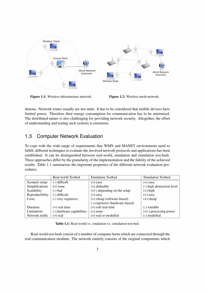
As stated in the previous section, distributed networks, especially Wireless Mesh Net-works (WMN), are growing in attention. Common conservative wireless network topologiesconsist of one or several AP(s), which manage the entire network (Figure 1.1) in respect ofauthorisation, authentication, routing, and quality of service. This centralisation is avoided ina WMN (Figure 1.2). Therein each participating host has equal functionality and responsibil-ities in terms of the network establishment. Such hosts are called wireless nodes or simplynodes hereafter. In a WMN, certain nodes can still be linked to a wired network and providesome gateway functionality. Instead of directly connecting to the AP, a wireless node is able toparticipate in a network, as soon as it is within transmission range of any other node. Sophis-ticated routing algorithms, such as Ad-Hoc On-Demand Distance Vector Routing (AODV) [9]or Optimised Link State Routing (OLSR) [10] allow flexible and dynamic network structureswith self-healing mechanisms around blocked or broken paths. Wireless mesh networks aredecentralised, i.e., a failing node cannot completely tear down the network. This is useful insituations, where a traditional wired network is missing, too expensive, or damaged. A WirelessMetropolitan Area Network (WMAN) is an example for a stationary WMN. Mobile Ad-hocNetworks (MANET) combine the mesh structure of a WMN with totally independent and mo-bile nodes. Their topology can be highly dynamic, with nodes joining and leaving at any suddeninstant. These properties are consequently best suited for totally versatile and reliable commu-nication systems, used in a wide area such as surveillance systems for traffic control or weathermonitoring.
The high degree of flexibility and distribution in a WMN or MANET is challenging andinvolves all layers of networking and applications. Wireless links can be asymmetric or discon-
2
Access Point
Wireless Client
Wired Network
(Internet)
Figure 1.1: Wireless infrastructure network.
Wireless Node
Wired Network
(Internet)
Figure 1.2: Wireless mesh network.
tinuous. Network routes usually are not static. It has to be considered that mobile devices havelimited power. Therefore their energy consumption for communication has to be minimised.The distributed nature is also challenging for providing network security. Altogether, the effortof understanding and testing such systems is enormous.
1.3 Computer Network Evaluation
To cope with the wide range of requirements that WMN and MANET environments need tofulfill, different techniques to evaluate the involved network protocols and applications has beenestablished. It can be distinguished between real-world, emulation and simulation test-beds.These approaches differ by the granularity of the implementation and the fidelity of the achievedresults. Table 1.1 summarises the important properties of the different network evaluation pro-cedures.
Real-world Testbed Emulation Testbed Simulation TestbedScenario setup (-) difficult (+) easy (+) easySimplifications (+) none (+) definable (-) high abstraction levelScalability (-) bad (+/-) depending on the setup (+) highReproducibility (-) difficult (+) easy (+) easyCosts (-) very expensive (+) cheap (software-based)
(-) expensive (hardware-based)(+) cheap
Duration (+) real time (+) soft real-time (-) variableLimitations (-) hardware capabilities (+) none (+/-) processing powerNetwork traffic (+) real (+) real or modelled (-) modelled
Table 1.1: Real-world vs. emulation vs. simulation test-bed.
Real-world test-beds consist of a number of computer hosts which are connected through thereal communication medium. The network entirely consists of the original components which
3

are able to handle any interaction under realistic conditions. This is valuable for studying wirednetwork scenarios, but this approach imposes some drawbacks for wireless network evaluation.As the radio signals can interfere with environmental influences, real-world wireless test-bedslimit the repeatability of experiments and restrict the portability of findings to other environ-ments. Since every network node is represented by a real device, real-world test-beds have alimited scalability caused by high hardware costs and the test-bed complexity. Especially theinclusion of node mobility for evaluating MANETs, require an immense effort to retrieve com-parable test results. Some examples of real-world test-beds are further discussed in Section 2.3.1
In sharp contrast to real-world test-beds, network simulations imitate the entire network rep-resentation, including the communication hosts and channels, in a virtual model. However, theimplementation of the network components often require structural and functional simplifica-tions to reduce the complexity of the evaluation subject (e.g. a protocol implementation or anetwork device). On the other hand, the fully artificial environment of a network simulation pro-vides a controllable and scalable system which also allows complex network topologies. Thereis a longer discussion about network simulations in Section 2.1.
Network emulation is the integration of a modelled network with real computer hosts andapplications. It accepts a compromise between a real-world environment and a simulation, bytransparently imitating the network’s behaviour for the overlaying services and connected hosts.The implementation of the network properties can be either done in software, which is flexiblebut not very performant, or in hardware, by a dedicated micro controller, adequate to satisfyreal-time requirements. The use of network emulation to create a realistic WMN and MANETenvironment is the main idea behind VirtualMesh and is further discussed in Section 2.2.
Depending on the purpose of the network evaluation, the one or the other of the introducedapproaches can be more satisfying. Network simulations are mostly used for the initial develop-ment of a new protocol. As soon as the entire system interaction needs to be considered, networkemulation provides a more realistic evaluation environment, and can often be an alternative toan expensive real-world test-bed.
1.4 Motivation
In the previous sections, the complex nature of mesh networks and the possibilities for applica-tion development and evaluation, in the area of wireless mesh networks, have been shown. Ithas been recognised that pure wireless network simulations are often suffering from the abstractimplementation, especially when modelling higher layers, and real test-beds are too expensivein terms of hardware costs and deployment. A valid solution for these shortcomings is the useof network emulation together with system virtualization. Therefore, VirtualMesh is proposingan wireless network evaluation framework by combining real (virtualized) systems, with a net-work simulator that is responsible to emulate the intermediate wireless links. These are our maingoals:
• Offer a flexible, scalable and accessible environment based on wireless network emula-tion for studying the behaviour of wireless mesh network communication. VirtualMeshis targeted for network/routing protocol studies, overlay network development, wireless
4

topology experiments, and distributed network application debugging and functional eval-uation.
• Provide the native OS and kernel application programming interface (API) to wirelessdevelopers for easy deployment and debugging. As a result, the original software on thereal operating system can be used and does not require a porting of software from thevirtual development environment (e.g. simulation) to the real system.
• Design a virtual wireless device in a way, that it can be configured through the native OStools and affects the functionality of the wireless emulation. As a proof-of-concept, theapproach is integrated in Linux.
• Try to avoid assumptions and restrictions concerning the use of OS, kernel, architecture,wireless setup and network protocol for the network emulation. The implementation istested in a setup which uses system virtualization to demonstrate the flexibility and mod-esty of this approach.
• The OMNeT++ network simulation framework is used to implement the wireless networkemulation model. It is extended by an interface which allows to compute the real wire-less traffic inside the simulation environment and evaluated with focus on soft real-timecapabilities.
1.5 Document Structure
The remainder of this Master thesis is structured as follows: In Chapter 2, an explanation ofthe various technologies used for wireless network emulation is provided with a number of re-search examples and in relation to VirtualMesh. A special focus is set to network simulation,network emulation, real-world test-beds, and operating system virtualization. With this infor-mation it should be possible to understand the distributed architecture of VirtualMesh presentedin Chapter 3. It describes how wireless network emulation is achieved in VirtualMesh with helpof a network simulator. Furthermore, it includes a discussion about the developed emulationprotocol which transports the real network traffic from the nodes to the wireless simulation.Chapter 4 is then focusing on the implementation of the VirtualMesh client tools, which are re-quired to represent a virtual wireless interface and responsible for connecting the nodes to thesimulation. To complete the implementation details, the simulation model of the wireless stackis covered in Chapter 5. It mainly describes the different modules required to build the wirelesssimulation server and their interaction during an emulation run. Chapter 6 eventually evaluatesVirtualMesh, by comparing various emulated network scenarios with a network simulation un-der the same conditions. Eventually, the findings are concluded in Chapter 7, where also anoutlook for possible future work is given.
5


Chapter 2
Related Work
To study the behaviour of an entire software stack in a WMN, a sophisticated experimentationsetup is required. It has to be able to represent an accurate real-world scenario in terms of meshnode software and connectivity. Furthermore, it has to allow a flexible test setup and guaranteea reliable repeatability of the collected results. VirtualMesh is trying to solve this challenge byopening the closed system of a network simulator and let it act as a real-time emulation of awireless network between real computer hosts. This offers the possibility to evaluate real-worldsoftware in a controlled wireless scenario and to analyse the simulation model with real-worldtraffic. The setup can be fully virtual and thus only requires a modern workstation computer foremulating a complete WMN.
This chapter is discussing the technologies used in VirtualMesh and relates it to various othertest-bed approaches. Section 2.1 focuses on the domain of network simulations. It especially dis-cusses the representation of the physical radio propagation inside the simulation and introducesthe OMNeT++ network simulator, used as part of VirtualMesh. Section 2.2 focuses on net-work emulation. This section also treats the use of a simulator for real-time network emulation,and it eventually compares different emulation-based network evaluation test-beds. Section 2.3presents some real-world test-beds for network evaluation. There are a lot of benefits whencombining network emulation with operating system virtualization. Section 2.4 introduces andexplains the virtualization of network hosts and presents some test-beds which are successfullyperforming network evaluation with virtualized hosts.
2.1 Computer Simulations
Whenever the study of an real system is too complex, researchers employ a simulation to repre-sent the system in an accessible way. Simulation models the behaviour of an existing or theo-retical system or process. It further provides an interface for repetitively running an experimentof the system using different input values or tuned process parameters. Thus, the system canbe investigated in a wide range of scenarios. After analysing the output, conclusions about thesystem’s behaviour under the tested conditions can be drawn. Additionally, the reproducibilityof the results for later statistical analysis is guaranteed. This is often not given in real-world ex-periments due to many unpredictable impacts. Generally, simulations allow a cost-effective way
7
of researching more complex systems. Therefore, it became a common practise for engineers tosimulate technologies they are building and for scientists to simulate models they are studying.
2.1.1 Network Simulation Basics
The roots of computer simulation can be traced back to the 1940’s, when Nicholas Metropo-lis, Stanislaw Ulam and other mathematicians around John von Neumann started to evaluatethe Monte Carlo method [11, 12] on early computer systems. The Monte Carlo method is anapproach used in physical or mathematical computations, to determine a complex system’s be-haviour by repeatedly analysing it under a wide range of random input sets. As it heavily de-pends on random number generation, the Monte Carlo method is most suited to be processed bycomputers [13]. This helped the domain of simulations to grow and improve with the increase incomputer system performance. On the other hand, computer simulations of new processor chiparchitectures and system interactions made it possible to evaluate and construct steadily more ef-ficient computer hard- and software. Nowadays, this development results in a flood of simulationenvironments for many aspects in Computer Science or computer system development.
The difficult part of using a computer simulation is the representative implementation of theoriginal system in a model. To cope with the real system’s complexity, the simulation modelrequires abstractions and simplifications, which in best-case do not have an impact on the finalresult. Also the run-time performance of the simulation is heavily depending on the degree of de-tail in the implementation [14]. Therefore, a computer simulations are an appropriate instrumentto evaluate specific effects, but due to the introduced simplifications they can fail to accuratelyimitate the full system behaviour. When analysing the results returned by a simulation, it isalways required to consider these limitations.
There are two main categories of simulations: discrete [15] and continuous [16] simula-tions. In continuous simulations the model is represented as a set of differential equations. Theyare often used for researching physical phenomena, such as aerodynamics or hydraulics, whichrequire numerical solutions. As the name says, discrete simulations implement the model as asequence of events at discrete time points. In computer networking, they are an important instru-ment for protocol development and evaluation. A central event queue is sequentially handlingeach packet’s individual interaction through the network stacks while interesting parameters canbe tracked. Experiments with different settings or protocols always can be repeated and com-pared. Even complex scenarios, including mobility or energy considerations, can be modelledand evaluated.
In most cases, simulations are a closed environment. But there are special types of simula-tions, which include real-time interactions with external systems. There exists the principle of‘man-in-the-loop’ [17] where a human interacts with the simulator, e.g., in a flight simulator.This is used for human training and analysing interface usability of a system. Thereby the hu-man behaviour is in the centre of attention, while the procedures inside the system are alreadyestablished. Another method is the ‘hardware-in-the-loop’ technique [18] where the events pro-cessed within a simulation are generated by a hardware device. This approach is mainly used fortesting embedded controllers, e.g., in the auto mobile industry. In computer science these meth-ods are not widely used, still there exist similar approaches. There are different ways to connecta network simulator to real computer systems. Existing techniques for including external code
8

into a simulation are, e.g., inter-process communication (IPC) [19] or shared libraries [20]. Butthis is clearly not always suitable, as the internal simplifications of a simulation model make itimpractical to provide the correct interfaces to external applications and libraries. This is espe-cially restricting when considering the evaluation of applications or protocols in higher layers,which depend on an entire operating system (OS) or network protocol stack. Another approachof interconnecting a simulation with the real environment is the inclusion of real traffic in anetwork simulation. This either can be done off-line by previously capturing the traffic of livesystems and replay it in the simulation environment or on-line, by running the actual traffic ofreal systems through a real-time capable network simulation. For the second case, the name’host-in-the-loop’ technique is introduced at this place.
2.1.2 Radio Propagation Models
The imitation of the network protocol behaviour in a network simulation is often not a verycomplex task. The network simulation is just a different software environment where theprotocols need to be implemented. But for modelling the realistic behaviour of a wirelessnetwork, it has to be considered, the propagation of a network packet, does not happen in anisolated, dedicated medium as in wired networks. The accurate calculation of the connectivityparameters in a wireless network, is based on a wide range of physical effects. The number offactors influencing the radio transmission quality in a real environment is enormous and verydifficult to reproduce. In a computer simulation, there is always a trade off between accuracyand performance, what often results in the omission of effects based on specific terrain structure.To qualify these effects, there are three multiplicative propagation phenomena:
1. Multipath Propagation The signal arriving at the receiver does not only con-tain a direct line-of-sight radio wave, but also a largenumber of reflected radio waves.
2. Shadowing Field strength variations occur if the antenna is dis-placed over distances larger than a few tens or hun-dreds of metres. Therefore, the covered area cannotbe seen as a perfect circle.
3. Large-scale Effects They cause the received power to vary gradually dueto signal attenuation determined by the geometry ofthe path profile in its entirety.
There exist various radio propagation models with gradual simplification concerning theabove phenomena. An overview of the most prominent models is provided in the following.
9

Free Space Model
The free space model [21] imitates ideal propagation conditions. It does not consider any ofthe previously mentioned propagation phenomena. There is only one clear line-of-sight pathbetween the sender and receiver. It assumes a quadratic loss of signal strength along the distanceand a signal propagation in a perfect circle around the transmitter. The received signal power indistance d from the transmitter is computed by the transmission equation by Harald T. Friis [22]:
Pr(d) =(
λ
4π d
)2
PtGtGr (2.1)
Pt = transmission power λ = wave lengthPr = reception power Gt,r = antenna gain (transmitter, receiver)
Two-ray Ground Reflection Model
The two-ray ground reflection model [23], which is also referred as plane earth model, correctsthe fact that there is only one line-of-sight path between the transmitter and receiver. It adds asecond path, namely the ground reflection. The reception power is therefore marginally adaptedfrom the original Friis equation (Equation 2.1) and also takes the height ht,r of transmitter andreceiver into consideration:
Pr(d) =PtGtGr h
2t h
2r λ
2
d4(2.2)
This formula is not as accurate for short distances d as the free space model. It adds anoscillation effect caused by the constructive and destructive combination of the two transmissionrays. All the more, it models a better signal prediction for longer distances, since the signalpower is decreasing slower for long, than for short distances. There also exist probabilisticmodels for multi-path reception of more than two radio waves, namely the Rayleigh fadingmodel [24] or the Rician fading model [25].
Shadowing Model
To predict the radio power, the previously covered radio models both use a deterministic func-tion of distance. The shadowing model [26] now adds a random variable to respect multi-pathpropagation effects, also known as fading effects. This corrects the fact that the covered sig-nal area is not a perfect circle. In this context, the previous formula are simplifications of theshadowing model, providing just its mean values.
The shadowing model defines a path loss exponent β justified by some diffraction losses.The exact value is depending on the environment and has to be determined by empirical evalua-tion. Larger values correspond to more obstructions and hence in faster decrease of the averagereception power as distance becomes longer. Table 2.2 shows the typical values that are oftenused for β [27]. Additionally, there is the mentioned random value XdB , reflecting the variation
10
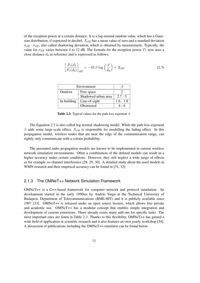
of the reception power at a certain distance. It is a log-normal random value, which has a Gaus-sian distribution, if expressed in decibel. XdB has a mean value of zero and a standard deviationσdB · σdB , also called shadowing deviation, which is obtained by measurement. Typically, thevalue for σdB varies between 4 to 12 dB. The formula for the reception power Pr now uses aclose distance d0 as reference and is expressed as follows:
[Pr(d)Pr(d0)
]dB
= −10β log(d
d0
)+XdB (2.3)
Environment β
Outdoor Free space 2Shadowed urban area 2.7 - 5
In building Line-of-sight 1.6 - 1.8Obstructed 4 - 6
Table 2.2: Typical values for the path loss exponent β.
The Equation 2.3 is also called log-normal shadowing model. While the path loss exponentβ adds some large-scale effect, XdB is responsible for modelling the fading effect. In thispropagation model, wireless nodes that are near the edge of the communication range, canrightly only communicate with a certain probability.
The presented radio propagation models are known to be implemented in current wirelessnetwork simulation environments. Often a combination of the defined models can result in ahigher accuracy under certain conditions. However, they still neglect a wide range of effectsas for example co-channel interference [28, 29, 30]. A detailed study about the used models inWMN research and their empirical accuracy can be found in [31, 32].
2.1.3 The OMNeT++ Network Simulation Framework
OMNeT++ is a C++-based framework for computer network and protocol simulation. Itsdevelopment started in the early 1990ies by Andras Varga at the Technical University ofBudapest, Department of Telecommunications (BME-HIT) and it is publicly available since1997 [33]. OMNeT++ is released under an open source license, which allows free privateand academic use. OMNeT++ has a modular concept that enables simple integration anddevelopment of custom extensions. There already exists many add-ons for specific tasks. Themost important ones are listen in Table 2.3. Thanks to this flexibility, OMNeT++ has gained awide field of application in scientific research and it also features an own yearly workshop [34].A discussion of publications including the OMNeT++ simulator can be found below.
11

Project Implemented ExtensionsINET Internet protocols such as UDP, TCP, SCTP, IP, IPv6, Ethernet, PPP, IEEE
802.11, MPLS, OSPF, etc.MiXiM Wireless and mobile simulations (IEEE 802.15.4, etc.)Oversim Peer-to-peer and overlay networksxMIPv6 Mobile IPv6 protocolCastalia Wireless Sensor Networks (WSN) and generally networks of lowpower em-
bedded devices
Table 2.3: Most important add-ons for the OMNeT++ simulation framework.
OMNeT++ Internals
OMNeT++ is a discrete event network simulator. It consists of a main library for the simulationcore and a module framework to build a network architecture or protocol. The interaction ofthe network components is modelled by passing messages between the modules. The basic OM-NeT++ distribution already contains a big number of predefined modules, which are built on twogeneric module types. One type is the simple module. It contains the message handling logic,e.g., part of a network adaptor or a protocol stack. The other type is the compound module.It combines several simple modules or other compound modules to higher order entities, e.g.,network adapters, hosts or even full networks (Figure 2.1). The modules are connected throughmessage queues on module gates, which handle the messages exchange inside the simulation.Properties such as data rate, propagation delay, and bit error rate can be added to a messagequeue. The object-oriented inheritance system provides an easy integration of new moduleswith adapted behaviour or properties. While the simple modules are proper C++ classes inherit-ing from the simulation library’s cModule, the compound modules are defined in a NED file. Itlists the combined simple modules and connects their message gates. The NED language is anOMNeT++ specific topology description language. It supports the concept of packages to dis-tinguish name spaces, inheritance, dynamical number of modules and property value assignmentinside modules. An additional advantage is the ability to convert these NED files from and toXML files without losing any information. This makes it viable for programmatic manipulationand generation of the NED files with information stored in other systems, e.g., an SQL database.More details about the concrete implementation of the OMNeT++ simulation environment canbe found in the author’s paper about this topic [33].
An important feature of OMNeT++ is the rich graphical user interface (GUI), built on Toolkit(Tk) widgets [35]. It allows starting pre-configured simulation runs, shows a graphical repre-sentation of the full simulation setup and offers a detailed browser for module introspection,debugging, and analysing logged simulation results. This is also supported for any user writtenmodules. The OMNeT++ framework provides special variables and data containers for state andperformance tracking and logging.
12

Network Simple modules
Gates
Figure 2.1: Module structure in OMNeT++.
OMNeT++ in WMN Research
There are a lot of publications evaluating the wireless capabilities of OMNeT++ and itsextensions. The authors of [36] have compared the wireless network performance of a realIEEE 802.11g network with an OMNeT++ simulation. They attest a high model accuracy inmost cases, especially for long observation periods, but also note some inaccuracies in case ofrare events. Another performance evaluation of OMNeT++ investigates the hand-over time ofa wireless station moving between two access points [37]. The paper eventually concludes thatthe simulation measurement conforms the expected theoretical values but, “In order to obtaina handover delay that accurately follows real implementations, cross talk between channelsmust be modelled”. A detailed investigation of different radio propagation models implementedwith the OMNeT++ Mobility Framework add-on has been made in [38]. Additionally to thedeterministic Free Space Model, a probabilistic model with a shadowing effect based on theNakagami distribution has been implemented and compared with the ns-2 network simulator.In [39], different interference scenarios with help of OMNeT++ and the INET frameworkhave been evaluated. For this reason, real traffic has been recorded from an existing locationand combined with the virtual traffic of the simulation scenario, to compute the resultinginterferences. With the help of such a technique it is possible to add a specific location-basedinterference model to the INET wireless model.
The modular design of OMNeT++ is well suited for VirtualMesh. Thanks to its clear in-terfaces and module structure, the required functionality can be fully integrated. Also the sim-ulation scheduler itself is pluggable and can be easily exchanged. Furthermore, the integratedwireless stack has been evaluated and used by many research projects what guarantees a solidbase when using these components for VirtualMesh. The listed add-on frameworks for OM-NeT++ (Table 2.3) aditionally offer a number of alternative link-layer protocols for future en-hancements of VirtualMesh.
13

2.2 Network Emulation
Network simulations have been introduced in Section 2.1 as a common instrument to studycomplex network scenarios as they happen in a WMN. Still this approach suffers from the dis-advantage that the entire system needs to be implemented inside the simulation. While this canbe appropriate for the study of protocols under laboratory conditions, the understanding of aWMN should not be limited to the protocol behaviour. In VirtualMesh, we are interested in run-ning the original OS software stack in a WMN. The network and transport protocols are alreadyfully implemented in the OS kernel and so only the medium access and the wireless propagationremain to be modelled. This is achieved by a wireless network emulation.
2.2.1 Emulation Basics
Emulation is a technique to provide the interface and functionality of a system component ina potentially unrelated environment. In the best case the emulation offers the same functionalproperties (service) and the same non-functional properties (performance) as the original sys-tem. Since an emulation imitates the interface of the real system that it models, it can be usedtransparently without requiring changes on other parts of the setup. The decision which ele-ments are in the form of real devices or software and which parts are modelled depends on thepurpose and study goal of the emulation. The experience with emulation has grown with thedevelopment of new chip designs, where the functionality has been first modelled in softwarefor examination. Another wide-spread application is the use of processor emulation for portingsoftware to unavailable hardware architectures.
In computer network research, emulation can be used as an instrument to model the func-tionality and properties of a network link, such as connectivity, latency and bandwidth capacity.It still allows running the original protocols and applications of a real OS. This makes networkemulation a valuable technique to study realistic network scenarios. The authors of [40] pro-vide a detailed discussion about this topic. They mainly name four major application areas fornetwork emulation:
• Study the behaviour of a protocol implementation under specific network conditions tofind outside effects, limitations, bugs, or any problems.
• Comparison of different protocols under the same network and traffic conditions to studythe advantages and drawbacks of the individual solutions.
• Testing and benchmarking protocols and applications for evaluation purpose.
• Demonstration of the effectiveness of distributed network applications in a realistic net-work scenario.
These applications are congruent with our motivations for VirtualMesh made in Section 1.4, thusnetwork emulation has been selected as the basic principle for our solution.
14

2.2.2 Simulation Requirements for Real-Time Emulation
The structured and flexible architecture of a network simulation is an ideal instrument for mod-elling the wireless link properties. Still, it has to satisfy a number of non-trivial requirements tointegrate the simulation with the real environment and to guarantee the accuracy of the expectedresults. These are:
(a) Interface to connect the real network hosts to the simulator (‘host-in-the-loop’).(b) Compatible protocol stack emulation.(c) Simulation time synchronised with real time.(d) Realistic physical environmental effects.
In the following, these requirements are discussed in more detail.
(a) ‘Host-in-the-loop’ Interface
A mechanism is required to integrate the real-world application traffic into the network simula-tion. The complexity of this interface is depending on the network layer, on which the emulationis performed. Every real network packet arriving at the simulation model has to be translatedinto a simulation internal packet representation, which can be handled by the simulation. Higherlayer protocols, such as transport or sophisticated application layer protocols, are much moredifficult to transform due to their extensive state models and their overall complexity. Lowerlayer protocols, such as medium access or link-layer protocols, are more trivial to handle sincethey are mostly only datagram protocols, which can be parsed with less effort. This interfaceneeds to be transparent to the network hosts.
(b) Compatible Protocol Stack Emulation
Once the a network packet is represented in the simulation, the modelled network stack needsto be compatible to the real behaviour. For example, the simulation environment should notsuddenly ask an Ethernet packet for its target IP address. An Ethernet packet is received basedon the MAC address and therefore has no detailed knowledge about its payload content. In casethe emulation is done on a network or transport layer protocol it has to be ensured, that thebehaviour of the protocol inside the simulation corresponds to the same RFCs or comparableprotocol definitions, as the real implementation. As already mentioned for the ‘host-in-the-loop’interface, this is more complex for higher layer protocols, as they rely on the correct functionalityof a complete network protocol stack.
(c) Synchronization of Simulation Time and Real Time
The most difficult requirement is clearly the synchronisation of simulation time and real clocktime. Normally, a discrete-event network simulator maintains its own representation of time,the simulation time. At every point of time, the pending events are evaluated and executedwithout the consideration of execution time. The progress of simulation time is therefore notcontinuous and heavily depends on the effectiveness of the simulation model. Figure 2.2 shows
15

this behaviour in comparison to real time simulation. The graph of the discrete-event simulationhas no quantitative meaning and may be shifted up or down depending on the performance ofthe simulation.
Sim
ulat
ion
Tim
e
Clock Time
Faster than real-time
Slower than real-time
Real-Time SimulationDescrete-Event Simulation
Figure 2.2: Consideration of clock time vs. simulation time.
If synchronisation with real time is intended, the simulation has to be effective in the execu-tion of events, modelling the connection properties. It should not introduce an unintended packetdelay (Figure 2.3). If a constant event execution time is assumed, the CPU only allows a limitednumber of events to be handled in real-time. In case the simulation generates more events, someof them are consequently delayed. This typically leads to inaccuracies in the packet process-ing. There are two possibilities. First, if the emulation needs to meet hard real-time demands,the events that cannot be processed in real-time have to be dropped and the related packets aredeleted from the system. This behaviour eventually confuses the protocol stack, which leads tounwanted side-effects, such as unnatural packet retransmissions. Hence, in a true real-time em-ulation event dropping has to be avoided by assuring that the hardware performance can alwayscope with the complexity of the simulation. The second possibility is to still deliver the packetwith the introduced delay. In this case, only a soft real-time demand on basis of best-effort canbe met. This procedure has the drawback, that the accuracy of the packet delays is related to thecomputational efficiency of the emulation model, as well as to other external influences. On theother side, it still perfectly models the entire environment for less latency sensitive applications.VirtualMesh is following the approach of soft real-time simulation.
(d) Exact Modelling of Physical Environmental Effects
These effects are depending on the medium that is imitated by the network emulation. In ourstudies about wireless transmission these physical effects are consequently described by a ra-dio propagation model. The common mathematical solutions therefore have been discussed inSection 2.1.2. Detailed interference models can be integrated independently from the physicalenvironment. As they are implemented in software, an accurate repeatability of effects can be
16

Num
ber o
f Sim
ulat
ion
Even
ts
Clock Time
Delayed events
Maximal CPU Events
Figure 2.3: Number of simulation events vs. clock time.
achieved when evaluating series of wireless networking experiments. The difficulty of this re-quirement is the simplification of the environmental effects in a way that they are performant inthe simulation, but still remain representative for a real-world environment.
2.2.3 Emulation-based Wireless Network Evaluation
In scientific research network emulation is a widely used approach to evaluate network protocols,topologies and applications. Also here, at least two different approaches can be distinguished.Some emulation solutions do an on-line processing of live traffic in real-time, as its done inVirtualMesh. The other approach is the off-line processing of previously generated communica-tion scenarios. Depending on the implementation, this is either done by manually defining thescenario, or by capturing live traffic between real-world systems, which is then replayed insidethe emulation environment. The emulation is then either implemented with help of a hardwarecontroller or in software. The software-based approach can even further be distinguished intodedicated network emulator applications and network simulators, which are able to emulate areal network connection by including the real traffic in their environment. In the following sub-sections, we are giving an overview and discuss the different evaluation test-bed approacheswhich are considering network emulation.
Online Network Emulation
Online network emulators provide a solution for this issue. An interesting approach is the useof a hardware-based channel simulator for testing and verifying the wireless network perfor-mance [41, 42]. Real wireless hosts are placed in a radio frequency (RF) shield box and theirradio interfaces are connected to the hardware channel simulator. It is responsible for emulat-ing the signal propagation and interferences using an FPGA (Field-programmable Gate Array)controller. The hardware emulation also supports mobility scenarios and directional antennas.
17

In [42], the IEEE 802.11b performance of a system consisting of 15 nodes has been evalu-ated. The used FPGA supports the modelling of 210 independent channels which also allow theintegration of multipath effects. The advantages of an FPGA-based solution are manifold. Theconsideration of hardware wireless devices using the real medium access (MAC) layer combinedwith a realistic physical layer model, supporting multipath fading, achieves a high accuracy. Fur-thermore, experiments are easily repeatable, as they do not suffer from external interferences.The main drawback is the limited scalability, which depends on the supported number of chan-nels in the channel simulator and the overall hardware costs for an appropriate FPGA.
Offline Network Emulation
W-NINE [43] is a platform aiming at the emulation of a wide range of wireless networks. Ina first stage, a high-level experiment description is processed by an off-line scenario generatorcalled SWINE (Simulator for Wireless Networks Emulation). It computes the network-levelparameters on the IP layer, i.e., data throughput, delay and packet losses, by considering nodemovement, radio propagation issues and communication stack behaviour. In a second step, theirnetwork emulator NINE (Nine Is a Network Emulator) execute the scenario on physical nodesincluding real-world applications. SWINE supports a wide number of radio propagation modelssuch as the free space model, the two-ray model, but also more sophisticated models whichinclude large scale effects like per-obstacle absorption. The authors of the evaluation show ahigh accuracy of wireless related properties. The disadvantage of this solution and generallyoff-line emulators is discussed after the next section.
Another wireless network emulator using a two-stage scenario-driven approach isQOMET [44, 45]. Their main principle is, that in a wireless scenario, network packets eithergo lost or are delayed. They name it ‘quality degradation’. The initial user-generated scenariois therefore transformed into a network quality degradation description, based on a log-distancepath loss model and the IEEE 802.11b specifications. This description can be finally processedwith the Dummynet [46] emulator, which is interconnecting the physical test machines. An eval-uation of QOMET has been done by analysing the wireless communication between a static anda mobile node. Promising results for the packet loss rate, the maximum bandwidth, the averagedelay, the introduced jitter and even some Voice over IP (VOIP) quality tests are given.
Off-line emulators have the advantage that the pre-processing of the behaviour of wirelessconnections can be done without timely pressure. This is valuable for the precise computationof complex effects. The connection properties are afterwards applied to a live system, which usereal-world software for the node communication. In this way the original application stack canbe evaluated. In comparison to on-line emulations, such as VirtualMesh, the off-line emulationtechnique does not allow a modification of wireless parameters based on application feedback,after the scenario has been generated. This makes them unusable to evaluate real-world softwareaccessing and reconfiguring the wireless network interface, as it is possible with VirtualMesh.
Multi-purpose Emulation/Simulation Approaches
There is a lot of effort in trying to show the advantages of emulation-based approaches in com-parison to simulations. An example for such a comparative solution is JiST/MobNet [47]. It
18

provides a flexible Java framework for simulation, emulation and real world testing of wirelessad-hoc networks. MobNet is a wireless extension to the Java in Simulation Time (JiST) li-brary [48]. Their setup allows running the same tests independently of the abstraction level andplatform. The publication mainly evaluates the performance of their solution in respect to softreal-time constraints for event execution and communication mechanisms. They are indicatinga “good scalability of the emulation test-bed up to a few dozen nodes”. The use of Java andthe TUN/pcap (packet capture) APIs are a clear advantage for platform independence. On theother side, the extensive use of Java is also the drawback of this approach. Protocols developedwith JiST first need to be ported to the native network stack, i.e., implementing them in C/C++,before they can be used on a real-world system.
The network experimentation platform Emulab [49] offers an OS independent solutionmainly for local and wide-area network research. An Emulab experiment can consist of sim-ulated, emulated and wide-area links. Connections between real hosts can either be mapped onreal network connections or artificially be modelled with the Dummynet [46] network emulator.The evaluation of the setup has been done by studying the dynamics of different TCP imple-mentations where they could show effects not possible with a pure simulation. Emulab has beenextended for wireless networks in [50]. Several nodes with wireless interfaces are deployed onthe floors of an office building. They are connected to the Emulab network environment andallow an inclusion of wireless experiments. Considering mobility, an interesting approach hasbeen made by mobile Emulab [51]. They extended the Emulab software by a control unit forrobot-based mobile wireless nodes. Thereby, a central, accurate, and repeatable coordination ofthe node movement can be achieved. The communication with the mobile robots is done overan IEEE 802.11b network and 900 MHz radios. Each controllable robot also acts as a wirelessnode. The setup is able to create a fully managed real-world experiment of wireless communi-cation with mobile nodes. The test-bed is based on a commercial robot platform, which shouldallow the replication of the test-bed with modest effort. A main condition for such a test-bedis the availability of a large enough area, what definitely cannot be provided easily. As soon asexperiments are done outdoor, the results are likely disturbed again by external interferences.So, also this setup the downsides mentioned for real-world wireless test-beds can be applied.
The presented solutions combining approaches of simulation, emulation and real-world testsare certainly interesting in the study and comparison of these technologies. The different gran-ularities allows examining effects introduced through the various layers. Still, their main draw-back is the very complex setup. Unfortunately, for these environments are no results availablethat include a wireless model. For such comparative approaches, WMN test-beds are still toocomplex to handle in an accurate way.
Simulation Back-end for Network Emulation
The idea of running a simulator back-end in a wireless network emulation has been previouslyproposed in [52]. The used simulator is the commercial QualNet [53]. The publication includesevaluation results for throughput and video streaming tests in a Linux-based MANET usingthe OLSR [10] routing protocol. This approach has many parallels to VirtualMesh in designand accuracy. Unfortunately, neither the software nor the documentation of QualNet is freelyavailable, so no detailed comparison with VirtualMesh can be made.
19

The most prominent network simulator that can be used for network emulation is ns-2 [54]. Itfeatures a number of sophisticated radio propagation models, and has been widely used for wire-less protocol analysis (e.g., [55, 56]) and the study of physical effects in wireless networks [57].Especially, ns-2 supports a real-time scheduler for network emulation which has been developedin [58]. The authors of [59] evaluate the emulation mode with User-mode Linux instances. Asa main drawback the authors identified that, “[their] current setup imposes some tight limita-tions on the scalability of the simulation complexity”. A more detailed evaluation has been doneby [60]. They compare ns-2 in simulation and emulation mode with a real wireless networksetup. After measuring latency over various hops and packet delivery ratio in all three setupsthey concluded: “The packet delivery ratios and the connectivity graphs can be modelled witha high accuracy once the model is properly calibrated.” They show that their results from theemulated network match the real measurements more accurately than the simulation, since someaspects, such as delays introduced by hardware and the OS, cannot be properly modelled in asimulation.
Recently, the newly developed ns-3 network simulator [61] has been extended to support theintegration of real nodes. They are connected with the simulation through the TUN/TAP driverof the Linux kernel and a proxy node. This allows the evaluation of the protocol stack and nativeapplications under the Linux OS. ns-3 is still very young and therefore no evaluation results havebeen published so far. The traffic redirection techniques used for the network emulation in ns-2,ns-3 and VirtualMesh are quite similar. But as the only solution, VirtualMesh also supports thedynamic modification of the wireless device configuration through the usual system tools whichallows more dynamic test scenarios.
Also OMNeT++ has been previously used for network emulation scenarios. The authorsof [62] evaluate OMNeT++ in a real-time SCTP transport layer emulation. They implementeda simulator interface which is translating real SCTP packets into simulation traffic. The solu-tion is evaluated by measuring the throughput on diverse multi-hop routes, also including puresimulated hosts. Thanks to the restriction to only one protocol it is possible to include hosts,which only exist inside the simulation, as long as the simulated protocol applications understandthe real payload. Their conclusion is that “The major limitation is the CPU of the host runningthe simulation”. In contrast to VirtualMesh, they do not include a wireless model and so theirresults mainly show how efficient SCTP can be parsed from and to the simulation environment.
Even the effort of research in the domain of wireless emulation and evaluation is huge, thereis no other solution available that is fully comparable with VirtualMesh. Many of the presentedefforts still have high hardware costs or lack of an appropriate radio propagation model, protocolindependence, or wireless client configurability.
2.3 Real-world Wireless Network Test-beds
In Section 1.3, real-world test-beds were introduced to be a possible instrument for networkevaluation. At this place, two real-world test-beds used for WMN research are presented andtheir advantages and disadvantages are discussed. Later, ADAM [63], a embedded Linux systemfor wireless mesh networking is introduced. It has been developed by our research lab andextensively used for testing and evaluating WMN technologies in a real-world environment.
20
2.3.1 Examples of Real-world Test-beds
UMIC-Mesh [64] combines several dozens IEEE 802.11a/b/g-based hardware wireless nodeswith virtual hosts running on Xen. The authors of UMIC Mesh have separated the task of wire-less network research into a development and debugging part done in the virtualized environ-ment, and a part including functional and performance evaluation, done within the real test-bed.This solution therefore provides an adapted environment for the different tasks in protocol re-search. However, it has the disadvantage that the overall setup is very complex and expensivein costs and maintenance. Another drawback is the lack of a wireless model in the virtual-ized test-bed. Accordingly, influences of the wireless medium cannot be considered during thedevelopment and debugging cycle of an application.
A similar approach of testing real implementations in a large wireless network is the ORBITtest-bed [65, 66] consisting of four hundred IEEE 802.11 radio nodes. The nodes are built up in aconfigurable indoor radio grid for controlled experimentation and an outdoor field trial wirelessnetwork for evaluating real-world settings. Furthermore, ORBIT provides a sophisticated testingenvironment with a fine-grained measurement framework. The controllable and isolated indoorsetup offers the possibility for detailed studies of wireless interference effects. Although the 20 x20 grid of nodes offers a large variety of different topologies, it can be too restrictive, especiallyregarding mobility tests. ORBIT can be accessed for research by universities, industrial researchlabs, and both US and non-US institutions. The downside of ORBIT are the costly resourcesand the limited access.
OneLab [67] is a European project driven by a number of universities and telecommunica-tion companies. Its target is to develop and provide facilities and tools for computer networkresearch. In the past a few smaller wireless test-beds with about half a dozen nodes have beenused [68]. With OneLab2, an inclusion of larger wireless test-beds is intended [69]. One of itis NITOS (Network Implementation Testbed using Open Source platforms) [70]. It combinesabout fifty wireless nodes of different types (PC Engine Alix2, ORBIT-like nodes) to a Linuxreal-world wireless test-bed. While NITOS is providing static node locations, other associatedtest-beds provide a limited number of laptops for wireless scenarios with mobile nodes.
Evaluations with help of real-world test-beds clearly have the advantage of using real radiotransmission and real computer systems, which allow the study of complex interference effectswith a high fidelity. Nonetheless, in comparison to VirtualMesh, real-world test-beds require anexpensive hardware setup, which need a sophisticated setup for not being influenced by externalradio transmissions. Furthermore, the presented approaches are not flexible at all to conductexperiments including multiple mobile nodes, as it happens in WMNs and MANETs.
2.3.2 ADAM - A Linux Environment for WMN Research
ADAM (Administration and Development of Wireless Mesh Networks) [63, 71, 72] provides aflexible platform for building, configuring, and updating a minimal Linux system, adapted forembedded and wireless mesh networking scenarios.
It includes an build-tool for building an adapted Linux installation. A range of target pro-cessor architectures are supported through different build profiles. They manage the creationof a cross-compilation environment, which allows the building of an ADAM Linux system for
21

a number of embedded platforms, such as Alix (i386) [73], Meraki (mips) [74], and the NeoFreerunner (arm) [75]. Small build scripts arrange the automatic compilation of the applicationsfrom the source code. Afterwards, the integrated image-tool allows the generation of a Linuxsystem image which is then deployed on the wireless nodes. The basic components of a Linuxsystem built with ADAM are listed in Table 2.4.
Program Version Program VersionLinux Kernel 2.6.26.5 µclibc 20080913Busybox 1.11.2 Wireless-tools 29Dropbear sshd 0.51 OpenSSL 0.9.8hradvd 1.2 olsrd 0.5.6cfengine 2.2.8 nostromo httpd 1.9.1
Table 2.4: ADAM mesh node components.
ADAM does not only include the Linux build system, but also provides a user-friendly Webinterface for displaying the node status (Figure 2.4) and for generating and distributing nodeand network configurations for an entire WMN setup. This allows the fast configuration anddeployment of a mesh network. Additionally, an autonomous distribution mechanism integratedin ADAM allows the safe update of the configurations or even the upgrade of an entire operatingsystem image in an already deployed wireless network.
So far ADAM has been used for a number of wireless network publications. [76] evaluateswith help of ADAM wireless nodes multi-path routing inside buildings. [77] uses ADAM-basedwireless nodes in an experimental wide-range communication setup for connecting remote sites.In VirtualMesh, ADAM is used to provide the Linux wireless nodes for the network emulation.
2.4 Operating System Virtualization
In Computer Science, virtualization is defined as technique to abstract and multiplex computerhardware access and CPU time. Nearly every resource is or can be virtualized for better manage-ment. A few examples are virtual memory, virtual networks (VLAN), virtual terminal, virtualmachines for byte-code interpretation (e.g., Java [78] or Common Language Runtime [79]), andalso virtual machines for running entire operating systems. This is called platform virtualizationor also operating system virtualization.
In VirtualMesh we are interested in evaluating a fair number of wireless nodes. With helpof platform virtualization, a single hardware machine is able to concurrently host the operatingsystem instance of every wireless node. Thus, the full operating system functionality, includingthe network and application stack, can be used in VirtualMesh in the same way as on a realhardware machine in a real environment.
2.4.1 Platform Virtualization Overview
Platform virtualization separates the operating system (OS) from the underlying computer re-sources and allows the concurrent use of multiple OS in parallel on the same hardware. In the
22
Figure 2.4: ADAM Web interface of the node status.
1960’s IBM started researching time sharing systems which emerged in the VM/CMS [80] sys-tems in the 1970’s. They first introduced a virtualization solution which allowed the partitioningof the computer hardware between several OS instances. Also other vendors developed similarsolutions afterwards, but as this technology was extremely expensive, it was mainly used in theenterprise segment. Only in the last decade similar features became available on the wide spreadx86 platform. The free User-mode Linux (UML) [81, 82] is an early virtualization technologyused in scientific research for network evaluation [83, 84, 85]. In UML, virtual Linux systemscan run as guest processes on a Linux host machine. The priviledged system instructions of theguest kernel are emulated by the underlying host. Modern approaches implement more efficienttechniques to multiplex virtualized guest systems. The low-level signalling (interrupts) and theaccess to the physical resources such as processor, memory, and I/O-devices are handled by avirtualization management system, which is called Virtual Machine Monitor (VMM) or Hyper-visor. Depending on the implementation, the VMM can run either below the OS directly on thehardware (e.g., VMware ESX [86], Xen [87]) or inside an OS in extension to its kernel (e.g.,Virtualbox [88], KVM [89]).
Another two different techniques for platform virtualization can be distinguished on theirinterface between the VMM and the virtual host. Full virtualization provides an emulation ofthe complete computer hardware (Hardware Virtual Machine, HVM), including I/O devices suchas network and storage controller. In this setup, the guest OS does not notice any difference
23

to a physical computer. It can run completely unmodified as a virtual host, but suffers fromnoticeable performance penalties due to the emulation overhead. Paravirtualization (PV) [90]improves the device access by providing a proprietary driver interface to the virtual machine.The device driver itself is split into a back-end driver in the VMM and a front-end driver in thevirtual host. In that way, the virtual host can achieve nearly native effectiveness.
Any of the presented techniques allow the operation of multiple OS instances sharing thesame physical machine. This significantly reduces the hardware costs for a test-bed and evensimplifies the administration and maintenance of numerous hosts.
2.4.2 Virtualization and Network Evaluation
The already presented test-bed approaches mostly had a common drawback. In case real trafficshould be included, a setup with multiple hardware machines is required. This limits the scala-bility of the test environment and requires more effort for creating and monitoring the test-bedsetup. Platform virtualization is therefore especially useful for network evaluation, as a fair num-ber of network hosts can be handled by a single machine. If a more complex network scenariois required, a network emulation can be connected to imitate the correct network behaviour.
One of the earliest approaches evaluating platform virtualization in MANET research isfound in [91]. It combines L4Linux [92] micro-kernels running as virtual hosts on top of areal-time system. A network emulation is provided by MobiEmu [93], which allows packetforwarding between mobile nodes based on scenario files. Similar to VirtualMesh the traffic iscaptured through virtual network interfaces and then redirected to MobiEmu. In comparison to aprevious approach with User-Mode Linux (UML) [82, 93], the high-performance of the L4Linuxhas been underlined. It allows a test-bed of up to ten Linux nodes on a Pentium 4 with 1.8 GHzand 512 MB memory, versus four with UML. The setup is mainly thought for development andtesting of routing algorithms, since MobiEmu does not support the modelling of communicationerrors and delays of a true wireless scenario.
If real-time behaviour of the emulation cannot be achieved, the domain of virtualizationadds new possibilities of bending the time. The authors of [94] introduce a simple but smarttechnique of manipulating the software timer in Xen for emulating high-speed networks over aslow connection. They have simulated up to a 10 Gbps connection on a physical 100 Mbit link.More sophisticated is the concept of ‘Synchronised Network Emulation’ [95]. It introduces ahybrid setup of platform virtualization with Xen for the node’s representation, and a networkemulation based on OMNeT++. A central synchronisation component controls the run-timebehaviour of both, the simulation and the virtualized systems attached. Thus, they are notdependent on the real-time capability of the simulator. Their evaluation contains successfulping measurements between a simulation node and a virtualization node. The author of [95]even mentioned in a mailing list, that in combination with ns-3 they are able to achieve asynchronisation with an accuracy down to 10 µs [96]. A wireless model is not yet used, so thisis an ideal future extension to the VirtualMesh testing framework. We have already contactedthe authors, but unfortunately, neither the source code for the original paper, nor the ns-3integration has been released so far.
24
Chapter 3
VirtualMesh: An Approach of WirelessNetwork Emulation
VirtualMesh is a framework, which successfully combines established technologies such as com-puter simulation, network emulation and platform virtualization to a comprehensive and flexibledevelopment, debugging, and evaluation platform for WMN and MANET experiments. It al-ready has been published in [97] and [98]. VirtualMesh is able to virtualize the entire test-bedby emulating the wireless network and by running the wireless nodes as fully-featured virtualhosts. The use of Linux hosts as wireless nodes offers the native real-world interface for networkprotocol and application developers. The network scenario that can be used with VirtualMesh isfreely definable and easy to setup in the simulation back-end of the network emulation. Thanksto the flexible approach, VirtualMesh can be adapted to a range of individual study domains.However, our focus is clearly set on IEEE 802.11b network environments.
This chapter introduces the distributed emulation concept of VirtualMesh. In Section 3.1,the general architecture is discussed. Section 3.2 then presents the intermediate communicationprotocol used in VirtualMesh, which has been developed to connect the nodes with the wirelessnetwork simulation. Section 3.3 finally discusses the inclusion of operating system virtualiza-tion, for hosting the wireless nodes in VirtualMesh.
3.1 VirtualMesh Architecture and Design
The basic principle of VirtualMesh is the link layer emulation by a standard network simulator.The simulator is responsible to model the wireless communication including the representationof the wireless device driver, the medium access layer (MAC), and the physical medium, in ourcase the radio transmission. The wireless nodes that can participate in the VirtualMesh wirelessnetwork are native or virtualized Linux hosts. With some restrictions also purely simulatedhosts can be integrated. The Linux nodes do not need to have a wireless card installed as theemulation tools create a virtual wireless interface (VIF) that can be used transparently by theoperating system and applications. Using a custom emulation protocol (Section 3.2), the nodesare connected over a wired infrastructure network to the simulation server which is running thewireless model, the so-called WlanModel. Figure 3.1 shows the division of the network layersbetween the real Linux hosts and the WlanModel. On the nodes, the VIF is forwarding the
25

Internet (ARP, IP and ICMP)
Application
Transport (TCP, UDP, ...)
Wireless Node (Linux Client)
native/virtualized
emulated
Figure 3.1: Subdivision of the TCP/IP networkstack between the wireless node and the wirelesssimulation server.
wireless network traffic to the simulation server and injects the replies back to the local networkstack. As mentioned before, this is done on the data link layer, so VirtualMesh is able to handleall types of network and transport layer protocols implemented in the Linux kernel, includingthe Address Resolution Protocol (ARP) [99].
A network host that wants to participate in the wireless emulation requires a couple of smallutilities, the VirtualMesh client tools, to be installed. They are responsible to create one ormultiple VIF(s) and provide access to the wireless emulation. Furthermore, the tools offer aninterface to manage the wireless driver properties within the simulation model. These clienttools and their implementation are extensively discussed in Chapter 4.
The WlanModel simulation server is connected with all the nodes through the infrastructurenetwork. It receives the forwarded wireless traffic from the nodes and computes the propaga-tion of the packets between the nodes. The WlanModel is implemented and fully integratedin the OMNeT++ network simulator framework [33, 100]. This allows the use of any physi-cal layer technology implemented in OMNeT++ or one of its extensions such as INET [101]or MiXiM [102]. The flexible design enhances the application area of VirtualMesh, which canalso be used for developing and evaluating new radio propagation models for OMNeT++. Perdefault VirtualMesh is using the IEEE 802.11b stack of INET. It is responsible for the correctmodelling of the wireless driver functionality, including the medium access (CSMA/CA) withthe IEEE 802.11 RTS/CTS exchange. By using OMNeT++ VirtualMesh further profits fromthe sophisticated mobility models available for that network simulator. This allows the setup ofextensive mobility scenarios, as they can happen in a MANET or WMN, with minimal effort.The implementation of the WlanModel is discussed in more detail in Chapter 5.
It is also possible to include simple simulation-only wireless nodes, not represented by Linuxnodes. However, the major issue is that they do not have a compatible view of the network and
26

transport layer protocols. As long they do not communicate with real nodes, this issues is nota problem. In this way, simulation-only nodes can be used to generate background traffic forthe wireless emulation. If they also should be used as intermediate hops in a multi-hop com-munication between Linux nodes, the nodes only represented inside the simulation need to beextended to at least correctly handle the ARP protocol, as it is used to find the next-hop desti-nation. Otherwise, the MAC/IP address assignment has to be manually synchronized betweenthe Linux nodes and the simulation-only nodes. For the integration of more sophisticated nodetypes, such as wireless sensor nodes, it has to be ensured that they are able to understand thenetwork or application protocols over which they are accessed from the Linux nodes. One wayto achieve this is to integrate a protocol parser within the node’s simulated network stack, whichthen translates the original Ethernet frames sent by a Linux host to a more specific packet typewhich is understood by the node’s simulated network application. As this is very applicationspecific, such functionality is not yet integrated into VirtualMesh and left for future work.
Figure 3.2 shows the architecture of VirtualMesh. There is a central server hosting theWlanModel and an arbitrary number of real or virtualized Linux nodes. After connecting tothe simulation server, the nodes are represented by a VirtualHost inside the wireless simulation.The infrastructure network is providing the communication channel between the nodes and theWlanModel server. The entire wireless traffic is captured by the VIF, forwarded to the simu-lation server, processed, sent to the target node, and finally received by its VIF. The wirelessnetwork scenario of the WlanModel is completely independent of the physical positions of theparticipating nodes. It can reflect any arbitrary network topology of a WMN and MANET.
Xen Hypervisor
Virtualized Nodes (with virtual wireless devices)
Real Nodes (with virtual wireless devices)
Simulation Server
(WlanModel)
Mesh Routers
Mesh Clients
Communication between Nodes and WlanModel
Figure 3.2: VirtualMesh architecture with virtualized nodes, real nodes and the WlanModel.
VirtualMesh is not able to provide any hard real-time emulation guarantees for the emula-tion. The distributed approach, where the nodes and the simulation server are connected througha normal Ethernet link, is adding a small delay to the wireless connection. It can be minimized
27

by using a high bandwidth link or theoretically even by a low latency interconnection such asInfiniband [103]. Such network installations are not always common in research environmentsand so our experiments are based on a 1 Gbps cross-link. Nonetheless, the wireless packet la-tency is primarily determined by the OMNeT++ simulation model. As the computation of theindividual packet properties may be too computationally intensive to be made in real-time, an-other small delay not found in a real wireless transmission is introduced by the computationoverhead. By using a soft real-time scheduler, described in Section 5.1.1, the WlanModel triesto be as accurate as possible, which is sufficient for most evaluation scenarios. In the evalu-ation part (Section 6.3.3), we examine this delay for our hardware setup and various wirelessemulation conditions in order to estimate how accurate real-time performance evaluations canbe performed.
3.2 Communication Protocol for the Wireless Emulation
The distributed setup of VirtualMesh requires a communication channel and protocol betweenthe wireless nodes and the WlanModel simulation server. Obviously the main purpose is the for-warding of the wireless traffic, but additionally, certain management tasks have to be offered aswell. While the channel is provided by the infrastructure network, the communication protocolis especially developed to meet the specific requirements of VirtualMesh. Though, the followingrequirements are considered.
• Wireless nodes need to be able to join or leave the emulated wireless network and thusinform the simulation model about these actions.
• Each connection need to be identifiable by the simulation model, to which correspondingwireless node it belongs.
• Packet forwarding for exchanging the original wireless traffic must happen with high per-formance and a minimal delay in packet generation and transmission.
• Any arbitrary wireless device parameter, which is changed on the wireless node, has to bepropagated to the simulation server in a timely manner.
• Transparent communication between different processor architectures by ensuring com-patible data representation.
To minimize the complexity of the communication protocol, the management communication(node registration, device configuration change) is unidirectional from the wireless node to thesimulator model. A fully-featured feedback mechanism from the simulation to the node is leftfor future work. Shortly after having considered piggybacking the required information witheach wireless packet forwarded to the simulation, it has been shown, that this approach is notvery performant and too restrictive in its possibilities. Therefore, a simple emulation protocolhas been created. It defines five different packet types for different purposes (see Figure 3.3).As the low-latency behaviour is critical for the wireless traffic exchange, the emulation protocolis put on top of the UDP transport protocol. It is a connection-less datagram protocol that
28

also matches the traffic pattern of the transported wireless frames. UDP does not guarantee thesequence of the packets nor does it guarantee the error-free transmission of the committed data.In VirtualMesh, this can be still accepted, as it is used in a dedicated laboratory environmentonly, where the connectivity between the hosts can be considered optimal. The performancegain of UDP instead of TCP is definitely the determining factor for our choice.
type:register
msg ID
sender ID
hostname
IP/Port v4/v6
numinterfaces
vifname
vifMAC
vifindex
vifproperties
REGISTRATION Message
type:deregister
msg ID
sender ID
DE-REGISTRATION Message
type: ack
msg ID
sender ID
ACK Message
type:data
sender ID
payload size
Ethernet frame
DATA Message
vifindex
CONFIGURATION Message
type:configuration
sender ID
vifindex
vifproperty
property value
Figure 3.3: Protocol messages used to communicate between the wireless nodes and the WlanModel.
3.2.1 Protocol Messages
In this section, the different message types are characterized. The protocol has been imple-mented with a minimal set of functionality in mind, that includes node de-/registration at theWlanModel simulation server, traffic tunnelling between the node and the WlanModel and thepropagation of wireless device parameter changes from the node to the simulation environment.
REGISTRATION Message
The REGISTRATION message is the first message sent by any node that wants to participate inthe wireless emulation. It contains the full information about the node, including a sender iden-tifier, a message identifier, the host name, the connection information (IP address and port) forsending replies, the number of VIFs and the full set of configuration values for the correspond-ing VIFs. Based on this information the simulation server is able to create and initialize theVirtualHost node representation inside the simulation model. The simulated wireless device ofthis VirtualHost then reflects the configuration of the real node and is used to inject the wireless
29

traffic into the simulation network and send its replies from the simulation model back to theoriginal host.
ACK Message
The ACK message is used to acknowledge the registration of the wireless node at the simulationmodel. As long as the node does not receive such a message, it is not able to participate inthe wireless network. The message identifier field corresponds to the message identifier of theacknowledged REGISTRATION message. The sender identification is not used in this message,since it is always the model that acknowledges the messages. It is only present as the ACK andDE-REGISTRATION message share the same packet format.
DE-REGISTRATION Message
The DE-REGISTRATION messages is sent by a wireless node when leaving the wireless emu-lation. It only fills the sender identifier which is compared with the list of registered hosts in thesimulation model. If the initiating node is registered, the corresponding VirtualHost is deletedfrom the simulation network and no further wireless traffic is accepted from or directed to thisnode. The message identifier is unused but present due to format sharing with the ACK message.
DATA Message
The DATA message is used to forward the network traffic from the node to the simulation serverand vice versa. It contains the sender identification, which allows an association of the sendingnode to the corresponding VirtualHost in the simulation model. Furthermore, it includes a fieldto identify the involved VIF, a payload size attribute and eventually the original Ethernet framesent over the VIF to a target wireless node. The payload size is used for sanity checks and easierpayload handling. If the standard Maximal Transmission Unit (MTU) of 1500 bytes has beenset for the VIF, a DATA message containing a full size Ethernet frame cannot fit the same MTUin the infrastructure network. Therefore, it has to be ensured, that either the wireless MTU isconfigured smaller or the MTU of the infrastructure network is big enough to handle a full sizeDATA message without fragmenting the packet.
CONFIGURATION Message
The CONFIGURATION message is sent to inform the simulation model about modificationsof the wireless device properties. It contains the sender identification, to associate the corre-sponding VirtualHost in the simulation model, the involved VIF, the property type, and the newvalue. If a VIF parameter such as transmission power or channel is modified on the wirelessmesh node, the new value is propagated with a CONFIGURATION message to the simulationmodel. Unlike one might expect, the WlanModel does not send an ACK message for a configu-ration change. The acknowledgement of a configuration change has been abandoned in order tominimize the overhead for handling this message in the WlanModel and the client tools. Further-more, it should avoid that the emulation blocks in case no acknowledgement has been received.
30
In the extreme case the parameter change cannot be performed in the WlanModel, the emulationcontinues just with the old value.
3.2.2 Message Flow of the Emulation Protocol
The message flow in the VirtualMesh emulation protocol is simple and straight forward. Thewireless node knows three different protocol states, whereas a state change is always initiatedby the wireless node:
• Unconnected: No connection to the simulation server. Any wireless traffic is dropped.
• Pending registration: A REGISTRATION message has been sent and the node is waitingfor an ACK message.
• Connected: The node is registered at the simulation server. DATA and CONFIGURATIONmessages can be sent any time.
Figure 3.4 shows a typical emulation scenario including two wireless nodes, A and B, and thesimulation server. At the beginning both nodes are in the unconnected state and thus have tosend a REGISTRATION message to the simulation server in order to join the wireless networkemulation. Node A immediately receives an ACK message and is therefore successfullyregistered (1). For some reason, node B does not receive its ACK message (2) and remainsin the state registration pending. It resends a REGISTRATION message after a time-out offive seconds. The second attempt is successful and also node B receives its ACK message.Both nodes are now represented inside the simulation environment and hence in the connectedstate. Now, they are able to send and receive wireless traffic. First, node A sends a wirelesspacket, which is encapsulated in a DATA message directed to the simulation server (3). Insidethe simulation environment, the original packet is decapsulated, processed, and eventuallyencapsulated in a new DATA message, in order to transmit it to the destination node B. Needlessto say, the reply of node B is taking the same way back to node A. In case a wireless deviceparameter is modified, e.g., the nodes are changing the WLAN channel, a correspondingCONFIGURATION message is sent to the simulation model (4). As soon as the nodes wantto leave the wireless emulation, they transmit a DE-REGISTRATION message, the modelthen deletes their representation in the simulation, and the nodes get again in their initial,unconnected state.
3.3 Virtualization in VirtualMesh
VirtualMesh is evaluated in combination with platform virtualization to lower hardware costsand administrative effort. Each virtual node can provide the OS interface (kernel, libraries) ofa real machine and therefore be used to run any kind of real-world application in the wirelessenvironment. The use of a hypervisor running on common x86-compatible hardware is an in-expensive way to provide a sufficient number of wireless nodes for any possible WMN andMANET scenario.
31

connected
connected
ACK
ACK
ACK
Figure 3.4: Message flow between wireless nodes and simulation server.
VirtualMesh is compatible to most of the virtualization products, as long they can host virtualLinux guest systems. For the evaluation of VirtualMesh, we have selected the Xen virtualizationplatform [87]. Xen provides a powerful and efficient open-source stack and is suitably inte-grated into several kernels of free OS such as Linux, NetBSD, FreeBSD or OpenSolaris. It iscurrently regarded as one of the most effective virtualization technologies and widely used inscientific research, especially in combination with network emulation [104, 105, 106]. We haveselected Xen, as it perfectly integrates into VirtualMesh thanks to the full integration of the par-avirtualization feature into the stock Linux kernel. In this way no operational drawbacks needto be accepted when running VirtualMesh in a virtualized environment. Also, Xen is the onlyvirtualization solution which does not require novel CPU virtualization techniques (Intel VT orAMD-V) and thus can be run also on older computer hardware.
The inclusion of operating system virtualization adds a minimal latency overhead for thewireless traffic transmission between the wireless nodes and the simulation server. This effectsare evaluated for our test-bed in Section 6.3.2.
32

Chapter 4
VirtualMesh: Client Implementation
In the previous chapter, the distributed nature of the VirtualMesh framework has been introduced,namely the distinction between the client part on the wireless node, and the server part, whichruns the wireless simulation model. The responsibility of the wireless client is to inform thesimulation which packets have to be sent over the artificial wireless connection and their precisetiming. To achieve the real system’s integration, this is simply done by forwarding the originalnetwork packets to the WlanModel server. This requires a virtual wireless interface (VIF) whereany application can send real traffic to. Furthermore, the client should be able to transparentlyconfigure the properties of its VIF in the same manner, as if it is a real hardware wireless adapter.Ideally, no difference between a native and a virtual wireless device should be experienced.
In this chapter, a closer look is taken on the client part. In Section 4.1 the overall clientarchitecture and design decisions are discussed. Afterwards, the concrete implementation of theclient tools is presented in Section 4.2 (vif-tools) and Section 4.3 (iwconnect). In Section 4.4,the mechanism for propagating the VIF parameter modifications to the simulation model is ex-plained.
4.1 Client Architecture and Design
For a prototype implementation of the client systems, Linux has been selected, as it is a wide-spread OS for embedded systems and research. Additionally, Linux is completely open sourceand its free license allows a straightforward implementation of extensions and modifications.Traditionally, the wireless drivers in the Linux kernel are accessed over the Wireless Exten-sion (WE) API [107]. Also some kernel external wireless driver projects (i.e., Madwifi [108]),support this kernel API. The WE mainly consists of a number of commands, which can be sentover the ioctl device control function of the kernel. User-space tools such as the wireless-toolspackage [109] and wpa supplicant [110] are using the WE API to provide command-line appli-cations for configuring the wireless devices. However, the recent kernel development created anew Netlink-based interface (nl80211 [111]) to access and configure the generic IEEE 802.11functionality, which is shared by some newer wireless drivers. Netlink is a socket-like mecha-nism for IPC between the kernel and the user-space. The appropriate wireless configuration toolusing this new interface is iw [112].
33
Within this mix of technologies in the wireless support of Linux, VirtualMesh has to find anapproach, which provides transparent VIFs to the applications. Moreover, the implementationshould not depend too much on kernel internal structures, since they are in an ongoing devel-opment between different kernel versions. There are different ways how these required func-tionality could be achieved. It is obvious that the kernel needs to provide the network interfaceitself. Only in this way, the networking is transparent to the applications and the kernel-internalnetwork stack is used. But the question remains open, how to provide the artificial wirelessfunctionality and the interface to the simulation model.
One possibility is to develop a dedicated Linux kernel module for the VIF by combining,adapting and enhancing the packet encapsulation functionality of the IP-in-IP tunnel device withthe traditional WE API. Therewith the VIF transparently handles the packet forwarding to themodel and provides the common wireless configuration API to the management applications.Additionally, a user-space application communicating with the kernel (e.g., via Netlink [113] orsysfs [114]) is required to configure the forwarding target (i.e., the simulation server address),The clear advantage of this solution is that all driver related functionality is included in thekernel, where it technically belongs to. As this module provides the same API as a normalwireless device, the user-space configuration tools (e.g., ifconfig, iwconfig) do not have to beadapted to this virtual wireless device. Another big advantage concerning the packet forwardingis, that all performance critical activities reside within the kernel. This could certainly minimisethe packet delay overhead. The disadvantages, however, also have to be considered. Since thismodule is not part of the main kernel source tree any future kernel API change could instantlybreak the compatibility of the module. Furthermore, especially in the domain of embeddedand development systems, where a lot of network testing is done, a likely incompatible kernelversion may be required.
Another approach is to implement as much logic as possible in user-space. This solutiononly depends on the kernel’s TUN [115] device to forward the network traffic to the user-spacewhere it is forwarded to the server. The access to the device configuration can be offered througha shared library that is responsible for managing the internal device state. The obvious disadvan-tage of this approach is the additional overhead introduced through the packet handling outsideof the kernel. This leads to many expensive context switching during a packet transmission.Another shortcoming has to be made at the wireless configuration tool compatibility. Since theVIF is not known to the kernel, the tools have to be enhanced to also query our external virtualwireless device configuration. By imitating the WE ioctl interface, compatibility with the con-figuration tools still can be achieved. As requested, also this solution profits from the standardEthernet interface provided by the TUN kernel driver and guarantees transparent network accessfor the configuration tools and applications.
In favour of the better compatibility and the ease of development, the second approach hasbeen followed and the client tools are completely implemented in user-space. This means thatthe virtual device configuration and redirection part is not that closely tied to the Linux kernel. Itonly requires the TUN device driver, and due to the fact that the tools are written in C, a POSIXcompliant C library. Furthermore, no restrictions on the machine architecture are imposed. Sothese requirements can even be fulfilled by a minimal embedded system. Besides Linux, thepossible target platforms include a number of UNIX-like operating systems including the BSD
34

variants, which are very popular for networking tasks. Since the approach is implemented inuser-space, the development, testing, maintenance, and debugging of the application is morestraightforward than in kernel-space. Moreover, a public API can be provided, so that additionalprograms can easily be adapted or implemented to make use of the VIF. An example of the nec-essary adaptations of an already existing program is shown in Section 4.4.1, where our changesto the Linux wireless-tools package are described.
The VirtualMesh client tools consist of three different binaries. These are the virtual in-terface library libvif, vifctl, and iwconnect. libvif is responsible to abstract the access to theVIF, including its parameter states. It offers an API to access the VIF from existing applica-tions, which allows the management and integration of the virtual wireless device with the usualOS tools. The vifctl utility provided by VirtualMesh makes use of this API and implements acommand-line tool for creating and deleting VIFs. The connection between the wireless nodeand the simulation server is handled by iwconnect, which implements our emulation protocol onthe client side. Figure 4.1 shows the comparison between a real Linux wireless stack and ourVirtualMesh emulation counterpart. With the original stack, the configuration tools (ifconfig,iwconfig) directly access the kernel to modify network and wireless parameters. In VirtualMeshthe network parameters are set in the same way, as they only affect the TUN device of the VIF,provided by the kernel. In this case, the wireless properties are set and retrieved through appli-cations calling libvif. The parameter modifications are then propagated to the network emulationthrough iwconnect.
Wireless device
Linux kernelLinux kernel
Wireless device emulation
VirtualMesh
Wireless node
VirtualMesh
WlanModel
Linux host
with real
wireless
adapter
wireless-tools, net-tools, iproute2 net-tools, iproute2
wireless-tools, vifctl
VirtualMesh emulation protocol
Figure 4.1: Real wireless stack vs. the wireless stack of VirtualMesh.
4.2 vif-Tools
The vif-tools are responsible to provide the virtual wireless device (VIF). They create a networkinterface, which is handled by the client host as a normal wireless network device. The IP
35
address (IPv4 or IPv6), netmask, MTU etc. can be assigned via the normal configuration tools ofLinux, such as ifconfig from the net-tools package [116] or ip from the iproute2 package [117].With a slightly patched version of the wireless-tools it is further possible to set the wirelessparameters, e.g., transmit power, retry limit, wireless frequency. More details about the wireless-tools can be found in Section 4.4.1. Furthermore, there is a mechanism to notify the wirelessdriver representation in the simulation environment about configuration changes done on theclient. This is necessary to ensure that the wireless device on the server operates in the sameway as the VIF device on the client is configured.
In a normal device driver implementation, the kernel address space is used to store the deviceproperties. They are normally read and set by configuration tools, as mentioned above, whichuse the ioctl system call to do so. The Linux wireless drivers using the Wireless ExtensionsAPI (e.g., Madwifi, Prism, Orinocco) and the Ethernet drivers are implemented in such a way.In order to create a compatible VIF in user-space, the vif-tools have been implemented. Theyconsist of two parts:
1. libvif Library for accessing and managing virtual wireless devices2. vifctl Command-line utility to create and delete virtual wireless devices
The virtual interface library libvif is a shared library, that stores the device properties in aglobal address space. They can be accessed and modified through a public API, which imitatesthe wireless extension kernel API. It is used by vifctl to create and delete a VIF, but can alsobe used by other programs to configure the VIF parameters. In the following sections, the twoseparate parts of the vif-tools and their interaction are being discussed in detail.
4.2.1 libvif - Virtual Interface Library
The virtual interface library (libvif ) unifies and controls the access from applications to thevirtual wireless device. It is designed as a shared library, so it is not directly accessed fromthe command line. This is shown in Figure 4.2. Instead of accessing the kernel, the wirelessoperations are performed through libvif. Since the library is only loaded at program run-timeand therefore not constantly in memory, the wireless configuration is stored in a persistentshared memory segment. In case libvif is accessed, the shared memory configuration is loadedand eventually read or modified. libvif has a simple API listed in Table 4.1. It copies the ioctlsystem call from the kernel and adds a number of additional functions for interface creation,listing and removal. libvif has a limited responsibility for the actual wireless emulation. It onlyprovides iwconnect the necessary information about the VIFs for the node registration and thepacket forwarding. Every new application which would like to interact with the configuration ofthe VIF, has to include vif.h and link against libvif to access its functionality. In the following ashort description about each implemented public function is given.
vif init()This function tries to load the shared memory VIF configuration. If there are no VIFspresent at the system a new shared memory segment is initialised. Otherwise the numberof found VIF configurations is returned.
36

Figure 4.2: libvif providing application access to the VIF.
vif init() Load virtual interface configuration listvif get names() List virtual wireless device namesvif create(devname) Create a virtual wireless devicevif delete(devname) Remove virtual wireless devicevif ioctl(type, request) Perform an ioctl() on the virtual devicevif get <property>(devname) Get the value of a wireless property
<property> = mac|channel|frequency|sensitivity|rts|frag|txpower|retry
Table 4.1: Public virtual interface API (defined in vif.h)
vif get names()This call returns the number of virtual devices and their names.
vif create(device name)This function is used to create a VIF. This includes the creation of a TUN device with thegiven name and saving the device’s wireless properties into the shared memory segment.On the creation of a device, its parameters are set to default values based on an Atheroswireless card using the corresponding Madwifi driver. This behaviour could be adapted infuture work for other types of wireless controllers.
vif delete(device name)This function is used to delete the wireless configuration from the shared memory segmentand destroy the corresponding TUN device.
vif ioctl(ioctl type, request)This function emulates the ioctl system call for the VIF. Its arguments are corresponding
37

to the normal system’s ioctl function. They consist of the type of the ioctl and the requeststructure with the device information and parameter fields. The latter is used to set andreturn the wireless device properties. The implemented ioctl types are listed in Table 4.2.Calls, which require operational feedback of the VIF, such as SIOCGIWSTATS forretrieving detailed traffic statistics, are not implemented. To do so, it would be necessaryto query the wireless driver representation in the simulation model. This extension isleft as future work. The nearly complete number of implemented ioctl types offers greatcompatibility with the Linux wireless-tools, e.g., iwconfig (Table 4.3). As the OMNeT++’sIEEE80211NicAdhoc module used in the simulation model cannot handle all of these prop-erties, not all of them really affect the device behaviour in the actual wireless simulation.
SIOCGIWNAME Get the device type (i.e., IEEE 802.11b)SIOCGIWNWID Get the network IDSIOCSIWFREQ Set the radio frequencySIOCGIWFREQ Get the radio frequencySIOCSIWMODE Set the radio mode (i.e., ad-hoc, master, managed)SIOCGIWMODE Get the radio modeSIOCSIWSENS Set the radio sensitivitySIOCGIWSENS Get the radio sensitivitySIOCGIWRANGE Get the driver properties rangeSIOCGIWPRIV Get a list of private ioctl typesSIOCGIWAP Get the access point addressSIOCSIWESSID Set the ESSID nameSIOCGIWESSID Get the ESSID nameSIOCGIWNICKN Get the nicknameSIOCSIWRATE Set the transmission rateSIOCGIWRATE Get the transmission rateSIOCSIWRTS Set the Request-to-Send (RTS) thresholdSIOCGIWRTS Get the Request-to-Send (RTS) thresholdSIOCSIWFRAG Set the fragmentation thresholdSIOCGIWFRAG Get the fragmentation thresholdSIOCSIWTXPOW Set the radio transmission powerSIOCGIWTXPOW Get the radio transmission powerSIOCSIWRETRY Set the number of retriesSIOCGIWRETRY Get the number of retriesSIOCSIWENCODE Set the encryption key/propertiesSIOCGIWENCODE Get the encryption key/propertiesSIOCGIWPOWER Get the power management properties
Table 4.2: Supported ioctl types by libvif
38

vif get <property>(device name)Returns a property value of the given wireless device. This is mainly used to get the newvalue after a configuration change. The <property> can be one of the following: MACaddress, channel, frequency, fragmentation threshold, retry limit, RTS threshold, radio sen-sitivity, or transmission power. The corresponding functions are named accordingly (e.g.,vif get channel()).
4.2.2 vifctl - Virtual Interface Control
vifctl is a minimal command-line front-end to libvif, which is able to create and delete virtualwireless interfaces (VIF). Its name refers to similar Linux networking tools like brctl, which isused to combine interfaces in a bridge, or tunctl, for managing TUN/TAP devices. The userinterface of vifctl is shown in Listing 4.1.root@node01:˜ # vifctl -hUsage: vifctl [-cdhlr] VIFNAME
Create/delete virtual wireless interfacesArguments: -c VIFNAME Create virtual wireless interface
-r VIFNAME Remove virtual wireless interface-l List virtual wireless interfaces-d Enable verbose output-h Print this help
Listing 4.1: vifctl user interface.
To create a virtual interface, vifctl has to be invoked with the ’-c’ argument and the desireddevice name. After checking for duplicate names, vifctl calls the vif create() function pro-vided by libvif, which does the setup and initialization tasks of the VIF as described above. Thisoperation actually imitates the loading of a wireless device module into the kernel, where thecorresponding device, e.g., ath0 is created. After creating the VIF, it can be configured in thesame way, as a normal network interface. To modify the wireless parameters of the VIF, anadapted version of the wireless-tools is used (see Section 4.4.1). In order to send and receiveemulated wireless traffic, the node first has to be registered at the WlanModel by invoking iw-connect. A VIF can be deleted again by running vifctl with the ’-r’ argument or by restarting thewireless node. As for a real network device, it is not possible to save the device configurationover a reboot of the OS. However, the VIF can be automatically initialised at system start-up viathe common network configuration scripts. Listing 4.2 is showing an example configuration fora VIF in a Debian-based Linux distribution.auto v_ath0iface v_ath0 inet static
pre-up vifctl -c v_ath0address 192.168.1.1netmask 255.255.255.0wireless_mode ad-hocwireless_channel 8wireless_essid virtualmeshpost-down vifctl -r v_ath0
Listing 4.2: VIF configuration in /etc/network/interfaces.
39

4.3 iwconnect
The iwconnect utility is a system service that connects the wireless node to the simulation model.Its main responsibility is the forwarding of the wireless traffic from the VIF to the wireless modeland the re-injection of the received traffic from the model into the local network stack. iwconnectalso handles the node registration and the propagation of wireless configuration changes to theWlanModel.
The user interface of iwconnect is shown in Listing 4.3. It requires to specify the simulationserver host to which the traffic has to be forwarded. Optionally, the infrastructure networkdevice for the communication with the model server can be selected. This is especially usefulfor hosts, with multiple network interfaces in different networks. If it is not specified, the trafficis forwarded using the default interface eth0. If the infrastructure network supports IPv6, thereis also an argument to force communication over IPv6. If debugging is enabled, every packet isprinted to the command line with its properties and its content.root@node01:˜ # iwconnect -hUsage: iwconnect WLANMODEL [-p PORT][-i INTERFACE][-6][-n][-d][-h]
Iwconnect tunnels traffic from a virtual wireless interfaceto a wireless emulation model. First you have to create a virtualinterface with ‘vifctl -c INTERFACE‘. The virtual interfaces arethen detected automatically by iwconnect.
Parameters:WLANMODEL IP address/hostname of the wireless simulation model-p PORT Destination port (default: 2424)-i INTERFACE Infrastructure network interface (default: eth0)-6 Use IPv6 protocol-d Enable debug output-n Enable node-to-node communication without registration
(only for testing!)-h Show this help message
Listing 4.3: iwconnect user interface.
On program start iwconnect queries libvif to learn about the virtual wireless devices. Everydevice which has been created with vifctl is considered and enabled for wireless traffic emu-lation via WlanModel. If there are multiple virtual devices, all of them are represented withinthe same wireless model server. For the interaction with the WlanModel simulation server theemulation protocol described in Section 3.2 is used. The program start immediately triggers aREGISTRATION message to be sent to the simulation server. This can be prevented by addingthe ’-n’ argument when invoking iwconnect. In this way, it is possible to directly tunnel the traf-fic between two wireless clients without emulating the wireless propagation connectivity. Thisis especially useful for debugging and benchmarking the iwconnect utility. For example, wehave analysed the latency introduced through iwconnect in our evaluation part in Section 6.3.2.When the wireless node is successfully registered at the simulation model, iwconnect receivesthe Ethernet frames from the VIF and encapsulates them into DATA messages, which then aresent to the simulation server. At the same time it listens on UDP port 2424 for reply packets sentby the server. In case a wireless parameter in libvif is changed, iwconnect is informed about
40

this action and triggers a CONFIGURATION message with the updated values. This mechanismis described in more detail in Section 4.4.2. If the wireless node wants to leave the wirelessnetwork it has to shut down iwconnect. This is done by sending a SIGTERM signal to the run-ning iwconnect daemon, e.g. by invoking ‘kill -15 `pidof iwconnect`’ on the command-line. ADE-REGISTRATOIN message is then sent and the traffic forwarding from the VIF is stopped.
4.4 Virtual Interface Configuration
The previous section has presented vifctl as the tool to create a virtual device and initialises itwith the default wireless properties. It does not provide access to directly set or change thewireless parameters. For compatibility to the configuration procedure of a real wireless devicethis is done with the usual OS tools. But since the VIF is not registered in the kernel as a wirelessdevice, these tools need to be modified to use libvif, as shown in Figure 4.2. In this section therequirent changes are described, which are necessary to integrate libvif in a custom application.Later on, the configuration change propagation via iwconnect to the model is explained.
4.4.1 Linux Wireless Tools
As mentioned earlier, Linux wireless drivers using the wireless extension (WE) are normallyconfigured through the wireless-tools. For the VirtualMesh framework, they are adapted to alsoconsider our VIFs, thorugh libvif. libvif is designed to support the same syntax as the originalioctl system calls, so the amount of required modification is minimised. Listing 4.4 shows thepatch for iwlib.h, which adds libvif support to the wireless-tools utilities. The only requiredmodification is calling vif ioctl() if the kernel’s ioctl call fails. This means if the name of awireless interface (i.e., the name of the VIF) is not known to the kernel, the operation is handledby libvif.
--- wireless_tools.29/iwlib.h 2007-06-22 20:01:04.000000000 +0200+++ wireless-tools-libvif/iwlib.h 2009-07-13 13:39:31.000000000 +0200@@ -282,6 +282,9 @@+ /∗ ∗∗∗∗∗∗∗∗∗∗∗∗∗∗∗∗∗∗∗∗∗∗∗∗∗∗∗ VIF SUPPORT ∗∗∗∗∗∗∗∗∗∗∗∗∗∗∗∗∗∗∗∗∗∗∗∗∗∗ ∗ /+#include <vif.h>+
@@ -508,10 +511,16 @@+ int rtrn;+
/∗ S e t d e v i c e name ∗ /strncpy(pwrq->ifr_name, ifname, IFNAMSIZ);/∗ Do t h e r e q u e s t ∗ /
- return(ioctl(skfd, request, pwrq));++ if((rtrn = ioctl(skfd, request, pwrq)) < 0)+ rtrn = vif_ioctl(request, pwrq);++ return(rtrn);
Listing 4.4: Modifications to the standard wireless-tools library (iwlib) in order to add libvif support
41
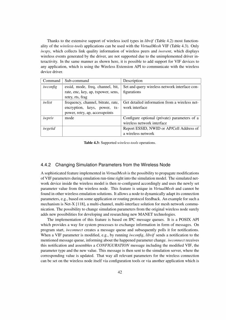
Thanks to the extensive support of wireless ioctl types in libvif (Table 4.2) most function-ality of the wireless-tools applications can be used with the VirtualMesh VIF (Table 4.3). Onlyiwspy, which collects link quality information of wireless peers and iwevent, which displayswireless events generated by the driver, are not supported due to the unimplemented driver in-teractivity. In the same manner as shown here, it is possible to add support for VIF devices toany application, which is using the Wireless Extension API to communicate with the wirelessdevice driver.
Command Sub-command Descriptioniwconfig essid, mode, freq, channel, bit,
rate, enc, key, ap, txpower, sens,retry, rts, frag
Set and query wireless network interface con-figurations
iwlist frequency, channel, bitrate, rate,encryption, keys, power, tx-power, retry, ap, accesspoints
Get detailed information from a wireless net-work interface
iwpriv mode Configure optional (private) parameters of awireless network interface
iwgetid Report ESSID, NWID or AP/Cell Address ofa wireless network
Table 4.3: Supported wireless-tools operations.
4.4.2 Changing Simulation Parameters from the Wireless Node
A sophisticated feature implemented in VirtualMesh is the possibility to propagate modificationsof VIF parameters during emulation run-time right into the simulation model. The simulated net-work device inside the wireless model is then re-configured accordingly and uses the newly setparameter value from the wireless node. This feature is unique in VirtualMesh and cannot befound in other wireless emulation solutions. It allows a node to dynamically adapt its connectionparameters, e.g., based on some application or routing protocol feedback. An example for such amechanism is Net-X [118], a multi-channel, multi-interface solution for mesh network commu-nication. The possibility to change simulation parameters from the original wireless node surelyadds new possibilities for developing and researching new MANET technologies.
The implementation of this feature is based on IPC message queues. It is a POSIX APIwhich provides a way for system processes to exchange information in form of messages. Onprogram start, iwconnect creates a message queue and subsequently polls it for notifications.When a VIF parameter is modified, e.g., by running iwconfig, libvif sends a notification to thementioned message queue, informing about the happened parameter change. iwconnect receivesthis notification and assembles a CONFIGURATION message including the modified VIF, theparameter type and the new value. This message is then sent to the simulation server, where thecorresponding value is updated. That way all relevant parameters for the wireless connectioncan be set on the wireless node itself via configuration tools or via another application which is
42

accessing libvif.This notification mechanism can be extended to also handle other information with addi-
tional message types. It provides a basis for sending arbitrary data from the wireless node tothe simulation environment. This could include the dynamic addition or removal of wirelessdevices, or notifications about the power management, which could then be reflected in the sim-ulation environment. So far the notification only works in one direction. From the wireless nodeto the wireless model. A bi-directional mechanism is clearly more complex and an interestingidea for future work.
43


Chapter 5
VirtualMesh: Wireless Simulation Server
The simulation server, called WlanModel, is the central part of the VirtualMesh wireless networkemulation architecture. It receives the original link layer traffic from the wireless nodes and isresponsible to model the wireless connection properties. Based on a real-time simulation, thereceived network packets are temporarily accurately forwarded to the other connected wirelessnodes that are within reception range. The WlanModel simulation is based on the OMNeT++network simulation framework [100]. To compute the packet delay and node connectivity itfurther utilizes the IEEE 802.11b implementation of the INET simulation framework [101]. Ithas been extended to represent our wireless nodes inside the simulation environment. The con-figuration of the simulated wireless device is thereby reflecting the VIF settings of the involvedwireless nodes. The simulated hosts then inject the wireless traffic forwarded by their corre-sponding node’s iwconnect tool into the wireless simulation. The position of the nodes withinthe simulated playground area can be freely configured, with support of many advanced mobilitymodels provided by INET.
In this chapter, the implementation of the WlanModel is discussed. First, section 5.1 gives anoverview about the individual OMNeT++ modules and components involved in the WlanModel.Later, in Section 5.2, the focuse is then set on the functionality of WlanModel, where the messageflow between these modules is evaluated.
5.1 WlanModel Components
The WlanModel has been implemented around the fully-featured simulation library of the OM-NeT++ simulation framework. It intensively uses the offered features such as the module system,which also includes the NED file parser. WlanModel further adds its own real-time scheduler(EmulationRTScheduler) to the simulation core and builds up a dynamic wireless network sim-ulation based on internally developed modules and some extensions of INET.
Figure 5.1 shows an overview of the modules used in WlanModel. Our custom modules,namely ProtocolHandler, NodeManager, VirtualHost and VifBackend enable the integration ofexternal wireless nodes into the simulation model. On the other side, additional INET mod-ules are responsible for providing the IEEE 802.11b network stack (IEEE80211NicAdhoc), aswell as the radio propagation model driven by ChannelControl, and various mobility models.
45

WlanModel is able to run with the detailed graphical user interface (Tkenv), which can be usedfor analysing and debugging. However, the graphical interface adds a big delay to the messageprocessing, so it should not be considered when running a performance critical wireless emula-tion experiment. As a consequence, WlanModel employs the alternative command line interface(Cmdenv), which minimizes the feedback to the user and thus reduces the packet processingdelay.
OMNeT++Simulation Kernel
EmulationRTScheduler
INET Library
- IEEE80211NicAdhoc
- ChannelControl
- Mobility
Figure 5.1: WlanModel components.
Our implementation is based on OMNeT++ version 4.0, released in March 2009. The codealso should remain compatible to any later 4.x releases. Subsequently, the single components ofWlanModel are discussed.
5.1.1 EmulationRTScheduler
The communication between the OMNeT++ simulation modules works via messages which arecoordinated by the simulation scheduler. These messages define events representing the net-works functionality (e.g. send a packet to a host, handle a packet to a higher protocol layer),which are executed when the message is scheduled. OMNeT++ admits the inclusion of a cus-tom scheduler. Hence, a custom soft real-time scheduler has been developped to provide therequired functionality for WlanModel. Additionally, to the internal messages, our schedulerfurther considers external traffic received from the wireless nodes. As a consequence the Emu-lationRTScheduler listens on the UDP socket 2424 for arriving network packets. These packetstrigger new messages, which are added to the simulation queue and therefore are consideredin the scheduling. This dependency on real-time events, which require immediate attendance,classify the scheduler as a real-time scheduler. Also, the messages are scheduled relating to theclock time instead of an independent simulation time. This results in message delays in case thecomputational effort is too high for real-time execution. Also the design of the scheduler itselfadds some temporal restrictions, so it is not capable to meet hard real-time demands. Therefore,
46

the EmulationRTScheduler is classified as a soft real-time scheduler.The implemented scheduling policy is as follows (Figure 5.2): Each message generated by
a module or an arriving network packet is added to a global message queue, with an event timestamp (ET). This ET tells the scheduler when the message needs to be scheduled to accuratelymodel the network’s behaviour. The scheduler now checks the queue and if there are nomessages in the queue or the first message’s ET is still in the future, the scheduler is listeningon the network socket for further arriving packets. This is done by monitoring the network filedescriptor for a SIGIO signal, which indicates that it has received some data. If this happens, anotification message is immediately sent to the ProtocolHandler module, which then takes overthe responsibility of the packet. If no network packet is received within the given time-out, thescheduler checks the message queue again and the algorithm goes to the next iteration.
check scheduler queue for event messages
check event time (ET)
[found event message]
listen on network sockettill timeout expires
set timeout
[no event message]
[ET > current time]
send event message(execute event)
[ET =< current time][no packet received]
create event message for incoming packet
[receive packet]
Figure 5.2: EmulationRTScheduler state diagram.
The used approach has the following caveats. First, there is only one global message queue.Therefore, all internal messages have the same priority. This can result in event messages,generated by the reception of a REGISTRATION or CONFIGURATION message, slowing downthe processing of DATA messages. Fortunately, the occurrence of such interrupting messages isvery small compared to the amount of DATA messages.
Second, the global message queue is meant to be chronological. Each new message is sup-posed to have an ET later than the previous one. This could result in a wireless message, whosecomputed transmission latency sets the arrival time at the destination node in a few microsecondsin the future. The corresponding simulation message representing the arrival event therefore hasan et in the future. The scheduler therefore ignores the message and listens on the network
47

socket for new packets, until the point in time is reached to appropriately execute the mentionedpacket arrival. In this meantime, an external network packet is received. The ET for furtherprocessing the new network packet is obviously its arrival time and therefore still smaller thanthe ET of the wireless message. Nonetheless, it is enqueued after the latter. Accordingly, thescheduler first needs to wait for the ET of the wireless packet to arrive, before it can schedulethe further computation of the arrived network packet.
The third caveat can be concluded by the just described scenario. The internal messagequeue is prioritised over the network socket. If there are still messages in the scheduler queuewith an expired ET, they are first processed before new network packets are received. Thisensures that the system does not overload with messages, which could starve in the messagequeue. As long there are messages with the current ET, new network packets arriving from thenodes are ignored. This behaviour can add a slight delay to incoming packets, if the system isvery busy. However, this delay is so small, that it does not influence the overall behaviour of thewireless emulation.
5.1.2 ProtocolHandler
The ProtocolHandler module is responsible to handle the communication protocol (Section 3.2)with the wireless node. Depending on the message type, it can be REGISTRATION, DE-REGISTRATION, CONFIGURATION, or DATA, the ProtocolHandler forwards the informationto the NodeManager or a VirtualHost within the simulation. In case of a faulty message type,the message is discarded.
5.1.3 NodeManager
The NodeManager module keeps track of the participating wireless nodes in the simulation.They register and de-register themselves dynamically through iwconnect (Section 4.3). On reg-istration the NodeManager creates a new VirtualHost module which represents the wireless nodehenceforth. The module is deleted as soon as the node has de-registered.
5.1.4 VirtualHost
The VirtualHost is a compound module consisting of the VifBackend, the IEEE80211NicAdhocand several INET simple modules required for correct functionality. It is the virtual represen-tation of a wireless node within the simulation. For identification it stores the wireless node’sparameters such as host name, host ID, and host address sent with the REGISTRATION mes-sage. Among the included INET modules is a mobility module, which keeps track of the node’scurrent position. It is fully integrated into the INET’s mobility framework, which allows theconfiguration of various mobility patterns. Per default the NullMobility module is used to set thenode to a static position.
48

5.1.5 VifBackend
The VifBackend is the interface to the simulated network device. The main purpose is to handlethe communication between the the wireless node and the virtual wireless interface representedthrough IEEE80211NicAdhoc in the simulation. If the VifBackend receives a DATA message,it extracts the original Ethernet frame and creates a RAWEtherFrame packet within the simu-lation. It also handles the received RAWEtherFrames from the wireless device and sends themas DATA messages back to the wireless node. Additionally, the VifBackend offers an interfaceto change the wireless parameters in the IEEE80211NicAdhoc, which is used for handling theCONFIGURATION messages.
5.1.6 RAWEtherFrame
Unlike some other network emulation simulation scenarios in OMNeT++ (e.g., [62]), the orig-inal network packets are not parsed and wrapped into their specific protocol. VirtualMesh isworking on link layer (Figure 3.1) and therefore only uses a simple Ethernet frame simulationpacket. This is RAWEtherFrame, which simply wraps the original Ethernet frame within thesimulation. RAWEtherFrame is an enhanced version of INET’s EtherFrame and so it can behandled by any INET network device module. On creation, it autonomously fills in its destina-tion MAC address, as well as the packet size according to the original frame, which is stored inthe payload. The transformation from and into a RAWEtherFrame can only be performed by theVirtualHost and does not allow communication between real wireless nodes and simulation-onlywireless hosts. Message parsing for supporting these interactions is left for future work.
5.1.7 IEEE80211NicAdhoc
The IEEE80211NicAdhoc is an INET module that implements an IEEE 802.11 wireless networkadapter in ad-hoc mode. It is a compound module that contains of the following simple modules:
IEEE80211MgmtAdhoc It represents the module for managing the wireless network de-vice. It supports channel switching. The INET version correctlyhandles IEEE 802.11 data frames, but no control or managementframes.
IEEE80211Mac This module implements the MAC layer. It receives data andmanagement frames from the upper layer, and transmits themaccording to the CSMA/CA protocol.
IEEE80211Radio This module implements the physical layer. It deals with mod-elling transmission and reception of wireless frames. For a moredetailed description please see Section 5.1.8. There are imple-mentations with alternative reception models available. Thereis the SnrEval80211 developed in [38] or the Decider80211 im-plementing a Gilbert Elliot bit error model [119].
49

This IEEE80211NicAdhoc network adaptor module is able to join a wireless network in ad-hoc mode, as it is often used for setting up WMNs with commodity hardware. Especially, it alsosupports channel switching during the simulation.
5.1.8 IEEE80211Radio
This module is responsible for transmitting and receiving wireless frames. It implements theAbstractRadio interface which allows to separately define a radio and a reception model. Theradio model defined in IEEE80211RadioModel is responsible for calculating frame duration,and modelling the modulation scheme and possible forward error correction. The receptionmodel defined in PathLossReceptionModel is responsible for modelling path loss, interferenceand antenna gain. It implements the free space radio propagation model covered in Section 2.1.2with an additional path loss α. The reception power Pr is computed by Equation 5.1, which isderived from the Friis Equation 2.1. The used wave length λ is defined in Equation 5.2.
Pr =λ2 Pt
(4π)2 dα(5.1)
λ = wave length Pt = transmission powerα = path loss coefficient d = transmission distance
λ =c
fc(5.2)
c = speed of light fc = carrier frequency
The IEEE80211Radio module supports a wide range of configuration parameters. These param-eters include channel number, transmission power, bit rate, thermal noise, signal-to-noise ratio,sensitivity and the path loss exponent.
5.1.9 ChannelControl
The ChannelControl module, which is also part of the INET framework, is the central compo-nent of the wireless network model. It gets informed about the location and movement of thewireless nodes, and determines which nodes are within communication distance. There are var-ious parameters, which need to be known by ChannelControl: the playground dimensions, themaximum sending power used for this network, the signal attenuation threshold, the path losscoefficient, the basic carrier frequency and the number of available wireless channels.
All wireless nodes which are within a so-called interference distance di from the trans-mitting node, are considered to receive a packet. The interference distance is calculated withEquation 5.1 resolved by distance using the pre-defined maximal transmission power Ptmax andminimal reception power Prmin , which is derived from the signal attenuation threshold. Eachnode within this range receives a transmitted frame and decides individually if it accepts theframe or discards it due to noise or bit errors. In this way the overhead of participating nodesoutside the transmission range is minimised.
50

ChannelControl supports multiple channels, however the implementation is very basic. Nocross-channel effects are modelled. Each channel just represents an independent communicationmedium. Also the interference by the concrete channel frequencies, which differ by 5 MHz inthe 2.4 GHz spectrum of the IEEE 802.11b specification, are not taken into account.
5.1.10 Mobility
The mobility functionality of VirtualMesh is completely based on the INET framework. It de-fines the BaseMobility interface which is used in the VirtualHost NED definition. INET alreadyprovides a number of different mobility patterns, which can easily be plugged to BaseMobilityinterface. The NullMobility module implements static positions and the LinearMobility moduleallows the definition of a dislocation vector for each host. More sophisticated modules includeMassMobility, a module for simulating random movement of a mass, or an ANSim [120] andBonnMotion [121] trace integration modules. The configuration parameters of the individualmobility patterns can be configured separately for each simulation run.
5.1.11 Simulation Configuration
There are two configuration levels in the WlanModel. The first level is the configuration ofstatic properties, which is performed by the NED files. The NED files define the simulationdesign which remains unchanged during a set of experiments. The configuration parametersinclude the concrete radio propagation module (ChannelControl), the wireless network devicetype (IEEE80211NicAdhoc), and the mobility module. The second level is the configuration offine graded simulation settings, which are meant to be modified for each simulation run. Thisis done in an INI-formatted configuration file. These settings include all public parameters ofthe integrated modules. The range goes from debugging levels and user interface properties, towireless settings and mobility details. Especially, the latter ones can also be predefined individ-ually for different simulation runs. In that way, a wide range of of conditions can be tested witha minimal configuration effort.
5.2 WlanModel Message Flow
In this section the message flow of an emulation run inside WlanModel is analysed. The cen-tral component responsible for scheduling the messages is EmulationRTScheduler introducedin Section 5.1.1. At every point of time, a list of pending events is evaluated and eventually,an event is executed by sending its message to the target module, which then takes care of theprocessing. Only the simple modules are able to directly handle messages, since they containthe processing logic.
A typical emulation run can be divided into two major phases. First, the wireless nodesthat want to participate in the wireless emulation register themselves at the WlanModel. Oncethey are represented within the simulation, their wireless traffic is processed in the second stepand forwarded by WlanModel, based on the wireless stack interaction with the radio propaga-tion model. Additionally, a wireless node can also initiate an update of its driver configuration
51
according to the VIF configuration on the node itself. In the following a closer look at theWlanModel events during these procedures is given.
5.2.1 Node Registration
Before a node can register at the WlanModel, the wireless simulation has to be started. Onlythen it is able to accept REGISTRATION requests from the wireless nodes. The node itself startsthe registration process by invoking iwconnect (Section 4.3) with the target address of the Wlan-Model server. The operational sequence after the simulation model receives a REGISTRATIONmessage are depicted in Figure 5.3.
The EmulationRTScheduler monitors the infrastructure network interface of the simulationserver for arriving packets. When a packet is received (1), it notifies the ProtocolHandler to han-dle the packet (2). The ProtocolHandler is then checking the type and the sender identificationof the packet. It queries the NodeManager, if the sender node is already registered in the simu-lation environment (3). In case it is not yet registered and the packet contains a REGISTRATIONmessage, the NodeManager is assigned to add the node to a list of registered hosts and to initiatethe creation of a new VirtualHost (4). This represents the wireless node inside the simulation.The VirtualHost location within the wireless network is thereby read from the network simula-tion configuration file. The node parameters sent by the REGISTRATION message are copiedto the VirtualHost module. Also the number of VIFs is correctly reflected in the creation of theVirtualHost. Critical for the correction functionality of the wireless network is the assignmentof the real MAC address to the IEEE80211Mac module, which is part of the simulated wirelessstack inside the VirtualHost. The remaining information such as the node’s IP address and thelisten port of the node’s iwconnect process are used to forward the processed wireless traffic tothe corresponding target node. Also with help of this information, the VirtualHost finally ac-knowledges its presence by sending an ACK message to the initiating wireless node (5). Oncethis message is received by the node, it is able to start the forwarding of its wireless traffic viathe WlanModel. In case the node sending a REGISTRATION message is already registered withthe NodeManager, it simply advises the corresponding VirtualHost to acknowledge its presenceto the wireless node again.
5.2.2 Wireless Traffic Processing
After the wireless node is registered at the WlanModel, the local iwconnect process is redirectingthe wireless traffic from its VIF to the simulation server. This is done by capturing the originalEthernet frames and encapsulate them into DATA messages for sending them to the WlanModel.The operational sequence after the simulation model receives such a DATA message is depictedin Figure 5.4.
The reception of the message works in the same way as shown with the REGISTRATIONmessage. After being notified about a packet reception (1)(2), the ProtocolHandler again checksthe type and sender identification of the packet. If the sender node is not registered with theNodeManager, the packet is ignored and dropped. In case the NodeManager acknowledgesthe presence of a corresponding VirtualHost (3), it is informed about the arrival of its packet (4).The VifBackend of the VirtualHost then unpacks the DATA message and generates an appropriate
52

Wireless Node(iwconnect)1
Figure 5.3: Node registration at the WlanModel.
RAWEtherFrame that represents the packet within the simulation network. The RAWEtherFrameconsists of the original Ethernet frame from the wireless hosts with the target MAC address ofthe frame as its destination address. It can then be sent through the IEEE80211NicAdHoc adapterto the wireless network (5). The ChannelControl evaluates which other VirtualHosts are withintransmission range and delivers the RAWEtherFrame to the reachable simulation hosts. Thereceiving VirtualHosts then evaluate the reception power, possible bit errors and the target MACaddress of the wireless packet. If the address corresponds with the MAC address of the ownnetwork adapter, the packet is processed through the IEEE80211NicAdhoc stack again, beforeit arrives at the VifBackend. With help of the node information stored with the VirtualHost, anew DATA message is generated, containing the Ethernet frame from the RAWEtherFrame andfinally sent to the target wireless node (6). There it is received by iwconnect and the packet isinjected into the local network stack on the node.
5.2.3 Wireless Parameter Modification
An interesting feature of VirtualMesh is the configuration update mechanism, which enables thewireless node to configure its wireless interface in the running simulation. The client part of thismechanism has been previously explained in Section 4.4.2. The result from this action on thenode is a CONFIGURATION message sent to the WlanModel simulation server. The operationalsequence after the CONFIGURATION message is received is depicted in Figure 5.5.
After the SimulationRTScheduler informs the PacketHandler about the arrival of a packet(1)(2), the type and sender identification is again extracted. Then it is verified if the sending nodeis registered with the NodeManager (3). If it is registered, the VifBackend of the correspondingVirtualHost takes over the CONFIGURATION message (4). It extracts the information about theinvolved VIF, the changed parameter and the new value. According to this, the module propertyof the involved wireless network interface is updated (5). The wireless channel, radio sensitivity
53
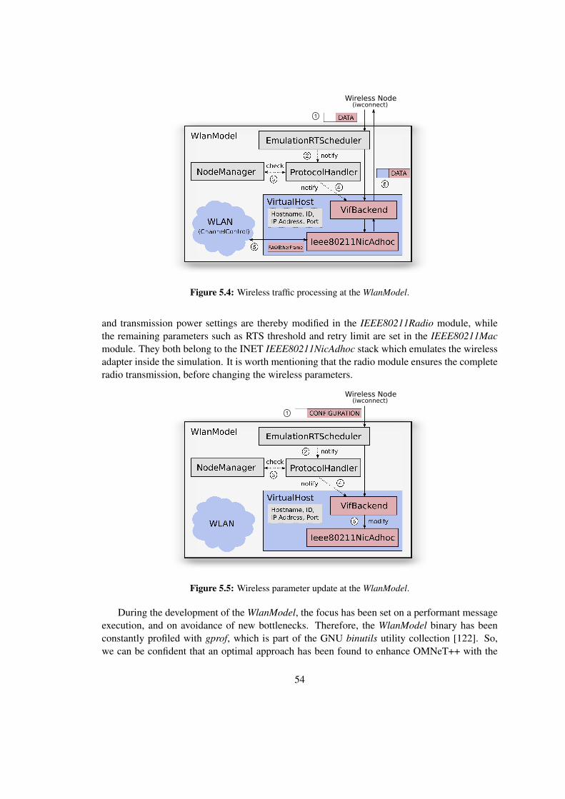
Wireless Node(iwconnect)
1
Figure 5.4: Wireless traffic processing at the WlanModel.
and transmission power settings are thereby modified in the IEEE80211Radio module, whilethe remaining parameters such as RTS threshold and retry limit are set in the IEEE80211Macmodule. They both belong to the INET IEEE80211NicAdhoc stack which emulates the wirelessadapter inside the simulation. It is worth mentioning that the radio module ensures the completeradio transmission, before changing the wireless parameters.
Wireless Node(iwconnect)
1
Figure 5.5: Wireless parameter update at the WlanModel.
During the development of the WlanModel, the focus has been set on a performant messageexecution, and on avoidance of new bottlenecks. Therefore, the WlanModel binary has beenconstantly profiled with gprof, which is part of the GNU binutils utility collection [122]. So,we can be confident that an optimal approach has been found to enhance OMNeT++ with the
54

required ‘host-in-the-loop interface’, used by the VirtualMesh wireless emulation. Additionally,the mechanism to influence the simulated device functionality from the wireless node adds com-pletely new possibilities for WMN application and protocol developers since this functionalitycannot be found in another emulation solution yet.
55


Chapter 6
Evaluation
VirtualMesh is a complex system, consisting of a high number of individual parts. By usingan emulation approach, VirtualMesh is creating a realistic wireless network, which supportsthe participation of real Linux hosts. In comparison to a network simulation, the evaluation ofa network emulation is therefore more complex. A simulation is an autonomous self-containedsystem, that already provides the necessary interface to setup the parameters and repeat the sameexperiment under different conditions. At the end, the results can be read from an accessiblelog file. In a network emulation, the creation of the experimental setup and the capturing ofperformance data requires a higher effort. The distributed nature of VirtualMesh makes highdemands on the logging and evaluation of the produced effects. The applications accessing thewireless network and generating the traffic reside on the individual Linux hosts, so the eventstriggering and logging has to be done there as well. Static parameters, such as the includedmobility model, or the playground size, have to be set in the WlanModel configuration on thesimulation host. Moreover, it is even possible to modify simulation parameters during run-time.Therefore, the repeatability of complex scenarios is much harder to achieve than in a simulation.We solved this issue by exactly scripting the actions and logging of an experimentation run. Aset of command-line scripts helps to run the performance measurements, which can randomly berepeated with different parameter values. The result of our efforts, are measurements which arerepresenting the normal operation of the operating system and applications with a high degreeof accuracy. Test runs made under the same conditions still may slightly vary, but this behaviouris expected and also necessary in order to evaluate a realistic scenario.
In this chapter, VirtualMesh is evaluated in terms of functionality and performance. In Sec-tion 6.1, the test configuration is introduced. A functional evaluation of VirtualMesh is presentedin Section 6.2, where a distributed mesh network between a number of virtualized Linux hostshas been built-up. The estimation of the emulation accuracy is based on performance measure-ments in various network scenarios. The comparison with the simulation counterparts, highlightcritical components and effects in the emulation. In Section 6.3, we were focusing on the packetround-trip time and in Section 6.4 on link throughput.
57

6.1 VirtualMesh Test Configuration
For the evaluation of VirtualMesh, a hosting environment, as shown in Figure 3.2, consistingof two servers has been used. One server is dedicated to run the WlanModel (Chapter 5). Theother server runs the Xen virtualization service (Section 3.3) with a number of virtual machines,representing the wireless nodes. The guest systems are running a Linux installation built bythe ADAM framework, introduced in Section 2.3.2. The connection between the two physicalservers is done through a 1 Gbps cross-link, dedicated to be used for the infrastructure networktraffic only. More details about the specific hard- and software setup can be found in Appendix A
The WlanModel is configured to emulate a common IEEE 802.11b wireless connection.Table 6.1 lists the static simulation parameters that have to be configured prior to the emulationrun. They do not change during emulation run-time. The wireless driver parameters (Table 6.2)are configured at the wireless nodes and reflected in the simulation after node registration.Although these parameters could be changed during an emulation run, this mechanism hasnot been evaluated, due to yet missing applications which could profit from a dynamic driverreconfiguration.
Description Parameter ValueNumber of radio channels **.channelcontrol.numChannels 13Maximum transmission power **.channelcontrol.pMax 50.0 mWSignal attenuation threshold **.channelcontrol.sat -110 dBmPath loss exponent **.channelcontrol.alpha 2Radio carrier frequency **.channelcontrol.carrierFrequency 2.4 GHzWireless device bitrate **.bitrate 11 MbpsContention window for normal data frames **.mac.cwMinData 32Contention window for broadcast frames **.mac.cwMinBroadcast 32Maximum queue length in frames **.mac.maxQueueSize 14Base noise level **.radio.thermalNoise -110 dBmSignal/Noise ratio threshold **.radio.snirThreshold 4 dB
Table 6.1: Static WlanModel IEEE 802.11b configuration.
Description ValueWireless channel 1Transmission power 17 dBmRadio sensitivity -85 mWRTS/CTS threshold 2346 B (off)Maximum number of retries 7
Table 6.2: Virtual wireless device (VIF) configuration.
The WlanModel is executed in command line mode as a system service on Linux. For thedetailed configuration, we refer to Appendix A.2. Before starting the emulation, we ensured that
58

no other system services are interfering and provoking additional system latencies. Namely cron,syslog and ntpd have to be stopped on our minimal server installation. After starting the model,the nice value of the relating process has been decreased to -20. This results in highest possibleCPU scheduling priority for the WlanModel process. With these steps, effects disturbing theemulation latency are minimised. These actions are eventually automated with help of an init-script. In case wireless emulation is not run for performance evaluation and some casual systemlatencies can be accepted, these steps are not required.
6.2 Functional Evaluation: ADAM
A big advantage of VirtualMesh is its integration of real Linux hosts. The modest soft- andhardware requirements of VirtualMesh provide compatibility to most Linux installations. In thissection, the use of ADAM Linux together with VirtualMesh is evaluated.
In a first test, we evaluated the compatibility of ADAM with the Xen virtualization setup.Per default, the kernel was missing the needed Xen support, as well as the TUN device driverrequired for the VirtualMesh client tools. For this reason, a new node profile ‘xen’ was addedto ADAM’s build-tool. The ‘xen’ profile contains the necessary changes to use ADAM in avirtualized environment, including VirtualMesh. These changes consist of the adapted Linuxkernel configuration and a modified network initialisation script, which automatically creates avirtual wireless interface with vifctl, in case no hardware wireless network device can be found.In this way, exactly the same environment can be provided, no matter if the ADAM Linuxsystem is running on real hardware or as a virtual machine on Xen. ADAM’s image-tool hasbeen adapted to create a virtual disk image, including the boot loader Grub [123], responsibleto start the correct system kernel. This disk image is then used to start the node in Xen. Oncerunning the image file can be accessed through the common block device interface also used withphysical hard disks. Of course, the ‘xen’ node type also includes the VirtualMesh client tools.With these changes, the ADAM Linux system gained full compatibility with the VirtualMeshXen environment and the WlanModel server.
In a next step, it has been tested, whether all the services provided by ADAM still work in thesame way as they do on a real hardware device. For this reason, the WlanModel simulation serverhas been started and several virtualized ADAM nodes have been connected with the emulatedwireless network. As expected, all wireless network operations are transparently handled byVirtualMesh. There are no difficulties to access a node’s Web server or login to a node via SSH,over the wireless network. All protocol stacks, including ARP, IPv4, UDP, TCP and also IPv6,fully cooperate with the wireless emulation. This is the expected behaviour, as the protocols arehandled by the Linux kernel of the nodes. For the unrestricted use of the emulation protocol,which connects the wireless nodes to the WlanModel server, an important remark should begiven here. Since it encapsulates the full Ethernet frame sent over the VIF, the packet size ofthe resulting DATA message is depending on the MTU of the VIF. If the MTU of the wirelessinterface is set to the usual 1500 bytes, the resulting DATA message exceeds this size due tothe additional header and message fields. The MTU of the infrastructure network interface(per default eth0) therefore has to be increased by at least 32 bytes (size of the DATA messageheader), to handle the maximal DATA message size without packet fragmentation. Alternatively,
59

the MTU of the VIF can be reduced. In our setup, we are using wireless MTU of 1500 bytes andan infrastructure network MTU of 2000 bytes.
A nice feature of ADAM is the distributed update mechanism for wireless node images andconfigurations [71, 124]. With the help of a Web interface [72], the network configuration of anentire WMN can be created and managed, and finally distributed to the actual wireless nodes.Also a system update on the wireless nodes can be graphically initiated. In the backgroundcfengine [125] is responsible to distribute the images and configurations. Since cfengine consistsof normal network services, again no difficulties are experienced by updating the node config-uration over the emulated wireless network. A system update is more complex as it includesthe reboot of the node. So, we are interested if this can be performed with VirtualMesh too. Asmentioned before, the virtual host can access its image file in the same manner as the hard disk.During the image update, the kernel and system image are copied to the node’s hard disk. Afterupdating the Grub configuration with the new default kernel entry, the node is rebooted into theupdated environment. Thanks to Xen’s pygrub [126], which reads the Grub configuration file ofa virtual machine, also the virtualized ADAM nodes are able to correctly boot the new system.
Using the mobility feature of INET, we finally evaluate the behaviour of ADAM with mobilewireless nodes. A scenario consisting of twelve virtualized wireless nodes has been set up,including some nodes, which are in permanent movement. In this situation the set of directneighbours is always changing and static network routes cannot be used any more. So, thedynamic routing daemon oslrd [127], which is a free implementation of the OLSR [10] protocol,has been started. By regularly exchanging its routing table with the neighbour nodes, knowledgeabout the reachable nodes and the required next-hop address for each, is collected. Accordingto the node movement in the simulation, olsrd is effectively able to find the next-hop addressfor all other involved wireless nodes. In this way, every node is able to communicate with everyother node, independent of the position and the neighbour nodes.
It has been shown, that VirtualMesh is able to fully virtualize a complex wireless network,without loosing any functionality. It is possible to imitate even the most complex wireless net-work architectures, as they can be found in WMNs and MANETs, without restricting the oper-ation of the participating OS and applications.
6.3 Performance Evaluation: Round-Trip Time
An important characteristic of a network link is the time used by a packet to reach its destina-tion. This property is normally identified by measuring the round-trip time (RTT). The RTTindicates the time required to send a packet to another network host and receive its immediatereply. As long as the delay is about the same in both directions, what is assumed to be true forVirtualMesh, this is a reliable approach. To measure the RTT the standard ping utility from theiputils package [128] is used. ping sends an ICMP Echo Request to a given host and measuresthe time needed to receive an ICMP Echo Reply from the other host.
60

6.3.1 Test Procedure
The measurements are performed with a payload size range from 56 bytes (default) to 1472 bytesin the wireless emulation and up to 1532 bytes in the infrastructure network. This ensures thatthe tests also cover the basic latency for packets with an larger size than the standard MTU,as it is necessary for our emulation protocol. In order to prevent packet fragmentation, theping command is run with the corresponding ‘-S do’ argument. Furthermore, the ping intervalis varied between 0.1 and 1 second, to analyse the different time pressure to the underlyingmedium. The latency tests are run for 1’000 seconds what gives a number of 1’000 to 10’000result values for each parameter configuration. If not further hinted, the RTT results mentionedin this chapter always represent the median value of a complete test series, summarizing theresults of the different packet sizes and transmission intervals. The exact results of the singlemeasurements can be found for each case in Appendix B. During the RTT measurements, theinvolved hosts were in idle state. This guarantees that no remarkable scheduling delays blurthe results. Caused by the included ARP look-up, the first RTT result is sometimes noticeablyhigher than the following measurements. This value is therefore not included in the analysis.
6.3.2 Infrastructure Network Latency
The emulated wireless communication has to cross the infrastructure network twice, once whensending a packet to the WlanModel and once when it forwards the packet to the destination node.This does not happen in a real wireless environment, so VirtualMesh includes an additional net-work delay. This delay might be even slightly larger when using system virtualization. Anotherdelay, not found in a real wireless network, is introduced through iwconnect (Section 4.3), whichencapsulates the wireless traffic into the emulation protocol for redirecting it to the WlanModelhost. This transformation is done in user-space and so it requires a number of timely expensivecontext switches. Summing up, at least three delaying effects in the VirtualMesh infrastructurenetwork influence the accuracy of the wireless emulation. These delays are the latency of thelocal network, the delay introduced through system virtualization and the latency introducedby traffic en-/decapsulation of the emulation protocol through iwconnect and the WlanModel.To evaluate this infrastructure latency, a number of RTT evaluation tests are run with differenthost combinations, also including node-to-node communication over the emulation protocol, aslisted in the following:
(a) Two physical hosts connected via 1 Gbps cross-link(b) Physical host to paravirtualized host connected via 1 Gbps cross-link(c) Physical host to full-virtualized host connected via 1 Gbps cross-link(d) Two physical hosts connected via 1 Gbps cross-link and using the emulation
protocol through iwconnect(e) Physical host to paravirtualized host connected via 1 Gbps cross-link and using
the emulation protocol through iwconnect
In the following, the general characteristics and some specific effects are discussed. A listwith the full results can be found in Appendix B.1. Figure 6.1 shows the comparison of theachieved results. The plot of a single setup summarises the whole range of parameter settings,
61

including different packet sizes and transmission intervals. It shows the maximal RTT as topbar, the minimal RTT as bottom bar and a box including the range between the 25% and 75%quartile. The thick line in the middle of the box depicts the median RTT value of all the series.
0
0.1
0.2
0.3
0.4
0.5
0.6
(a) (b) (c) (d) (e)
RTT
[ms]
Figure 6.1: Summarized RTT results for qualifying infrastructure network delay.
The median RTT of the native cross-link connection is about 0.19 ms for a payload of56 bytes and about 0.25 ms for a payload of 1532 bytes. This clearly indicates, that the RTTincreases for packets with a bigger size, which can be explained that it takes longer to fully placea big packet on the medium. The maximal RTT in the figure therefore depicts the average RTTwith the maximal payload size.
When comparing the RTT results of the native link (a) and the virtualization setups (b)(c), itcan be noticed that the system virtualization adds a minimal delay due to the additional packethandling layer in the virtualization server. When using paravirtualisation (PV) (b), this addi-tional delay averages in 0.04 to 0.06 ms. In the full virtualization setup (c), using the hardwareemulation layer (HVM), the additional delay can go up to nearly 0.3 ms, which is a multipleof the latency measured in the PV setup. This obviously has large impacts on the emulationaccuracy. As a consequence, only PV hosts are considered in our subsequent performance eval-uation. It is not shown in Figure 6.1, but noticeable, that the involvement of virtualization doesnot alter the characteristics of the traffic. The average standard deviation in all the measurementseries is around 15 µs.
Running the RTT measurement over a VIF, including iwconnect and the emulation protocol,the average latency overhead to the native connection is about 0.06 ms. However, an interestingeffect shows up. The RTT overhead of the physical-to-physical connection (d) does not resemblethe overhead of the physical to PV connection (e). As iwconnect is a user-space daemon, itsperformance is more sensitive to process scheduling and traffic characteristics. This is shownvisually in the Figures 6.2 and 6.3, which compare the RTT overhead and standard deviationcharacteristics to the native connection (a).
62

0 0.02 0.04 0.06 0.08
0.1 0.12 0.14
56 128256
512768
10241280
1472
[ms]
Packet size [Bytes]
RTT overhead iwconnect/1Gbps-native (d)RTT overhead iwconnect/1Gbps-PV (e)RTT standard deviation iwconnect/1Gbps-native (d)RTT standard deviation iwconnect/1Gbps-PV (e)
Figure 6.2: iwconnect/emulation protocol RTT overhead with respect to payload size.
Between two physical hosts the latency overhead of iwconnect is constant over all payloadsizes. When connecting to a virtualized host however, the overhead is in average about 0.02 mshigher and slightly increasing with the payload size. Also the standard deviation of the resultsis higher when using iwconnect and the emulation protocol. Independent of the payload size, ashort transmission interval leads to more outliners and thus a higher standard deviation.
Section summary
In order to conclude the analysis of the infrastructure network overhead, it can be statedthat both the paravirtualization and the emulation protocol with iwconnect individuallyadd a delay in a range of 0.04 to 0.08 ms. However, full virtualization multipliesthe RTT value and is therefore no reasonable option for performance evaluation withVirtualMesh. Additionally, it has to be accepted that iwconnect does slightly alter thetraffic characteristics when used in a virtualized environment, by increasing the jitterof the link, especially in case of short transmission intervals.
6.3.3 Wireless Emulation Accuracy
The VirtualMesh wireless emulation tries to imitate the packet latency of a real wireless connec-tion. In the previous section it has been shown, that the underlying infrastructure required to runVirtualMesh already introduces a minimal delay. This section is discussing the accuracy of theWlanModel simulation as well as the overall wireless emulation. To evaluate which componentsare influencing the result, the measurements of the VirtualMesh emulation are compared withthe results of a pure OMNeT++/INET simulation.
63
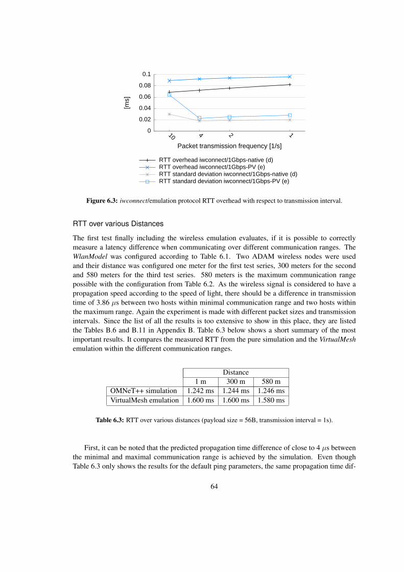
0
0.02
0.04
0.06
0.08
0.1
10 4 2 1[m
s]
Packet transmission frequency [1/s]
RTT overhead iwconnect/1Gbps-native (d)RTT overhead iwconnect/1Gbps-PV (e)RTT standard deviation iwconnect/1Gbps-native (d)RTT standard deviation iwconnect/1Gbps-PV (e)
Figure 6.3: iwconnect/emulation protocol RTT overhead with respect to transmission interval.
RTT over various Distances
The first test finally including the wireless emulation evaluates, if it is possible to correctlymeasure a latency difference when communicating over different communication ranges. TheWlanModel was configured according to Table 6.1. Two ADAM wireless nodes were usedand their distance was configured one meter for the first test series, 300 meters for the secondand 580 meters for the third test series. 580 meters is the maximum communication rangepossible with the configuration from Table 6.2. As the wireless signal is considered to have apropagation speed according to the speed of light, there should be a difference in transmissiontime of 3.86 µs between two hosts within minimal communication range and two hosts withinthe maximum range. Again the experiment is made with different packet sizes and transmissionintervals. Since the list of all the results is too extensive to show in this place, they are listedthe Tables B.6 and B.11 in Appendix B. Table 6.3 below shows a short summary of the mostimportant results. It compares the measured RTT from the pure simulation and the VirtualMeshemulation within the different communication ranges.
Distance1 m 300 m 580 m
OMNeT++ simulation 1.242 ms 1.244 ms 1.246 msVirtualMesh emulation 1.600 ms 1.600 ms 1.580 ms
Table 6.3: RTT over various distances (payload size = 56B, transmission interval = 1s).
First, it can be noted that the predicted propagation time difference of close to 4 µs betweenthe minimal and maximal communication range is achieved by the simulation. Even thoughTable 6.3 only shows the results for the default ping parameters, the same propagation time dif-
64

ference can be measured for the other transmission intervals and payload sizes. The results of theVirtualMesh emulation show an additional latency of about 0.35 ms. It can also be seen that theresults from the emulation even vary by up to 20 µs, what is clearly too much to accurately sim-ulate a propagation delay difference of 4 µs. That clearly shows, that different communicationranges and other wireless effects causing delays of only a few microseconds cannot realisticallybe imitated with the distributed emulation approach of VirtualMesh.
To further evaluate the emulation delay, the DATA traffic between the wireless nodes and theWlanModel server was analysed. With help of the tcpdump packet sniffer [129], it was recordedhow long a DATA message is processed inside the wireless simulation. This is indicating theactually accuracy of the soft real-time simulation. Unfortunately, the simulation part in the wire-less emulation is not able to precisely model the theoretical real-time latency with the requiredaccuracy. For all distances the time where the packets are processed in the WlanModel is withinmeasurement accuracy the same. For the previously listed payload size of 56 bytes and 1 secondtransmission interval, an ICMP packet stays in the WlanModel for about 0.48 ms. In the overallwireless RTT, this latency is included twice, once for each transmission direction. Summingit up with the previously measured delay for the VirtualMesh infrastructure network, where theRTT is about 0.274 ms for the mentioned ping configuration, the resulting emulation RTT shouldbe about 1.5 ms. The VirtualMesh emulation result of 1.6 ms (Table 6.3) mostly attests this theo-retical analysis. About one third of this value is therefore the infrastructure network delay. Thus,it can be concluded that the VirtualMesh real-time accuracy is mainly depending on the latencyof the underlying physical network.
RTT of different Traffic Characteristics
The behaviour of VirtualMesh with different work loads was evaluated by additional measure-ments with different transmission intervals and payload sizes. Again, there are two wirelessnodes involved as in the previous setup. The full range of RTT results can be found in Ap-pendix B, in Table B.7 for the emulation and Table B.12 for the simulation. While there areno abnormalities when comparing RTT results for different transmission intervals, a summaryof the VirtualMesh behaviour under various payload sizes is shown in Figure 6.4. Next to themedian values of the RTT also the minimal and maximal values are shown. It can be clearlyseen that the emulation results correspond nicely with the simulation results, with exception ofthe previously discussed latency overhead of about 0.35 ms in the emulation case. While thestandard deviation of the RTT values in VirtualMesh is comparable to the measured standard de-viation of a physical network, the simulation results have a wider distribution shown by the longerror bars in the figure. Even after extensive research we could not find the exact reason for thisbehaviour but it seems to indicate an anomaly in the simulation configuration or implementation.
RTT with Concurrent Network Load
The next experiment analyses the behaviour of the RTT, if there is a concurrent network streamkeeping the wireless model busy. Various stream bandwidths between 100 and 900 Kilo-bytes/s (KB/s) have been tested, while the maximal bit rate nearly fully saturates the wirelesslink. Again, the results from a pure OMNeT++ wireless simulation and the emulation with
65
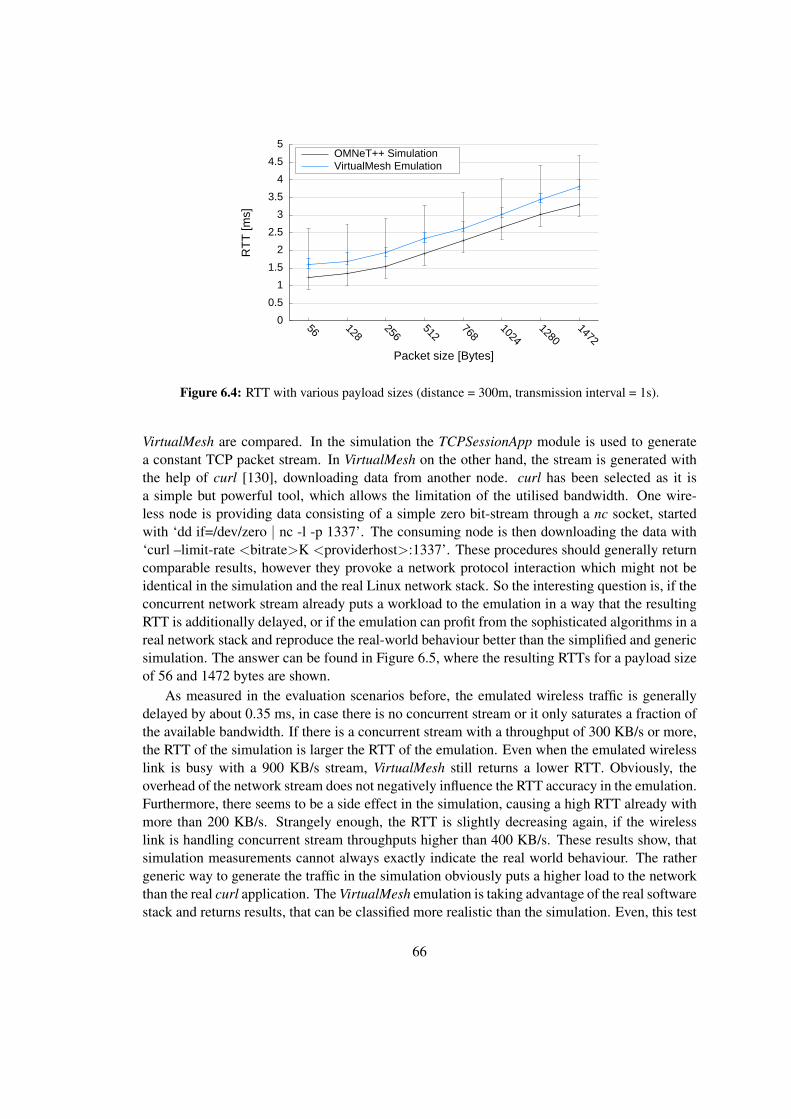
0 0.5
1 1.5
2 2.5
3 3.5
4 4.5
5
56 128256
512768
10241280
1472
RTT
[ms]
Packet size [Bytes]
OMNeT++ SimulationVirtualMesh Emulation
Figure 6.4: RTT with various payload sizes (distance = 300m, transmission interval = 1s).
VirtualMesh are compared. In the simulation the TCPSessionApp module is used to generatea constant TCP packet stream. In VirtualMesh on the other hand, the stream is generated withthe help of curl [130], downloading data from another node. curl has been selected as it isa simple but powerful tool, which allows the limitation of the utilised bandwidth. One wire-less node is providing data consisting of a simple zero bit-stream through a nc socket, startedwith ‘dd if=/dev/zero | nc -l -p 1337’. The consuming node is then downloading the data with‘curl –limit-rate <bitrate>K <providerhost>:1337’. These procedures should generally returncomparable results, however they provoke a network protocol interaction which might not beidentical in the simulation and the real Linux network stack. So the interesting question is, if theconcurrent network stream already puts a workload to the emulation in a way that the resultingRTT is additionally delayed, or if the emulation can profit from the sophisticated algorithms in areal network stack and reproduce the real-world behaviour better than the simplified and genericsimulation. The answer can be found in Figure 6.5, where the resulting RTTs for a payload sizeof 56 and 1472 bytes are shown.
As measured in the evaluation scenarios before, the emulated wireless traffic is generallydelayed by about 0.35 ms, in case there is no concurrent stream or it only saturates a fraction ofthe available bandwidth. If there is a concurrent stream with a throughput of 300 KB/s or more,the RTT of the simulation is larger the RTT of the emulation. Even when the emulated wirelesslink is busy with a 900 KB/s stream, VirtualMesh still returns a lower RTT. Obviously, theoverhead of the network stream does not negatively influence the RTT accuracy in the emulation.Furthermore, there seems to be a side effect in the simulation, causing a high RTT already withmore than 200 KB/s. Strangely enough, the RTT is slightly decreasing again, if the wirelesslink is handling concurrent stream throughputs higher than 400 KB/s. These results show, thatsimulation measurements cannot always exactly indicate the real world behaviour. The rathergeneric way to generate the traffic in the simulation obviously puts a higher load to the networkthan the real curl application. The VirtualMesh emulation is taking advantage of the real softwarestack and returns results, that can be classified more realistic than the simulation. Even, this test
66

0
2
4
6
8
10
12
14
16
18
0 100 200 300 400 600 900
RTT
[ms]
Stream bandwidth [KB/s]
Simulation 56 BytesSimulation 1472 BytesEmulation 56 BytesEmulation 1472 Bytes
Figure 6.5: RTT with concurrent streams (distance = 300m, transmission interval = 1s).
setup is very basic, it shows the advantage of having the real kernel and real applications in awireless network evaluation.
Section summary
The accuracy that can be achieved with VirtualMesh is clearly depending on the com-plexity of the scenario and the underlying hardware. In the evaluation an average RTToverhead of about 0.35 ms, in comparison with the simulation, was measured. Onlya fraction of that value is caused by the simulation overhead, but mostly it is influ-enced by the network latency of the infrastructure network. The main factor affectingthe VirtualMesh accuracy is therefore the underlying network. Despite this increasednetwork delay, it could be shown that VirtualMesh is able to realistically represent areal-world condition. When measuring the RTT with concurrent network transfers, thesimulation seems to suffer by an inaccurate protocol behaviour. This does not happenwith the real network stack of Linux in VirtualMesh.
6.3.4 WlanModel Scalability
This section evaluates the influence of the number of virtual nodes on the emulation accuracy.So far the basic RTT behaviour under different conditions and aspects has been evaluated, butonly using two wireless nodes. Regarding the computational effort of the wireless emulation,this can be seen as a best case scenario. Normally, a distributed wireless setup, as it is used inWMNs, consists of up to a dozen or more nodes. We can expect that any additional node addssome overhead, since the propagation model has to check their position and state too, no matterif they participate in an actual packet transmission or not.
67

Simulation Latency Overhead
In order to quantify the simulation model overhead of uninvolved hosts, the RTT between twowireless nodes, node01 and node02, is measured with a different number of additional nodeswithin transmission range. They are placed in a grid around node01 and node02. Again, the testprocedure described in Section 6.3.1 has been followed. An extensive list of the achieved resultscan be found in Table B.10, which is placed as usual in Appendix B.2. A statistical analysisthereof is shown in Figure 6.6.
0 0.2 0.4 0.6 0.8
1 1.2 1.4 1.6 1.8
2 2.2 2.4
2 3 4 5 8 12 0
10
20
30
40
50
60
70
RTT
[ms]
Del
ay [µ
s]
Number of wireless nodes
RTT overhead per host
Figure 6.6: WlanModel scalability (distance = 300m, transmission interval = 1s, payload size = 56B).
The results clearly show an influence of the uninvolved nodes. It is interesting, that the in-troduced overhead per node is not constant, but roughly proportional to the number of additionalhosts. VirtualMesh is clearly suffering from the soft real-time approach under this condition.The radio propagation model has to check every additional hosts if it can potentially receive thesent ICMP packets, which increases the total transmission latency for the transferred packet. Ithas to be noted, that the virtualization technique does not influence these results, because thiseffect is only caused by the MAC layer computations, which are entirely done in the WlanModel.
Multi-hop Latency
Another test to evaluate the scalability behaviour of the WlanModel, is the evaluation of themulti-hop performance. For this reason, a number of wireless nodes are placed in a row. Theirnetwork routes are configured in a way, that they are only able to communicate with the imme-diate neighbours in the row. This means for the RTT measurements that each intermediate nodehas to receive the ICMP packet and forward to the next-hop neighbour. To minimise the over-head of uninvolved nodes a transmission range of 500 meters has been selected, so that each hostcan anyway only reach its next-hop neighbours. In this way, the limited interference distance ofthe ChannelControl module, described in Section 5.1.9, should engage and omit the receptionchecks for uninvolved hosts.
68

Again, the tests are done with VirtualMesh and in an OMNeT++ simulation. The detailedresults of the measurements can be found in Appendix B, in Table B.9 for VirtualMesh and inTable B.14 for OMNeT++. A summary of these results is shown in Figure 6.7. Surprisingly,the VirtualMesh results correspond well with the simulation counterparts. A per-hop networklatency overhead of the emulation cannot be experienced in this test. The RTT results of thesimulation partially seem a bit too high, what could be caused by a different ARP lookup be-haviour in OMNeT++/INET and VirtualMesh. Only for more than six hops, VirtualMesh adds anoticeable latency overhead to the RTT. Generally, the emulation is perfectly able to imitate themulti-hop behaviour of a wireless network. This is crucial for the decentralised WMN commu-nication model.
0
5
10
15
20
25
30
1 2 3 4 5 6 7 8 9 10
RTT
[ms]
Number of hops
OMNeT++ SimulationVirtualMesh Emulation
Figure 6.7: WlanModel multi-hop behaviour (distance = 500m, transmission interval = 1s, payload size= 56B).
Section summary
During the scalability evaluation of VirtualMesh, several effects have been identified.First, we note that the number of hosts within a transmission area is influencing theresult. More hosts lead to a bigger effort in evaluating the reception host and thereforeincreases the overall latency of the wireless packet. On the other hand, in the multi-hop scenario, the VirtualMesh emulation corresponds well with the simulation. Onlyfor more than six hops, an additional latency overhead through the emulation can beexperienced. Generally, the scalability behaviour of VirtualMesh is good. Neither theXen virtualization, nor the emulation model is restricting the use of VirtualMesh withup to a dozen tested nodes.
6.4 Performance Evaluation: Bandwidth
Another important property of a network link is the offered bandwidth capacity. Especially forwireless links, this can be a critical factor. The recent wireless specifications still only support
69

a bandwidth much lower than what is common in a wired network. We therefore evaluated thebandwidth performance of VirtualMesh and compared it with the OMNeT++ simulation results.
6.4.1 Test Procedure
The measurement of the offered bandwidth capacity is not that simple. There is no instrumentto measure the pure peer-to-peer throughput without making use of a transport layer protocol.However, each protocol also clams a portion of the offered bandwidth for its protocol head-ers and connection management which then influences the resulting payload throughput. Tomeasure the actual bandwidth the network link has to be totally saturated. Unfortunately, mostnetwork protocols have mechanisms to prevent this in order to guarantee a fluent communica-tion. Therefore retransmission and buffering effects can come into play here. We encounteran additional difficulty when comparing the simulation and emulation results. Neither the ex-act transport protocol implementation nor the overlaying benchmark application from the realwireless node can be used in the simulation environment.
In order to measure the maximal throughput in the emulation case, we use the netperf util-ity [131]. It supports a wide range of performance tests and parameters. We found that theTCP STREAM test gives the most reliable results and therefore choose this for our evaluation.The duration of the test is increased with the argument ’-l 300’ to 5 minutes. To confirm thenetperf results the time needed to transfer a 200 MB file transfer via busybox’s nc tool hasbeen measured. On one host nc is started in the listening mode by running ‘nc -p 1337 -l >>/dev/zero’. From the other host the file is sent to the listening host, by executing ‘time ddif=/dev/zero bs=1M count=200 | nc <targethost> 1337’. If the transfer is finished, the passedtime is printed to the command line.
In the simulation case, several different approaches are followed to measure the throughput.The INET’s Sink module together with the EtherClientApp are used to measure the link layerthroughput. For gaining more comparable results of the transport layer throughput the UDP andTCP application modules are considered. The according UDPSinkApp and TCPSinkApp havebeen modified to sample the throughput after every received frame. The TCP throughput testis then done with the TCPSessionApp sending a bulk transfer of 200 MB to the receiver andmeasure the time until completion. The UDP throughput test is done with the UDPBasicAppsending 1 MB sized packets in short intervals to saturate the link and check the amount oftransferred data after 300 seconds.
6.4.2 VirtualMesh Throughput
Unlike with the RTT tests, the influence of the hardware setup has a smaller influence on thethroughput measurements. With our cross-connected 1 Gbps link, netperf returns a throughputof 113.07 MB/s to the native host and 72.33 MB/s to a virtualized host respectively. Unfortu-nately, if using the VIF, together with iwconnect and the emulation protocol, the throughput isroughly halved. With this setup only a maximal throughput of 68.30 MB/s in the native caseand 38.19 MB/s with a virtualized host could be achieved. The overhead in context switchingand en-/decapsulating the traffic with iwconnect does not seem to scale properly up to a band-width of 1 Gbps per second. The provided bandwidth is still more than enough for experiments
70

with a IEEE 802.11b wireless network, which has a specified bandwidth of maximal 11 Mbps(1.375 MB/s).
To analyse the throughput of the different test methodologies (Section 6.4.1) each bench-mark is run with a multiple of concurrent transmissions. In this way, it can be evaluated howthe throughput scales with concurrent clients. The measured bandwidth capacity in the differenttest cases are shown in Figure 6.8. At a first glance, it may be disappointing that a result, noteven close to the expected 11 Mbps could be achieved. For a IEEE 802.11b wireless networkthe gained results are still correct as shown in [55]. The reason can be found in the mechanismsof the IEEE 802.11 protocol. The available bandwidth for the overlaying communication pro-tocols is decreased by the fact, that transport layer transmission is randomly delayed throughCSMA/CA and frames are individually acknowledged. It is noticeable, that the Ethernet andUDP benchmarks are missing in the case of concurrent transmissions. This is because these pro-tocols do not support any congestion avoidance mechanisms and therefore the first connectionstream does already saturate the link in a way that the other streams get dropped. Furthermore, itcan be recognised that the test results of the simpler protocols show a slightly higher throughputthan their protocol specific implementations. But generally, the tests confirm each other and re-alistically scale with the number of parallel transfers. Unfortunately, there seems to be an issuewith the TCP behaviour in the simulation. It has been confirmed by the developers of OMNeT++that the TCP protocol has some problems when runing over a wireless network. Nonetheless,the achieved results are presented for later reference.
0 0.5
1 1.5
2 2.5
3 3.5
4 4.5
5
1 2 3 4 0
0.1
0.2
0.3
0.4
0.5
0.6
Thro
ughp
ut [M
bps]
Throughput [MB/s]
Number of parallel transfers
Simulation EthernetSimulation UDPSimulation TCP
VirtualMesh netperfVirtualMesh nc
Figure 6.8: Parallel stream throughput results.
The throughput behaviour is also analysed over various hops. The wireless nodes setup isthe same as in the previous multi-hop evaluation in Section 6.3.4. As Figure 6.9 shows, the Vir-tualMesh results are realistic. They exactly match the values from the simulation. IEEE 802.11bdivides the totally available bandwidth among the clients, so with every additional hop, the end-to-end throughput is decreasing proportionally. VirtualMesh accurately imitates the expectedbandwidth of an IEEE 802.11b network up to four hops. Afterwards, the achieved bandwidthwith VirtualMesh is minimally lower than in the simulation.
71

0 0.5
1 1.5
2 2.5
3 3.5
4 4.5
5
1 2 3 4 5 0
0.1
0.2
0.3
0.4
0.5
0.6
Thro
ughp
ut [M
bps]
Throughput [MB/s]
Number of hops
OMNeT++ UDP ThroughputVirtualMesh netperf
Figure 6.9: Multi-hop throughput results.
Section summary
The throughput behaviour of the VirtualMesh wireless emulation is able to matchthe pure simulation case. In terms of maximal throughput, concurrent streams andmulti-hop communication we are able to model the correct bandwidth capacity of aIEEE 802.11b wireless link.
72

Chapter 7
Conclusion and Future Work
This chapter summarises the experience we made by implementing and evaluating the Vir-tualMesh emulation framework. Furthermore, some ideas are given how VirtualMesh couldbe extended and improved in future work.
7.1 Conclusion
With VirtualMesh a new instrument for wireless protocol and application developers is intro-duced. It consists of a modular platform which allows real operating systems and applicationsto be tested in a complex wireless network environment. VirtualMesh differs from other simi-lar solutions that it sets minimal restrictions to the supported wireless clients and offers a trueprotocol independence. It has been shown that the full functionality of an OS and its applica-tions can be used. Another prominent feature is the full control of the emulated wireless devicethrough the native OS configuration tools. This feature allows new possibilities for testing ap-plications, which dynamically adapt the functionality of the wireless network interface, as it isused in multi-channel/multi-interface networking solutions.
The inclusion of the OMNeT++ simulation framework has shown to provide a flexible emu-lation model, which can easily be extended and modified. VirtualMesh is adding the integrationof the ‘host-in-the-loop’ technique to handle real network traffic within the simulation environ-ment. Together with the INET radio propagation and mobility model, a configurable scenariofor all kind of WMN and MANET experiments can be set up and tested.
Although, the emulation technique does not guarantee a timely correct computation of thelatencies caused by wireless transmission, the evaluation of VirtualMesh attests an accuracy ofless than a millisecond and is mainly caused by the network delay of the infrastructure network.The accuracy of the simulation model does only have a minor influence on the overall latency,as we have shown with the node distance experiment. By using a soft real-time scheduler italso has to be accepted, that the packet delay is influenced by the computational effort of thesimulation model. This can be seen for example by the slight increase of the RTT in scenarioswith additional uninvolved hosts being placed inside the transmission area. In the end, theselatency effects are mostly important when doing performance evaluations based on VirtualMesh.The overall functionality of the emulation is not hampered by these delays.
73
Regarding the bandwidth capacity the VirtualMesh can satisfy the specifications of anIEEE 802.11b network. Even over multiple hops, the expected throughput could be achieved.
Our evaluation based on the Xen virtualization, has shown, that VirtualMesh can seamlesslyintegrate with the available platform virtualization tools. The emulation accuracy is taking bigadvantage of the improved I/O-layer found in the paravirtualization approach. Hence, especiallyXen can be recommended as virtualization platform.
Refering back to the motivation of VirtualMesh (Section 1.4), most of the goals wereachieved. VirtualMesh can be used as an extensible development, testing and evaluation frame-work that fully integrates into a Linux environment. It does not offer the high accuracy as foundin conventional network simulations. Especially for network protocol development, it still maybe required to evaluate a proof-of-concept implementation in the simulation. However, Vir-tualMesh can help to test a real-world implementation. This is valuable when analysing thefunctionality and compatibility of a protocol or application under realistic conditions.
The work presented in this thesis has contributed to two publications [97, 98]. VirtualMeshis freely available from the software repository of the research group ‘Computer Networks andDistributed Systems’ at the Institute of Computer Science and Applied Mathematics of theUniversity of Bern. It can be downloaded as source code and Debian Linux packages underhttp://www.iam.unibe.ch/∼rvs/research/software.html
7.2 Future Work
The flexible approach of VirtualMesh offers many areas of improvements and interesting exten-sions. With some additional work the scope of VirtualMesh could be drastically widened. In thefollowing some ideas about valuable enhancements are presented.
So far the emulation uses a pre-defined network stack which only allows to createIEEE 802.11b network devices. For an IEEE 802.11g adapter or even only a IEEE 802.11badapter in access point mode, another module is required in the OMNeT++ simulation. There-fore the emulation model could be enhanced to automatically load the correct network devicemodule depending on the virtual device on the host. This idea can be continued towards a freelyconfigurable simulation network stack. The client tools could be extended to support any pos-sible network device. It would require that we can give vifctl the type of the desired virtualnetwork interface. Next to wireless interfaces also Bluetooh, WiMAX, PPP, FastEthernet orany other type of network devices, for which a simulation model exists, could be supported byVirtualMesh.
Another enhancement includes the use of different wireless card profiles with their specifichardware capabilities. So far a rather generic set of parameters derived from an Atheros/Madwificard/driver combination is loaded. libvif could be extended to offer different network card pro-files with distinct parameter ranges and default settings. This would make it possible to comparedifferent network adapter types in the emulated environment. So far, the network overhead inVirtualMesh and the rather simple radio propagation model do not support the fidelity for suchdetailed wireless device models.
It would be also possible to extend the capabilities of libvif to track the run-time statisticsfrom the emulated wireless adapter. Since logging is disabled in the emulation for performance
74
reasons, the number of successfully submitted, received and dropped frames could be madeaccessible to the iwconfig/ifconfig tools, would further allow the host to react on such events.This could be useful for a dynamic WMN routing protocol as an example.
Since the Linux wireless development is breaking away more and more from the WirelessExtension API, and is turning towards the Netlink-based configuration interface, libvif may notbe compatible to future wireless networking tools. Already now, the configuration of a VIF isnot possible with the next generation wireless interface configuration tool . If compatibility withthis tool is required, either has to be adapted to query the Wireless Extension API or libvif hasto be extended with a compatible Netlink interface. Though both solutions may require someeffort. But also the current version of libvif is not becoming obsolete soon, since most wirelessdrivers in the Linux kernel are still using the Wireless Extension API and therefore is not beingdeprecated in a predictable time frame.
To overcome the mentioned scalability issues, VirtualMesh could be combined with the syn-chronised emulation approach found in [95]. The idea of synchronising the timers of the virtual-ization and simulation environment would finally invalidate the current complexity restrictions.Combined with the features mentioned above, this solution could be even enhanced to an ex-tended, fully-featured wireless network development platform, which would be able to providean accuracy close to a simulation and still include the real OS and real applications.
For the wireless model, the area possible enhancements are nearly unlimited. We have cho-sen the default INET propagation model for our evaluation. But there exist alternative imple-mentations, for example in the MiXiM framework. They implement a more sophisticated MAClayer, which could be adapted to satisfy the WlanModel setup. Anyway, VirtualMesh is also apossible instrument for testing enhanced radio propagation model under real traffic conditions.A possible operation purpose in this area could be the calibration of a wireless model accordingto measurements taken in a re-playable traffic scenario on real wireless nodes.
75

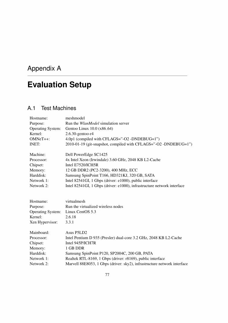
Appendix A
Evaluation Setup
A.1 Test Machines
Hostname: meshmodelPurpose: Run the WlanModel simulation serverOperating System: Gentoo Linux 10.0 (x86 64)Kernel: 2.6.30-gentoo-r4OMNeT++: 4.0p1 (compiled with CFLAGS=”-O2 -DNDEBUG=1”)INET: 2010-01-19 (git-snapshot, compiled with CFLAGS=”-O2 -DNDEBUG=1”)
Machine: Dell PowerEdge SC1425Processor: 4x Intel Xeon (Irwindale) 3.60 GHz, 2048 KB L2-CacheChipset: Intel E7520/ICH5RMemory: 12 GB DDR2 (PC2-3200), 400 MHz, ECCHarddisk: Samsung SpinPoint T166, HD321KJ, 320 GB, SATANetwork 1: Intel 82541GI, 1 Gbps (driver: e1000), public interfaceNetwork 2: Intel 82541GI, 1 Gbps (driver: e1000), infrastructure network interface
Hostname: virtualmeshPurpose: Run the virtualized wireless nodesOperating System: Linux CentOS 5.3Kernel: 2.6.18Xen Hypervisor: 3.3.1
Mainboard: Asus P5LD2Processor: Intel Pentium D 935 (Presler) dual-core 3.2 GHz, 2048 KB L2-CacheChipset: Intel 945P/ICH7RMemory: 1 GB DDRHarddisk: Samsung SpinPoint P120, SP2004C, 200 GB, PATANetwork 1: Realtek RTL-8169, 1 Gbps (driver: r8169), public interfaceNetwork 2: Marvell 88E8053, 1 Gbps (driver: sky2), infrastructure network interface
77

Notes:
• The infrastructure network devices were cross-connected via a 2 meter Cat-5e Ethernetcable.
• The MTU of the infrastructure network has been set to 2000 bytes. This is requiredto handle the emulation protocol (Section 3.2) with a maximal DATA message size of1532 bytes, without fragmentation.
A.2 OMNeT++ Configuration for the WlanModel
The classical way to manage an OMNeT++ simulation is by invoking its built-in Tk GUI. Inthe VirtualMesh emulation approach we need to run the WlanModel simulation as a daemonlistening for the wireless client traffic. We therefore make use of the alternative command lineinterface. This can be selected by invoking WlanModel with the ’-u Cmdenv’ parameter. Sincewe try to run OMNeT++ in real-time, every simulation-related overhead has to be minimized.The performance critical parameters, which should be set in the ‘.ini’ configuration file areshown in Listing A.3.
scheduler-class = "cUDPSocketRTScheduler" # select our custom scheduler
cmdenv-express-mode = true # set express mode (soft real-time)cmdenv-interactive = false # don’t ask for user feedbackcmdenv-performance-display = false # don’t show performance status
record-eventlog = false # don’t record stuff
**.vector-recording = false
**.scalar-recording = false
Listing A.1: WlanModel OMNeT++ configuration.
Depending on the selected mobility model, different parameters have to be set in theconfiguration file. Listing A.2 is showing a simple example configuration. Host 0 uses theNullMobility module and therefore has a static position. Host 1 uses the LinearMobility module,which takes another parameter ‘speed’. The position of this host is moving with the given speedalong the x axis.
**.playgroundSizeX = 100
**.playgroundSizeY = 100
*.host[0].mobilityType = "NullMobility"
*.host[0].mobility.x = 20
*.host[0].mobility.y = 10
*.host[1].mobilityType = "LinearMobility"
*.host[1].mobility.speed = 3mps
*.host[1].mobility.x = 10
*.host[1].mobility.y = 20
Listing A.2: Example wireless node position configuration.
78
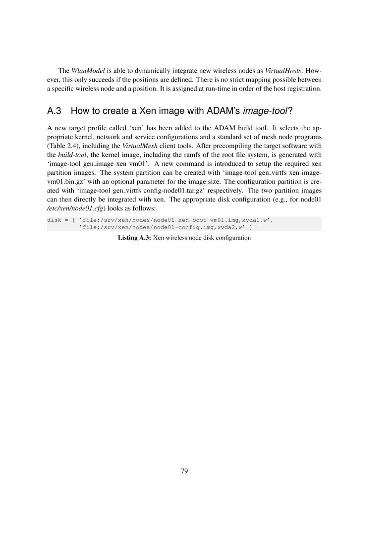
The WlanModel is able to dynamically integrate new wireless nodes as VirtualHosts. How-ever, this only succeeds if the positions are defined. There is no strict mapping possible betweena specific wireless node and a position. It is assigned at run-time in order of the host registration.
A.3 How to create a Xen image with ADAM’s image-tool?
A new target profile called ‘xen’ has been added to the ADAM build tool. It selects the ap-propriate kernel, network and service configurations and a standard set of mesh node programs(Table 2.4), including the VirtualMesh client tools. After precompiling the target software withthe build-tool, the kernel image, including the ramfs of the root file system, is generated with‘image-tool gen image xen vm01’. A new command is introduced to setup the required xenpartition images. The system partition can be created with ‘image-tool gen virtfs xen-image-vm01.bin.gz’ with an optional parameter for the image size. The configuration partition is cre-ated with ‘image-tool gen virtfs config-node01.tar.gz’ respectively. The two partition imagescan then directly be integrated with xen. The appropriate disk configuration (e.g., for node01/etc/xen/node01.cfg) looks as follows:
disk = [ ’file:/srv/xen/nodes/node01-xen-boot-vm01.img,xvda1,w’,’file:/srv/xen/nodes/node01-config.img,xvda2,w’ ]
Listing A.3: Xen wireless node disk configuration
79


Appendix B
Evaluation Results
All test are automatically done with a wide range of parameter settings. It is not possible towrite down all results in this place. But at least a representative choice should be given here forindividual analysis. RTT results of intermediate packet sizes or ping intervals are omitted.
B.1 Infrastructure Evaluation Results
(a) Physical to physical host
Payload size Send interval Minimal 1st quartile Median 3rd quartile Maximal Stddev[bytes] [s] RTT [ms] [ms] RTT [ms] [ms] RTT [ms] [ms]
560.1 0.149 0.168 0.181 0.193 1.080 0.0170.5 0.155 0.175 0.188 0.201 0.280 0.0161 0.156 0.175 0.187 0.200 0.225 0.015
14720.1 0.135 0.226 0.238 0.251 2.740 0.0310.5 0.209 0.228 0.241 0.254 0.305 0.0151 0.213 0.232 0.245 0.257 0.300 0.015
15320.1 0.209 0.228 0.240 0.253 1.490 0.0220.5 0.211 0.230 0.243 0.255 0.298 0.0151 0.212 0.234 0.247 0.259 0.297 0.015
Table B.1: RTT of 1 Gbps cross-link.
81

(b) Physical to paravirtualized host
Payload size Send interval Minimal 1st quartile Median 3rd quartile Maximal Stddev[bytes] [s] RTT [ms] [ms] RTT [ms] [ms] RTT [ms] [ms]
560.1 0.188 0.212 0.226 0.239 0.349 0.0180.5 0.194 0.219 0.233 0.246 0.375 0.0201 0.200 0.225 0.238 0.250 0.310 0.017
14720.1 0.247 0.269 0.282 0.295 3.940 0.0410.5 0.252 0.278 0.291 0.304 0.413 0.0181 0.259 0.287 0.300 0.313 0.384 0.017
15320.1 0.260 0.281 0.294 0.307 3.560 0.0380.5 0.265 0.291 0.303 0.316 0.389 0.0171 0.268 0.299 0.312 0.325 0.446 0.018
Table B.2: RTT of 1 Gbps cross-link to PV host.
(c) Physical to full virtualized host
Payload size Send interval Minimal 1st quartile Median 3rd quartile Maximal Stddev[bytes] [s] RTT [ms] [ms] RTT [ms] [ms] RTT [ms] [ms]
560.1 0.291 0.448 0.461 0.475 1.810 0.0250.5 0.413 0.447 0.461 0.475 0.952 0.0271 0.414 0.453 0.467 0.482 0.987 0.028
14720.1 0.354 0.508 0.521 0.534 0.689 0.0200.5 0.474 0.516 0.530 0.544 0.662 0.0221 0.484 0.514 0.529 0.543 0.847 0.026
1532 Xen does not allow to set a MTU > 1500 for HVM guests
Table B.3: RTT of 1 Gbps cross-link to HVM host.
82

(d) Physical to physical host via iwconnect /emulation protocol
Payload size Send interval Minimal 1st quartile Median 3rd quartile Maximal Stddev[bytes] [s] RTT [ms] [ms] RTT [ms] [ms] RTT [ms] [ms]
560.1 0.201 0.240 0.253 0.266 0.377 0.0170.5 0.223 0.250 0.263 0.276 0.359 0.0191 0.226 0.260 0.274 0.287 0.343 0.019
14720.1 0.246 0.299 0.312 0.324 0.456 0.0170.5 0.252 0.310 0.323 0.336 0.429 0.0191 0.260 0.321 0.334 0.348 0.421 0.020
Table B.4: RTT of 1 Gbps cross-link via iwconnect/emulation protocol.
(e) Physical to paravirtualized host via iwconnect
Payload size Send interval Minimal 1st quartile Median 3rd quartile Maximal Stddev[bytes] [s] RTT [ms] [ms] RTT [ms] [ms] RTT [ms] [ms]
56
0.1 0.201 0.240 0.253 0.266 0.377 0.0210.5 0.223 0.250 0.263 0.276 0.359 0.0241 0.226 0.260 0.274 0.287 0.343 0.025
1472
0.1 0.368 0.399 0.413 0.426 0.687 0.0200.5 0.380 0.406 0.420 0.433 0.564 0.0241 0.354 0.417 0.433 0.448 0.573 0.029
Table B.5: RTT of 1 Gbps cross-link to PV host via iwconnect/emulation protocol
83

B.2 VirtualMesh Evaluation Results
Node Payload Send Minimal 1st quartile Median 3rd quartile Maximal Stddevdistance size interval RTT RTT RTT RTT RTT
[ms][m] [bytes] [s] [ms] [ms] [ms] [ms] [ms]
1
560.1 1.46 1.53 1.56 1.59 1.73 0.0350.5 1.48 1.56 1.59 1.61 2.48 0.0491 1.50 1.58 1.60 1.63 1.73 0.042
14720.1 3.72 3.79 3.80 3.82 3.97 0.0250.5 3.72 3.79 3.81 3.82 4.01 0.0311 3.73 3.80 3.82 3.84 3.95 0.032
300
560.1 1.48 1.54 1.57 1.59 1.70 0.0340.5 1.48 1.55 1.58 1.60 1.75 0.0401 1.50 1.57 1.60 1.62 1.78 0.042
14720.1 3.74 3.79 3.81 3.82 3.97 0.0260.5 3.72 3.79 3.80 3.82 3.98 0.0291 3.73 3.79 3.81 3.83 4.01 0.032
580
560.1 1.47 1.54 1.56 1.59 1.91 0.0400.5 1.470 1.55 1.58 1.61 1.80 0.0431 1.49 1.55 1.58 1.61 1.77 0.042
14720.1 3.72 3.79 3.80 3.82 3.98 0.0280.5 3.72 3.79 3.81 3.82 12.80 0.3901 3.73 3.79 3.81 3.83 10.10 0.202
Table B.6: RTT results of various distances with VirtualMesh emulation.
Payload Send Minimal 1st quartile Median 3rd quartile Maximal Stddevsize interval RTT RTT RTT RTT RTT
[ms][bytes] [s] [ms] [ms] [ms] [ms] [ms]
56 0.1 1.47 1.55 1.58 1.60 2.44 0.0421 1.50 1.57 1.60 1.62 1.78 0.042
128 0.1 1.59 1.68 1.70 1.71 2.12 0.0381 1.59 1.67 1.69 1.71 1.95 0.040
256 0.1 1.81 1.89 1.90 1.92 2.95 0.0371 1.83 1.9 1.94 1.97 2.08 0.044
512 0.1 2.21 2.29 2.30 2.32 2.65 0.0421 2.23 2.3 2.33 2.36 2.52 0.041
768 0.1 2.49 2.61 2.63 2.66 121.00 1.8381 2.53 2.61 2.62 2.64 2.81 0.032
1024 0.1 2.93 3.01 3.02 3.04 11.20 0.1661 2.94 3.01 3.03 3.05 3.23 0.034
1280 0.1 3.34 3.41 3.42 3.44 10.10 0.0871 3.35 3.41 3.43 3.45 3.62 0.035
1472 0.1 3.65 3.73 3.75 3.79 10.60 0.1241 3.73 3.79 3.81 3.83 4.01 0.032
Table B.7: RTT results of various payload sizes with VirtualMesh emulation (distance = 300m).
84

Stream Payload Send Minimal 1st quartile Median 3rd quartile Maximal Stddevthroughput size interval RTT RTT RTT RTT RTT RTT
[ms][KB/s] [bytes] [s] [ms] [ms] [ms] [ms] [ms]
100
560.1 1.46 1.55 1.58 1.67 17.50 3.7850.5 1.49 1.56 1.595 1.67 16.90 3.7041 1.50 1.58 1.61 1.72 18.70 3.735
14720.1 3.65 3.73 3.77 3.85 20.40 3.7150.5 3.66 3.76 3.79 3.86 17.80 3.5671 3.70 3.78 3.82 4.18 19.00 3.935
200
560.1 1.46 1.57 1.61 10.00 19.30 5.0550.5 1.47 1.58 1.64 9.53 23.40 5.0401 1.49 1.60 1.74 10.10 19.90 5.216
14720.1 3.65 3.76 3.80 12.20 20.30 5.0590.5 3.70 3.78 3.825 12.00 21.70 5.0111 3.70 3.81 3.87 13.10 18.90 5.212
300
560.1 1.47 1.58 3.73 12.50 20.00 5.6650.5 1.50 1.60 3.755 12.20 19.80 5.4801 1.47 1.79 2.38 12.40 20.40 5.540
14720.1 3.67 3.78 6.39 14.60 25.10 5.6400.5 3.70 3.79 5.87 14.70 22.90 5.6351 3.70 3.82 4.845 14.50 22.60 5.621
400
560.1 1.48 1.62 10.90 13.40 20.90 5.4910.5 1.51 1.69 10.90 13.30 19.70 5.3651 1.51 2.57 10.85 13.50 18.40 5.337
14720.1 3.67 3.81 12.80 15.30 24.60 5.3700.5 3.69 3.82 12.90 15.40 22.30 5.4151 3.71 4.09 12.95 15.30 23.70 5.279
600
560.1 1.52 10.60 12.10 13.80 19.70 2.5710.5 1.51 10.70 12.30 13.80 19.70 2.6401 1.57 10.50 12.00 13.90 18.50 2.691
14720.1 8.91 12.70 14.20 15.80 24.80 2.1900.5 3.73 12.90 14.40 16.00 19.80 2.6781 3.75 12.90 14.25 15.70 22.20 2.769
900
560.1 6.61 10.60 12.10 13.60 19.30 2.1770.5 2.47 10.90 12.20 13.90 18.90 2.2071 7.08 10.80 12.40 13.90 18.00 2.130
14720.1 8.72 12.70 14.20 15.70 22.20 2.1660.5 8.81 12.90 14.35 15.80 21.20 2.1951 9.17 12.90 14.65 16.00 20.60 2.222
Table B.8: RTT results of VirtualMesh emulation with concurrent network stream.
85
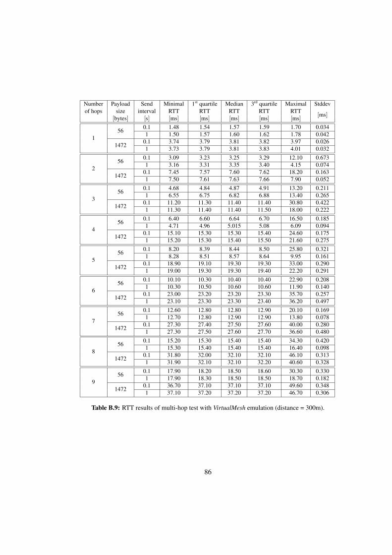
Number Payload Send Minimal 1st quartile Median 3rd quartile Maximal Stddevof hops size interval RTT RTT RTT RTT RTT
[ms][bytes] [s] [ms] [ms] [ms] [ms] [ms]
156
0.1 1.48 1.54 1.57 1.59 1.70 0.0341 1.50 1.57 1.60 1.62 1.78 0.042
14720.1 3.74 3.79 3.81 3.82 3.97 0.0261 3.73 3.79 3.81 3.83 4.01 0.032
256
0.1 3.09 3.23 3.25 3.29 12.10 0.6731 3.16 3.31 3.35 3.40 4.15 0.074
14720.1 7.45 7.57 7.60 7.62 18.20 0.1631 7.50 7.61 7.63 7.66 7.90 0.052
356
0.1 4.68 4.84 4.87 4.91 13.20 0.2111 6.55 6.75 6.82 6.88 13.40 0.265
14720.1 11.20 11.30 11.40 11.40 30.80 0.4221 11.30 11.40 11.40 11.50 18.00 0.222
456
0.1 6.40 6.60 6.64 6.70 16.50 0.1851 4.71 4.96 5.015 5.08 6.09 0.094
14720.1 15.10 15.30 15.30 15.40 24.60 0.1751 15.20 15.30 15.40 15.50 21.60 0.275
556
0.1 8.20 8.39 8.44 8.50 25.80 0.3211 8.28 8.51 8.57 8.64 9.95 0.161
14720.1 18.90 19.10 19.30 19.30 33.00 0.2901 19.00 19.30 19.30 19.40 22.20 0.291
656
0.1 10.10 10.30 10.40 10.40 22.90 0.2081 10.30 10.50 10.60 10.60 11.90 0.140
14720.1 23.00 23.20 23.20 23.30 35.70 0.2571 23.10 23.30 23.30 23.40 36.20 0.497
756
0.1 12.60 12.80 12.80 12.90 20.10 0.1691 12.70 12.80 12.90 12.90 13.80 0.078
14720.1 27.30 27.40 27.50 27.60 40.00 0.2801 27.30 27.50 27.60 27.70 36.60 0.480
856
0.1 15.20 15.30 15.40 15.40 34.30 0.4201 15.30 15.40 15.40 15.40 16.40 0.098
14720.1 31.80 32.00 32.10 32.10 46.10 0.3131 31.90 32.10 32.10 32.20 40.60 0.328
956
0.1 17.90 18.20 18.50 18.60 30.30 0.3301 17.90 18.30 18.50 18.50 18.70 0.182
14720.1 36.70 37.10 37.10 37.10 49.60 0.3481 37.10 37.20 37.20 37.20 46.70 0.306
Table B.9: RTT results of multi-hop test with VirtualMesh emulation (distance = 300m).
86

Number Payload size Send interval Minimal 1st quartile Median 3rd quartile Maximal Stddevof nodes [bytes] [s] RTT [ms] [ms] RTT [ms] [ms] RTT [ms] [ms]
2
560.1 1.46 1.54 1.56 1.59 1.81 0.0390.5 1.48 1.56 1.59 1.61 8.53 0.1641 1.50 1.59 1.61 1.65 1.84 0.054
14720.1 3.66 3.74 3.77 3.79 4.46 0.0400.5 3.70 3.77 3.79 3.81 10.20 0.1501 3.71 3.78 3.8 3.82 5.33 0.068
3
560.1 1.47 1.55 1.56 1.59 1.83 0.0380.5 1.48 1.56 1.59 1.62 1.88 0.0521 1.49 1.59 1.61 1.65 1.83 0.051
14720.1 3.66 3.74 3.77 3.79 13.1 0.1400.5 3.71 3.77 3.79 3.81 5.96 0.0661 3.71 3.78 3.8 3.83 4.04 0.053
4
560.1 1.50 1.58 1.60 1.63 6.03 0.0710.5 1.53 1.60 1.63 1.67 4.79 0.0891 1.55 1.61 1.66 1.70 1.84 0.059
14720.1 3.71 3.77 3.79 3.81 10.10 0.1110.5 3.71 3.78 3.80 3.85 4.26 0.0531 3.72 3.79 3.82 3.87 4.36 0.064
5
560.1 1.53 1.61 1.63 1.65 15.7 0.1760.5 1.55 1.62 1.65 1.68 4.69 0.0841 1.57 1.66 1.69 1.72 1.88 0.051
14720.1 3.74 3.81 3.83 3.85 6.46 0.0610.5 3.75 3.82 3.84 3.88 4.11 0.0551 3.75 3.82 3.85 3.92 4.11 0.064
8
560.1 1.68 1.76 1.77 1.79 8.17 0.0690.5 1.71 1.77 1.79 1.80 1.97 0.0341 1.72 1.78 1.80 1.82 1.97 0.034
14720.1 3.83 3.90 3.92 3.93 4.45 0.0300.5 3.84 3.91 3.92 3.94 8.62 0.1121 3.85 3.91 3.93 3.97 4.17 0.047
12
560.1 1.92 2.00 2.01 2.03 2.21 0.0250.5 1.95 2.01 2.03 2.05 2.32 0.0331 1.96 2.02 2.04 2.06 2.23 0.032
14720.1 4.05 4.13 4.15 4.17 6.45 0.0390.5 4.07 4.14 4.16 4.19 20.70 0.3741 4.07 4.15 4.17 4.20 4.42 0.038
Table B.10: RTT dependeny on number of hosts.
87

B.3 OMNeT++/INET Simulation Results
Node distance Payload size Send interval Minimal 1st quartile Median 3rd quartile Maximal Stddev[m] [bytes] [s] RTT [ms] [ms] RTT [ms] [ms] RTT [ms] [ms]
1
560.1 0.902 1.062 1.222 1.402 2.574 0.1930.5 0.902 1.062 1.222 1.402 2.794 0.2061 0.902 1.062 1.242 1.402 2.614 0.213
14720.1 2.962 3.122 3.282 3.462 4.634 0.1930.5 2.962 3.122 3.282 3.462 4.854 0.2061 2.962 3.122 3.302 3.462 4.674 0.213
300
560.1 0.904 1.064 1.224 1.404 2.578 0.1930.5 0.904 1.064 1.224 1.404 2.798 0.2061 0.904 1.064 1.224 1.404 2.618 0.214
14720.1 2.964 3.124 3.284 3.464 4.638 0.1930.5 2.964 3.124 3.284 3.464 4.858 0.2061 2.964 3.124 3.284 3.464 4.678 0.214
580
560.1 0.906 1.066 1.226 1.406 2.582 0.1930.5 0.906 1.066 1.226 1.406 2.802 0.2061 0.906 1.066 1.246 1.406 2.622 0.214
14720.1 2.966 3.126 3.286 3.466 4.642 0.1930.5 2.966 3.126 3.286 3.466 4.862 0.2061 2.966 3.126 3.306 3.466 4.682 0.214
Table B.11: RTT results of various distances with OMNeT++ simulation.
Send Payload Minimal 1st quartile Median 3rd quartile Maximal Stddevinterval size RTT RTT RTT RTT RTT RTT
[ms][s] [bytes] [ms] [ms] [ms] [ms] [ms]
1
56 0.904 1.064 1.244 1.404 2.618 0.214128 1.009 1.169 1.349 1.509 2.723 0.214256 1.195 1.355 1.535 1.695 2.909 0.214512 1.567 1.727 1.907 2.067 3.281 0.214768 1.940 2.100 2.280 2.440 3.654 0.2141024 2.312 2.472 2.652 2.812 4.026 0.2141280 2.684 2.844 3.024 3.184 4.399 0.2141472 2.964 3.124 3.304 3.464 4.678 0.214
Table B.12: RTT results of various packet sizes with OMNeT++ simulation (distance = 300m).
88

Stream Payload Send Minimal 1st quartile Median 3rd quartile Maximal Stddevthroughput size interval RTT RTT RTT RTT RTT RTT
[ms][KB/s] [bytes] [s] [ms] [ms] [ms] [ms] [ms]
10056 1 0.904 1.064 1.224 1.384 1.544 0.186
1472 1 2.964 3.124 3.284 3.444 3.604 0.186
20056 1 0.904 1.064 1.224 1.384 1.544 0.188
1472 1 2.964 3.124 3.284 3.444 3.604 0.188
30056 1 4.873 7.385 8.619 9.889 17.924 1.982
1472 1 6.933 9.449 10.678 12.072 19.984 2.001
40056 1 5.578 12.387 14.860 18.457 27.421 4.132
1472 1 7.637 14.422 17.302 20.718 28.777 4.215
60056 1 4.370 11.936 14.738 17.613 28.072 4.333
1472 1 6.949 14.452 17.005 19.367 31.107 3.963
90056 1 5.481 11.614 14.404 16.955 24.268 3.864
1472 1 7.055 14.351 16.788 19.531 27.183 3.756
Table B.13: RTT results of OMNeT++ simulation with concurrent network stream (distance = 300m).
Number Payload Send Minimal 1st quartile Median 3rd quartile Maximal Stddevof hops size interval RTT RTT RTT RTT RTT RTT
[ms][bytes] [s] [ms] [ms] [ms] [ms] [ms]
1 56 1 0.905 1.085 1.245 1.385 1.545 0.1842 56 1 2.409 2.849 3.049 3.289 3.769 0.3073 56 1 3.752 4.612 4.902 5.252 5.972 0.4354 56 1 5.315 6.375 6.655 7.015 8.015 0.5295 56 1 6.979 8.079 8.499 8.899 15.836 0.7516 56 1 8.362 9.862 10.302 10.722 16.975 0.8427 56 1 10.205 11.585 12.065 12.585 21.494 0.9798 56 1 11.709 13.409 13.869 14.409 24.273 1.073
Table B.14: RTT results of multi-hop test with OMNeT++ simulation (distance = 300m).
89


List of Acronyms
AODV Ad-Hoc On-Demand Distance Vector Routing 2AP Access Point 2, 42API Application Programming Interface 5, 19, 33–37,
42, 75ARP Address Resolution Protocol 26, 27, 59, 61, 69
BSD Berkley Software Distribution (Berkley Unix) 32,34
CPU Central Processing Unit 16, 20, 22, 32, 59CSMA/CA Carrier Sense Multiple Access / Collision Avoid-
ance 26, 49, 71
ESSID Extended Service Set Identifier 38, 42ET Event Time 47, 48
FPGA Field-programmable Gate Array 17, 18
GNU GNU’s Not Unix 54GUI Graphical User Interface 12
HVM Hardware Virtual Machine 23, 62, 82
IBSS Independent Basic Service Set 2ICMP Internet Control Message Protocol 60, 65, 68IEEE Institute of Electrical and Electronics Engineers
2, 12, 13, 18, 19, 21, 25, 26, 33, 38, 45, 49, 51,58, 71, 72, 74
IP Internet Protocol 1, 12, 15, 27, 29, 35, 40, 52IPC Inter-process Communication 9, 33, 42
JiST Java in Simulation Time 19
91

MAC Medium Access Control 15, 18, 25, 27, 39, 49,52, 53, 68, 75
MANET Mobile Ad-Hoc Network 2–4, 19, 21, 24–27, 31,42, 60, 73
MTU Maximum Transmission Unit 30, 36, 59–61, 78
NED Network Description (OMNeT++) 12, 45, 51NWID Network Identification 42
OLSR Optimized Link State Routing 2, 19, 22, 60OS Operating System 5, 9, 14, 19, 20, 22–24, 31–33,
35, 39, 41, 60, 73, 75, 77OSI Open System Interconnection 1
PDA Personal Digital Assistant 1POSIX Portable Operating System Interface (for Unix)
34, 42PPP Point-to-Point Protocol 12, 74PV Paravirtualization 24, 62, 82, 83
RF Radio Frequency 17RFC Request for Comments 15RTS Request to Send 26, 38, 39, 54RTT Round-Trip Time 60–70, 73
SCTP Stream Control Transmission Protocol 12, 20SQL Structured Query Language 12
TCP Transmission Control Protocol 1, 12, 19, 29, 59,66, 70, 71
UDP User Datagram Protocol 12, 28, 29, 40, 46, 59,70, 71
VIF Virtual Wireless Interface 25–27, 29, 30, 33–42,45, 52, 53, 58–60, 62, 70, 75
VLAN Virtual Local Area Network 22VM/CMS Virtual Machine/Cambridge Monitor System
(IBM) 23VMM Virtual Machine Monitor 23, 24VOIP Voice over IP 18
WE Wireless Extensions 33, 34, 41
92

WiMAX Worldwide Interoperability for Microwave Ac-cess 2, 74
WLAN Wireless Local Area Network 2, 31WMAN Wireless Metropolitan Area Network 2WMN Wireless Mesh Network 2–4, 7, 11, 13, 14, 19–
22, 25–27, 31, 50, 55, 60, 67, 69, 73, 75WSN Wireless Sensor Network 12
XML Extensible Markup Language 12
93


List of Figures
1.1 Wireless infrastructure network. . . . . . . . . . . . . . . . . . . . . . . . . . 31.2 Wireless mesh network. . . . . . . . . . . . . . . . . . . . . . . . . . . . . . . 3
2.1 Module structure in OMNeT++. . . . . . . . . . . . . . . . . . . . . . . . . . 132.2 Consideration of clock time vs. simulation time. . . . . . . . . . . . . . . . . . 162.3 Number of simulation events vs. clock time. . . . . . . . . . . . . . . . . . . . 172.4 ADAM Web interface of the node status. . . . . . . . . . . . . . . . . . . . . . 23
3.1 Subdivision of the TCP/IP network stack between the wireless node and thewireless simulation server. . . . . . . . . . . . . . . . . . . . . . . . . . . . . 26
3.2 VirtualMesh architecture with virtualized nodes, real nodes and the WlanModel. 273.3 Protocol messages used to communicate between the wireless nodes and the
WlanModel. . . . . . . . . . . . . . . . . . . . . . . . . . . . . . . . . . . . . 293.4 Message flow between wireless nodes and simulation server. . . . . . . . . . . 32
4.1 Real wireless stack vs. the wireless stack of VirtualMesh. . . . . . . . . . . . . 354.2 libvif providing application access to the VIF. . . . . . . . . . . . . . . . . . . 37
5.1 WlanModel components. . . . . . . . . . . . . . . . . . . . . . . . . . . . . . 465.2 EmulationRTScheduler state diagram. . . . . . . . . . . . . . . . . . . . . . . 475.3 Node registration at the WlanModel. . . . . . . . . . . . . . . . . . . . . . . . 535.4 Wireless traffic processing at the WlanModel. . . . . . . . . . . . . . . . . . . 545.5 Wireless parameter update at the WlanModel. . . . . . . . . . . . . . . . . . . 54
6.1 Summarized RTT results for qualifying infrastructure network delay. . . . . . . 626.2 iwconnect/emulation protocol RTT overhead with respect to payload size. . . . 636.3 iwconnect/emulation protocol RTT overhead with respect to transmission interval. 646.4 RTT with various payload sizes (distance = 300m, transmission interval = 1s). . 666.5 RTT with concurrent streams (distance = 300m, transmission interval = 1s). . . 676.6 WlanModel scalability (distance = 300m, transmission interval = 1s, payload
size = 56B). . . . . . . . . . . . . . . . . . . . . . . . . . . . . . . . . . . . . 686.7 WlanModel multi-hop behaviour (distance = 500m, transmission interval = 1s,
payload size = 56B). . . . . . . . . . . . . . . . . . . . . . . . . . . . . . . . 696.8 Parallel stream throughput results. . . . . . . . . . . . . . . . . . . . . . . . . 71
95

6.9 Multi-hop throughput results. . . . . . . . . . . . . . . . . . . . . . . . . . . . 72
96

List of Tables
1.1 Real-world vs. emulation vs. simulation test-bed. . . . . . . . . . . . . . . . . 3
2.2 Typical values for the path loss exponent β. . . . . . . . . . . . . . . . . . . . 112.3 Most important add-ons for the OMNeT++ simulation framework. . . . . . . . 122.4 ADAM mesh node components. . . . . . . . . . . . . . . . . . . . . . . . . . 22
4.1 Public virtual interface API (defined in vif.h) . . . . . . . . . . . . . . . . . . . 374.2 Supported ioctl types by libvif . . . . . . . . . . . . . . . . . . . . . . . . . . 384.3 Supported wireless-tools operations. . . . . . . . . . . . . . . . . . . . . . . . 42
6.1 Static WlanModel IEEE 802.11b configuration. . . . . . . . . . . . . . . . . . 586.2 Virtual wireless device (VIF) configuration. . . . . . . . . . . . . . . . . . . . 586.3 RTT over various distances (payload size = 56B, transmission interval = 1s). . . 64
B.1 RTT of 1 Gbps cross-link. . . . . . . . . . . . . . . . . . . . . . . . . . . . . 81B.2 RTT of 1 Gbps cross-link to PV host. . . . . . . . . . . . . . . . . . . . . . . . 82B.3 RTT of 1 Gbps cross-link to HVM host. . . . . . . . . . . . . . . . . . . . . . 82B.4 RTT of 1 Gbps cross-link via iwconnect/emulation protocol. . . . . . . . . . . 83B.5 RTT of 1 Gbps cross-link to PV host via iwconnect/emulation protocol . . . . . 83B.6 RTT results of various distances with VirtualMesh emulation. . . . . . . . . . . 84B.7 RTT results of various payload sizes with VirtualMesh emulation (distance =
300m). . . . . . . . . . . . . . . . . . . . . . . . . . . . . . . . . . . . . . . . 84B.8 RTT results of VirtualMesh emulation with concurrent network stream. . . . . . 85B.9 RTT results of multi-hop test with VirtualMesh emulation (distance = 300m). . 86B.10 RTT dependeny on number of hosts. . . . . . . . . . . . . . . . . . . . . . . . 87B.11 RTT results of various distances with OMNeT++ simulation. . . . . . . . . . . 88B.12 RTT results of various packet sizes with OMNeT++ simulation (distance = 300m). 88B.13 RTT results of OMNeT++ simulation with concurrent network stream (distance
= 300m). . . . . . . . . . . . . . . . . . . . . . . . . . . . . . . . . . . . . . . 89B.14 RTT results of multi-hop test with OMNeT++ simulation (distance = 300m). . . 89
97


Listings
4.1 vifctl user interface. . . . . . . . . . . . . . . . . . . . . . . . . . . . . . . . . 394.2 VIF configuration in /etc/network/interfaces. . . . . . . . . . . . . . . . . . . . 394.3 iwconnect user interface. . . . . . . . . . . . . . . . . . . . . . . . . . . . . . 404.4 Modifications to the standard wireless-tools library (iwlib) in order to add libvif
support . . . . . . . . . . . . . . . . . . . . . . . . . . . . . . . . . . . . . . 41A.1 WlanModel OMNeT++ configuration. . . . . . . . . . . . . . . . . . . . . . . 78A.2 Example wireless node position configuration. . . . . . . . . . . . . . . . . . . 78A.3 Xen wireless node disk configuration . . . . . . . . . . . . . . . . . . . . . . . 79
99


Bibliography
[1] M. Hauben, “History of ARPANET,” http://www.dei.isep.ipp.pt/∼acc/docs/arpa.html,2010.
[2] V. Cerf and R. Kahn, “A Protocol for Packet Network Intercommunication,” IEEE Trans.Commun., vol. 22, no. 5, pp. 637–648, May 1974.
[3] H. Zimmermann, “OSI Reference Model - The ISO Model of Architecture for Open Sys-tems Interconnection,” IEEE Trans. Commun., vol. 28, no. 4, pp. 425–432, Apr. 1980.
[4] “RFC 1122: Requirements for Internet Hosts - Communication Layers,” http://tools.ietf.org/html/rfc1122, Oct. 1989.
[5] G. Marconi, “Wireless Telegraphy,” London, England, Feb. 1899.
[6] N. Abramson, “Development of the ALOHANET,” IEEE Trans. Inform. Theory, vol. 31,no. 2, pp. 119–123, Mar. 1985.
[7] IEEE Workshop on Wireless Local Area Networks, Worcester Polytechnic Institute,Worcester, MA, USA, May 9–10 1991.
[8] I. Akyildiz and X. Wang, Wireless Mesh Networks. John Wiley & Sons, Inc., 2009, p.250.
[9] I. D. Chakeres and E. M. Belding-Royer, “AODV Routing Protocol Implementation De-sign,” in International Workshop on Wireless Ad Hoc Networking (WWAN), Tokyo, Japan,Mar. 2004.
[10] “RFC 3626: Optimized Link State Routing Protocol (OLSR),” http://tools.ietf.org/html/rfc3626, Oct. 2003.
[11] H. L. Anderson, “Metropolis, Monte Carlo and the MANIAC,” Los Alamos Science,vol. 14, pp. 96–108, 1986.
[12] N. Metropolis and S. Ulam, “The Monte Carlo Method,” Journal of the American Statis-tical Association, vol. 44, no. 247, pp. 335–341, Sept. 1949.
[13] N. Metropolis, “The Beginning of the Monte Carlo Method,” Los Alamos Science, vol. 15,pp. 125–130, 1987.
101

[14] J. Yi and D. Lilja, “Simulation of Computer Architectures: Simulators, Benchmarks,Methologies and Recommendations,” IEEE Trans. Comput., vol. 55, no. 3, pp. 268–280,Mar. 2006.
[15] J. Banks, J. Carson, B. Nelson, and D. Nicole, Discrete-Event System Simulation. Pear-son Education, June 2009.
[16] F. E. Cellier and E. Kofman, Continuous System Simulation. Springer, Mar. 2006.
[17] T. Williams, “Simulating the man-in-the-loop,” Operational Research Society, vol. 9,no. 4, pp. 17–21, Oct. 1996.
[18] M. Gomez, “Hardware-in-the-Loop Simulation,” Embedded Systems Design, Nov. 1991,http://www.embedded.com/design/15201692.
[19] J. Liu, Y. Yuan, D. Nicol, R. Gray, C. Newport, D. Kotz, and L. F. Perrone, “Simula-tion Validation Using Direct Execution of Wireless Ad-Hoc Routing Protocols,” in 18thWorkshop on Parallel and Distributed Simulation, Kufstein, Austria, May 16–19 2004,pp. 7–16.
[20] C. P. Mayer and T. Gamer, “Integrating real world applications into OMNeT++,” Instituteof Telematics, University of Karlsruhe, Tech Report TM-2008-2, Feb. 27 2008.
[21] R. L. Freeman, Fundamentals of Telecommunications, 2nd ed. Hoboken, New Jersey,USA: John Wiley & Sons, Inc., 2005.
[22] H. T. Friis, “A Note on a Simple Transmission Formula,” in Proceedings of the I.R.E. andWaves and Electrons, vol. 34, no. 5, May 1946, pp. 254–256.
[23] D. R. Smith, Digital Transmission Systems. Norwell, Massachusetts, USA: KluwerAcademic Publishers, 1993.
[24] B. Sklar, “Rayleigh Fading Channels in Mobile Digital Communication Systems Part I:Characterization,” IEEE Commun. Mag., vol. 35, no. 7, pp. 90–100, July 1997.
[25] M. M. Carvalho and J. J. Garcia-Luna-Aceves, “Modeling Single-Hop Wireless Networksunder Rician Fading Channels,” in 5th IEEE Wireless Communications and NetworkingConference (WCNC ’04), vol. 4, March 21-25 2004, pp. 219–224.
[26] T. S. Rappaport, Wireless Communications, Principles and Practice, 2nd ed. PrenticeHall, 2001.
[27] T. Henderson, The Network Simulator ns-2 Documentation, 2010.
[28] C.-M. Cheng, P.-H. Hsiao, H. Kung, and D. Vlah, “Adjacent Channel Interference inDual-radio 802.11a Nodes and Its Impact on Multi-hop Networking,” in IEEE GLOBE-COM 2006, San Francisco, CA, USA, 27 November - 1 December 2006.
102

[29] V. Angelakis, S. Papadakis, N. Kossifidis, V. A. Siris, and A. Traganiti, “The Effect ofUsing Directional Antennas on Adjacent Channel Interference in 802.11a: Modeling andExperience With an Outdoors Testbed,” in 4th International Workshop on Wireless Net-work Measurements (WiNMee ’08), Mar. 2008.
[30] J. Nachtigall, A. Zubow, and J.-P. Redlich, “The Impact of Adjacent Channel Interferencein Multi-Radio Systems using IEEE 802.11,” in Wireless Communications and MobileComputing Conference (IWCMC ’08), August 6-8 2008, pp. 874–881.
[31] D. Kotz, C. Newport, R. S. Gray, J. Liu, Y. Yuan, and C. Elliott, “Experimental Evaluationof Wireless Simulation Assumptions,” in 7th ACM International Symposium on Modeling,Analysis and Simulation of Wireless and Mobile Systems (MSWiM ’04). New York, NY,USA: ACM, 2004, pp. 78–82.
[32] J. Liu, Y. Yuan, D. M. Nicol, R. S. Gray, C. C. Newport, D. Kotz, and L. F. Perrone,“Empirical Validation of Wireless Models in Simulations of Ad Hoc Routing Protocols,”Simulation, vol. 81, no. 4, pp. 307–323, 2005.
[33] A. Varga and R. Hornig, “An overview of the OMNeT++ simulation environment,” in 1stInternational Conference on Simulation Tools and Techniques for Communications, Net-works and Systems (Simutools ’08). ICST, Brussels, Belgium, Belgium: ICST (Institutefor Computer Sciences, Social-Informatics and Telecommunications Engineering), 2008,pp. 1–10.
[34] “3rd International Workshop on OMNeT++,” http://www.omnet-workshop.org/2010,March 19 2010.
[35] “Tk, the Graphical User Interface Toolkit,” http://www.tkdocs.com/, 2010.
[36] M. Bredel and M. Bergner, “On The Accuracy of IEEE 802.11g Wireless LAN Simu-lations Using OMNet++,” in 2nd International Workshop on OMNeT++. ICST, Brus-sels, Belgium, Belgium: ICST (Institute for Computer Sciences, Social-Informatics andTelecommunications Engineering), 2009.
[37] S. Woon, E. Wu, and A. Sekercioglu, “A Simulation Model of IEEE802.11b for Per-formance Analysis of Wireless LAN Protocols,” in Australian Telecommunications, Net-works and Applications Conference (ATNAC ’03), 2003.
[38] A. Kuntz, F. Schmidt-Eisenlohr, O. Graute, H. Hartenstein, and M. Zitterbart, “Introduc-ing probabilistic radio propagation models in OMNeT++ mobility framework and crossvalidation check with NS-2,” in 1st International Conference on Simulation Tools andTechniques for Communications, Networks and Systems (Simutools ’08). ICST, Brus-sels, Belgium, Belgium: ICST (Institute for Computer Sciences, Social-Informatics andTelecommunications Engineering), 2008, pp. 1–7.
[39] J.-C. Maureiraand, D. Dujovne, and O. Dalle, “Generation of Realistic 802.11 Interfer-ences in the Omnet++ INET Framework Based on Real Traffic Measurements,” in 2nd
103
International Workshop on OMNeT++. Brussels, Belgium: ICST (Institute for Com-puter Sciences, Social-Informatics and Telecommunications Engineering), 2009.
[40] T. Braun, M. Diaz, J. Enrıquez-Gabeiras, and T. Staub, End-to-End Quality of ServiceOver Heterogeneous Networks. Springer, Feb. 2008.
[41] G. Judd and P. Steenkiste, “Repeatable and Realistic Wireless Experimentation throughPhysical Emulation,” in 2nd Workshop on Hot Topics in Networks (Hot-Nets II), Nov.2003.
[42] K. C. Borries, G. Judd, D. D. Stancil, and P. Steenkiste, “FPGA-Based Channel Simu-lator for a Wireless Network Emulator,” in 67th IEEE Vehicular Technology Conference(VTC2009-Spring), Apr. 2009.
[43] T. Perennou, E. Conchon, L. Dairaine, and M. Diaz, “Two-Stage Wireless NetworkEmulation,” in IFIP World Computer Congress - Workshop on Challenges of Mobility,Toulouse, France, Aug. 22–27 2004.
[44] R. Beuran, L. T. Nguyen, K. T. Latt, J. Nakata, and Y. Shinoda, “QOMET: A VersatileWLAN Emulator,” 21st International Conference on Advanced Information Networkingand Applications (AINA ’07), vol. 0, pp. 348–353, 2007.
[45] R. Beuran, J. Nakata, T. Okada, L. T. Nguyen, Y. Tan, and Y. Shinoda, “A Multi-purposeWireless Network Emulator: QOMET,” in 22nd International Conference on AdvancedInformation Networking and Applications (AINA ’08), 2008, pp. 223–228.
[46] L. Rizzo, “Dummynet: A simple Approach to the Evaluation of Network Protocols,”SIGCOMM Comput. Commun. Rev., vol. 27, no. 1, pp. 31–41, 1997.
[47] T. Krop, M. Bredel, M. Hollick, and R. Steinmetz, “JiST/MobNet: Combined Simulation,Emulation, and Real-World Testbed for Ad Hoc Networks,” in 2nd ACM InternationalWorkshop on Wireless Network Testbeds, Experimental Evaluation and Characterization(WinTECH), New York, NY, USA, Sep. 10 2007, pp. 27–34.
[48] R. Barr, Z. Haas, and R. van Renesse, “JiST: An efficient approach to simulation usingvirtual machine,” Software – Practice & Experience, vol. 35, no. 6, pp. 539–576, 2004.
[49] B. White, J. Lepreau, L. Stoller, R. Ricci, S. Guruprasad, M. Newbold, M. Hibler, C. Barb,and A. Joglekar, “An integrated Experimental Environment for Distributed Systems andNetworks,” SIGOPS Oper. Syst. Rev., vol. 36, no. SI, pp. 255–270, 2002.
[50] B. White, J. Lepreau, and S. Guruprasad, “Lowering the barrier to wireless and mobileexperimentation,” SIGCOMM Comput. Commun. Rev., vol. 33, no. 1, pp. 47–52, 2003.
[51] D. Johnson, T. Stack, R. Fish, D. M. Flickinger, L. Stoller, R. Ricci, and J. Lepreau,“Mobile Emulab: A Robotic Wireless and Sensor Network Testbed,” in 25th IEEE In-ternational Conference on Computer Communications (INFOCOM ’06), Apr. 2006, pp.1–12.
104

[52] S. R. Doshi, U. Lee, and R. L. Bagrodia, “Wireless Network Testing and Evaluation usingReal-time Emulation,” ITEA Journal, vol. 28, no. 2, Jun/July 2007.
[53] “Scalable Network Technologies, QualNet Network Simulator,” http://qualnet.com/,2010.
[54] “The Network Simulator - ns-2,” http://www.isi.edu/nsnam/ns/, 2010.
[55] M. Shen and D. Zhao, “TCP Throughput Performance in IEEE 802.11-based Multi-hopWireless Networks,” in 3rd International Conference on Quality of Service in Heteroge-neous Wired/Wireless Networks (QShine ’06). New York, NY, USA: ACM, 2006, p. 23.
[56] Y. Xue, H. S. Lee, M. Yang, P. Kumarawadu, H. Ghenniwa, and W. Shen, “PerformanceEvaluation of ns-2 Simulator for Wireless Sensor Networks,” in Canadian Conference onElectrical and Computer Engineering (CCECE ’07), Apr. 2007, pp. 1372–1375.
[57] M. Takai, J. Martin, and R. Bagrodia, “Effects of Wireless Physical Layer Modeling inMobile Ad Hoc Networks,” in 2nd ACM international Symposium on Mobile Ad HocNetworking & Computing (MobiHoc ’01), 2001, pp. 87–94.
[58] D. Mahrenholz and S. Ivanov, “Real-Time Network Emulation with ns-2,” in 8th IEEEInternational Symposium on Distributed Simulation and Real-Time Applications, Oct.21–23 2004, pp. 29–36.
[59] ——, “Adjusting the ns-2 Emulation Mode to a Live Network,” in 14th GI/ITG Confer-ence on Kommunikation in Verteilten Systemen (KiVS ’05), Mar. 2005.
[60] S. Ivanov, A. Herms, and G. Lukas, “Experimental Validation of the ns-2 Wireless Modelusing Simulation, Emulation, and Real Network,” in 4th Workshop on Mobile Ad-HocNetworks, Bern, Switzerland, Feb. 2 – Mar. 2 2007, pp. 433–444.
[61] M. Lacage, M. Weigle, C. Dowell, G. Carneiro, G. Riley, T. Henderson, and J. Pelkey,“The ns-3 Network Simulator,” http://www.nsnam.org/, 2010.
[62] M. Tuxen, I. Rungeler, and E. P. Rathgeb, “Interface connecting the INET simulationframework with the real world,” in 1st International Conference on Simulation Tools andTechniques for Communications, Networks and Systems (Simutools ’08). ICST, Brus-sels, Belgium, Belgium: ICST (Institute for Computer Sciences, Social-Informatics andTelecommunications Engineering), 2008, pp. 1–6.
[63] D. Balsiger, “Administration and Development of Wireless Mesh Networks,” Master’sthesis, University of Bern, Institute of Computer Science and Applied Mathematics, 2009.
[64] A. Zimmermann, M. Gunes, M. Wenig, U. Meis, and J. Ritzerfeld, “How to study Wire-less Mesh Networks: A hybrid Testbed Approach,” in 21st IEEE International Confer-ence on Advanced Information Networking and Applications (AINA ’07), May 2007, pp.853–860.
105

[65] “ORBIT: A laboratory emulator/field trial network testbed,” http://www.orbit-lab.org/,WINLAB, Rutgers University, New Jersey, USA, 2010.
[66] D. Raychaudhuri, I. Seskar, M. Ott, S. Ganu, K. Ramachandran, H. Kremo, R. Siracusa,H. Liu, and M. Singh, “Overview of the ORBIT Radio Grid Testbed for Evaluation ofNext-Generation Wireless Network Protocols,” in IEEE Wireless Communications andNetworking Conference (WCNC ’05), vol. 3, Mar. 2005, pp. 1664–1669.
[67] “OneLab - Future Internet Test Beds,” http://www.onelab.eu/, 2010.
[68] B. Mathieu, D.-E. Meddour, F. Jan, Y. Gourhant, M. Pilarski, and P. Zdroik, “OneLabWireless Mesh Multi-hop Network,” OneLab, Deliverable D4D1 IST-4-034819-OneLab-XXX, Aug. 2007.
[69] A.-C. Anadiotis, A. Apostolaras, D. Giatsios, T. Korakis, D. Syrivelis, L. Tassiulas,S. Avallone, A. Botta, R. Canonico, G. D. Stasi, Y. Lopez, O. Marce, A. Cimmino,P. Donadio, and P. Benko, “OneLab2 Wireless Testbeds,” OneLab,” Deliverable D6.1,Sept. 2009.
[70] “NITOS: Network Implementation Testbed using Open Source code,” http://nitlab.inf.uth.gr/NITlab/index.php/testbed.html, 2010.
[71] D. Balsiger and M. Lustenberger, “Secure Remote Management and Software Distribu-tion for Wireless Mesh Networks,” Sept. 2007, Computer Science Project, University ofBern.
[72] S. Morgenthaler, “Management Extensions for Wireless Mesh and Wireless Sensor Net-works,” 2010, Bachelor Thesis, University of Bern.
[73] “PC Engines ALIX System Boards,” http://www.pcengines.ch/alix.htm, 2010.
[74] “Meraki: Wireless Networks that Simply Work,” http://meraki.com/, 2010.
[75] “Neo FreeRunner,” http://wiki.openmoko.org/wiki/Neo FreeRunner, 2010.
[76] T. Staub, S. Ott, and T. Braun, “Experimental Evaluation of Multi-Path Routing in aWireless Mesh Network Inside a Building,” in 5th Workshop on Mobile Ad-Hoc Networks(WMAN 2009) in conjunction with the 16th bi-annual Conference on Communication inDistributed Systems (KiVS), vol. 17. Electronic Communications of the EASST, March5-6 2009, pp. 1–12.
[77] T. Staub, M. Brogle, K. Baumann, and T. Braun, “Wireless Mesh Networks for Intercon-nection of Remote Sites to Fixed Broadband Networks,” in Third ERCIM Workshop oneMobility. University of Twente, Eschede, May 27-28 2009, pp. 97–98.
[78] Sun Microsystems, “Java Virtual Machine,” http://java.sun.com/docs/books/jvms/, 2010.
[79] Microsoft, “Microsoft .NET Common Language Runtime,” http://msdn.microsoft.com/en-us/library/8bs2ecf4.aspx, 2010.
106

[80] T. V. Vleck, “The IBM 360/67 and CP/CMS,” http://www.multicians.org/thvv/360-67.html, Apr. 2009.
[81] J. Dike, “User-mode Linux,” in 5th Linux Showcase & Conference (ALS ’01). Berkeley,CA, USA: USENIX Association, 2001, pp. 2–2.
[82] ——, “The User-mode Linux Kernel,” http://user-mode-linux.sourceforge.net/, 2010.
[83] S. Maier, A. Grau, H. Weinschrott, and K. Rothermel, “Scalable Network Emulation:A Comparison of Virtual Routing and Virtual Machines,” in 12th IEEE Symposium onComputers and Communications (ISCC ’07), 2007.
[84] Walter M. Fuertes and Jorge E. Lopez de Vergara, “A Quantitative Comparison of VirtualNetwork Environments Based on Performance Measurements,” July 2007, 14th Work-shop of the HP Software University Association.
[85] S. Singhal, G. Hadjichristofi1, I. Seskar1, and D. Raychaudhri1, “Evaluation of UMLBased Wireless Network Virtualization,” in 4th Euro-NGI Conference on Next GenerationInternet Networks (NGI ’08), April 28-30 2008.
[86] “VMware ESX Hypervisor,” http://www.vmware.com/products/esx/, 2010.
[87] P. Barham, B. Dragovic, K. Fraser, S. Hand, and T. Harris, “Xen and the Art of Virtu-alization,” in 9th ACM Symposium on Operating Systems Principles (SOSP ’03), BoltonLanding, NY, USA, October 19–22 2003.
[88] “Virtualbox,” http://www.virtualbox.org/, 2010.
[89] “Kernel Based Virtual Machine (KVM),” http://www.linux-kvm.org/, 2010.
[90] VMware Inc., “Understanding Full Virtualization, Paravirtualization, and HardwareAssist,” http://www.vmware.com/files/pdf/VMware paravirtualization.pdf, Sept. 2009,White Paper.
[91] M. Engel, M. Smith, S. Hanemann, and B. Freisleben, “Wireless Ad-Hoc Network Em-ulation using Microkernel-based Virtual Linux Systems,” in 5th EUROSIM Congress onModeling and Simulation, Sep. 6–10 2004, pp. 198–203.
[92] H. Hartig, M. Hohmuth, J. Liedtke, S. Schonberg, and J. Wolter, “The Performance ofµ-Kernel-Based Systems,” in 16th ACM Symposium on Operating Systems Principles(SOSP ’97), Oct. 1997.
[93] Y. Zhang and W. Li, “An Integrated Environment for testing Mobile Ad-Hoc Networks,”in 3rd ACM International Symposium on Mobile Ad Hoc Networking Computing (Mobi-Hoc), 2002, pp. 104–111.
[94] D. Gupta, K. Yocum, M. McNett, A. C. Snoeren, A. Vahdat, and G. M. Voelker, “ToInfinity and Beyond: Time-Warped Network Emulation,” in 3rd ACM Symposium onNetworked Systems Design Implementation, May 2006.
107

[95] E. Weingartner, F. Schmidt, T. Heer, and K. Wehrle, “Synchronized Network Emula-tion: Matching Prototypes with Complex Simulations,” ACM SIGMETRICS PerformanceEvaluation Review, vol. 36, no. 2, pp. 58–63, 2008.
[96] E. Weingartner, “[Ns-developers] Coming up: Synchronized Network Emulation for ns-3,” http://mailman.isi.edu/pipermail/ns-developers/2009-July/006198.html, July 2009.
[97] T. Staub, R. Gantenbein, and T. Braun, “VirtualMesh: An Emulation Framework forWireless Mesh Networks in OMNeT++,” in The 2nd International Workshop on OM-NeT++ (OMNeT++ 2009) held in conjuction with the 2nd International Conferenceon Simulation Tools and Techniques. ICST (Institute for Computer Sciences, Social-Informatics and Telecommunications Engineering), March 6-7 2009, pp. 1–8.
[98] ——, “VirtualMesh: An Emulation Framework for Wireless Mesh and Ad-Hoc Networksin OMNeT++,” SIMULATION: Transactions of the Society for Modeling and SimulationInternational, 2010, Special Issue on Software Tools, Techniques and Architectures forComputer Simulation.
[99] “RFC 826: An Ethernet Address Resolution Protocol,” http://tools.ietf.org/html/rfc826,Nov. 1982.
[100] A. Varga and R. Hornig, “OMNeT++: An extensible, modular, component-based C++simulation library and framework,” http://www.omnetpp.org/, 2010.
[101] R. Hornig, “INET Framework for OMNeT++,” http://inet.omnetpp.org/, 2010.
[102] K. Wessel, M. Swigulski, A. Kupke, and D. Willkomm, “MiXiM (mixed simulator): Asimulation framework for wireless and mobile networks,” http://mixim.sourceforge.net/,2010.
[103] H. A. Council, “Interconnect Analysis: 10GigE and InfiniBand in High Perfor-mance Computing,” http://www.hpcadvisorycouncil.com/pdf/IB and 10GigE in HPC.pdf, 2009, White Paper.
[104] A. M. Mukwevho, J. A. van der Poll, and R. M. Jolliffe, “A virtual integrated networkemulator on XEN (viNEX),” in 2nd International Conference on Simulation Tools andTechniques (Simutools ’09), 2009, pp. 1–7.
[105] P. D. Gennaro, R. Bifulco, and R. Canonico, “Link Multiplexing in a Xen-based Net-work Emulation System,” in 6th International Workshop on Next Generation NetworkingMiddleware (NGNM ’09), Oct 26-30 2009.
[106] R. Canonico, P. D. Gennaro, V. Manetti, and G. Ventre, “Virtualization Techniques inNetwork Emulation Systems,” in Proceedings of the International Euro-Par Workshops2007. Springer, November 2007.
[107] J. Tourrilhes, “Wireless Extensions: A Wireless LAN API for the Linux Oper-ating System,” http://www.hpl.hp.com/personal/Jean Tourrilhes/Linux/Linux.Wireless.Extensions.html, 2010.
108

[108] “The Madwifi Project,” http://madwifi-project.org/, 2010.
[109] J. Tourrilhes, “Wireless Tools for Linux,” http://www.hpl.hp.com/personal/JeanTourrilhes/Linux/Tools.html, 2010.
[110] J. Malinen, “Linux WPA/WPA2/IEEE 802.1X Supplicant,” http://hostap.epitest.fi/wpasupplicant/, 2010.
[111] “nl80211: The new 802.11 Netlink Interface,” http://wireless.kernel.org/en/developers/Documentation/nl80211, 2010.
[112] J. Berg, “iw: CLI configuration utility for wireless devices,” http://wireless.kernel.org/en/users/Documentation/iw, 2010.
[113] K. K. He, “Why and How to Use Netlink Socket,” Linux Journal, Jan. 2005, http://www.linuxjournal.com/article/7356.
[114] P. Mochel, “The sysfs Filesystem,” in Proceedings of the 2005 Linux Symposium, July2005.
[115] M. Krasnyansky and F. Thiel, Universal TUN/TAP device driver, 2002.
[116] B. Eckenfels and P. Blundell, “Linux net-tools,” http://net-tools.berlios.de/, 2010.
[117] A. Kuznetsov and S. Hemminger, “Linux iproute2,” http://www.linuxfoundation.org/collaborate/workgroups/networking/iproute2, 2010.
[118] P. Kyasanur, C. Chereddi, and N. H. Vaidya, “Net-X: System eXtensions for SupportingMultiple Channels, Multiple Interfaces, and other Interface Capabilities,” University ofIllinois at Urbana-Champaign, Urbana, IL, USA, Tech Report, Aug. 2006.
[119] J.-P. Ebert and A. Willig, “A Gilbert-Elliot Bit Error Model and the Efficient Use in PacketLevel Simulation,” Technical University Berlin, Telecommunication Networks Group,TKN Technical Report TKN-99-02, Mar. 1999.
[120] H. Hellbruck, “Ad-Hoc Network Simulation,” http://www.ansim.info/, 2006.
[121] M. Gerharz and C. de Waal, “BonnMotion: A mobility scenario generation and analysistool,” http://net.cs.uni-bonn.de/wg/cs/applications/bonnmotion/, 2010.
[122] Free Software Foundation, Inc., “GNU Binutils,” http://www.gnu.org/software/binutils/,2010.
[123] “GNU GRUB - A Multiboot boot loader,” http://www.gnu.org/software/grub/, 2010.
[124] T. Staub, D. Balsiger, M. Lustenberger, and T. Braun, “Secure Remote Management andSoftware Distribution for Wireless Mesh Networks,” in 7th International Workshop onApplications and Services in Wireless Networks (ASWN ’07), May 24-26 2007, pp. 47–54.
109
[125] M. Burgess and R. Ralston, “Strategies for Distributed Resource Administration UsingCfengine,” Software-Practice and Experience, vol. 27, pp. 1067–1081, Sept. 1997.
[126] J. Katz, “pyGrub,” http://wiki.xensource.com/xenwiki/PyGrub, 2010.
[127] “olsrd - An ad-hoc wireless mesh routing daemon,” http://www.olsr.org/, 2010.
[128] A. Kuznetsov and Y. Hideaki, “Linux iputils,” http://www.linuxfoundation.org/collaborate/workgroups/networking/iputils, 2010.
[129] “Tcpdump/Libpcap Public Repository,” http://www.tcpdump.org/, 2010.
[130] D. Stenberg, “curl,” http://curl.haxx.se/, 2010.
[131] “netperf - Network Performance Benchmark,” http://www.netperf.org/, 2010.
110