viscoelasticity of axisymmetric composite structures ... · accounts for ply-by-ply variation of...
TRANSCRIPT

Viscoelasticity of Axisymmetric Composite Structures:
Analysis and Experimental Validation
by Jerome T. Tzeng, Ryan P. Emerson, and Daniel J. O’Brien
ARL-TR-6317 February 2013 Approved for public release; distribution is unlimited.

NOTICES
Disclaimers The findings in this report are not to be construed as an official Department of the Army position unless so designated by other authorized documents. Citation of manufacturer’s or trade names does not constitute an official endorsement or approval of the use thereof. Destroy this report when it is no longer needed. Do not return it to the originator.

Army Research Laboratory Aberdeen Proving Ground, MD 21005-5069
ARL-TR-6317 February 2013
Viscoelasticity of Axisymmetric Composite Structures: Analysis and Experimental Validation
Jerome T. Tzeng, Ryan P. Emerson, and Daniel J. O’Brien
Weapons and Materials Research Directorate, ARL Approved for public release; distribution is unlimited.

ii
REPORT DOCUMENTATION PAGE Form Approved OMB No. 0704-0188
Public reporting burden for this collection of information is estimated to average 1 hour per response, including the time for reviewing instructions, searching existing data sources, gathering and maintaining the data needed, and completing and reviewing the collection information. Send comments regarding this burden estimate or any other aspect of this collection of information, including suggestions for reducing the burden, to Department of Defense, Washington Headquarters Services, Directorate for Information Operations and Reports (0704-0188), 1215 Jefferson Davis Highway, Suite 1204, Arlington, VA 22202-4302. Respondents should be aware that notwithstanding any other provision of law, no person shall be subject to any penalty for failing to comply with a collection of information if it does not display a currently valid OMB control number. PLEASE DO NOT RETURN YOUR FORM TO THE ABOVE ADDRESS.
1. REPORT DATE (DD-MM-YYYY)
February 2013 2. REPORT TYPE
Final 3. DATES COVERED (From - To)
May 2012 4. TITLE AND SUBTITLE
Viscoelasticity of Axisymmetric Composite Structures: Analysis and Experimental Validation
5a. CONTRACT NUMBER
5b. GRANT NUMBER
5c. PROGRAM ELEMENT NUMBER
6. AUTHOR(S)
Jerome T. Tzeng, Ryan P. Emerson, and Daniel J. O’Brien 5d. PROJECT NUMBER
5e. TASK NUMBER
5f. WORK UNIT NUMBER
7. PERFORMING ORGANIZATION NAME(S) AND ADDRESS(ES)
U.S. Army Research Laboratory ATTN: RDRL-WMM-A Aberdeen Proving Ground, MD 21005-5069
8. PERFORMING ORGANIZATION REPORT NUMBER
ARL-TR-6317
9. SPONSORING/MONITORING AGENCY NAME(S) AND ADDRESS(ES)
10. SPONSOR/MONITOR’S ACRONYM(S)
11. SPONSOR/MONITOR'S REPORT NUMBER(S)
12. DISTRIBUTION/AVAILABILITY STATEMENT
Approved for public release; distribution is unlimited.
13. SUPPLEMENTARY NOTES
14. ABSTRACT
Stress relaxation and creep of composite cylinders are investigated based on anisotropic viscoelasticity. The analysis accounts for ply-by-ply variation of material properties, ply orientations, and temperature gradients through the thickness of cylinders subjected to mechanical and thermal loads. Experimental validation of the model is conducted using a high-tensioned composite overwrapped on a steel cylinder. The creep and stress relaxation response of composite is accelerated at elevated temperatures, then characterized and compared with the model simulation. Fiber-reinforced composite materials generally illustrate extreme anisotropy in viscoelastic behavior. Accordingly, viscoelastic characteristics of composite cylinders are quite different from those of isotropic cylinders. Viscoelastic effects of the composite can result in a drastic change of stress and strain profiles in the cylinders over a period of time, which is critical for structural durability of composite cylinders. The developed analysis can be applied to composite pressure vessels, gun barrels, and flywheels.
15. SUBJECT TERMS
viscoelasticity, creep, composite, gun barrel, flywheel
16. SECURITY CLASSIFICATION OF: 17. LIMITATION OF ABSTRACT
UU
18. NUMBER OF PAGES
28
19a. NAME OF RESPONSIBLE PERSON
Jerome T. Tzeng a. REPORT
Unclassified b. ABSTRACT
Unclassified c. THIS PAGE
Unclassified 19b. TELEPHONE NUMBER (Include area code)
410-306-0959 Standard Form 298 (Rev. 8/98)
Prescribed by ANSI Std. Z39.18
iii
Contents
List of Figures iv
1. Introduction 1
2. Viscoelastic Formulation 2
3. Experimental Validation 7
4. Relaxation of Thermal Stresses 12
5. Relaxation of Mechanical Stresses 14
6. Conclusions 16
7. References 17
Distribution List 19

iv
List of Figures
Figure 1. Cylindrical coordinate system (r,, z) is used to derive the governing equations for the laminated composite cylinder. Radial displacement and stress continuity conditions are imposed to obtain the multilayered cylinder solution. .........................................................4
Figure 2. Illustration of parent tube and ring specimen. .................................................................8
Figure 3. Results from ring relaxation experiment. ........................................................................9
Figure 4. Master curves of creep compliance and time-temperature superposition. ....................10
Figure 5. Radial-stress profile prediction and a comparison to the ring relaxation experiment. ..11
Figure 6. Hoop-stress profile prediction of the ring experiment. .................................................11
Figure 7. Radial-displacement profiles in a cylinder subjected to thermal loads. ........................13
Figure 8. Radial-stress profiles in a cylinder subjected to thermal loads. ....................................13
Figure 9. Hoop-stress profiles in a cylinder subjected to thermal loads. ......................................14
Figure 10. Radial-displacement profiles in a cylinder subjected to internal pressure. .................15
Figure 11. Radial-stress profiles in a cylinder subjected to internal pressure. .............................15
Figure 12. Hoop-stress profiles in a cylinder subjected to internal pressure. ...............................16

1
1. Introduction
Composite materials are currently used for lightweight pressure vessels and highly efficient rotors for energy storage. For both applications, pre-stresses are built in during fabrication of the cylinders through a “press-fit” procedure to enhance the mechanical performance. For pressure vessels, this pre-stress is achieved by pressurizing the vessel’s interior liner prior to winding the composite overwrap. Therefore, after manufacturing, the liner is in a state of hoop compression and the composite overwrap is in tension. For the rotor application, the rotors are subjected to a radial compression prior to operation. Accordingly, the centrifugal force resulting from the rotation of the rotors generates tensile stresses in the radial and circumferential directions. Since the composite rotors are mainly circumferentially reinforced (filament-wound cylinders), the radial tensile stress is critical to the ultimate performance of the rotors. It is essential, then, to design and build the rotors with radial precompression. However, polymer matrix composites generally creep over a long period of time, especially at an elevated temperature (1). The associated stress relaxation in the composite will result in the loss of the pre-stresses and lead to a potential failure. The objective of this investigation is to develop an analytical method to study the viscoelastic behavior of thick-walled composite cylinders. The analysis can be applied to the design of flywheel machinery and composite pressure vessels.
To date, activities in the research of viscoelasticity have mainly concerned isotropic materials, including studies by Muki and Sternberg (2), Schapery (3), Williams (4), and Christensen (5). These basic theories of viscoelasticity were then extended to the area of heterogeneous and anisotropic materials for a variety of applications. Hashin (6) used the effective relaxation moduli and creep compliances to define the macroscopic viscoelastic behavior of linear viscoelastic heterogeneous media and its implementation in viscoelastic modeling. Schapery (7) examined the applications of the correspondence principle and the general formulation of linear viscoelastic boundary value problems of composite materials, including the thermal viscoelastic problems for thermorheologically simple materials.. Rogers and Lee (8) investigated the viscoelastic behavior of an isotropic cylinder. Tzeng and Chien (9) used a multiscale modeling modeling technique to study heterogenous viscoelastic solids containing evolving cracks. In addition, finite element packages, such as ABAQUS, ANSYS, and DYNA3D, are not suitable for the viscoelastic analysis of composite cylinders because of the lack of anisotropic viscoelastic elements. A viscoelastic analysis was proposed by Chien and Tzeng (10) to solve thermal stress relaxation in an anisotropic-laminated composite cylinder. Souza and Allen (11) used a multiscaled modeling technique for solving viscoelastic solid with microcracks. An extensive review on viscoelastic solids by Wineman (12) illustrated the recent progress in this particular field.

2
2. Viscoelastic Formulation
The following research studied the quasistatic viscoelastic behavior of the liner in a thick-laminated composite cylinder with thermal stress caused by an elevated temperature change. Accordingly, the field temperature is constant. The analysis accounts for ply-by-ply variation of properties, temperature changes, and fiber orientations. The thick cylinder is assumed to be in the absence of thermomechanical coupling and in a state of generalized plane strain where all stress and strain components are independent of the axial coordinate (9, 10). Moreover, due to the nature of axisymmetry, all stress and strain components are also independent of the circumferential coordinate. The mechanical responses of this thick composite cylinder will, therefore, have to satisfy only the governing equation in the radial direction. Invoking the Boltzmann superposition integral for the complete spectrum of increments of anisotropic material constants with respect to time, the thermoviscoelastic constitutive relations of the anisotropic composite cylinder can be derived in integral forms. Since the thick composite cylinder is subjected to a constant elevated temperature and boundary conditions are all independent of time, formulations of the linear thermal viscoelastic problem can have forms identical to those of the corresponding linear thermoelastic problem by taking advantage of the elastic-viscoelastic correspondence principle. In other words, all of these integral constitutive equations reduce to the algebraic relations, which are very similar to those developed for thermoelastic media when they are Laplace-transformed by means of the rule for convolution integrals. The thermoelastic analysis can thus be used to derive the transformed thermal viscoelastic solutions in the frequency domain.
The Boltzmann superposition integral of stress, ij (i, j = 1, 2, 3), and strain, ij (i, j = 1, 2, 3), relation for an isothermal viscoelastic problem with a constant temperature increases T, and the thermal expansion coefficient kl(T) is
, (1)
where is the relaxation modulus dependent on temperature T and time t,
(2)
and
. (3)
ij 0
tijkl kl
ij(t) = C (T,t - ) ( )
d - (T,t) T
ijklC (T,t)
ijkl
ijkl
0C (T(t),t) = C ( T , (t))
T
(t) = t
a (T(t)),

3
Here, T0 is the base temperature and aT is the temperature shift factor. ij(T,t) is given by ij(T,t) = Cij
kl(T,t)kl(T). It is often desirable to use the inverse form of the constitutive relation in equation 1,
, (4)
where ij(T,t) is the tensor product of the creep compliance and the thermal creep
coefficient . Since the elevated temperature change T is constant above some reference
value in time, the relaxation moduli and creep compliance are evaluated at that reference temperature, regardless of whether or not the material is thermorheologically simple, by employing the temperature shift-factor.
The Laplace transform of a function f(t) is defined as
, (5)
where s is the Laplace transform variable. Accordingly, the temperature is considered as a constant. Applying equation 3 with the convolution rule to equations 1 and 2 reduces the integral constitutive equations to the following algebraic relations:
(6)
and the inverse form
, (7)
respectively, where
, (8)
and
(9)
Furthermore, it can be shown that
. (10)
Consider a filament-wound, axisymmetric, thick composite cylinder consisting of N layers with the axial coordinate z, the radial coordinate r, and the circumferential coordinate , as shown in figure 1. The composite cylinder has the inner radius a, the outer radius b, and the length L. There is, therefore, a corresponding thermoelastic problem with the transformed displacement
ij 0
tijkl kl
ij(t) = A (T,t - )( )
d + (T,t) T
ijklA (T,t)
kl
f = f (s) = e f(t)dt 0-st
ij ijkl
kl ij = C -
T
s
~ ~ ~
~ ~ ~ ij ijkl
ij ij = A + T
s
~ ~ ~ ~ ~ ~ ~C = s C , A = s A , = s , = s , = C ijkl
ijkl
ijkl
ijkl
ij ij ij ij kl ijkl
ij
~ ~ ~= A .kl ij
klij
~ ~A = Cij
kl -1
ijkl

4
Figure 1. Cylindrical coordinate system (r,, z) is used to derive the governing equations for the laminated composite cylinder. Radial displacement and stress continuity conditions are imposed to obtain the multilayered cylinder solution.
components in the axial direction, the circumferential direction, and the radial
direction, respectively, in each layer. The axisymmetric character of the thick composite cylinder and the assumption of the state of generalized plane strain leads to a simplified displacement field, which reflects the circumferential independence and only radial dependence
of :
(11)
(12)
and
(13)
Since each layer of the thick-laminated cylinder is cylindrically monoclinic with respect to the global coordinates, there is no coupling between transverse shears and other deformations. The vanishing shear traction boundary conditions and interface continuity conditions thus generate zero out-of-plane shear traction and shear strains for each layer. Moreover, owing to the absence
of torsional deformation, the transformed displacement components become
(14)
layerofsurfaceoutero
layerofsurfaceinneri
n kLayer ,...3,2,1
,w = ,w 1)+(ki
(k)o
1)+(kirr,
(k)orr,
u, v, wand
w
u(r, ,z)=u(r,z) ,
v(r, ,z)=v(r,z) ,
w(r, ,z)=w(r).
u vand
u = z0

5
and
(15)
where the constant quantity has the physical interpretation of transformed axial strain of a
layer. In fact, , according to the present formulation, also represents the transformed axial
strain of the entire composite cylinder. The calculation of requires the knowledge of end
boundary conditions and will be given later. Likewise, solving for requires the information
of transformed strain components, the constitutive equations, as well as the equilibrium equations.
The previously transformed displacement field gives the transformed strain components in cylindrical coordinates:
, (16)
, (17)
(18)
and
(19)
The unabridged form of the constitutive equation (4) for each layer in cylindrical coordinates with the radial coordinate r normal to the plane of symmetry is expressed as
(20)
Furthermore, from the previous discussions, it can be shown that two of the three equilibrium equations are satisfied automatically. The only nontrivial equilibrium equation is the one in the radial direction:
v = 0,
00
0w(r)
rr = d w(r)
dr ,
zz = w(r)
r ,
0= du
dz = ,
r zr z = = = 0 .
=
C
C
C0
0
C
C
C
C0
0
C
C
C
C0
0
C
0
0
0
C
C0
0
0
0
C
C0
C
C
C0
0
C
zz
rr
r
zr
z
11
12
13
16
12
22
23
26
13
23
33
36
44
45
45
55
16
26
36
66
zz
rr
r
~
~
~
~
~
~
~
~
~
~
~
~
~
~
~
~
~
~
~
~
zr
z
zz
rr
z
- s
0
0
.
~
~
~
~

6
(21)
Substituting equations 6, 7, and 8 into 9, the transformed stress components are
obtained in terms of the transformed radial displacement . Incorporating the resulting functions with equation 10 gives a nonhomogeneous Euler differential equation of
for a layer
,
(22)
where
.
(23)
Solving (11) for yields
, (24)
, (25)
, (26)
, (27)
, (28)
and are coefficients to be determined from boundary and continuity conditions.
Finally, it is understood that the initial condition of the original thermoviscoelastic problem is displacement-free state of rest. The boundary condition is of free traction and, hence, of free transformed traction on both inner and outer circular surfaces:
. (29)
On both end surfaces, stress resultants are zero:
. (30)
rr rr
r +
-
r = 0.
rr and
wrr and
w
22
22
33rr 13 12
or
d w
dr + r
d w
dr - w =
r
C
T
s ( - ) - ( C - C ) , ~
~ ~ ~ ~
2 22 = CC
~~
33
w
w = A r + A r + w1 2-
p _ _ ~
p 1
o
3w = f r + f r~ ~ ~
1
12 13
33 22
f = C - C
C - C
~~ ~
~ ~
333 22
f = S
C - C
~~
~ ~
rrS = T
s -
~ ~ ~
1 2A Aand
rr r zr = = = 0 r = a, b at
k
N
i
o
zz zr zr
rrdr = = = 0 z = 0, L
1 at

7
The ri and ro are inner and outer radii, respectively, of the kth layer. The continuity conditions at each interface between two adjacent layers require continuous radial traction and continuous radial displacement at any instant as shown in figure 1. Thus, when written in the transformed form, they become
(31)
and
, (32)
where subscripts i and o denote inner and outer surfaces, respectively.
Accordingly, the formulation accounts for ply-by-ply variations of material properties and temperature change. The matrix form numerical solution procedure with parallel computing techniques resolved the complexity and time-consuming calculation procedures in Laplace transform of a multilayered composite cylinder (10).
3. Experimental Validation
To validate the viscoelastic model described above, a test article was fabricated. This test article consisted of a steel cylinder liner overwrapped with a carbon-fiber epoxy shell using a high-tension, wet-filament winding process. The inner diameter (ID) of the steel cylinder was 4.72 in (120 mm), the wall thickness 12.50 mm, and the length 1 m. The fiber used was Hexcel IM9,* 12,000 filaments per tow, and the epoxy system was Huntsman EPON 862 with an amine curative (bis(p-aminocyclohexylmethane), PACM).
A 2-m length of IM9 carbon fiber was weighed ahead of time to determine its cross-sectional thickness by dividing the mass per length by the material density (manufacturer’s data sheet reports a density of 1.80 g/cm3). Using this approach, the cross-sectional area of a dry IM9 tow was calculated to be 0.0003 in2 (0.187 mm2). This cross-sectional area was used to determine appropriate filament-winding parameters to process the test article with the desired architecture, thickness, and length. Three tows of IM9 carbon fiber were wet-filament-wound with a programmed bandwidth of 0.15 in (3.81 mm) and a fiber architecture of [842/902]5. Note that each 84° ply is essentially comprised of one +84° ply and one –84° ply that are helically “meshed” together as they are deposited during winding. As such, the designed layup is actually 30 plies thick. This architecture was chosen with the assumption of a 65% fiber volume fraction in order to achieve a final wall thickness in the composite of 0.54 in (13.65 mm). The 84°
* Hexcel is a registered trademark of Hexcel Corporation, Stamford, CT.
rr,o(k)
rr,i(k+1) - = 0
w, = w,o(k)
i(k+1)
k = 1, ,N - 1;

8
helical plies were incorporated to stabilize the wet composite material on the mandrel, thus preventing the axial-direction “extrusion” of ungelled underlying material that otherwise occurs (especially under high-tension winding) on pure 90°-thick architectures.
The 70-cm-long carbon fiber overwrap was filament-wound onto the 1-m-long steel tube using a McClean Anderson 4-Axis SuperHornet filament winder. The winder was adapted with a high-tension apparatus (designed and built at the U.S. Army Research Laboratory [ARL], Aberdeen Proving Ground, MD) to fabricate the part with an intentionally elevated level of residual stress. The tension is electronically controllable and was set at a value of 85 lb (387 N) for the entirety of the part. Assuming a fiber volume fraction of 65%, this value of tension corresponds to a fiber direction stress level of 65 ksi (450 MPa). Typical filament winding is performed with a nominal level of fiber direction stress (say, 3–4 ksi)—just enough to keep the fibers straight and to consolidate the layers.
After winding, the part was cured at 121 °C for 8 h in a convection oven. Following the cool-down, the part was cut into 22 ring-shaped specimens, each 1 in (2.5 cm) in axial length, as shown in figure 2. Two specimens were instrumented with hoop-oriented strain gages placed on the steel ID and tested immediately (with no postcure thermal conditioning) by cutting the composite sheath off the steel ring and measuring the strain growth. Four additional specimens were thermally conditioned by soaking for 10 days, two specimens at 95 °C and two at 115 °C. After the thermally-soaked specimens cooled, strain gages were installed on the ID of the steel and sheaths were cut off. Measured strains for all specimens are summarized in figure 3. The measured strain can be used to calculate the compressive stress relieved that causes the ring expansion. Furthermore, this compressive stress is equal to the radial compressive stress at the interface between the composite and steel prior to the sheath’s cut-off. Accordingly, the viscoelastic analysis is used to calculate the stress in the overwrapped cylinder subjected to the temperature condition. The developed viscoelastic analysis is used to calculate stress profile and compared with the compressive stress resulting from the ring test proposed in figures 2 and 3.
Figure 2. Illustration of parent tube and ring specimen.
Ring Specimen

9
Figure 3. Results from ring relaxation experiment.
The viscoelastic properties of the composite matrix (EPON 862) were characterized using
dynamic mechanical analysis (DMA) (Q800, TA Instruments, New Castle, DE). Beam samples,
nominally 2 × 0.5 × 0.125 in (50 × 12.5 × 3 mm), were tested in a DMA fitted with a 1.37-in
(35-mm) dual-cantilever beam fixture. Experiments at a range of temperatures 25–115 °C were
performed in stress relaxation mode for 20 min and ~0.2% strain. The master curve of relaxation
modulus at various temperatures and the time temperature shift factor are illustrated in figure 4.
The master curve can be curve-fitted into a function to represent the effect of time and
temperature of composite matrix. The transverse and shear compliances of composite at 25 °C
(room temperature) are illustrated in the following forms:
, (33)
, (34)
and
, (35)
. (36)
The compliance in the fiber direction, , S33(t)= S22(t), and Poisson’s ratios,
, are assumed to be time-independent for this example simulation.
The analysis of the ring test is performed using the room temperature properties, as illustrated.
Accordingly, time-temperature superposition methodology (13) is used to adjust the time
duration for creep and stress relaxation computation. The data from the rings conditioned at
elevated temperatures of 95 °C is used for comparison with the model simulation since 115 °C is
10
100
1000
104
10-9
10-7
10-5
0.001 0.1 10 1000 105
107
109
1011
1013
Rel
axat
ion m
odulu
s, E
(t)
(MP
a)
Time (min)
0
3
6
9
20 40 60 80 100 120
quadratic fit
Sh
ift
facto
r, l
og a
T
Temperature (oC)
Parent Tube
Raw data
Master curve, 95° C
Master curve, 25° C
Figure 4: Master curves of creep compliance and time-temperature superposition
0 3.0)(tS= ( t )S02 22 2
,tS = ( t )S06 66 6
0 3.0)(
220 -7
660 -6
S = 7.5328 10 /
S = 1.3834 10 / .
psi
psi
220 -7
660 -6
S = 7.5328 10 /
S = 1.3834 10 / .
psi
psi
p s i/1 0 5 . 9 = S- 8
1 1
0.36 = 0.3, = = 231312
10
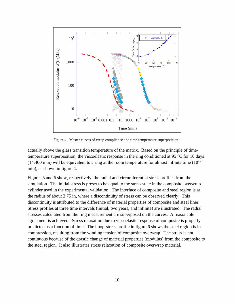
Figure 4. Master curves of creep compliance and time-temperature superposition.
actually above the glass transition temperature of the matrix. Based on the principle of time-temperature superposition, the viscoelastic response in the ring conditioned at 95 °C for 10 days (14,400 min) will be equivalent to a ring at the room temperature for almost infinite time (1010 min), as shown in figure 4.
Figures 5 and 6 show, respectively, the radial and circumferential stress profiles from the simulation. The initial stress is preset to be equal to the stress state in the composite overwrap cylinder used in the experimental validation. The interface of composite and steel region is at the radius of about 2.75 in, where a discontinuity of stress can be observed clearly. This discontinuity is attributed to the difference of material properties of composite and steel liner. Stress profiles at three time intervals (initial, two years, and infinite) are illustrated. The radial stresses calculated from the ring measurement are superposed on the curves. A reasonable agreement is achieved. Stress relaxation due to viscoelastic response of composite is properly predicted as a function of time. The hoop-stress profile in figure 6 shows the steel region is in compression, resulting from the winding tension of composite overwrap. The stress is not continuous because of the drastic change of material properties (modulus) from the composite to the steel region. It also illustrates stress relaxation of composite overwrap material.
10
100
1000
104
10-9 10-7 10-5 0.001 0.1 10 1000 105 107 109 1011 1013
Rel
axat
ion
mod
ulus
, E(t
) (M
Pa)
Time (min)
0
3
6
9
20 40 60 80 100 120
quadratic fit
Shi
ft f
acto
r, lo
g a T
Temperature ( oC)

11
Figure 5. Radial-stress profile prediction and a comparison to the ring relaxation experiment.
Figure 6. Hoop-stress profile prediction of the ring experiment.

12
4. Relaxation of Thermal Stresses
The time-dependent thermal viscoelastic behavior of a 100-layer, AS-4/3502 (graphite/PEEK)
composite cylinder subjected to a temperature increase is examined. Initial
residual stress built up in the cylinder due to the T. The composite cylinder has an inner radius in, an outer radius in, and a thickness of each layer h = 6.0 × 10⁻³ in.
Stacking sequence is given as [0/30/60/90]25 from inside out, with the 0 direction coinciding with the axis of the cylinder. The creep property of an AS-4/PEEK graphite/epoxy composite with a fiber volume fraction of 0.67 was measured at different temperatures by Kim and Hartness (14). The study shows that an increase of compliance with time due to creep behaviors of material was found at elevated temperatures. A least-squares curve fitting was used to express the transverse and shear creep from the original AS-4/3502 data in power law forms as follows:
(37)
and
. (38)
S022 and S0
66 are defined in the previous section. The compliance in the fiber direction,
, S33(t)= S22(t), and Poisson’s ratios, , are assumed
to be time-independent for this example simulation. Thermal expansion coefficients of the
composite in three principal directions are and
where the negative value indicates shrinkage with temperature
increase.
Figures 7 and 8 show radial displacement and radial stress profiles across the thickness of the cylinder at three instants—instantaneous (initial stress), 2 years, and infinite. The radial traction and displacement satisfied the continuity conditions at every interface of layers at all instants. The radial displacement, , will reach a steady state over a long period of time (infinite time)
because of the creep behavior of composites. In fact, the radial displacement of most layers approaches to a constant value except at the innermost and outermost portions of the cylinder. The free traction boundary at the surface of cylinders causes the gradients in the radial displacements. A similar phenomenon is also observed in the radial stress profile, which approaches to a constant over a long period of time. This long-term creep characteristic reflects the power law form, equations (21) and (22), of the creep compliance. The “saw” shaped radial stress distribution is the result of variation of fiber orientations through the thickness of the cylinder. The radial stress is continuous but the stress gradient is not. Accordingly, the stress profile illustrates the “saw” shape.
T = 150 C
a = 3.5 b = 4.1
220.1954
220S (t) = 1.7051 t + 1 S
660.2771
660S (t) = 11.3076 t + 1 S
psi/10 5.9 = S -811 0.36 = 0.3, = = 231312
C /100.5- = -611
22 33-6 = = 40.0 10 / , C
w(t)

13
Figure 7. Radial-displacement profiles in a cylinder subjected to thermal loads.
Figure 8. Radial-stress profiles in a cylinder subjected to thermal loads.
The hoop stress, , through the thickness of the cylinder, is illustrated at three instants in figure 9. There exist two distinct values (discontinuity) of across each interface of two
adjacent layers due to the various fiber orientations through the thickness. The hoop-stress profile also shows a trend of relaxation over a period of time. The hoop-stresses in 60 C and 90 C layers show a fairly steep gradient across the cylinder thickness initially. However, the gradient gradually disappears as time approaches infinity.
0.0E+00
1.0E-03
2.0E-03
3.0E-03
4.0E-03
5.0E-03
3.5 3.6 3.7 3.8 3.9 4 4.1 Radius (inch)
Rad
ial
Dis
pla
cem
ent
(in
ch)
Initial 2
Infinite
-3.0E+02
-2.5E+02
-2.0E+02
-1.5E+02
-1.0E+02
-5.0E+01
0.0E+00
3.5 3.6 3.7 3.8 3.9 4 4.1 Radius (inch)
Rad
ial S
tres
s (p
si)
Initial 2
Infinite
(t)
(t)

14
Figure 9. Hoop-stress profiles in a cylinder subjected to thermal loads.
5. Relaxation of Mechanical Stresses
In the following study, creep and stress relaxation of a composite cylinder subjected to internal pressure is investigated. The calculation is performed using a 0.6-in-thick composite cylinder with a lay-up construction of [0/30/60/90]25. Calculations have been performed using similar basis graphite/epoxy composite materials. The material properties are the same as described in the previous section. A pressure load of 1000 psi was applied at the inner radius of the cylinder. Some selected displacement and stress profiles from the model prediction are illustrated and discussed in the following sections.
Figure 10 shows the radial displacement through the thickness of cylinder at three instants—instantaneous (initial stress), two years, and infinite time. The radial displacement profile clearly illustrates the creep behavior of cylinder. The inner radius of the cylinder increases over a period of time because of the application of inner pressure. The outer radius actually shrinks down because of creep characteristics. The radial strain that is equal to the gradient of radial displacement increases over a period of time.
Figure 11 illustrates the relaxation of radial stresses through the thickness at three instants. The radial stress at the inner radius is 1000 psi, equivalent to the pressure applied. The radial stress is zero at the outer surface of the cylinder since it is traction-free. The curve is constructed by connecting the stress value at all the interfaces of layers. The “saw shape” of curve is due to the variation of fiber orientations through the thickness. Significant relaxation occurs over a period of time as shown in the radial stress profiles.
-2.0E+04
-1.0E+04
0.0E+00
1.0E+04
2.0E+04
3.0E+04
3.5 3.6 3.7 3.8 3.9 4 4.1 Radius (inch)
Ho
op
Str
ess
(psi
)
Initial 2 Infinite

15
Figure 10. Radial-displacement profiles in a cylinder subjected to internal pressure.
Figure 11. Radial-stress profiles in a cylinder subjected to internal pressure.
The hoop-stress profiles at three instants are illustrated in figure 12. The stress is not continuous from layer to layer due to the change of fiber orientation. The gradient of the stress profile is mainly due to curvature of cylinder. The 90 C layers have higher stresses because they are stiffer in the circumference direction and, thus, carry more loads. The viscoelastic effect is quite interesting as observed in the hoop-stress profiles changes over a period of time. The hoop stress at the inner radius increases, while it decreases at the outer radius. The integration of hoop stress through the thickness should be balanced with the inner pressure applied if a free body is taken from the cylinder. Since the stress gradient increases over a period of time, the hoop-stress will also increase at the inner radius of cylinder.
0.0E+00
2.0E-03
4.0E-03
6.0E-03
8.0E-03
3.5 3.6 3.7 3.8 3.9 4 4.1
Radius (inch)
Rad
ial
Dis
pla
cem
ent
(in
ch) Initial
2
Infinite
-1000
-800
-600
-400
-200
0
3.5 3.6 3.7 3.8 3.9 4 4.1 Radius (inch)
Rad
ial S
tres
s (p
si)
Initial
2
Infinite

16
Figure 12. Hoop-stress profiles in a cylinder subjected to internal pressure.
6. Conclusions
An analysis has been developed for viscoelastic behavior of laminated composite cylinders with ply-by-ply variation of anisotropic viscoelastic properties, which cannot be studied using an isotropic model. Stress relaxation and creep are properly determined in a cylinder subjected to a thermal and mechanical loads. Emperimental validation was conducted using a high-tensioned, overwrapped steel-ring experimental. Radial stress at the composite-steel interface was predicted and compared with the measurement. A good agreement was obtained. The anisotropic viscoelastic behavior of the composite causes interesting characteristics in cylinders, which are critical for the durability of the structure. Creep and stress relaxation could exist in the fiber direction even though the fiber dominant properties are elastic. This is mainly due to the contribution of the Poisson's ratio effects of transverse and shear properties. Viscoelastic characteristics are critical to the service life cycle of applications such as pressure vessels and composite rotors designed with built-in pre-stress to achieve desired mechanical performance.
0.0E+00
1.0E+04
2.0E+04
3.0E+04
4.0E+04
5.0E+04
3.5 3.6 3.7 3.8 3.9 4 4.1 Radius (inch)
Ho
op
Str
ess
(psi
)
Initial
2 Yrs
Infinite

17
7. References
1. Ferry, J. D. Viscoelastic Properties of Polymers; John Wiley & Sons, Inc.: New York, 1961.
2. Muki, R.; Sternberg, E. On Transient Thermal Stresses in Viscoelastic Materials With Temperature Dependent Properties. J. of Applied Mechanics 1961, 28 (2), 193–207.
3. Schapery, R. A. Application of Thermodynamics to Thermomechanical, Fracture, and Birefringent Phenomena in Viscoelastic Media. J. of Applied Physics 1964, 35 (5), 1451–1465.
4. Williams, M. L. Structural Analysis of Viscoelastic Materials. AIAA Journal 1964, 2 (5), 785–808.
5. Christensen, R. M. Theory of Viscoelasticity, An Introduction, 2nd edition; Academic Press, Inc.: New York, 1982.
6. Hashin, Z. Viscoelastic Behavior of Heterogeneous Media. J. of Applied Mechanics 1965, 32, 630–636.
7. Schapery, R. A. Stress Analysis of Viscoelastic Composite Materials. J. of Composite Materials 1967, 1, 228–267.
8. Rogers, T. G.; Lee, E. H. The Cylinder Problem in Viscoelastic Stress Analysis. Quarterly of Applied Mathematics 1964, 22, 117–131.
9. Tzeng, J. T.; Chien, L. S. A Thermal/Mechanical Model of Axially Loaded Thick-Walled Composite Cylinders. J. of Composites Engineering 1994, 4 (2), 219–232.
10. Chien, L. S.; Tzeng, J. T. A Thermal Viscoelastic Analysis for Thick-walled Composite Cylinders. J. of Composite Materials 1995, 29 (4), 525–548.
11. Souza, F. V.; Allen, D. H. Multiscale Modeling of Impact on Heterogenous Viscoelastic Solids Containing Evolving Microcracks. International Journal for Numerical Methods in Engineering 2010, 82, 464–504.

18
12. Wineman, A. Nonlinear Viscoelastic Solids – A Review. Mathematics and Mechanics of Solids 2009, 14 (3), 300–366.
13. Kim, R. Y.; Hartness, J. T. Time-dependent Response of AS-4/PEEK Composite. Proceedings of the 19th International SAMPE Conference, Crystal City, VA, 13–15 October 1987; Society for the Advancement of Material and Process Engineering: Covina, CA, 2008; 468–475.

NO. OF NO. OF COPIES ORGANIZATION COPIES ORGANIZATION
19
1 DEFENSE TECHNICAL (PDF) INFORMATION CTR DTIC OCA 8725 JOHN J KINGMAN RD STE 0944 FORT BELVOIR VA 22060-6218 1 DIRECTOR (HC) US ARMY RESEARCH LAB IMAL HRA 2800 POWDER MILL RD ADELPHI MD 20783-1197 1 DIRECTOR (PDF) US ARMY RESEARCH LAB RDRL CIO LL 2800 POWDER MILL RD ADELPHI MD 20783-1197 1 GOVT PRINTG OFC (PDF) A MALHOTRA 732 N CAPITOL ST NW WASHINGTON DC 20401 1 DIRECTOR US ARMY RESEARCH LAB AMSRD ARL WM MB A FRYDMAN 2800 POWDER MILL RD ADELPHI MD 20783-1197 1 PEO CS&CSS PM LTV SFAE CSS LT (M114 MGR) 6501 E ELEVEN MILE RD WARREN MI 48392-5000 2 NAVAL RSRCH LAB R MEGER CODE 6750 WASHINGTON DC 20375 1 COMMANDER US ARMY TACOM PM GROUND SYS INTEGRATION SFAE GCSS W GSI R LABATILLE 6501 ELEVEN MILE RD WARREN MI 48397-5000 2 BENET LABS AMSTA AR CCB E KATHE A LITTLEFIELD WATERVLIET NY 12189
2 OFC OF NAVAL RSRCH R HOFFMAN R ELLIS 800 N QUINCY ST ARLINGTON VA 22217-5660 5 NSWC C GARNETT G30 C PETRY G30 K LEWIS B MCGLASSON G32 DAHLGREN VA 22448 3 DARPA J GOLDWASSER M MAHER N WIEDENMAN 675 N RANDOLPH ST ARLINGTON VA 22203-2114 1 DIR LLNL S DETERESA PO BOX 808 LIVERMORE CA 94550 2 NASA LANGLEY RSRCH CTR T K O’BRIEN W JACKSON MS 266 HAMPTON VA 23681-0001 3 DIR DIA TA 5 K CRELLING Y MACHERET J TEICHMAN WASHINGTON DC 20310 1 US ARMY AVN & MIS CMND AMSRD AMR W C MCCORKLE 5400 FOWLER RD REDSTONE ARSENAL AL 35898-5000 4 US ARMY TACOM TARDEC AMSTA TR A LIJOI M TOURNER S KNOTT C KORSON MS 207 WARREN MI 48397-5000

NO. OF NO. OF COPIES ORGANIZATION COPIES ORGANIZATION
20
2 US ARMY TACOM ARDEC AMSRD AAR AEP M CILLI J LUTZ BLDG 382 PICATINNY ARSENAL NJ 07806-5000 1 IAP RESEARCH INC D BAUER 2763 CULVER AVE DAYTON OH 45429-3723 1 TITAN CORP T WOLFE 4855 RUFFNER ST STE A SAN DIEGO CA 92123 4 UNIV OF TEXAS AT AUSTIN CTR FOR ELECTROMECHANICS J HAHNE M WERST J HERBST K T HSIEH PRC MAIL CODE R7000 AUSTIN TX 78712 2 DEPUTY ASST SECY FOR R&T SARD TT J SINGLETON M DONOHUE SAAL TR STE 9800 2511 JEFFERSON DAVIS HWY ARLINGTON VA 22202-3911 1 DIRECTOR US ARMY RESEARCH LAB RDRL SED E SHAFFER BLDG 204 RM 4C120 2800 POWDER MILL RD ADELPHI MD 20783-1197
ABERDEEN PROVING GROUND
62 DIR USARL RDRL SL R COATES RDRL VTM A GHOSHAL D LE C SHIAO
RDRL WM P BAKER B FORCH J MCCAULEY RDRL WML M ZOLTOSKI RDRL WML D D BEYER J SCHMIDT RDRL WML F G KATULKA D LYON RDRL WML G D DRYSDALE J SOUTH RDRL WML H J NEWILL B SORENSEN RDRL WMM J BEATTY R DOWDING P SMITH J ZABINSKI RDRL WMS M VANLANDINGHAM RDRL WMM A R EMERSON L HOLMES J GARDNER M GRIEP D O’BRIEN T PLAISTED J SANDS E WETZEL J TZENG (5 CPS) RDRL WMM B T BOGETTI R CARTER R DOOLEY B CHEESEMAN D HOPKINS R KARKKAINEN B POWERS C YEN RDRL WMM C R JENSEN RDRL WMM D R BRENNAN V CHAMPAGNE E CHIN K CHO S WALSH RDRL WMM E J SINGH

NO. OF COPIES ORGANIZATION
21
RDRL WMM F H MAUPIN L KECSKES RDRL WMP S SCHOENFELD RDRL WMP A J POWELL RDRL WMP B C HOPPEL S SATAPATHY RDRL WMP D R DONEY M KEELE J RUNYEON RDRL WMP E M BURKINS P SWOBODA RDRL WMP F A FRYDMAN N GNIAZDOWSKI

22
INTENTIONALLY LEFT BLANK.