vision and technique behind the new studios and … · new studios and listening rooms of the...
TRANSCRIPT

Vision and Technique behind the New Studios and Listening Rooms of the
Fraunhofer IIS Audio Laboratory Andreas Silzle1, Stefan Geyersberger1, Gerd Brohasga1, Dieter Weninger1,2 and Michael Leistner3
1 Fraunhofer Institute for Integrated Circuits IIS, Am Wolfsmantel 33, D-91058 Erlangen, Germany
2 Innovationszentrum für Telekommunikationstechnik GmbH IZT, Am Weichselgarten 5, D-91058 Erlangen, Germany
3 Fraunhofer Institute for Building Physics IBP, Nobelstraße 12, D-70569 Stuttgart, Germany
Correspondence should be addressed to Andreas Silzle ([email protected])
ABSTRACT
The new audio laboratory rooms of the Fraunhofer IIS and their technical design are presented here. The vision behind them is driven by the very high demands of a leading edge audio research organization with more than 100 scientists and engineers. The 300 m2 sound studio complex was designed with the intention of providing capabilities that are in combination far more extensive than those available in common audio research or production facilities. The reproduction room for listening tests follows the strict recommendations of ITU-R BS 1116. The results of the qualification measurements regarding direct sound, reflected sound, and steady state sound field will be shown and the construction efforts needed to achieve these values are explained. The connection from all the computers in the server room to more than 70 loudspeakers in the reproduction rooms, other audio interfaces, and the projection screens is done by an audio and video routing system. The architecture of the advanced control software of this routing system is presented. It allows easy and flexible access for each class of user to all the possibilities made available by this completely new system.
1. INTRODUCTION
The new audio laboratory rooms of the Fraunhofer IIS and their technical design are presented here. The vision
behind them is driven by the very high demands of a leading edge audio research organization with more than 100 employees in the audio and multimedia business field. This was a once in a lifetime chance to design a 300 m2 sound studio complex with the intention
Silzle et al. Audio Laboratory Rooms
Page 2 of 15
of providing capabilities that are in combination far more extensive than those available in common audio research or production facilities. All the technical parameters have to fulfill perceptually motivated requirements. The utility and usability have to be adapted to the wide range of requirements of demanding audio scientists and engineers.
2. VISION AND REQUIREMENTS
Fraunhofer IIS in Erlangen, Germany is one of the most active and innovative audio research organizations contributing to many of the commercially successful open standards-based audio compression schemes such as MPEG Layer-3 and MPEG AAC. All those efforts and contributions are based on scientific findings which always have to be implemented and tested in a standardized environment – in the case of audio this has to be a listening room built according to the well known ITU-R BS 1116-1 recommendation [1]. In its former building the audio and multimedia departments of Fraunhofer IIS had such a room [2], where thousands of listening tests of all types were conducted over the last 15 years. This room was in use 24/7 and had to fulfill many additional purposes such as demonstrating Fraunhofer technologies to interested customers while at the same time conducting an important MPEG listening test. In the late 90s roughly 20-30 scientists were actively working on audio compression related topics at the Fraunhofer IIS, and over the last 10 years these activities have been heavily expanded to address new topics like surround sound, binaural processing, semantic audio processing, audio communication technologies, multimedia streaming, and combined voice and music compression schemes. The size of the team has also increased to now more than 100 engineers and scientists, resulting in a move to a new building and creating a high demand for new audio rooms.
To define the kind of rooms necessary for these efforts, it is helpful to have the auditory signal processing chain in mind:
Auditory Signal Processing Chain
a) Recording of the acoustic eventb) Signal transmission and processingc) Audio reproductiond) Auditory perceptione) Quality judgment
For successfully developing audio algorithms, it is very useful to have access to and control over all parts of this auditory signal processing chain. For every step in this chain, special rooms considerably increase the quality of the work.
a) To improve existing audio coding standards or todevelop new audio algorithms, it is extremely useful to have full control over the audio source material (the first part of the signal processing chain). With the help of our own recording studio every usual or even unusual music instrument combination and every microphone set-up is under full control and can be manipulated in any way desired. Additionally, different mix-downs can be generated from the same source material, which are normally not available. Another huge advantage is to be able to produce our own sound demonstration and test material.
b) The development and implementation of the audioalgorithms is carried out by the scientists and the engineers in their offices.
c)-e) Many technologies that are developed in the audio and multimedia business field are based on psychoacoustic principles. Consequently, a large number of listening tests are conducted. Therefore, a huge effort was dedicated to the planning and implementation of the main reproduction and listening test room. The ITU-R BS 1116-1 recommendation is the strictest specification regarding the properties of a listening test room. It describes the proportions of the room controlling room modes, the noise floor, the reverberation time over frequency, the operational room response of the loudspeakers to the listener position, and the early reflections.
The requirements for the rooms are derived from their function and from human auditory perception. The hearing area is shown in Figure 1. The threshold of hearing determines the allowed background noise. It is defined in NR and GK curves. The GK curves, standardized in Germany [3], and the difference to noise rating (NR) curves are described in [4]. The func-tionality of the room defines the size and volume of it.

Silzle et al. Audio Laboratory Rooms
The volume of the room in turn defines the reverberation time Tm. In general, the reverberation time of such audio rooms should be low and relatively frequency independent, but should not be zero, such as in an anechoic measurement room. Human hearing is adapted to a reflective environment. Therefore listening tests have to be done in a reflective environment. The functional requirements for the different audio rooms are listed subsequently.
Audio Room Functional Requirements
a) Large recording roomb) Speaker and single instrument recording roomc) Control and mixing roomsd) High quality reproduction room with space for
3D loudspeaker set-upsFigure 1: Hearing area, i.e. area between hearing
threshold in quiet and threshold of pain. Also indicated are the areas encompassed by music and speech, and the limit of damage risk. The ordinate scale is expressed in sound pressure level. The dotted part of the threshold in quiet stems from subjects who frequently listen to very
loud music. The figure was taken from Zwicker and Fastl [5].
e) Cinemaf) Typical living roomg) Headphone reproduction roomh) Technical and server rooms
The different audio rooms, some of their main properties and requirements are summarized in Table 1.
Room and Functionality Size [m2]
Volume [m3]
Requirement towards
background noise
Tm [s]
See Room Name
Main reproduction and listening test room
70 300 NR 10 0.36 Figure 3 Mozart
Audio/video recording room 90 500 GK 20 0.45 - Zimmer Cinema with 70 seats - - GK 25 0.41 Figure 16 - Control room 1 49 - GK 20 0.29 - Morricone Control room 2 25 - GK 20 0.23 Figure 17 Strawinsky Typical living room 35 - - - - BachHeadphone reproduction room 13 - - - - Beethoven Speaker and single instrument recording room
20 - - - - Hendrix
Two server and technical rooms - - - - - Glass and Stockhausen
Table 1: Audio rooms and some of their main properties
3. ROOMS
Among this room ensemble the biggest effort was spent on design and realization of the main reproduction and listening test room Mozart. The
following paragraphs will provide some insight into the requirements, realization details, and achieved results for this room from the construction point of view.
Page 3 of 15
Silzle et al. Audio Laboratory Rooms
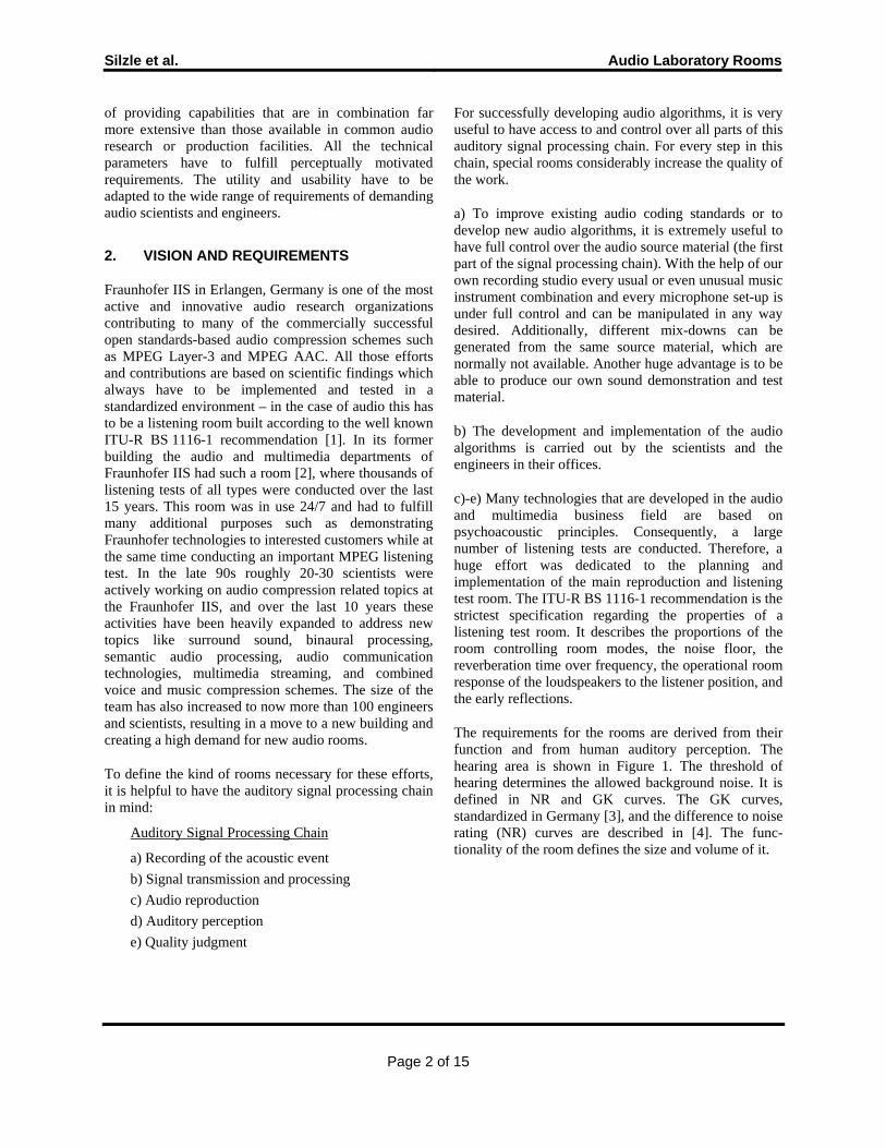
Figure 2: Floor plan of the main reproduction room Mozart and the adjacent rooms.
nx ny nz f [Hz] 1 0 0 17.7 0 1 0 21.7 1 1 0 28.0 2 0 0 35.4 0 0 1 39.0 2 1 0 41.5 1 0 1 42.8 0 2 0 43.4 0 1 1 44.6 1 2 0 46.9 1 1 1 48.0 2 0 1 52.6 3 0 0 53.0 2 2 0 56.0
Table 2: Distribution of the first room modes in the main reproduction room
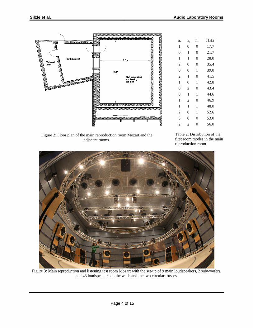
Figure 3: Main reproduction and listening test room Mozart with the set-up of 9 main loudspeakers, 2 subwoofers, and 43 loudspeakers on the walls and the two circular trusses.
Page 4 of 15
Silzle et al. Audio Laboratory Rooms
3.1. THE MAIN REPRODUCTION ROOM
3.1.1. Dimensions As mentioned before, it was agreed that the room was to be constructed according to ITU-R BS.1116-1, because this room will be mainly used for listening tests. Another requirement was to create a flexible room for future research activities which are not foreseeable at the moment. To have the possibility to realize a number of different multichannel setups described in ITU-R BS 775-1 [6], and especially three dimensional setups with speakers hanging from the ceiling, it is advantageous to construct a large room. In a first step, the dimensions were considered. ITU-R BS.1116-1 recommends either a rectangular or a trapezoidal room form. A rectangle was chosen, because it is closer to the standard living room – the environment, in which the acoustic material produced and evaluated in this room will be played in the majority of cases. Length (l), width (w), and height (h) of the room should be such that the net floor area is between 30 and 70 m2 for the intended multi-channel reproduction, and should fulfill the relationships
45.41.1 −≤≤hw
hl
hw (1)
and
3,3 <<hw
hl (2)
By choosing ln = 9.3 m, wn = 7.5 m, and hn = 4.2 m, where the index n denotes net values including acoustic lining, in contrast to l = 9.7 m, w = 7.9 m, and h = 4.4 m, which represent the rooms raw inside dimensions, the net floor area turns out to be 69.75 m2. The selection of such large values of l, w, and h just meeting the area range specified and the constraints of (1) and (2) was made for two reasons. First, to prevent the case where some low frequency bands do not have room modes present, since with larger dimensions the room mode density will be as high as possible, and second, the room modes will have a reasonably uniform frequency distribution. Both effects are desirable in order to achieve a well-balanced sound. Figure 2 shows the floor plan of the main reproduction room and the adjacent control and server and technical room. See Table 2 for the distribution of the first room modes. The set-up of 9 main loudspeakers, 2 subwoofers, and 43
loudspeakers on the walls and the two circular trusses in the main reproduction room Mozart can be seen in Figure 3.
3.1.2. Sound Insulation
The listening conditions will be influenced by the background noise within the room. Background noise has its origin in any kind of building services (e.g. ventilation, heating, air conditioning, etc.) or studio equipment (e.g. amplifier, computer, etc.). The source of the background noise can be inside or outside the room. Airborne and structure-borne sound insulation measures must insure that the background noise level in the room does not exceed the limits imposed by ITU-R BS.1116-1, which is preferably the NR 10 curve, while the minimum requirement is the NR 15 curve. A special challenge in satisfying this requirement was the fact that a heat and power plant, an absorption chilling machine, and 5 heating, ventilation and air conditioning (HVAC) units had to inevitably be installed in the basement of the same part of the building. For this reason it was decided to erect the main reproduction room as a room-in-room structure, see Figure 2. It rests on damped spring pads, which form together with the room a spring mass system with a resonance frequency of 10 Hz. The inner room has a mass of about 200 metric tons, indicating the massive design of the construction. Besides the room-in-room structure, a gap between building parts, which has a very big impact on the statics of the building, was integrated directly around the main reproduction room to further uncouple it from background noise sources.
Due to the fact that the main reproduction room will be used by up to ten persons simultaneously, it is essential to install an efficient and very quiet HVAC system. An important precondition to achieving a quiet system is a low air velocity within the HVAC system. Since low air velocity depends directly on the cross section many ventilation openings were employed. (See the black holes in the ceiling in Figure 3.) The system has sixteen supply air injectors and six exhaust air shafts. Flexible couplings are used to decouple the in- and outputs from the HVAC units. The HVAC unit of the main reproduction room can be adjusted for an airflow of 20 percent or 1000 m3/h (1.4 m/s) up to a maximum of 100 percent or 4300 m3/h (6.0 m/s). The room temperature can be regulated with a thermostat from 17 to 25 degrees Celsius. Figure 4 shows the construction of the HVAC system on the ceiling of the inner room.
Page 5 of 15

Silzle et al. Audio Laboratory Rooms
Figure 4: Plan of the HVAC system of the main reproduction room Mozart
The red graph (with circles) in Figure 5 shows the measured noise level when the HVAC system supplying the main reproduction room is turned off, but all other machinery in the basement is running. A valid acoustic signal can only be picked up below 500 Hz with the high quality measurement equipment used, see appendix. Above 500 Hz there is just the noise of the microphone preamplifier. From this result it can be concluded, that neither airborne nor structure-borne disturbances from any of the installed machinery are present in the room. The blue (triangle) and green (diamond) graphs show measurements with the air supply of the main reproduction room turned on. At 80% of the maximum supply rate NR 10 is still fulfilled, whereas at 100% air rate it is not. These excellent values show that the design and implementation of the room-in-room construction and the HVAC system exceed the requirements.
Figure 5: NR10 and background noise levels in different operating states in the main reproduction
room Mozart. Additionally, the threshold of hearing of narrow band noise in a diffuse sound field according to DIN EN ISO 389-7 [7] is given.
Since ITU-R BS.1116-1 does not specify a requirement for the sound level difference between adjacent rooms, it has, according to DIN 15996 [3], been defined as the difference between the operational sound level in the loudest adjacent room and the allowed background noise. It was agreed to assume as the level in the loudest adjacent room the operational sound level in studios which do not serve for music production, given in DIN 15996. The sound level difference was measured exemplary between the main reproduction room and its adjacent control room. It appeared appropriate to do so, because between these two rooms is the only wall that contains openings (a door and a window), and can hence be expected to have the lowest sound insulation of all surfaces. Figure 6 shows that the achieved sound level difference is sufficiently high.
Page 6 of 15

Silzle et al. Audio Laboratory Rooms
Figure 6: Required and achieved sound level difference from the adjacent control room into the
main reproduction room Mozart.
Neither ITU-R BS.1116-1, nor other applicable standards for studio design express precise requirements for impact sound insulation. Nevertheless, impact sound generated by a standardized impact sound generator has been measured for the following two generator positions: in the control room of the main reproduction room, and in the corridor of the 3rd floor adjacent to the outer wall of the room-in-room construction. The measured sound levels are shown in Figure 7 and can be considered to be extraordinary low.
3.1.3. Room acoustics
The room acoustic requirements in ITU-R BS.1116-1 are quite comprehensive and rigorous. They are directed towards reverberation time, operational room response, early reflections, and late energy. The required values for the respective quantities will be mentioned in the paragraph where they are discussed.
Figure 7: Noise measured in the main reproduction room Mozart generated by a standard impact
generator positioned at two different sites outside that room.
In an attempt to meet all demands while still trying to use a construction not too different from a standard living room, it was agreed to install acoustic treatments (i.e. absorbers) on the walls and ceiling, while the floor was covered with carpet. Should the first sound reflection from speakers to listener via the floor cause too strong a comb filter effect, then additional measures may be applied to solve the problem. A patchwork of porous and resonance type absorbers was mounted to the walls and ceiling, symmetrically to the longitudinal and transversal axes of the room with respect to the reference listening position. They were then covered with highly perforated metal grid over a fiberglass fleece layer having an extremely low acoustic flow resistance. All the following measurement results were made in the fully equipped room including 54 loudspeakers, either mounted to the two circular trusses, the wall, or free standing, and equipment racks, a flat screen TV,
Page 7 of 15

Silzle et al. Audio Laboratory Rooms
a projection screen, and tables and chairs, see Figure 3.
ITU-R BS.1116-1 requires a room volume dependent reverberation time Tm with an average value, measured over the frequency range from 200 Hz to 4 kHz1, of
( ) 31025.0 VVTm = (3)
where V is the volume of the room, and V0 is a reference volume of 100 m3. In this frequency region there is only a tolerance of ±0.05 s allowed. Applying the actual volume of the main reproduction room (293 m3) to this formula gives a desired Tm of 0.36 s. The measured reverberation time, shown in Figure 8, has a Tm of 0.33 s, a deviation of 8% which is acceptable, and fits nicely into tolerance band specified by the standard, as shown in Figure 8.
Figure 8: Measured reverberation time of the main reproduction room Mozart. The gray shaded area is
the allowed range of tolerance.
According to ITU-R BS.1116-1, the operational room response curves are defined as the one-third octave frequency responses of the sound pressure levels produced by each monitor loudspeaker at the reference listening position, using pink noise over the frequency range from 50 Hz to 16 kHz. The measurement result for the main monitor loud-speakers belonging to the 5.1 set-up is presented in Figure 9. The values outside the range of tolerance
Page 8 of 15
1 Note that the formula value changed from 0.3 to 0.25 in the recommendation version dated 1994 to the version dated 1997.
allowed by the standard around 200 Hz correspond to a destructive interference, caused by the first reflection of sound from speakers to listening position via the floor. This was expected, and it is currently being evaluated whether or not the problem is considered to be severe enough that additional measures must be taken to solve it. Besides, the loudspeakers have not been investigated separately, so individual deviations in their frequency response may contribute a small degree to the overall result.
Figure 9: Operational room response of the main monitor loudspeakers used for 5.1 listening in the main reproduction room Mozart. The gray shaded
area is the allowed range of tolerance.
There is an additional requirement regarding the front loudspeakers. The differences between the operational room responses produced by each of them at the reference listening position should not exceed 2 dB within the whole frequency range. Figure 10 shows the measurement result. Since floor reflections cancel out in the subtraction of sound levels, other reasons such as room asymmetries, reflections from equipment in the room, or again individual loudspeaker differences are responsible for the deviations. Investigation is still in progress. Nevertheless, the results now achieved are remarkably good.
Regarding early reflections caused by the boundary surfaces of the listening room, which reach the listening area during a time interval up to 15 ms after the direct sound, ITU-R BS.1116-1 specifies that they

Silzle et al. Audio Laboratory Rooms
should be attenuated in the frequency range from 1 kHz to 8 kHz by at least 10 dB relative to the direct sound. Figure 11 shows sections of the first 30 ms of two impulse response measurements, band pass filtered from 1 kHz to 8 kHz, both from the center loudspeaker to the reference listening position. The graphs are almost identical with each other, except around 13 ms. The first 10 ms with zero signals represent the direct sound travel time, the strong peaks at 10 ms originate from the direct sound. In the measurement of the untreated room with the regular carpet covered floor (black graph), a second peak at 13 ms with 0.6 amplitude relative to the direct sound, which is equivalent to 4.5 dB attenuation, represents the reflection caused by the floor. The time delay of 3 ms corresponds exactly to the 1.7 m path length difference between direct and reflected sound. This strong reflection violates the requirements of the standard. It can however be attenuated to a negligible level with little effort by placing a piece of moderately absorbing material (e.g. 50 mm thick porous material, about 1.5 m x 1 m) on the floor at the mirror point, i.e. the point, where the sound is reflected on the floor. The measurement result for this case is presented with the red graph in Figure 11. None of the reflections exceeds 0.3 amplitude relative to the direct sound, which is equivalent to more than 10 dB attenuation. The other loudspeakers exhibit similar behavior and can be treated in the same way.
Figure 10: Differences in the operational room responses of the 3 front monitor loudspeakers
belonging to the 5.1 set-up in the main reproduction room Mozart. The gray shaded area is the allowed
range of tolerance.
Figure 11: Main reproduction room, measured impulse responses, band pass filtered from 1 kHz to 8 kHz, from the center loudspeaker to the reference
listening position.
3.1.4. Subjective room assessment
The room has been subjectively assessed by several audio experts by listening to various stereo and multichannel sound material and by listening to hand clapping and natural voice sounds. No anomalies in the sound field like flutter echoes or tonal colorations have been found. All listeners so far expressed their satisfaction about the achieved acoustic properties, especially neutrality, which is indispensable for the intended use. Although not visible in the rever-beration time measurements, an unexpected positive audible influence is caused by the two large trusses with the large number of mounted loudspeakers. The room sounds by these early reflections more lively and natural, compared to the "empty" room before and to other ITU-R BS.1116 rooms, which often evoke a slight "under water" sound feeling, especially when the ceiling is low and highly damped. There were also some discrete resonance frequencies audible at the beginning. The most audible were caused by the metallic trusses. After filling them with sand, the problem was removed2.
Several experienced listeners were astonished about the very precise phantom center reproduction. Only after switching off the center loudspeaker they believed that the center was not used. Furthermore, the size of the room (with the low eigenfrequencies) is a very big advantage for the low frequency
2 Luckily the suspensions were able to carry these extra 400 kg of load.
Page 9 of 15

Silzle et al. Audio Laboratory Rooms
reproduction. The sound is just dry and deep. The big loudspeaker radius of 3 m results in some new perceptual experiences. The perceived opening angle of a stage or instrument keeps the same as with a smaller radius, but the absolute size of an instrument gets larger than expected. We will experiment in the future with smaller loudspeaker radiuses to investigate this. Regarding the floor reflection, the audible influence by removing this with absorbers around the listener is negative – unnatural sounding. No normal room has an absorbent floor. The human brain seems to be used to this. Future investigation will cover the usefulness of this part of the ITU recommendation. The typical listening situation is presented in Figure 12.
Figure 12: Listener in Mozart
3.2. OTHER ROOMS
Besides the main reproduction room there are other rooms with elevated acoustic requirements, see Table 1. However, the requirements are less in number –just background noise and the derived necessary sound level difference, plus reverberation time – and they are significantly less rigorous. Measurement results can be summed up as follows.
Measurement Results for other Rooms
a) Background noise requirements can befulfilled if the air supply rate is adjusted to avalue determined for each roomindividually.
b) Necessary sound level differences have beenobtained under the respectively assumedoperational sound levels of the adjacentrooms.
c) Reverberation times fall with reasonableaccuracy into the respective toleranceranges, taking the achievable precision ofmeasurement into account. This appliesespecially to the cinema, since thererequirements down to the 31 Hz octave bandhave been expressed.
4. EQUIPMENT
The selection and set-up of the equipment are guided by the requirements of the users. There are very different users and therefore different requirements in such a large research and development department. There are often users who want to do certain tasks quickly, but they are inexperienced with the equipment and the connections between them. We call them standard users. On the other side there are power users, who like to build difficult set-ups of combinations of equipment, and they like to save, recall and maybe automate the settings of the equipment. Both user groups need different user interfaces and different insight in the connections of the hardware. Both user groups need presets, with which they can reliably recall set-ups. For the standard user it should be possible to use the equipment without the necessity to understand all the details of the complete set-up. The power user should have full access to all options of the equipment. For none of the two groups it should be necessary to have an engineer or technician at the side who translates the user’s wishes into re-cabling and button pushes on the equipment. For more details on the remote control software see paragraph 5. To fulfill all these user requirements the equipment follows the following guidelines.
Equipment Requirements
a) Professional equipment for professionalusers
b) High flexibility to fulfill as many demandsas possible from the different users
c) Three different user levels: standard-,power- and admin user
d) Easy user interfaces especially for thestandard user
e) Full integration of computers into the audioand video chain
f) Every audio room can be usedindependently from each other
Page 10 of 15

Silzle et al. Audio Laboratory Rooms
g) Every audio room can be connected to anyother audio room
h) Only the admin user has control over crossconnections of the equipment between theaudio rooms
i) A lot of presets to easily handle the differentrequirements
j) The power users can save personal presetsfor their work
The following sections list the different categories of equipment.
Figure 13: Self-noise of the different speaker set-ups in the main reproduction room Mozart
4.1. 3D LOUDSPEAKER REPRODUCTION SYSTEM
To build any three dimensional loudspeaker set-up in the main reproduction room, a two layered circular truss is suspended from the ceiling. It is equipped with a variable 3D loudspeaker set-up using high
quality studio monitors. So every future sound format can be played back in the best possible way. A free hanging loudspeaker system (useful for academic research) and a wall mounted set-up (such as used in realistic room set-ups) were implemented, to experiment with the difference between them, see Figure 3.
The self-noise of all these loudspeakers was measured, see Figure 13. All loudspeaker set-ups are well below the NR 10 curve and around the hearing threshold. Only the loudspeakers mounted on the truss have some frequency bands above the NR 10 curve.
4.2. AUDIO ROUTING SYSTEM
To fulfill the different needs of a research lab, a minimum of three different computers, with the operating systems Windows, Linux and MacOS, serve every audio room. The users are not forced to use only one specific operating system. To avoid any additional noise the computers for all audio rooms are set up in a separate server room. Every audio signal stored or played back is coming from a computer. Computer hardware and software is today much cheaper, much more flexible and exchangeable, and also more reliable (compared to some years ago) for any kind of audio recording, mixing, and play-back than any other equipment. The connection from every computer to every loudspeaker or any other audio interface (Mic, Line, AES, ADAT) is done by an audio routing system. Every computer is connected with a MADI interface, providing 64 channels (at 48 kHz), to the audio routing system and the routing system provides via MADI the necessary audio inputs and outputs in every room, which together results in more than 1500 I/O channels in the audio routing system. To avoid any trouble with different digital signals (clocks), every digital input and output (beside MADI) is equipped with a sample rate converter. A schema of the audio routing system is presented in Figure 14.
The analogue I/Os (Line) of the audio routing system have a signal to noise ratio (SNR) ≥ 110 dB(A), the transformer coupled Mic-Inputs have a SNR ≥ 127 dB(A). These excellent values fit perfectly to the very low noise floor values of the rooms. The main routing system uses 48 kHz sampling frequency, but there is extra equipment to record and play-back with higher sampling rates.
Page 11 of 15

Silzle et al. Audio Laboratory Rooms
Figure 14: Audio routing system schema
The audio routing system is configured with enough processing power to serve nearly every wish on the recording side (metering, dynamics and limiter) and on the reproduction side (metering, any kind of large down-mix matrices with factor multiplication, 8 band equalization, and sample-precise delaying on every loudspeaker output). The system is equipped with 144 DSPs (about 57 GFlops), which is similar to a large mixing console with more than 100 channels. It is important to mention that the routing system makes the audio processing for the reproduction (control room settings) independent from the audio software in the computer. Only with this design it is possible to switch between different software players or even between different computers with the guarantee that the level, EQ, delay and down-mix parameters for the loudspeaker set-up are kept the same in one reproduction room.
To avoid any electromagnetic interference all audio- and video lines have been arranged separately from the power cables. All installed cables including the power cables are shielded. Additionally, all audio equipment has its own power cables separated from the video and computer power cables. All power cables are connected in a star-shaped grounding arrangement with the center in the main electric distribution panel in the cellar.
4.3. VIDEO PROJECTION AND ROUTING
The main reproduction room should have a projector for video projection on a screen. A projector is a noise source and is therefore not allowed in this room. It is placed in an extra chamber between the walls with connection to the ventilation and a sound insulated window to the audio room. The distance from the projector to the screen is around 6 m, so a telephoto lens is necessary. An additional feature of the projector is the possibility of a lens shift. This is necessary to reproduce the picture at different heights on the screen, to appear at the ideal height for a seated audience or a standing one. The projector can be remote controlled over the RS 232 interface by the media control system.
The screen covers not only the center loudspeaker but also the left and right one, in case the screen has any acoustical influence on the audio reproduction. Therefore, a screen width of 3.5 m was necessary. This, plus the room height of 4.2 m required a custom-made motorized screen. With a screen to seat distance of around 2.3 m, a optimal picture width of 1.53m can be calculated with [8]. A woven screen was selected, because it promises less influence on the audio signal than a micro perforated one.
All audio rooms have at least two computer screens to reproduce the video signals from the dual-head graphic cards of the computers and from the DVD players. Because of the free assignment of audio inputs and outputs from every computer in the server room to every audio reproduction room, the video together with the keyboard and mouse signals has to follow, and a video routing system is necessary.
Video Routing System Requirements
a) Digital video signal routing (DVI)b) Dual head signal distribution with a screen
resolution of 1920x1200 pixelc) Routing of HDMI signals with HDCP
coding from either the computers or theDVD-players
d) Parallel USB 2.0 routing for fast file transferof audio files from USB media
e) 32 inputs and 16 outputsf) Fully externallly remote controllable
A lot of audio material is carried today on USB-sticks instead of disc media, so in addition to the DVD
Page 12 of 15
Silzle et al. Audio Laboratory Rooms
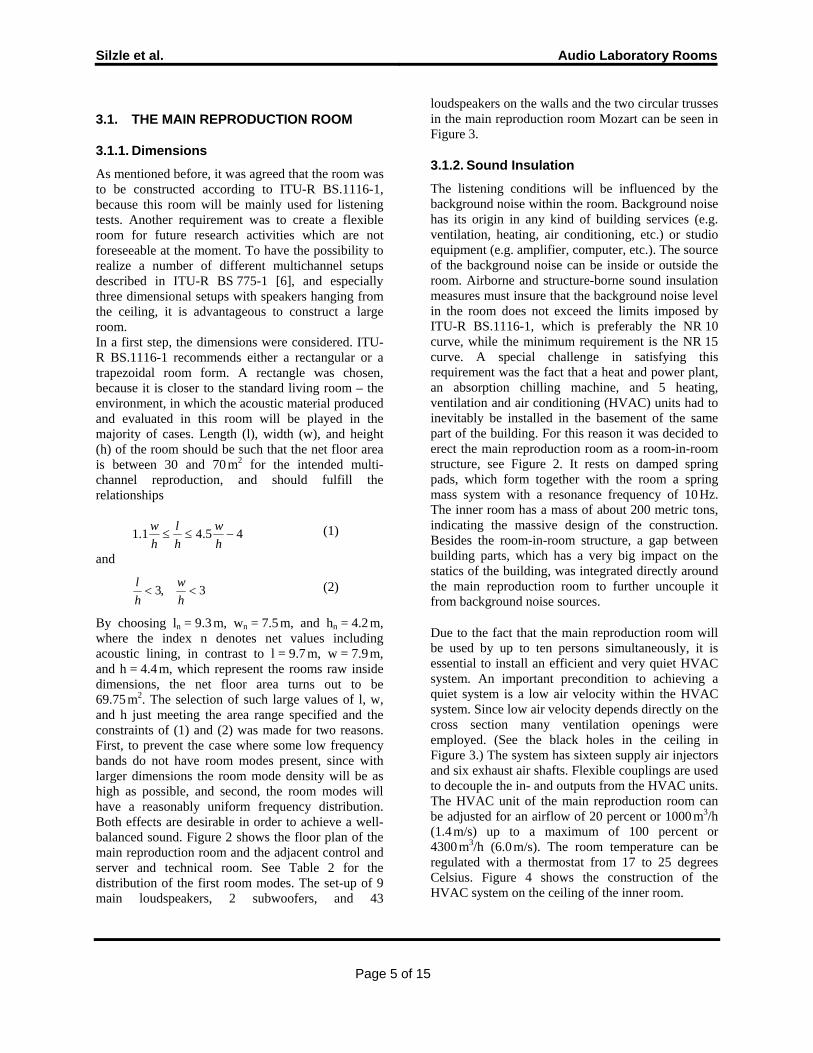
players, a USB 2.0 connection from the audio room over a special routing system to the computers is necessary. For the playback of copy protected Blu-ray disks a routing system which can handle HDMI signals is necessary and is installed. Especially the HDMI signal paths require careful planning of cable length and expansion boxes, where necessary. A simplified scheme of the video routing system is presented in Figure 15.
Figure 15: DVI and USB 2.0 routing system schema
Figure 16: Cinema with wavefield loudspeaker reproduction system
4.4. WAVE FIELD SYNTHESIS SYSTEM
To present the result of the wave field synthesis (WFS) research of our sister institute IDMT (Institute for Digital Media Technology) in Ilmenau, we also installed an IOSONO WFS reproduction in our cinema. It consists of 200 channels with 600 loudspeakers. The system can not only reproduce
special WFS material but also all types of standard multichannel signals such as from CD, DVD, DVD-A, SACD, Blu-ray, portable players or computer-based audio. Because a standard cinema loudspeaker system is also installed, a direct comparison of the two systems is possible. Additionally, it is possible to set-up and connect the universal mixing controller (see below) and the IOSONO Spatial-Audio-Workstation in the middle of the cinema, to produce and mix sound in the different formats. Figure 16 show a view into the cinema.
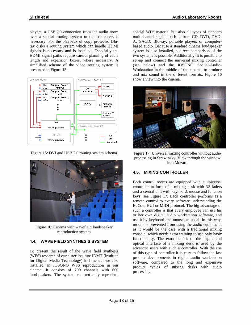
Figure 17: Universal mixing controller without audio processing in Strawinsky. View through the window
into Mozart.
4.5. MIXING CONTROLLER
Both control rooms are equipped with a universal controller in form of a mixing desk with 32 faders and a central unit with keyboard, mouse and function keys, see Figure 17. Each controller performs as a remote control to every software understanding the EuCon, HUI or MIDI protocol. The big advantage of such a controller is that every employee can use his or her own digital audio workstation software, and use it by keyboard and mouse, as usual. In this way, no one is prevented from using the audio equipment, as it would be the case with a traditional mixing console, which needs extra training to use only basic functionality. The extra benefit of the haptic and optical interface of a mixing desk is used by the advanced users with such a controller. With the use of this type of controller it is easy to follow the fast product developments in digital audio workstation software, compared to the long and expensive product cycles of mixing desks with audio processing.
Page 13 of 15

Silzle et al. Audio Laboratory Rooms
5. INTEGRATION, REMOTE CONTROL ANDUSER INTERFACE
As mentioned earlier, we would like to provide the easiest and most flexible way to control the complete set of equipment in the audio rooms by standard and power users. Therefore we designed a completely new concept of audio studio control.
Figure 18: Universal remote control unit
All technical equipment besides the computers is under the control of one media control software tool, including the audio / KVM / USB2.0 / HDMI routing system, the complete processing power of the audio routing system, the DVD-players, the projector, the motorized screen, light, air condition, etc. This allows easy and flexible access for all possible use cases. The main I/O interface is a 17” touch screen display. Attached at the side is a motorized fader, which controls the master volume control from the audio routing system - always completely independent from the (perhaps false) status of the playback computer. The fader position always gives the optical and haptic feedback of the position of the master volume. The rotary knobs above the fader ease the input of parameter values. The red mute-button above improves hearing safety in a room with more than 50 loudspeakers. This hardware I/O interface is custom designed to our specifications, see Figure 18, and four audio reproduction rooms are equipped with it.
Figure 19 presents the screen for the standard user in the main listening test room. There is a similar screen with reduced possibilities for listening test users. And there are a number of screens with much more detailed facilities for the power users. The power users have the possibility to save and recall detailed presets for the different parts of the audio routing system (connections, down-mix parameters, bass
management parameters, loudspeaker parameters, recording parameters). Each screen is customized for the configuration of a particular room. For the hierarchy of these screens see Figure 20.
Figure 19: Standard user screen for the universal remote control
Figure 20: Hierarchy of screens for different users of the universal remote control.
Page 14 of 15

Silzle et al. Audio Laboratory Rooms
Page 15 of 15
6. SUMMARY
Over the last 10 years the number of scientists that are heavily using standardized listening rooms at the Fraunhofer IIS increased to more than 100. Compared to the early days of audio compression, many new research efforts have been added, e.g. surround sound, binaural processing, semantic audio processing, audio communication technologies, multimedia streaming, and combined voice and music compression schemes. Therefore, while moving to a new building it was a big challenge to specify, plan, build and finally approve a 300 m2 studio complex which serves for the complete audio signal processing chain from recording to transmission and processing, reproduction, auditory perception and quality judgment. This studio complex with many specially selected and custom designed components fulfills all requirements given by the demanding scientists and engineers of Fraunhofer IIS. It was recently approved and is now fully operational and in use 24/7. This new studio complex is well prepared to serve as an environment for many future scientific activities in or around the complete audio signal processing chain, for example 3D sound reproduction.
ACKNOWLEDGEMENTS
The authors would like to thank colleagues inside the institute who supported the large amount of work needed to design and construct the new audio rooms. We appreciate especially the valuable comments from Ulrik Heise and Robert Bleidt. We would also like to thank all the companies involved in supporting us in our ambitious goals.
REFERENCES
[1] ITU-R, Recommendation-BS.1116-1, Methods for the subjective assessment of small impairments in audio systems including multichannel sound systems. 1997, Intern. Telecom Union: Geneva, Switzerland. p. 26.
[2] Zha, X., H.V. Fuchs, and J. Hunecke, Raum- und bauakustische Gestaltung eine Mehrkanal-Abhörraumes. RundfunktechnischeMitteilungen, 1996. 40(3): p. 77-83.
[3] DIN, 15996, Bild- und Tonbearbeitung in Film-, Video- und Rundfunkbetrieben - Grundsätze und Festlegungen für den Arbeitsplatz. 2008, Beuth Verlag: Berlin.
[4] IRT, Höchstzulässige Schalldruckpegel von Dauergeräuschen in Studios und Bearbeitungsräumen bei Hörfunk und Fernsehen, Akustische Informationen, Sachgebiet Akustik. 1995, Institut für Rundfunktechnik.
[5] Zwicker, E. and Fastl, Psychoacoustics, Facts and Models. 1990, Berlin-Heidelberg-New York. Springer Verlag.
[6] ITU-R, Recommendation-BS.775-1, Multichannel stereophonic sound system with and without accompanying picture. 1994, Intern. Telecom Union: Geneva, Suisse.
[7] DIN, EN ISO 389-7, Deutsche Fassung EN ISO 389-7:2005, Akustik – Standard-Bezugspegel für die Kalibrierung von audiometrischen Geräten – Teil 7: Bezugshörschwellen unter Freifeld- und Diffusfeldbedingungen. 2006, Beuth Verlag: Berlin.
[8] CST-RT-002-P-2001-english, ''Digital Cinema" Type Electronic Projection Rooms. 2001, C.S.T. Technical Specifications. p. 20.
APPENDIX
Equipment used for acoustic measurements • 2 real time frequency analyzers Norsonic,
type 840• Condenser microphone 1 inch B&K type
4179 with preamplifier B&K type 2660• 2 condenser microphones ½ inch B&K type
4165 with preamplifiers Norsonic type 1201• Condenser microphone 1/8 inch B&K type
4138 with 1/8 inch to ½ inch adaptor B&Ktype UA 0036 and preamplifier Norsonictype 1201
• Sound level calibrator B&K type 4230• Hemi-dodecahedron loudspeaker Norsonic
type 250 with power amplifier Norsonictype 260
• Standard impact generator (Tappingmachine) Norsonic type 211
• Monkey Forest measurement system