vision-controlled autonomous indoor...
TRANSCRIPT
Vision-Controlled Autonomous Indoor Helicopter
Sai Prashanth Soundararaj, Arvind Sujeeth {saip, asujeeth}@stanford.edu
Department of Electrical Engineering, Stanford University
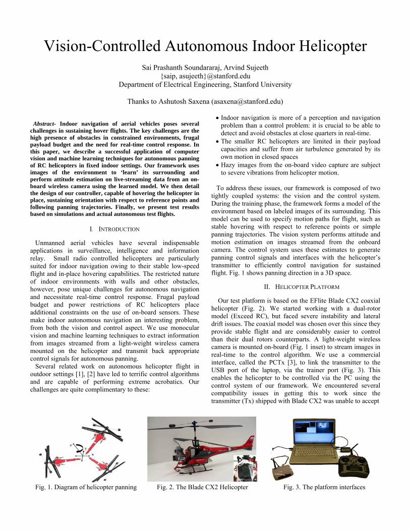
Thanks to Ashutosh Saxena ([email protected]) Abstract- Indoor navigation of aerial vehicles poses several challenges in sustaining hover flights. The key challenges are the high presence of obstacles in constrained environments, frugal payload budget and the need for real-time control response. In this paper, we describe a successful application of computer vision and machine learning techniques for autonomous panning of RC helicopters in fixed indoor settings. Our framework uses images of the environment to ‘learn’ its surrounding and perform attitude estimation on live-streaming data from an on-board wireless camera using the learned model. We then detail the design of our controller, capable of hovering the helicopter in place, sustaining orientation with respect to reference points and following panning trajectories. Finally, we present test results based on simulations and actual autonomous test flights.
I. INTRODUCTION Unmanned aerial vehicles have several indispensable applications in surveillance, intelligence and information relay. Small radio controlled helicopters are particularly suited for indoor navigation owing to their stable low-speed flight and in-place hovering capabilities. The restricted nature of indoor environments with walls and other obstacles, however, pose unique challenges for autonomous navigation and necessitate real-time control response. Frugal payload budget and power restrictions of RC helicopters place additional constraints on the use of on-board sensors. These make indoor autonomous navigation an interesting problem, from both the vision and control aspect. We use monocular vision and machine learning techniques to extract information from images streamed from a light-weight wireless camera mounted on the helicopter and transmit back appropriate control signals for autonomous panning. Several related work on autonomous helicopter flight in outdoor settings [1], [2] have led to terrific control algorithms and are capable of performing extreme acrobatics. Our challenges are quite complimentary to these:
• Indoor navigation is more of a perception and navigation problem than a control problem: it is crucial to be able to detect and avoid obstacles at close quarters in real-time.
• The smaller RC helicopters are limited in their payload capacities and suffer from air turbulence generated by its own motion in closed spaces
• Hazy images from the on-board video capture are subject to severe vibrations from helicopter motion.
To address these issues, our framework is composed of two tightly coupled systems: the vision and the control system. During the training phase, the framework forms a model of the environment based on labeled images of its surrounding. This model can be used to specify motion paths for flight, such as stable hovering with respect to reference points or simple panning trajectories. The vision system performs attitude and motion estimation on images streamed from the onboard camera. The control system uses these estimates to generate panning control signals and interfaces with the helicopter’s transmitter to efficiently control navigation for sustained flight. Fig. 1 shows panning direction in a 3D space.
II. HELICOPTER PLATFORM
Our test platform is based on the EFlite Blade CX2 coaxial helicopter (Fig. 2). We started working with a dual-rotor model (Exceed RC), but faced severe instability and lateral drift issues. The coaxial model was chosen over this since they provide stable flight and are considerably easier to control than their dual rotors counterparts. A light-weight wireless camera is mounted on-board (Fig. 1 inset) to stream images in real-time to the control algorithm. We use a commercial interface, called the PCTx [3], to link the transmitter to the USB port of the laptop, via the trainer port (Fig. 3). This enables the helicopter to be controlled via the PC using the control system of our framework. We encountered several compatibility issues in getting this to work since the transmitter (Tx) shipped with Blade CX2 was unable to accept
Fig. 1. Diagram of helicopter panning Fig. 2. The Blade CX2 Helicopter Fig. 3. The platform interfaces

PPM signals from the trainer port, which is what PCTx uses to communicate with the Tx. We now use the Spektrum DX6i Tx, which is capable of translating PPM input to DSM signals for controlling the helicopter.
III. CONTROLLER FRAMEWORK
We use techniques from computer vision and machine learning to be able to quickly and reliably get an estimate of our current position and velocity. We chose the K-Nearest Neighbors (kNN) algorithm to classify a frame with respect to its attitude because it is a fast, simple, data-driven approach. However, this alone is insufficient for fine-grained navigation and stability. We calculate optical flow to measure the relative velocity from frame to frame. Our goal is to combine these estimates to produce sensitive control signals capable of sustaining autonomous panning flight. Fig. 5 shows the block diagram for the navigation system. The right side shows the control path for live helicopter flight, while the left side shows the control flow for the virtual controller, discussed in section IV. A. Training the Model In the training phase we attempt to learn a model of the environment. The choice of a constrained setting is an important factor; an environment that is too dynamic (varying from day to day tests) will perform poorly. We began with a training set taken along an oval in the AI Lab. A training video is taken at each point by one of us holding the helicopter facing a fixed reference point and rotating 360 degrees. Each frame in a video is then labeled using its angle w.r.t. a reference point.
360
This procedure has some weaknesses. First, data collection can be a slow process if there are many points in the environment. Second, it is difficult for a human to rotate at a uniform velocity. Lastly, the AI lab has many students and many gadgets in a state of flux. To address some of these problems, in the second half of the quarter we moved our training environment to the 4th floor of Gates, just outside of the elevators (Fig. 4).
Fig. 4. The training environment
Fig. 5. Control flow diagram
This is an open space suitable for initial testing that does not change much from day to day. We collected two sets of training data along and within circles of varying radii, each at a different height. For each point, we took a video rotating first in the clockwise direction and then in the counter-clockwise direction; we hypothesized that this would help marginalize some of the human error involved from point to point. We also experimented with methods of removing human action from the process by rotating the helicopter on a turntable, but found that we were unable to slow the rotation to a satisfactory speed. Our final training dataset consisted of 70 videos and 16089 frames (each frame is 640 x 480). As this is a large amount of data, we originally resized each frame to 50x50 to meet memory and speed constraints for real-time processing. Eventually, we found that we could improve our results by using Principal Components Analysis (PCA) to reduce each frame's dimensionality from 307200 to 10. PCA was implemented using OpenCV's computationally efficient built-in eigen objects and eigen projections. Instead of arbitrarily re-scaling the image, using PCA also helped us reduce the classification's sensitivity to noise perturbations and height variations. Finally, we trained the K Nearest Neighbor's model on the projected data using OpenCV's built-in KNN implementation. B. Attitude and Velocity Estimation When a new frame is received from the helicopter's wireless camera, we extract the K nearest neighbors from its PCA projection. We incorporate the image history on the last five

Fig. 6. Visualization of optical flow with attitude inset
classifications to select the closest prediction (i.e. predictions of the previous five frames are used to find the closest match from among the K results), and that is output as the prediction of current attitude. Optical flow is applied on the original full-sized frame to give us a measure of which direction the helicopter is moving in. This velocity estimate will be fed into the control algorithm and used to refine the magnitude of the turn command generated. This provides a counter-acting effect that helps prevent the helicopter from turning too drastically. Optical flow is implemented using 400 features and OpenCV's Pyramidal Lucas Kanade (PLK) algorithm [4]. We calculate the total optical flow as the mean over all the features for each frame, with respect to the horizontal direction only. Finally, we apply a median-mean filter to smooth the optical flow values over time. Fig. 6 shows the calculated optical flow on a frame, and the inset shows the attitude estimated by kNN. B. Control Algorithm We propose an algorithm to combine the optical flow result with the K nearest neighbor classification to produce an updated attitude estimate for each frame. The update equation is given as follows: TurnCmd = max(min( + ( − ), P_TH), N_TH) where is the velocity estimate calculated by optical flow, is the desired angle we wish to navigate to, is our current estimate from kNN. and are constants used to account for time and tune the result. We can alter as a function of time to make the helicopter follow a particular trajectory at fixed altitude. TurnCmd is the control signal generated by the algorithm, which is passed on to the transmitter to autonomously control the helicopter panning. The TurnCmd value is clipped to lie between the negative and positive threshold, N_TH and P_TH, to avoid over-controlling.
IV. CONTROLLER INTERFACE AND SIMULATOR A. Controller Interface We have developed a functional GUI framework for remotely controlling the RC helicopter. Our framework is built on top of the OpenCV library and Endurance's low level PCTx driver. It was designed to provide us flexibility in running experiments, smooth control of navigation and effective real-time feedback. It also serves as the UI for training and running the simulator. The controller maps the transmitter controls to intuitive keyboard presses, allowing the user to easily control the helicopter in real-time. It is multi-threaded with non-blocking I/O to ensure responsiveness. With a single key press, the user can transfer control of the rudder (for panning) to the already running Vision Control algorithm, while continuing to control the throttle, aileron, and elevator from the keyboard. To prevent the helicopter from receiving wild swings in control signals which could damage its gears, the controller has a configurable maximum change per channel per time step. The frequency of updated channel values being transmitted to the helicopter is also configurable from the interface. Fig. 7 shows a screenshot of the controller during an actual flight. The display presents several pertinent real-time results to the user: the current desired and actual channel values, the video stream from helicopter's wireless camera, a radar displaying the current desired panning angle and actual kNN estimate, and trackbars showing the kNN estimate, optical flow values, and turn command generated by the control algorithm. B. Simulator We implemented a simple simulator, or virtual controller, to verify our framework. The virtual controller forms a map of the surrounding based on the test videos. It interacts with the vision and control framework by accepting a turn control command, retrieving the image frame that would have resulted if the command was issued to the helicopter in the actual setting, and passing that on to the controller. This allows for simulating panning trajectories and visualizing the controller's dynamics. The simulator was used extensively in the testing of our system framework.
Fig. 7. Screenshot of the controller interface

A. Ftraisimconblubotbetfromredoutto l
Simulator ReFig. 8 and Fig.ining and a tes
mple trajectory.ntinuous panninue lines in the fth training videtter because alm the videos t
duces the numtside of the trailive test flight r
Fig. 8. S
Fig. 9
V. Results . 9 show resulst video respec. In these testsng back and fofigure). The coeo and test vidll of the framtaken by us romber of miscined area and aresults.
Simulator resul
9. Simulator res
RESULTS
lts of using thctively, while trs, the trajectoryorth from 0° toontroller perfordeos. The simu
mes being classotating in a circlassifications altitude variatio
lts for a trainin
sults for a test v
e simulator onrying to followy was defined o 120° (shown rms quite well ulated results asified are drawrcle. This greadue to drifti
ons, as compar
ng video
video
n a w a
as as on are wn
atly ing red
The fioutliersor lackthese mthey artrajecto B. Te The eoutsidewas semcontroladjustea relativrudder rudder key to tbased c We cand pofound approprare shosustain the strato this able topoint, aslice ostably classify Whiletrends output desireddecreas
figures do, hs. These can bek of features imisclassificatiore a contributiory in actual tes
est Flight Resulexperiments w
e the elevators mi-autonomoulling the helicoed the values ovely stable hovtrim for the cthe algorithm transfer autonocontrol algorithhose a minimu
ositive thresho 0.1
riately scaled own in Fig. 1
orientation waight blue line)position and h correctly idenand pan towarf time (about hovering at th
ying it, before de these resultsare encouraginfor a few fra
d angle (210°)ses as we expec
Fig. 10. R
however, showe attributed to iin the frame tons occur evening factor for st flights.
lts were conducted
on the 4th floous; we began bopter using ouf each channelver was achievontrol algorithconsiders to b
omous control hm. um threshold tuold (P_TH) o1 and turn command10. For this te
with respect to ). Ideally, we shover in its vintify the generrds that. The 20 seconds)
he desired angdeviating aways are less thanng. Table 1 sames. As the ), the magnituct.
Real results fro
w some miscissues such as no classify it d
n in the idealizedeviance from
d in our fixed or of Gates. Eaby manually liur controller inl trim signal med. At this poin
hm; this is the be stable. We of the rudder t
urn command (of +1, and ex 0.03 to corre
d. kNN results est flight, we a point at 210should be ableicinity. Our heral direction oencircled sectwhere the he
gle and kNN wy. n exceptional,hows the actuhelicopter app
ude of the tur
om a trial flight
classification noisy images
distinctly. As ed simulator,
m the desired
environment ch trial flight fting off and nterface. We
manually until nt, we set the value of the then press a
to the vision-
(N_TH) of -1 xperimentally espond to an for one trial intended to
0° (shown by e to converge elicopter was
of the desired tion shows a elicopter was was correctly
, the general ual controller proaches the rn command
t

TABLE I Snippet from test flight
Unfortunately, we see a sudden discontinuity in classification, which is a recurring problem. Since the misclassification is consistent over several frames, we believe that this problem can be characterized as misclassification due to drift, and occurs because as the helicopter turns it also drifts farther away from the known environment (i.e. outside the training circle). One way of mitigating this problem is to learn how changing one trim affects another (trim correlations) and adjust accordingly while turning to maintain a drift-free hover. Another method is to collect more training videos at more points in the fixed environment. Our results also reveal that the number of recorded frames is actually less than our targeted frame rate (30 fps); this shows that we are not actually processing in real-time, and are dropping frames. While it is unlikely that this has a significant impact on the results, it is an issue that requires further investigation. Videos from our experiments are available online at www.stanford.edu/~saip/heli.html. They show both an external view of the helicopter navigating as well as an internal view of the controller and helicopter camera. It is particularly striking to see the frequency of noise in the camera stream, a consistent source of misclassifications and poor optical flow values.
VI. CONCLUSION AND FUTURE WORK Our work demonstrates enough potential to conclude that a vision-based control algorithm, with appropriate training data and tuning, can autonomously pan an RC helicopter to a desired angle. We have developed a control framework for running experiments that can be used as a foundation for extending this work to other aspects of indoor helicopter autonomous navigation. There are several key challenges remaining that we hope to continue to pursue after this quarter ends: first, learning trim correlations to combat the problem of misclassification due to drift; second, being able to accurately follow a live panning trajectory; third, extending autonomous navigation capabilities to the aileron, elevator, and throttle channels; and finally incorporating methods for obstacle avoidance.
VII. ACKNOWLEDGMENTS
We would like to express our sincere gratitude to Ashutosh Saxena and Prof. Andrew Ng for their invaluable comments,
discussions and helpful insights throughout the course of this project.
VIII. REFERENCES [1] G. Eason, B. Noble, an[1] Andrew Y. Ng, H. Jin Kim, Michael I. Jordan
and Shankar Sastry, Autonomous helicopter flight via reinforcement learning. In the 17th Annual Conference on Neural Information Processing Systems (NIPS, 2003)
[2] Pieter Abbeel, Adam Coates, Morgan Quigley and Andrew Y.Ng, An application of reinforcement learning to acrobatic helicopter flight. In Proceedings of Neural Information Processing Systems 2007
[3] www.endurance-rc.com/pctx.html [4] Optical flow implementation from OpenCV library and template
code from David Stavens (Stanford AI lab).
Desired Angle
kNN Estimate
Optical Flow TurnCmd
210 202.5 10.49 -0.92 210 202.5 7.56 -0.87 210 202.5 7.23 -0.82 210 204.0 5.85 -0.79 210 115.54 3.75 -0.59 210 113.86 -5.59 -0.39 210 113.86 -1.68 -0.19 210 113.86 -3.11 0.014 210 112.19 -2.49 0.211