vision for robotic object manipulation in domestic settingscelle/papers/kragic_ras05.pdf ·...
TRANSCRIPT

PR
OO
F
6
Robotics and Autonomous Systems xxx (2005) xxx–xxx
Vision for robotic object manipulation in domestic settings3
Danica Kragic∗, Marten Bjorkman, Henrik I. Christensen, Jan-Olof Eklundh4
Computer Vision and Active Perception Lab, Centre for Autonomous Systems, Royal Institute of Technology, Stockholm, Sweden5
Received 5 March 2005; accepted 21 March 2005
6
Abstract7
In this paper, we present a vision system for robotic object manipulation tasks in natural, domestic environments. Givencomplex fetch-and-carry robot tasks, the issues related to the wholedetect-approach-grasploop are considered. Our visionsystem integrates a number of algorithms using monocular and binocular cues to achieve robustness in realistic settings. Thecues are considered and used in connection to both foveal and peripheral vision to provide depth information, segmentation of theobject(s) of interest, object recognition, tracking and pose estimation. One important property of the system is that the step fromobject recognition to pose estimation is completely automatic combining both appearance and geometric models. Experimentalevaluation is performed in a realistic indoor environment with occlusions, clutter, changing lighting and background conditions.
8
9
10
11
12
13
14
© 2005 Elsevier B.V. All rights reserved.15
Keywords:Cognitive systems; Object recognition; Service robots; Object manipulation16
17
118
19
t20
i21
p22
w23
m24
f25
b26
p27
c(
s on28
per-29
our30
en31
f ev-32
hing33
ires34
t—35
ion36
ing37
t the38
39
ion40
is 41
42
v- 43
1 02 d
UN
CO
RR
EC
TED
ROBOT 1235 1–1
. Introduction
One of the key components of a robotic systemhat operates in a dynamic, unstructured environments robust perception. Our current research considers theroblem of mobile manipulation in domestic settingshere, in order for the robot to be able to detect andanipulate objects in the environment, robust visual
eedback is of key importance. Humans use visual feed-ack extensively toplanandexecuteactions. However,lanning and execution is not a well-defined one-way
∗ Corresponding author. Tel.: +46 87906729; fax: +46 87230302.E-mail addresses:[email protected] (D. Kragic);
[email protected] (M. Bjorkman); [email protected]. Christensen); [email protected] (J.-O. Eklundh).
stream: how we plan and execute actions dependwhat we already know about the environment we oate in, what we are about to do, and what we thinkactions will result in. Complex coordination betwethe eye and the hand is used during execution oeryday activities such as pointing, grasping, reacor catching. Each of these activities or actions requattention to different attributes in the environmenwhile pointing requires only an approximate locatof the object in the visual field, a reaching or graspmovement requires more exact information abouobject’s pose.
In robotics, the use of visual feedback for motcoordination of a robotic arm or platform motiontermedvisual servoing, Hutchinson et al.[1]. In gen-eral, visual information is important at different le
921-8890/$ – see front matter © 2005 Elsevier B.V. All rights reserved.oi:10.1016/j.robot.2005.03.011

T P
RO
OF
6
2 D. Kragic et al. / Robotics and Autonomous Systems xxx (2005) xxx–xxx
els of complexity: from scene segmentation to object’s44
pose estimation. Hence, given a complex fetch-and-45
carry type of task, issues related to the wholedetect-46
approach-grasploop have to be considered. Most vi-47
sual servoing systems, however, deal only with theap-48
proachstep and disregard issues such asdetectingthe49
object of interest in the scene or retrieving its three50
dimensional (3D) structure in order to perform grasp-51
ing. A so calledteach-by-showingapproach is typi-52
cally used where the desired camera placement with53
respect to the object is well defined and known before54
hand.55
Our goal is the development of an architecture that56
integrates different modules where each module en-57
capsulates a number of visual algorithms responsi-58
ble for a particular task such as recognition or track-59
ing. Our system is heavily based on theactive vi-60
sionparadigm, Ballard[2] where, instead of passively61
observing the world, viewing conditions are actively62
changed so that the best results are obtained given a63
task at hand.64
In our previous work, Bjorkman and Kragic[3] we65
have presented a system that consists of two pairs of66
stereo cameras: a peripheral camera set and a foveal67
one. Recognition and pose estimation are performed68
using either one of these, depending on the size and69
distance to the object of interest. From segmentation70
based on binocular disparities, objects of interest are71
found using the peripheral camera set, which then trig-72
gers the system to perform a saccade, moving the ob-73
j us a74
c es-75
o m et76
a and77
s en-78
t lar79
c r, we80
f ect81
t to82
d83
84
a t85
o ec-86
t ion87
w b-88
j g89
u rasp-90
i is91
presented in Section8 and final conclusion given in 92
Section9. 93
2. Problem definition 94
In general, vision based techniques employed in vi-95
sual servoing and object manipulation depend on:96
• Camera placement: Most visual servoing systems97
today useeye-in-handcameras and deal mainly with 98
theapproachobject step in ateach-by-showingman- 99
ner, Malis et al.[5]. In our approach, we consider a100
combination of a stand-alone stereo and an eye-in-101
hand camera systems, Kragic and Christensen[6]. 102
• Number of cameras: In order to extract metric103
information, e.g. sizes and distances, about objects104
observed by the robot, we will show how we can105
benefit from binocular information. The reason for106
using multiple cameras in our system is the fact that107
it simplifies the problem of segmenting the image108
data into different regions representing objects in a109
3D scene. This is often referred to asfigure-ground 110
segmentation. In cluttered environments and com-111
plex backgrounds, figure-ground segmentation is112
particularly important and difficult to perform and113
commonly the reason for experiments being per-114
formed in rather sparse, simplified environments.115
In our work, multiple cameras are used for scene116
segmentation while a single camera is used for117
visual servoing, object tracking and recognition. 118
• sing119
pe-120
ork121
nity,122
n- 123
eral124
bject125126
I sks127
s ick128
u k or129
c ay130
b ned131
s ernal132
r 133
j n in134
F bot135
l e and136
UN
CO
RR
EC
ect into the center of foveal cameras achieving thombination of a large field of view and high image rlution. Compared to one of the recent systems, Kil. [4], our system uses both hard (detailed models)oft modeling (approximate shape) for object segmation. In addition, choice of binocular or monocuues is used depending on the task. In this papeormalize the use of the existing system with respo Fig. 1—how to utilize the system with respectifferent types of robotic manipulation tasks.
This paper is organized as follows. In Section2,problem definition is given. In Section3, a shor
verview of the current system is given and in Sion 4 hypotheses generation is presented. In Sect5e deal with the problem of manipulating known o
ects and in Section6with the problem of manipulatinnknown objects. Some issues related to object g
ng are given in Section7. Experimental evaluation
ED
ROBOT 1235 1–1
Camera type: Here we consider systems uzooming cameras or combinations of foveal andripheral ones. With respect to these, very little whas been reported in visual servoing commuBenhimane and Malis[7]. In this paper, we demostrate how a combination of foveal and periphcameras can be used for scene segmentation, orecognition and pose estimation.
n our current system, the robot may be given tauch as “Robot, bring me the raisins” or “Robot, pp this”. Depending on the prior information, i.e. tasontext information, different solution strategies me chosen. The first task of the above is well defiince it assumes that the robot already has the intepresentation of the object, e.g. theidentityof the ob-ect is known. An example of such a task is showig. 2: after being given a spoken command, the ro
ocates the object, approaches it, estimates its pos

CT
PR
OO
F
D. Kragic et al. / Robotics and Autonomous Systems xxx (2005) xxx–xxx 3
Fig. 1. Robotic manipulation scenarios.
finally performs grasping. More details related to this137
approach are given in Section5. For the second task, the138
spoken command is commonly followed by a pointing139
gesture—here, the robot does not know theidentityof140
the object, but it knows its approximatelocation. The141
approach considered in this work is presented in Sec-142
tion 6. Fig. 1shows different scenarios with respect to143
prior knowledge of objectidentityand location, with144
the above examples shaded. A different set of underly-145
Fig. 2. Detect-approach-grasp example.
c Tech
ing visual strategies is required for each of these sce-146
narios. We have considered these two scenarios since147
they are the most representative examples for robotic148
fetch-and-carry tasks. 149
2.1. Experimental platform 150
The experimental platform is a Nomadic Technolo-151
gies XR4000, equipped with a Puma 560 arm for ma-152
nipulation (seeFig. 3). The robot has sonar sensors, a153
SICK laser scanner, a wrist mounted force/torque sen-154
sor (JR3), and a color CCD camera mounted on the155
Barrett Hand gripper. The palm of the Barrett hand is156
covered by a VersaPad touch sensor and, on each fin-157
ger, there are three Android sensors. On the robot’s158
shoulder, there is a binocular stereo-head. This sys-159
tem, known as Yorick, has four mechanical degrees of160
freedom; neck pan and tilt, and pan for each camera in161
relation to the neck. The head is equipped with a pair of
OR
RE
Fig. 3. (Left) Experimental platform Nomadi
UN
C
ED
nologies XR4000, and (Right) Yorick stereo-head.
ROBOT 1235 1–16

T P
RO
OF
6
4 D. Kragic et al. / Robotics and Autonomous Systems xxx (2005) xxx–xxx
Sony XC999 cameras, with focal length of 6 mm. Ad-162
ditional pair of Sony XC999 cameras with focal length163
of 12 mm is placed directly on the robot base.164
For some of the experimental results that will be pre-165
sented further on, a stand-alone binocular stereo-head166
system shown inFig. 3 was used. Here, the head is167
equipped with two pairs of Sony XC999 cameras, with168
focal lengths 28 and 6 mm, respectively. The motiva-169
tion for this combination of cameras will be explained170
related to the examples.171
3. The system172
Fig. 4 shows a schematic overview of the basic173
building blocks of the system. These blocks do not nec-174
essarily correspond to the actual software components,175
but are shown in order to illustrate the flow of informa-176
tion through the system. For example, the visual front177
end consists of several components, some of which are178
running in parallel and others hierarchically. For ex-179
ample, color and stereo information are extracted in180
parallel, while epipolar geometry has to be computed181
prior to disparities. On the other hand, action genera-182
tion, such as initiating 2D or 3D tracking, is distributed183
and performed across multiple components.184
The most important building blocks can be summa-185
rized as follows:186
• The Visual Front-End is responsible for the ex-187
traction of visual information needed for figure-188
ground segmentation and other higher level proce-189
sses. 190
• Hypotheses Generation produces a number of hy-191
potheses about the objects in the scene that may be192
relevant to the task at hand. The computations are193
moved from being distributed across the whole im-194
age to particular regions of activation. 195
• Recognition is performed on selected regions, using196
either corner features or color histograms, to deter-197
mine the relevancy of observed objects. 198
• Action Generation triggers actions, such as visual199
tracking and pose estimation, depending on the out-200
come of the recognition and current task specifica-201
tion. 202
Due to the complexity of the software system, it203
was partitioned into a number of smaller modules204
that communicate through a framework built on a205
interprocess communication standard called CORBA206
(Common Object Request Broker Architecture),207
Vinoski [8]. The current version of the system consists208
of about ten such modules, each running at a different209
frame rate. The lowest level frame grabbing module210
works at a frequency of 25 Hz, while the recognition211
module is activated only upon request. In order to212
consume processing power, modules are shut down213
temporarily when not been accessed by any other214
module within a time frame of 10 s. 215
With limited resources in terms of memory storage216
and computational power, biological and robotic sys-217
ding bl
UN
CO
RR
EC
Fig. 4. Basic buil
ED
ROBOT 1235 1–1
ocks of the system.
CT
PR
OO
F
6
D. Kragic et al. / Robotics and Autonomous Systems xxx (2005) xxx–xxx 5
tems need to find an acceptable balance between the218
width of the visual field and its resolution. Otherwise,219
the amount of visual data will be too large for the sys-220
tem to efficiently handle. Unfortunately, this balance221
depends on the tasks the systems have to perform. An222
animal that has to stay alert in order to detect an ap-223
proaching predator, would prefer a wide field of view.224
The opposite is true if the same animal acts as a preda-225
tor itself. Similarly, a robotic system benefits from a226
wide field of view, in order not to collide with obsta-227
cles while navigating through a cluttered environment.228
A manipulation task on the other hand, requires a high229
resolution in order grasp and manipulate objects. That230
is, to find objects in the scene a wide field of view is231
preferable, but recognizing and manipulating the same232
objects require a high resolution.233
On a binocular head, Bjorkman and Kragic[3] we234
overcame this problem by using a combination of two235
pairs of cameras, a peripheral set for attention and a236
foveated one for recognition and pose estimation. In237
order to facilitate transfers of object hypotheses from238
one pair to the other, and replicate the nature of the hu-239
man visual system, the pairs were placed next to each240
others. The camera system on the robot is different in241
that the two pairs are widely separated and placed on242
an autonomously moving platform, seeFig. 3: a stereo243
head on a shoulder and another pair on the base. The244
search pair is located on-top of the robot overlooking245
the scene and the manipulation pair is at waist height,246
such that the gripper will not occlude an object while it247
i th-248
e tures249
a lated250
p riph-251
e f the252
f253
si-254
b eras255
s s be-256
t r of257
f ture258
s ery259
d ng.260
I ove261
t by262
t tion263
p tely264
k re-265
lation to the base. Hypotheses are found by the search266
pair, the 3D positions are derived using triangulation267
and finally projected onto the image planes of the ma-268
nipulation pair. For the 3D position to be accurately269
estimated, the search pair is calibrated on-line, simi-270
larly to the original version of the system, Bjorkman 271
and Eklundh[9]. The precision in depth ranges from272
about a decimeter to half a meter depending on the273
observed distance. 274
3.1. Stereo system modeling—epipolar geometry 275
With a binocular set of cameras, differences in276
position between projections of 3D points onto the277
left and right image planes (disparities) can be used278
to perform figure-ground segmentation and retrieve279
the information about three-dimensional structure280
of the scene. If the relative orientation and position281
between cameras is known, it is possible to relate282
these disparities to actual metric distances. One of the283
commonly used settings is where the cameras are rec-284
tified and their optical axes mutually parallel, Kragic285
and Christensen[6]. However, one of the problems286
arising is that the part of the scene contained in the287
field of view of both cameras simultaneously is quite288
limited. 289
Another approach is to estimate the epipolar geom-290
etry continuously from image data alone, Bjorkman 291
[10]. Additional reason for this may be that small distur-292
b gnifi-293
c fact,294
a eral295
c ere-296
f ipo-297
l rner298
f s 299
a ages300
u an-301
g d 302
t 303(304
w si-305
t m-306
b , 307
a 308
UN
CO
RR
E
s being manipulated. In the original version, hyposis transfers were based on matched corner feand affine geometry. Hence, with the cameras reairwise, the position of hypotheses seen by the peral cameras could be transferred to the images o
oveated stereo set.This way of transferring positions is no longer fea
le in the robot camera configuration. With the cameparated by as much as a meter, the intersectionween visual fields tend to be small and the numbeeatures possible to match is low. Furthermore, a feaeen from two completely different orientations is vifficult to match, even using affine invariant matchi
nstead we exploit the fact that we can actively mhe platform such that an object of interest, foundhe search pair, will become visible by the manipulaair. For this to be possible we have to approximanow the orientation and position of the cameras in
ED
ROBOT 1235 1–1
ances such as vibrations and delays introduce siant noise to the estimation of the 3D structure. Inn error of just one pixel leads to depth error of seventimeters on a typical manipulation distance. Thore, for some of the manipulation tasks, the epar geometry is estimated robustly using Harris’ coeatures, Harris and Stephens[11]. Such corner featurere extracted and matched between the camera imsing normalized cross-correlation. The vergenceleα, gaze directiont, relative tiltrx and rotation aroun
he optical axesrz, are iteratively sought using
dx
dy
)=(
(1 + x2)α − yrz
xyα + ry + xrz
)+ 1
Z
(1 − xt
−yt
), (1)
hereZ is the unknown depth of a point at image poion (x, y). The optimization is performed using a coination of RANSAC[12] for parameter initializationnd M-estimators[13] for improvements.

T P
RO
OF
6
6 D. Kragic et al. / Robotics and Autonomous Systems xxx (2005) xxx–xxx
This optical flow model[14] is often applied to mo-309
tion analysis, but has rarely been used for stereo. The310
reason for this is because the model is approximate311
and only works for relatively small displacements. In312
our previous work we have, however, experimentally313
shown that this model is more robust than the essential314
matrix in the case of binocular stereo heads, Bjorkman315
and Eklundh[9], even if the essential matrix leads316
to a more exact description of the epipolar geometry,317
Longuet-Higgins[15].318
4. Hypotheses generation319
The purpose of this component is to derive quali-320
fied guesses ofwherethe object of interest is located321
in the current scene. As mentioned earlier, this step322
is performed using the peripheral cameras while the323
recognition module uses the foveal ones. This requires324
a transfer from peripheral to foveal vision, or from dis-325
tributed to focused attention Palmer[16].326
4.1. Distributed attention327
Unlike focused attention, distributed attention328
works on the whole image instead of being con-329
centrated to a particular image region. Using the330
available visual cues a target region, that might331
represent an object of interest, is identified. Even if the332
current system is limited to binocular disparities, it is333
s the334
m ed335
o ma-336
t ially337
i lor338
o e is339
n340
he-341
s inter-342
e a set.343
M be344
f345
c hin a346
s347
t left348
p then349
g sian350
fi lter351
is set so as to maximize the response of image blobs352
representing objects of the requested size and distance.353
The depth range is continuously updated so that hy-354
potheses are obtained for objects at different depths.355
In our system, the depths typically vary between 1 and356
3 m. 357
4.2. Focused attention 358
From the generated hypotheses, a target region is359
selected so that the gaze can be redirected and recog-360
nition performed using the foveal cameras. This se-361
lection is done automatically from the hypothesis of362
largest strength. However, before the strongest hy-363
pothesis is selected, a small amount of noise equiva-364
lent to about 20% of the largest possible strength is365
added. This is done in order to prevent the system366
from getting stuck at a local maximum. Due to occlu-367
sions, the requested object might otherwise never be368
visited. 369
Since hypotheses are described in the peripheral370
cameras frame and recognition is performed using the371
foveal ones, the relative transformations have to be372
known. These are found applying a similarity model373
to a set of Harris’ corner features similar to those used374
for epipolar geometry estimation in Section3.1. On 375
the stereo head system shown inFig. 3, the relative 376
rotations, translations and scales are continuously377
updated at a rate of about 2 Hz. For the manipulator378
system, the robot first has to rotate its base while379
t lap.380
K late381
t era382
f 383
the384
f gion,385
t ple386
o is387
c shift388
a - 389
d und390
t ap.391
T the392
t two393
i in394
t ade.395
T to the396
r 397
UN
CO
RR
EC
traightforward to add additional cues, such as inodel of Itti et al.[17]. Here, we have concentratn disparities because they contain valuable infor
ion about object size and shape. This is especmportant in a manipulation task, where the cof an object might be irrelevant, whereas the sizot.
The only top-down information needed for hypotes generation is the expected size of an object ofst and the approximate distance from the camerore information about the attention system can
ound in Bjorkman and Eklundh[18]. A binary map isreated containing those points that are located witpecified depth range. The third column ofFig. 9showswo such maps overlaid on-top of the correspondingeripheral images. Initial hypotheses positions areenerated from the results of a difference of Gauslter applied to the binary map. The scale of this fi
ED
ROBOT 1235 1–1
racking the hypotheses until visual fields overnowing the transformations, it is possible to trans
he hypotheses positions into the foveal camrames.
Before a saccade is finally executed, fixatingoveal cameras onto the selected hypothesis rehe target position is refined in 3D. During a couf image frames, a high-resolution disparity mapalculated locally around the target area. A meanlgorithm, Comaniciu et al.[19], is run iteratively upating the position from the cluster of 3D points aro
he target position, represented by the disparity mhe maximum size of this cluster is specified using
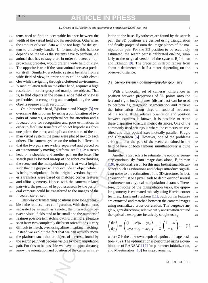
op-down information mentioned above. The firstmages ofFig. 5 show these clusters highlightedhe left peripheral images before and after a sacche foveal images after the saccade can be seenight.
EC
TED
PR
OO
F
6
D. Kragic et al. / Robotics and Autonomous Systems xxx (2005) xxx–xxx 7
Fig. 5. The first two images show a target region before and after a saccade (the rectangles show the foveal regions within the left peripheralcamera image) and the foveal camera images after executing a saccade are shown in the last two images.
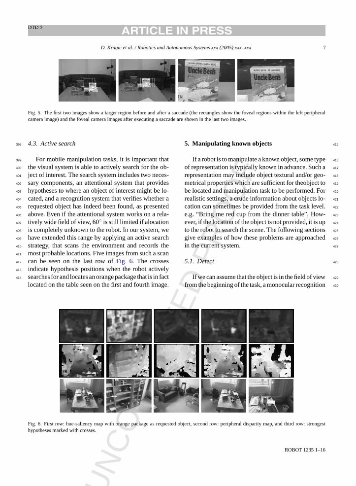
4.3. Active search398
For mobile manipulation tasks, it is important that399
the visual system is able to actively search for the ob-400
ject of interest. The search system includes two neces-401
sary components, an attentional system that provides402
hypotheses to where an object of interest might be lo-403
cated, and a recognition system that verifies whether a404
requested object has indeed been found, as presented405
above. Even if the attentional system works on a rela-406
tively wide field of view, 60◦ is still limited if alocation407
is completely unknown to the robot. In our system, we408
have extended this range by applying an active search409
strategy, that scans the environment and records the410
most probable locations. Five images from such a scan411
can be seen on the last row ofFig. 6. The crosses412
indicate hypothesis positions when the robot actively413
searches for and locates an orange package that is in fact414
located on the table seen on the first and fourth image.
5. Manipulating known objects 415
If a robot is to manipulate a known object, some type416
of representation is typically known in advance. Such a417
representation may include object textural and/or geo-418
metrical properties which are sufficient for theobject to419
be located and manipulation task to be performed. For420
realistic settings, a crude information about objects lo-421
cation can sometimes be provided from the task level.422
e.g. “Bring me red cup from the dinner table”. How-423
ever, if the location of the object is not provided, it is up424
to the robot to search the scene. The following sections425
give examples of how these problems are approached426
in the current system. 427
5.1. Detect 428
If we can assume that the object is in the field of view429
from the beginning of the task, a monocular recognition430
F equest : strongesth
UN
CO
RR
ig. 6. First row: hue-saliency map with orange package as rypotheses marked with crosses.
ROBOT 1235 1–1
ed object, second row: peripheral disparity map, and third row
T P
RO
OF
6
8 D. Kragic et al. / Robotics and Autonomous Systems xxx (2005) xxx–xxx
system can be used to locate the object in the image,431
Zillich et al. [20].432
However, when a crude information about object’s433
current position is not available, detecting a known ob-434
ject is not an easy task since a large number of false435
positives can be expected. Candidate locations have to436
be analyzed in sequence which may be computationally437
too expensive, unless the robot has an attentional sys-438
tem that delivers the most likely candidate locations439
first, using as much information about the requested440
object as possible.441
A natural approach here is to employ a binoc-442
ular system that provides metric information as an443
additional cue. Since the field of view of a typical444
camera is quite limited, binocular information can445
only be extracted from those parts of the 3D scene446
that are covered by both cameras’ peripheral field of447
view. In order to make sure that an object of inter-448
est is situated in the center of each camera’s field of449
view, the head is able to actively change gaze direc-450
tion and vergence angle, i.e. the difference in orienta-451
tion between the two cameras. In our system, stereo452
based figure-ground segmentation is intended for mo-453
bile robot navigation and robot arm transportation to454
the vicinity of the object. More detailed information455
about an object’s pose is provided using a monocu-456
lar model based pose estimation and tracking, Kragic457
[21].458
The visual front-end is responsible for delivering 3D459
data about the observed scene. Such information is ex-460
t s the461
a age462
r ps.463
T at a464
r and465
u ter-466
p ys-467
t -468
o age469
p per-470
f fore471
d in-472
c im-473
p d474
g475
b d, is476
t ac-477
c ant,478
the computational cost of these methods makes them479
infeasible for our particular application which means480
that correlation based methods are typically used in481
practice. Currently, we use two kinds of visual cues482
for this purpose, 3D size and hue histograms using483
the procedure described in Section4.1. These cues 484
were chosen since they are highly object dependent485
and relatively insensitive to changing lighting condi-486
tions, object pose and viewing direction. The images487
in Fig. 6 show examples where the orange package488
is requested. The upper images illustrate the saliency489
maps generated using the hue histograms of this ob-490
ject. From the disparity maps (second row) a number491
of candidate locations are found, as shown in the last492
row. 493
We further use recognition to verify that a requested494
object has indeed been found. With attention and recog-495
nition applied in a loop, the system is able to automat-496
ically search the scene for a particular object, until it497
has been found by the recognition system. Two recog-498
nition modules are available for this purpose: (i) a fea-499
ture based module based on Scale Invariant Feature500
Transform (SIFT) features Lowe[24], and (ii) an ap- 501
pearance based module using color histograms, Ekvall502
et al.[25]. 503
Most recognition algorithms expect the considered504
object to subtend a relatively large proportion of the505
images. If the object is small, it has to be approached506
before is can be detected. Possible solution would507
be using a eye-in-hand camera and only approach508
t lat-509
f em510
e ras,511
l pre-512
s field513
c veal514
o 515
5 516
ct,517
c reg-518
i een519
t een520
s y, it521
h for522
u eal-523
t dif-524
UN
CO
RR
EC
racted using a three-step process, which includebove mentioned epipolar geometry estimation, imectification and calculation of dense disparity mahe generation of this data is done continuouslyate of 8 Hz, independently of the task at handsed by more high-level processes for further inretation. Further information on this part of the s
em can be found in Bjorkman[10]. Since most methds for dense disparity estimation assume the imlanes to be parallel, image rectification has to be
ormed using the estimated epipolar geometry beisparities can be estimated. The current systemludes seven different disparity algorithms, from sle area correlation, Konolige[22] to more complicateraph-cut methods, Kolmogorov and Zabih[23]. Theenefit of using a more advanced global metho
he fact that they often lead to denser and moreurate results. However, even if density is import
ED
ROBOT 1235 1–1
he object through the manipulator, keeping the porm itself static. A more efficient solution is a systquipped with wide field as well as foveal came
ike the stereo-head system used for the exampleented here. Hypotheses are found using the wideameras, while recognition is done using the fones.
.2. Approach
Transporting the arm to the vicinity of the objeonsidering a closed-loop control system, requiresstration or computation of spatial relationship betwwo or more images. Although this problem has btudied extensively in the computer vision societas rarely been fully integrated in robotic systemsnknown objects. One reason for this is that high r
ime demand makes the problem of tracking more
CT
PR
OO
F
6
D. Kragic et al. / Robotics and Autonomous Systems xxx (2005) xxx–xxx 9
ficult then when processing image sequences off-line.525
For cases where the object is initially far away from526
the robot, a simple tracking techniques can be used to527
keep the object in the field of view while approaching528
it. For this purpose we have developed and evaluated529
methods based on correlation and optical flow, Kragic530
et al.[26] as well as those based on integration of cues531
such as texture, color and motion, Kragic and Chris-532
tensen[27]. The latter approach is currently used for533
tracking.534
Performing final approach toward a known object535
depends also on the number of cameras and their place-536
ment. For eye-in-hand configuration we have adopted537
a teach-by-showingapproach, where a stored image538
taken from the reference position is used to move the539
manipulator so that the current camera view is gradu-540
ally changed to match the stored reference view. Ac-541
complishing this for general scenes is difficult, but a542
robust system can be made under the assumption that543
the objects are piecewise planar. In our system, a wide544
baseline matching algorithm is employed to establish545
point correspondences between the current and the ref-546
erence image, Kragic and Christensen[27]. The point547
correspondences enable the computation of a homog-548
raphy relating the two views, which is then used for 2549
1/2D visual servoing.550
In cases where the CAD model of the object is551
available, a full 6D pose estimate is obtained. After552
the object has been localized in the image, its pose553
is automatically initiated using SIFT features from554
t ata.555
T lane556
t fur-557
t this558
p era-559
t ully560
a561
6562
ob-563
j on is564
l de-565
t rea-566
s ing567
g bject568
s
6.1. Detect 569
Numerous methods exist for segmentation of ob-570
jects in cluttered scenes. However, from monocular571
cues only this is very difficult, unless the object has572
a color or texture distinct from its surrounding. Unfor-573
tunately, these cues are sensitive to lighting as well as574
pose variations. Thus, for the system to be robust, one575
has to rely on information such as binocular disparities576
or optical flow. A binocular setting is recommended,577
since the motion that needs to be induced should prefer-578
ably be parallel to the image plane, complicating the579
process of approaching the object. 580
In our current system, binocular disparities are used581
for segmentation with the foveal camera set. We use582
this set since the focal lengths have to be relatively583
large in order to get the accuracy required for grasp-584
ing. When the resolution in depth increases, so does585
the range of possible disparities. If only a fraction of586
these disparities are tested, e.g. the range in which the587
object is located, a large number of outliers can be ex-588
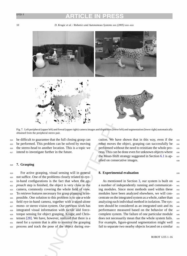
pected, such as in the lower-left image ofFig. 7. We 589
apply a Mean-Shift algorithm, Comaniciu et al.[19] to 590
prune the data, using the fact that the points represent-591
ing the object are located in a relatively small part of 3D592
space and the center of these points is approximately593
known. After applying a sequence of morphological594
operation a mask is found as shown in the lower-right595
image. 596
6 597
ither598
u era.599
W ter600
c ke a601
s , and602
f ould603
h ilable604
f 605
l that606
t ace.607
U n 608
a the609
fi the610
o reo611
v . In612
p ill613
UN
CO
RR
E
he foveal camera image, fitting a plane to the dhus, it is assumed that there is a dominating p
hat can be mapped to the model. The process isher improved searching for straight edges aroundlane. The complete flow from hypotheses gen
ion to pose estimation and tracking is performed futomatic.
. Manipulating unknown objects
For general setting, manipulation of unknownects has rarely been pursued. The primary reasikely to be that the shape of an object has to beermined in order to successfully grasp it. Anotheron is that, even if the location is given by a pointesture, the size also has to be known and the oegmented from its background.
ED
ROBOT 1235 1–1
.2. Approach
Approaching an unknown object can be done esing the stereo-head or with an eye-in-hand camithout knowing the identity of the object the lat
ase is hardly feasible. It would be possible to taequence of images, while approaching the objectrom these estimate a disparity map, but this map wardly be as accurate as using the disparities ava
rom the foveal camera set.If the stereo-head is used instead, it is essentia
he robot gripper itself can be located in disparity spsing the mask derived in Section6.1, the elongationd orientation of the object can be determine andngers of the gripper be placed on either side ofbject. In general we will not be able, from one steiew only, to retrieve the full 3D shape of the objectarticular, if the extension in depth is significant, it w
NC
OR
RE
CTE
D P
RO
OF
ROBOT 1235 1–16
10 D. Kragic et al. / Robotics and Autonomous Systems xxx (2005) xxx–xxx
Fig. 7. Left peripheral (upper left) and foveal (upper right) camera images and disparities (lower left) and segmentation (lower right) automaticallyobtained from the peripheral stereo pair.
be difficult to guarantee that the full closing grasp can614
be performed. This problem can be solved by moving615
the stereo-head to another location. This is a topic we616
intend to investigate further in the future.617
7. Grasping618
For active grasping, visual sensing will in general619
not suffice. One of the problems closely related to eye-620
in-hand configurations is the fact that when theap-621
proachstep is finished, the object is very close to the622
camera, commonly covering the whole field of view.623
To retrieve features necessary for grasp planning is im-624
possible. One solution to this problem is to use a wide625
field eye-in-hand camera, together with a stand-alone626
mono- or stereo vision system. Our previous work has627
integrated visual information with tactile and force-628
torque sensing for object grasping, Kragic and Chris-629
tensen[28]. We have, however, realized that there is a630
need for a system that is able to monitor the grasping631
process and track the pose of the object during exe-632
cution. We have shown that in this way, even if the633
robot moves the object, grasping can successfully be634
performed without the need to reinitiate the whole pro-635
cess. This can be done even for unknown objects where636
the Mean-Shift strategy suggested in Section6.1is ap- 637
plied on consecutive images. 638
8. Experimental evaluation 639
As mentioned in Section3, our system is built on 640
a number of independently running and communicat-641
ing modules. Since most methods used within these642
modules have been analyzed elsewhere, we will con-643
centrate on the integrated system as a whole, rather than644
analyzing each individual method in isolation. The sys-645
tem should be considered as an integrated unit and its646
performance measured based on the behavior of the647
complete system. The failure of one particular module648
does not necessarily mean that the whole system fails.649
For example, figure-ground segmentation might well650
fail to separate two nearby objects located on a similar651
U

CT
PR
OO
F
6
D. Kragic et al. / Robotics and Autonomous Systems xxx (2005) xxx–xxx 11
distance, but the system might still be able to initiate652
pose estimation after recognition.653
The following properties of the system have been654
evaluated, as will be described in more detail in the655
sections below:656
• combined figure-ground segmentation based on bin-657
ocular disparities and monocular pose estimation,658
• combined monocular Cooccurence Color Histog-659
rams (CCH) Chang and Krumm[29] based object660
recognition and monocular pose estimation,661
• robustness of figure-ground segmentation,662
• robustness toward occlusions using SIFT features,663
• robustness of pose initialization toward rotations.664
For recognition, a set of 28 objects was used.665
Fig. 8 shows a few of them. A database was created666
consisting of object models based on SIFT features667
and CCHs. Eight views per object were used for the668
SIFT models as well as in the case of CCHs. Pose esti-669
mation was only considered for the first three box-like670
objects, automatically starting as one of these objects671
are recognized. For this purpose, the width, height and672
thickness of these objects were measured and recorded673
in the database.674
Since the observed matching scores did not signif-675
icantly differ from those already published in Lowe676
[24] and Mikolajczyk and Schmid[30] we have cho-677
sen not to include any additional quantitative results. A678
few observations have lead us to believe that recogni-679
t ing680
u rely681
r lient682
features are due to specularities. However, the distinct683
color makes it particularly suitable for CCHs, which on684
the other hand have a tendency of mixing up the tiger685
and the giraffe, unlike the recognition module based on686
SIFT features. 687
8.1. Binocular segmentation and pose estimation 688
The first experiments illustrate the typical behavior689
of the system with binocular disparity based figure-690
ground segmentation and SIFT based recognition. Re-691
sults from these experiments can be seen inFig. 9. 692
The first column shows the left foveal camera images693
prior to the experiments. It is clear that a requested ob-694
ject would be hard to find, without peripheral vision695
controlling a change in gaze direction. However, from696
the disparity maps in the second column the system is697
able to locate a number of object hypotheses, which698
can be shown as white blobs overlaid on-top of the699
left peripheral camera image in the third column of the700
figure. 701
The matching scores of the recognition module702
for these two examples were 66% and 70%, respec-703
tively, measured as the fraction of SIFT features being704
matched to one particular model. Once an object has705
been recognized, pose estimation is automatically initi-706
ated. This is done using SIFT features from the left and707
right foveal camera images, fitting a plane to the data.708
Thus, it is assumed that there is a dominating plane that709
can be mapped to the model. The process is further im-710
p lane.711
T ing712
d 713
ts use
UN
CO
RR
E
ion would benefit from CCHs and SIFT features besed in conjunction. For example, the blue car is raecognized properly using SIFT, since the most sa
Fig. 8. Some of the objec
ED
ROBOT 1235 1–1
roved searching for straight edges around this phe last two columns show an example of this beone in practice.
d for experimental evaluation.

RE
CTE
D P
RO
OF
6
12 D. Kragic et al. / Robotics and Autonomous Systems xxx (2005) xxx–xxx
Fig. 9. An example of binocular figure-ground segmentation and pose estimation. The first column shows the foveal images before a saccadehas been issued. Disparity maps can be seen in the second column and object hypotheses in third. The last column shows the estimated pose.
8.2. Monocular CCH recognition and pose714
estimation715
Fig. 10 shows two examples of recognition and716
pose estimation based on monocular CCH. Here, object717
recognition and rotation estimation serve as the initial718
values for the model based pose estimation and track-719
ing modules. With the incomplete pose calculated in720
the recognition (first image from the left) and orienta-721
tion estimation step, the initial full pose is estimated722
(second image from the left). After that, a local fitting723
method matches lines in the image with edges of the724
projected object model. The images obtained after con-725
vergence of the tracking scheme is shown on the right.726
It is important to note, that even under the incorrect727
initialization of the two other rotation angles as zero,728
our approach is able to cope with significant deviations729
from this assumption. This is strongly visible in the sec-730
ond example where the angle around camera’sZ-axis 731
is more than 20◦. 732
8.3. Robustness of disparity based figure-ground 733
segmentation 734
As mentioned in Section4, object location hypothe- 735
ses are found slicing up the disparities into a binary map736
of pixels located within a given depth range. There are737
some evident disadvantages associated with such a pro-738
cedure. First of all, an object might be tilted and extend739
beyond this range. This can be seen in the upper left740
image inFig. 11—but it does not occur in the second741
image on the same row. However, since a more accu-742
rate localization is found through the focused attention743
process, a saccade is issued to the approximately same744
location. This is shown in the last two images on the745
upper row.
F t): (i) th er threefi
UN
CO
R
ig. 10. From object recognition to pose estimation, (from leftting iterations, (iv) the estimated pose of the object.
ROBOT 1235 1–1
e output of the recognition, (ii) initial pose estimation, (iii) aft

RE
CTE
D P
RO
OF
6
D. Kragic et al. / Robotics and Autonomous Systems xxx (2005) xxx–xxx 13
Fig. 11. The imperfect segmentation does not effect the final pose estimate of the object. The examples show when: (upper) Only a fraction ofthe object was segmented, and (lower) Two hypotheses are overlapping.
Another challenge occurs if two nearby objects are746
placed at almost the same distance, especially if the747
background lacks sufficient texture. Then the objects748
might merge into a single hypothesis, which is shown749
on the second row ofFig. 11. In our experiments750
this seemed more common when a global disparity751
method Kolmogorov and Zabih[23] was used and is752
the reason why we normally use simple area correla-753
tion. The global optimization methods tend to fill in754
the space between the two objects, falsely assuming755
that rapid changes in disparities are unlikely and thus756
should be suppressed. In practice, it is preferable if757
the textureless area between the objects are left unas-758
signed. The right two images on the last row show759
that pose estimation is still be possible, even when760
hypotheses are merged. Depending on the density of761
foveal features, one of the two objects is automatically762
selected. 763
8.4. Robustness of SIFT based recognition toward 764
occlusions 765
In a cluttered environment, a larger fraction of ob-766
jects are likely to be occluded. These occlusions affect767
most involved processes, in particular those of recog-768
nition and pose estimation. The first two images inFig. 769
12show a scene in which the sugar box is partially oc-770
cluded behind a bottle. In the first case, the recognition771
fails because not enough foveal features are available,772
while successful recognition and pose estimation is773
F bject of ever resulti
UN
CO
R
ig. 12. The system is able to cope with situations where the on incorrect pose estimation (lower center).
ROBOT 1235 1–1
interest is significantly occluded. Too much occlusion can how
OR
RE
CTE
D P
RO
OF
6
14 D. Kragic et al. / Robotics and Autonomous Systems xxx (2005) xxx–xxx
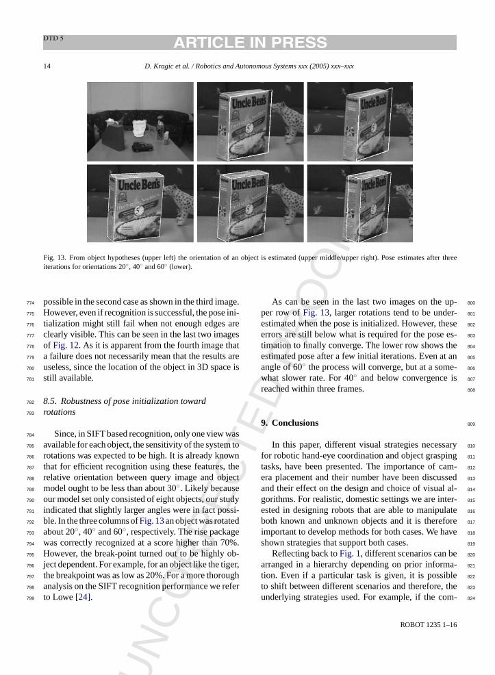
Fig. 13. From object hypotheses (upper left) the orientation of an object is estimated (upper middle/upper right). Pose estimates after threeiterations for orientations 20◦, 40◦ and 60◦ (lower).
possible in the second case as shown in the third image.774
However, even if recognition is successful, the pose ini-775
tialization might still fail when not enough edges are776
clearly visible. This can be seen in the last two images777
of Fig. 12. As it is apparent from the fourth image that778
a failure does not necessarily mean that the results are779
useless, since the location of the object in 3D space is780
still available.781
8.5. Robustness of pose initialization toward782
rotations783
Since, in SIFT based recognition, only one view was784
available for each object, the sensitivity of the system to785
rotations was expected to be high. It is already known786
that for efficient recognition using these features, the787
relative orientation between query image and object788
model ought to be less than about 30◦. Likely because789
our model set only consisted of eight objects, our study790
indicated that slightly larger angles were in fact possi-791
ble. In the three columns ofFig. 13an object was rotated792
about 20◦, 40◦ and 60◦, respectively. The rise package793
was correctly recognized at a score higher than 70%.794
However, the break-point turned out to be highly ob-795
ject dependent. For example, for an object like the tiger,796
the breakpoint was as low as 20%. For a more thorough797
analysis on the SIFT recognition performance we refer798
to Lowe[24].799
As can be seen in the last two images on the up-800
per row ofFig. 13, larger rotations tend to be under-801
estimated when the pose is initialized. However, these802
errors are still below what is required for the pose es-803
timation to finally converge. The lower row shows the804
estimated pose after a few initial iterations. Even at an805
angle of 60◦ the process will converge, but at a some-806
what slower rate. For 40◦ and below convergence is807
reached within three frames. 808
9. Conclusions 809
In this paper, different visual strategies necessary810
for robotic hand-eye coordination and object grasping811
tasks, have been presented. The importance of cam-812
era placement and their number have been discussed813
and their effect on the design and choice of visual al-814
gorithms. For realistic, domestic settings we are inter-815
ested in designing robots that are able to manipulate816
both known and unknown objects and it is therefore817
important to develop methods for both cases. We have818
shown strategies that support both cases. 819
Reflecting back toFig. 1, different scenarios can be820
arranged in a hierarchy depending on prior informa-821
tion. Even if a particular task is given, it is possible822
to shift between different scenarios and therefore, the823
underlying strategies used. For example, if the com-824
UN
C
ROBOT 1235 1–1
CT
PR
OO
F
6
D. Kragic et al. / Robotics and Autonomous Systems xxx (2005) xxx–xxx 15
mand “Pick Up This Cup” is given, but the system fails825
to verify the existence of the cup, the execution may826
still continue as if “Pick up The Cup” was given. A827
vice-versa example is if the command “Pick Up This828
Object” was given and the system realizes that the ob-829
ject is, in fact, a known box of raisins. Then, the sys-830
tem automatically changes the task to “Pick Up The831
Raisins”. In the future, we want to develop a more832
formal description for the above, in order to design833
a visual system framework for robotic manipulation in834
general.835
References836
[1] S. Hutchinson, G. Hager, P. Corke, A tutorial on visual servo837
control, IEEE Trans. Robot. Autom. 12 (5) (1996) 651–670.838
[2] D.H. Ballard, Animate vision, Artif. Intel. 48 (1) (1991) 57–839
86.840
[3] M. Bj orkman, D. Kragic, Combination of foveal and peripheral841
vision for object recognition and pose estimation, Proceedings842
of the IEEE International Conference on Robotics and Automa-843
tion, ICRA’04 5, 2004, pp. 5135–5140.844
[4] S. Kim, I. Kim, I. Kweon, Robust model-based 3d object recog-845
nition by combining feature matching with tracking, Proceed-846
ings of the IEEE International Conference on Robotics and847
Automation, ICRA’03, 2003, pp. 2123–2128.848
[5] E. Malis, G. Chesi, R. Cipolla, 2 1/2 d Visual servoing with849
respect to planar contours having complex and unknown shapes,850
Int. J. Robot. Res. 22 (10–11) (2003) 841–854.851
[6] D. Kragic, H. Christensen, A framework for visual servoing,852
Proceedings of the International Conference on Computer Vi-853
854
ct to855
IEEE856
l. 2,857
858
hin859
Mag.860
861
es-862
nal.863
864
[ e vi-865
and866
ol-867
868
[ ector,869
870
[ digm871
au-872
24,873
874
[ .
[14] H. Longuet-Higgins, The interpretation of a moving retinal im-875
age, Philos. Trans. R. Soc. Lond., B 208 (1980) 385–397. 876
[15] H. Longuet-Higgins, A computer algorithm for reconstructing877
a scene from two projections, Nature 293 (1981) 133–135. 878
[16] S.E. Palmer, Vision Science: Photons to Phenomenology, MIT879
Press, Cambridge, MA, 1999. 880
[17] L. Itti, C. Koch, E. Niebur, A model of saliency-based visual881
attention for rapid scene analysis, IEEE Trans. Pattern Anal.882
Mach. Intel. 20 (11) (1998) 1254–1259. 883
[18] M. Bjorkman, J.-O. Eklundh, Attending, foveating and recog-884
nizing objects in real world scenes, Proceedings of British Ma-885
chine Vision Conference, BMVC’04, 2004. 886
[19] D. Comaniciu, V. Ramesh, P. Meer, Real-time tracking of non-887
rigid objects using mean shift, Proceedings of the IEEE Con-888
ference on Computer Vision and Pattern Recognition, CVPR889
2000, 2000, pp. 142–151. 890
[20] M. Zillich, D. Roobaert, J.O. Eklundh, A pure learning ap-891
proach to background-invariant object recognition using ped-892
agogical support vector learning, CVPR-2001, IEEE, Kauai,893
2001. 894
[21] D. Kragic, Visual servoing for manipulation: robustness and in-895
tegration issues, Ph.D. thesis, Computational Vision and Active896
Perception Laboratory (CVAP), Royal Institute of Technology,897
Stockholm, Sweden, 2001. 898
[22] K. Konolige, Small vision systems: hardware and implemen-899
tation, International Symposium on Robotics Research, 1997,900
pp. 203–212. 901
[23] V. Kolmogorov, R. Zabih, Computing visual correspondence902
with occlusions using graph cuts, Proceedings of the IEEE903
International Conference Computer Vision, 2001, pp. 508–904
515. 905
[24] D.G. Lowe, Object recognition from local scale-invariant fea-906
tures, Proceedings of the IEEE International Conference on907
Computer Vision (ICCV 99), 1999, pp. 1150–1157. 908
[25] S. Ekvall, F. Hoffmann, D. Kragic, Object recognition and pose909
nce910
Con-911
912
ine 913
on-914
pp.915
916
ation917
nal918
02,919
920
odel921
Con-922
pp.923
924
cur-925
Con-926
, pp.927
928
iant929
nfer-930
931
UN
CO
RR
E
sion Systems, ICVS 2003, 2003, pp. 345–354.[7] S. Benhimane, E. Malis, Vision-based control with respe
planar and non-planar objects using a zooming camera,IEEE International Conference on Advanced Robotics, vo2003, pp. 991–996.
[8] S. Vinoski, CORBA: integrating diverser applications witdistributed heterogeneous environments, IEEE Commun.14 (2) (1997).
[9] M. Bj orkman, J.-O. Eklundh, Real-time epipolar geometrytimation of binocular stereo heads, IEEE Trans. Pattern AMach. Intel. 24 (3) (2002) 425–432.
10] M. Bjorkman, Real-time motion and stereo cues for activsual observers, Doctoral dissertation, Computational VisionActive Perception Laboratory (CVAP), Royal Inst. of Technogy, Stockholm, Sweden, 2002.
11] C. Harris, M. Stephens, A combined corner and edge detProc. Alvey Vision Conference, 1988, pp. 147–151.
12] M. Fischler, R. Bolles, Random sample consensus: a parafor model fitting with applications to image analysis andtomated cartography, Communications of the ACM, vol.1981, pp. 381–395.
13] P.J. Huber, Robust Statistics, John Willey and Sons, 1981
ED
ROBOT 1235 1–1
estimation for robotic manipulation using color cooccurrehistograms, Proceedings of the IEEE/RSJ Internationalference Intelligent Robots and Systems, IROS’03, 2003.
[26] D. Kragic, A. Miller, P. Allen, Real-time tracking meets onlgrasp planning, Proceedings of the IEEE International Cference on Robotics and Automation, ICRA’01 3, 2001,2460–2465.
[27] D. Kragic, H. Christensen, Weak models and cue integrfor real-time tracking, Proceedings of the IEEE InternatioConference on Robotics and Automation, ICRA’02 3, 20pp. 3044–3049.
[28] D. Kragic, H. Christensen, Confluence of parameters in mbased tracking, Proceedings of the IEEE Internationalference on Robotics and Automation, ICRA’03 3, 2003a,3485–3490.
[29] P. Chang, J. Krumm, Object recognition with color coocrence histograms, Proceedings of the IEEE Internationalference Computer Vision and Pattern Recognition, 1999498–504.
[30] K. Mikolajczyk, C. Schmid, Indexing based on scale invarinterest points, Proceedings of the IEEE International Coence Computer Vision, ICCV’01, 2001, pp. 525–531.

T P
RO
OF
16 D. Kragic et al. / Robotics and Autonomous Systems xxx (2005) xxx–xxx
Danica Kragic is an assistant professor at the Computational Vision932
and Active Perception Laboratory at the Department of Numerical933
Analysis and Computer Science at the Royal Institute of Technology,934
Stockholm, Sweden. She received the MS degree in mechanical en-935
gineering from the Technical University of Rijeka, Croatia, in 1995936
and PhD degree in computer science from the Royal Institute of Tech-937
nology, Stockholm, Sweden. Her research interest include computer938
vision, learning by demonstration, visual servoing, human-machine939
collaboration and path planning.940
Martenrten Bj orkman received in a PhD in computer vision at941
KTH in Stockholm, Sweden in 2002. Between 1994 and 1997 he942
was employed by Mentor Graphics. He is currently active as a post-943
doc within the EC sponsored project MobVis. His primary research944
interests are stereo vision, cognitive vision systems and image based945
rendering.946
Henrik I.Christensen is a chaired professor of computer science and947
the director of the Centre for Autonomous Systems at the Swedish948
Royal Institute of Technology, Stockholm, Sweden. He is also the co-949
ordinator of the EU network EURON. He does research on systems950
integration, mapping and sensory fusion. He has published more951
than 190 contributions on vision, AI and robotics. He serves on
the editorial board of IJRR, Autonomous Robots, IJPRAI and AI952
Magazine. 953
Jan-Olof Eklundh graduated in mathematics at Stockholm Univer-954
sity, 1970. He then joined the newly formed Laboratory for Image955
Analysis at the National Defence Research Institute, Stockholm, and956
spent 1977-1979 at the Computer Vision Laboratory, University of957
Maryland. In 1982 he became associate professor at KTH where958
he founded the Computer Vision and Active Perception Laboratory,959
CVAP. In 1996 he initiated the Center for Autonomous Systems,960
in which CVAP is now a key partner. 1986 he became professor in961
computer science and in 1995 Dean of the School of Electrical Engi-962
neering and Information Technology at KTH. His research interests963
cover a broad range of topics in computational vision, image pro-964
cessing, and robotics, especially active visual machine perception965
with relations to human vision, analysis of shape and geometry and966
motion, behavioral aspects of perception, and perceptually guided967
autonomous systems. He is and has been on the editorial boards of968
several journals, including IEEE PAMI, IJCV, CVIU and IVC and969
chaired ICCV 1990 and ECCV 1994. Professor Eklundh is a mem-970
ber of the Royal Swedish Academy of Science, the Royal Danish971
Academy of Sciences and Letters and the Royal Swedish Academy972
of Engineering Science. 973
OR
RE
C
UN
C
ED
ROBOT 1235 1–16