visit us at . · the simple mechanical operation of the hydrovoir combined ... check the squareness...
TRANSCRIPT

7350 E. Progress Place • Englewood, CO USA 80111 • Toll Free: 800.525.9930 • Phone: 303.779.1777 • Fax: 303.779.1277
MODEL AF
Hydrovoir Assembly Instructions
VISIT US AT
WWW.WILFLEY.COM

7350 E. Progress Place • Englewood, CO USA 80111 • Toll Free: 800.525.9930 • Phone: 303.779.1777 • Fax: 303.779.1277 1
CENTRIFUGAL
P U M P S
WILFLEY MODEL AF PUMP HYDROVOIR ASSEMBLY INSTRUCTIONS
The Hydrovoir is a revolutionary sealing device that can be fitted to existing Wilfley AF and AG pumps. The Hydrovoir prevents leakage during start-up and shut-down of Wilfley Centrifugal Pumps. The simple mechanical operation of the Hydrovoir combined with the hydraulic sealing action of the Wilfley expeller provides efficient, leak-free pumping of corrosive and abrasive materials. The Hydrovoir is available on all new Wilfley AF and AG centrifugal pumps. Traditional AF and AG pumps can be retrofitted with the Hydrovoir. The retrofit kits are designed to minimize the replacement of standard parts. Gasket kits and parts kits are also available to rebuild your Hydrovoir. See the complete listings of kits and parts on page 28.
7350 E. Progress Place • Englewood, CO USA 80111 • Toll Free: 800.525.9930 • Phone: 303.779.1777 • Fax: 303.779.1277 2
CENTRIFUGAL
P U M P S
HYDROVOIR INSTALLATION AND MAINTENANCE The instructions in this booklet are designed for easy installation and maintenance of your Hydrovoir. These instructions should be used with the Wilfley Model AF Operating Handbook which covers general pump maintenance, operating procedures, safety precautions, and standard parts lists. This booklet is divided into three major sections:
1. Shaft and Frame Modifications- Existing AF shafts and frames will need modifications to accept the Hydrovoir;
2. Hydrovoir Installation - Installing the Hydrovoir into new or modified frames; 3. Hydrovoir Rebuilding - Detailed procedures to keep your Hydrovoir in top
condition. Before you begin working on any Wilfley centrifugal pump, please drain and decontaminate the entire unit. Decontamination is especially important with the Hydrovoir reservoir. Please observe all safety precautions. It is recommended that an anti-seize compound be used on all stainless steel bolt threads to prevent galling. Please replace all gaskets and o-rings if their seal surfaces have been disturbed during maintenance. The impeller provides compression of the front and rear actuator gaskets 95 A and N. If the impeller is removed, the teflon actuator gaskets must be replaced.
7350 E. Progress Place • Englewood, CO USA 80111 • Toll Free: 800.525.9930 • Phone: 303.779.1777 • Fax: 303.779.1277 3
CENTRIFUGAL
P U M P S
Some special tools and lubricants have been included in your Hydrovoir pump kit to assist assembly. They include:
1. The Wilfley Shaft Adjustment Gauge 2. 5/32 'T' handle Allen wrench 3. Synthetic grease 4. Molybdenum grease 5. Anti-seize compound
To complete assembly you will need a standard set of:
1. box end wrenches 2. a parallel bar 3. "C" clamps 4. feeler gauges
A magnetic base dial indicator will be needed to verify the alignment of the shaft and frame. If the Wilfley Shaft Adjustment Gauge is not available, a set of depth micrometers will be needed. The Hydrovoir is manufactured by A. R. Wilfley and Sons, Inc. under Patent #4,915,579 with additional patents pendings. Hydrovoir is a registered trademark of A. R. Wilfley and Sons, Inc. If you have any questions regarding these instructions or the operation of the Hydrovoir, please call a Wilfley Service Engineer at 1-800-525-9930.

7350 E. Progress Place • Englewood, CO USA 80111 • Toll Free: 800.525.9930 • Phone: 303.779.1777 • Fax: 303.779.1277 4
CENTRIFUGAL
P U M P S
MODEL AF HYDROVOIR SHAFT AND FRAME MODIFICATIONS
The Hydrovoir may be fitted to existing AF pumps. Shaft and frame modifications need to be made for the correct alignment of the Hydrovoir. The shaft will be converted from a two-piece sliding unit into a rigid assembly of a specific length. Some parts may need minor machining for compatibility with the Hydrovoir. The hub of the impeller (8) may need to be machined as shown below on this page. Two AF Frame 3 brackets (15), 235-228 and 235-229, will need to be bored out as shown on page 7. All other parts, if they are in good condition, will not need machining modifications. 1. Remove the case (3) from the frame assembly; the case will be used again. 2. Unscrew the impeller (8) from the shaft (13) and remove the rotary seal ring (9)
and gasket (10A); the impeller will be used again. Check the length of the impeller hub. Machine the hub to meet the dimensions listed in the following drawing. Please chase the threaded hole in the hub with a bottom tap.

7350 E. Progress Place • Englewood, CO USA 80111 • Toll Free: 800.525.9930 • Phone: 303.779.1777 • Fax: 303.779.1277 5
CENTRIFUGAL
P U M P S
3. Remove the case plate (5) and case plate hardware from the pump. The case plate labyrinth ring (67), stationary seal ring (11), stationary seal ring housing and gasket (12, 12A), studs, nuts, and washers (12B,C,D) will not be used with the Hydrovoir. The case plate will be used again; 5A and 67A should be replaced. Thoroughly clean the case plate and ensure that the tapped holes are countersunk.
4. Remove the shaft sleeve (14) and gasket (14A); these parts will not be used again. 5. Inspect the bearings. To determine the condition of the bearings, slowly rotate the
shaft; there should be no points of drag, hangup, looseness or ability to wiggle or cock. If bearings need replacement, please refer to bearing assembly instructions in the AF Operating Handbook on pages 6 and 7.
6. Check the shaft runout. Mount the dial indicator on the bracket (15) and sweep the
end of the shaft (13) close to the thread relief. A total indicator reading in excess of .005 inches is cause to replace the shaft.
7350 E. Progress Place • Englewood, CO USA 80111 • Toll Free: 800.525.9930 • Phone: 303.779.1777 • Fax: 303.779.1277 6
CENTRIFUGAL
P U M P S
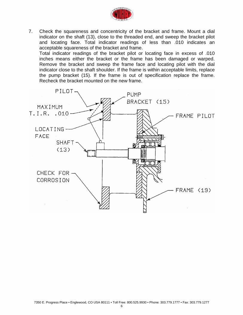
7. Check the squareness and concentricity of the bracket and frame. Mount a dial indicator on the shaft (13), close to the threaded end, and sweep the bracket pilot and locating face. Total indicator readings of less than .010 indicates an acceptable squareness of the bracket and frame. Total indicator readings of the bracket pilot or locating face in excess of .010 inches means either the bracket or the frame has been damaged or warped. Remove the bracket and sweep the frame face and locating pilot with the dial indicator close to the shaft shoulder. If the frame is within acceptable limits, replace the pump bracket (15). If the frame is out of specification replace the frame. Recheck the bracket mounted on the new frame.
7350 E. Progress Place • Englewood, CO USA 80111 • Toll Free: 800.525.9930 • Phone: 303.779.1777 • Fax: 303.779.1277 7
CENTRIFUGAL
P U M P S
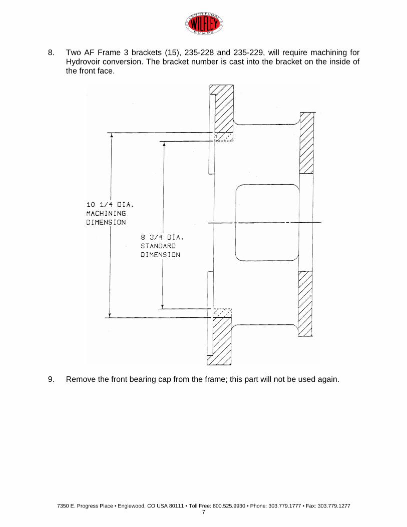
8. Two AF Frame 3 brackets (15), 235-228 and 235-229, will require machining for Hydrovoir conversion. The bracket number is cast into the bracket on the inside of the front face.
9. Remove the front bearing cap from the frame; this part will not be used again.

7350 E. Progress Place • Englewood, CO USA 80111 • Toll Free: 800.525.9930 • Phone: 303.779.1777 • Fax: 303.779.1277 8
CENTRIFUGAL
P U M P S
10. Install the front bearing oil seal (98R) into the new outer front bearing cap (98Q) with the spring side out. The spring side out mounting prevents outside contaminants from entering the frame. Be sure the seal is seated firmly against the bottom bore of the bearing cap and the seal lip is in good condition.
11. Grease the oil seal lip, carefully slide the outer front bearing cap (98Q) onto the shaft and secure to the frame (19) using the bearing cap screws and lockwashers (18B,C). Be very careful not to damage the lip of the seal during assembly.
7350 E. Progress Place • Englewood, CO USA 80111 • Toll Free: 800.525.9930 • Phone: 303.779.1777 • Fax: 303.779.1277 9
CENTRIFUGAL
P U M P S
STEPS 12 THROUGH 19 REFER TO THE ADJUSTMENT OF THE SHAFT. THE SHAFT WILL BE CONVERTED FROM TWO SLIDING PARTS TO ONE CONNECTED ASSEMBLY. THE SHAFT ASSEMBLY MUST BE ADJUSTED TO A SPECIFIC LENGTH USING SPACERS AND SHIMS. THE CRITICAL SHAFT DIMENSION IS BETWEEN THE BRACKET FACE AND THE SHAFT SHOULDER NEXT TO TIIE FRONT BEARING CAP (SEE TABLE A PAGE 13). TO ACHIEVE THE CORRECT SHAFT LENGTH, MEASUREMENTS MAY BE MADE WITH THE WILFLEY SHAFT ADJUSTMENT GAUGE, FEELER GAUGES, AND A PARALLEL BAR. A DEPTH MICROMETER MAY -BE USED IF A WILFLEY SHAFT ADJUSTMENT GAUGE IS UNAVAILABLE. WHEN USING THE WILFLEY SHAFT ADJUSTMENT GAUGE, REFER TO STEPS 12, 13, 14AND 15. WHEN USING A DEPTH MICROMETER REFER TO STEPS 16, 17, 18,AND 19.

7350 E. Progress Place • Englewood, CO USA 80111 • Toll Free: 800.525.9930 • Phone: 303.779.1777 • Fax: 303.779.1277 10
CENTRIFUGAL
P U M P S
SHAFT ADJUSTMENT USING THE WILFLEY SHAFT ADJUSTMENT GAUGE
12. Remove the governor weight cotter pins (29A), governor weight pins (29), and
governor weights (28). Unbolt and remove the governor springs (25), bolts and nuts (25A,B); these will not be reused. Leave the governor sleeve (24) bolted to the shaft.
13. Slide the Shaft Adjustment Gauge onto the shaft. Clamp a parallel bar to the face of the bracket so that it is resting on the shaft. Push the shaft forward until the Shaft Adjustment Gauge touches the parallel bar and the shaft shoulder.

7350 E. Progress Place • Englewood, CO USA 80111 • Toll Free: 800.525.9930 • Phone: 303.779.1777 • Fax: 303.779.1277 11
CENTRIFUGAL
P U M P S
14. Hold the spacer (98N) between the thrust drive sleeve (38) and the governor sleeve (24). Measure the distance remaining between the spacer and the governor sleeve with feeler gauges. Remove the parallel bar. Install shims that equal the thickness of the feeler gauges and spacers to the thrust drive sleeve. Securely tighten the drive bolts (98L) and nuts (98B). Frames 1 and 2 use .585 inch spacers, Frame 3 and 4 use .845 inch spacers. The frame sizes are stamped on the spacers. NOTE: THE STAINLESS STEEL SHIM SET (98M) CONTAINS .005", 010" AND .015" THICK SHIMS.
15. Be sure the shaft is pushed forward and recheck the shaft setting. There should be no more than .005 inches play between the Shaft Adjustment Gauge and the parallel bar.
THIS COMPLETES THE MODIFICATIONS TO THE SHAFT AND FRAME. THE FRAME IS NOW READY TO ACCEPT A HYDROVOIR ASSEMBLY. PLEASE PROCEED TO PAGE 15.
7350 E. Progress Place • Englewood, CO USA 80111 • Toll Free: 800.525.9930 • Phone: 303.779.1777 • Fax: 303.779.1277 12
CENTRIFUGAL
P U M P S
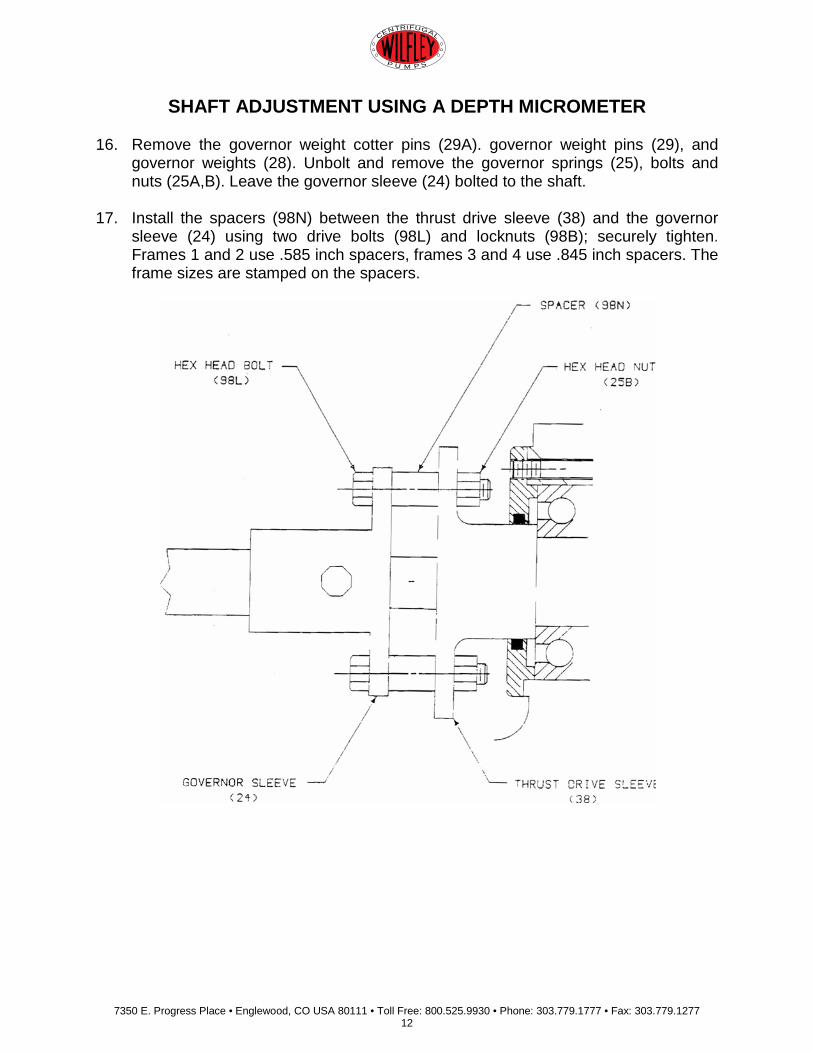
SHAFT ADJUSTMENT USING A DEPTH MICROMETER 16. Remove the governor weight cotter pins (29A). governor weight pins (29), and
governor weights (28). Unbolt and remove the governor springs (25), bolts and nuts (25A,B). Leave the governor sleeve (24) bolted to the shaft.
17. Install the spacers (98N) between the thrust drive sleeve (38) and the governor sleeve (24) using two drive bolts (98L) and locknuts (98B); securely tighten. Frames 1 and 2 use .585 inch spacers, frames 3 and 4 use .845 inch spacers. The frame sizes are stamped on the spacers.

7350 E. Progress Place • Englewood, CO USA 80111 • Toll Free: 800.525.9930 • Phone: 303.779.1777 • Fax: 303.779.1277 13
CENTRIFUGAL
P U M P S
18. To ensure an accurate measurement, the shaft must be pushed as far toward the
front of the pump as possible. Place a parallel bar across the face of the bracket. Use a depth micrometer to measure the distance from the parallel bar to the shoulder directly in front of the outer front bearing cap (98Q). Subtract the dimension noted in Table A from the distance measured. The difference represents the amount of shims (98M) which must be added to each shaft spacer (98N). NOTE: THE STAlNLESS STEEL SHIM SET (98M) CONTAlNS .005", 010"AND .015" THICK SHIMS.
__________ Distance measured from parallel bar to shaft shoulder (Subtract) - __________ Dimension from Table A = Total additional shim thickness required (per spacer)
TABLE A
Frame Size Bracket to Shaft Shoulder 1 3.080 inches 2 3.080 inches 3 3.370 inches 4 3.370 inches
7350 E. Progress Place • Englewood, CO USA 80111 • Toll Free: 800.525.9930 • Phone: 303.779.1777 • Fax: 303.779.1277 14
CENTRIFUGAL
P U M P S
19. Install shims (98M) and spacers (98N). Securely tighten the drive bolts and nuts that connect the governor sleeve and the thrust drive sleeve. Be sure the shaft is pushed forward and recheck the measurement from the bracket face to the shaft shoulder. The length should be within .005 inches of the Table A dimension.
THIS COMPLETES THE MODIFICATIONS TO THE SHAFT AND FRAME. THE FRAME IS NOW READY TO ACCEPT A HYDROVOIR ASSEMBLY.
7350 E. Progress Place • Englewood, CO USA 80111 • Toll Free: 800.525.9930 • Phone: 303.779.1777 • Fax: 303.779.1277 15
CENTRIFUGAL
P U M P S
MODEL AF HYDROVOIR HYDROVOIR INSTALLATION INSTRUCTIONS
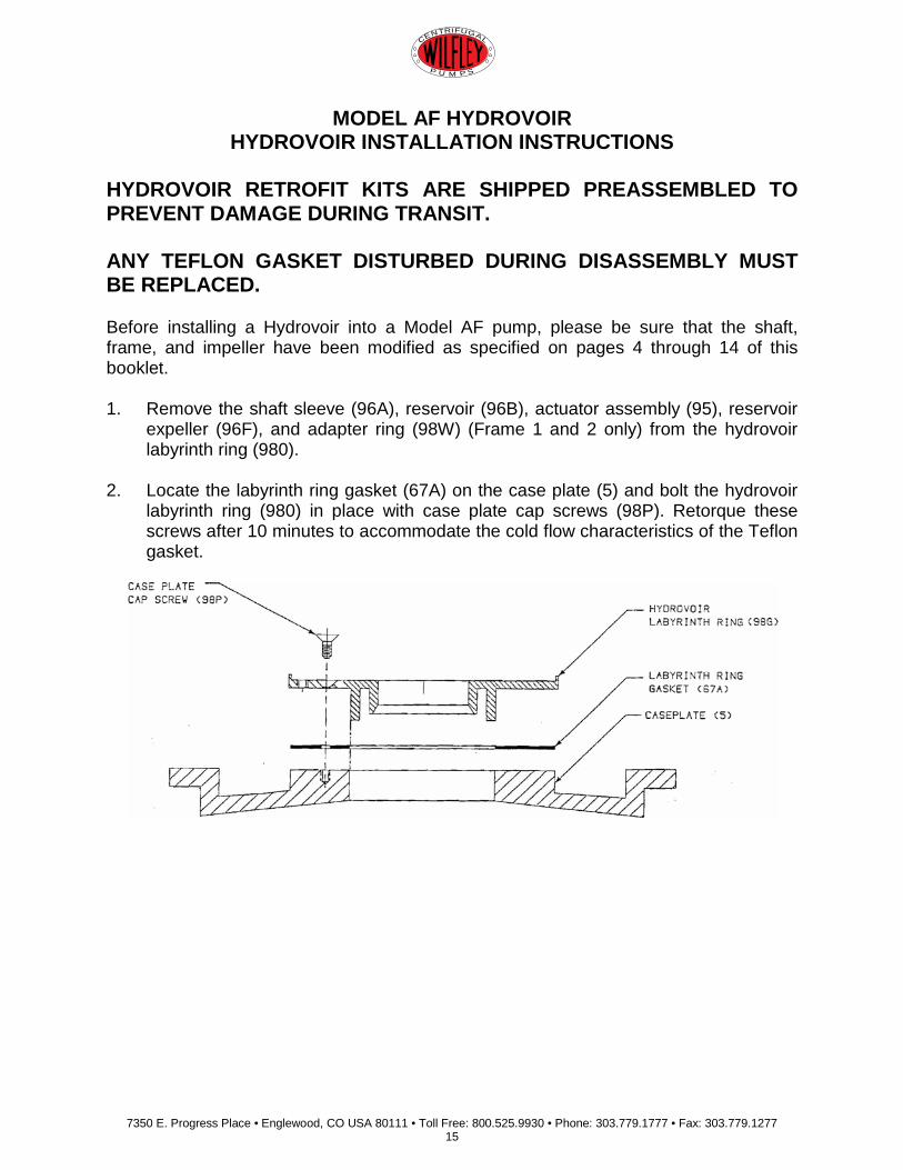
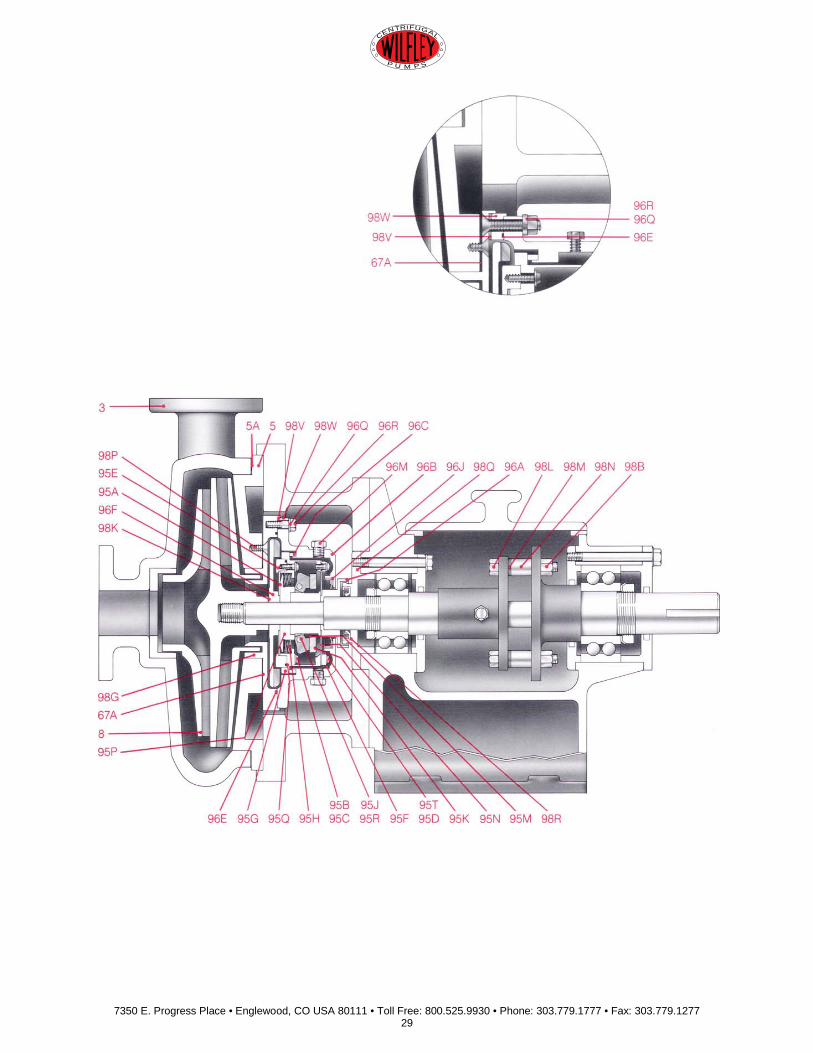
HYDROVOIR RETROFIT KITS ARE SHIPPED PREASSEMBLED TO PREVENT DAMAGE DURING TRANSIT. ANY TEFLON GASKET DISTURBED DURING DISASSEMBLY MUST BE REPLACED. Before installing a Hydrovoir into a Model AF pump, please be sure that the shaft, frame, and impeller have been modified as specified on pages 4 through 14 of this booklet. 1. Remove the shaft sleeve (96A), reservoir (96B), actuator assembly (95), reservoir
expeller (96F), and adapter ring (98W) (Frame 1 and 2 only) from the hydrovoir labyrinth ring (980).
2. Locate the labyrinth ring gasket (67A) on the case plate (5) and bolt the hydrovoir labyrinth ring (980) in place with case plate cap screws (98P). Retorque these screws after 10 minutes to accommodate the cold flow characteristics of the Teflon gasket.
7350 E. Progress Place • Englewood, CO USA 80111 • Toll Free: 800.525.9930 • Phone: 303.779.1777 • Fax: 303.779.1277 16
CENTRIFUGAL
P U M P S
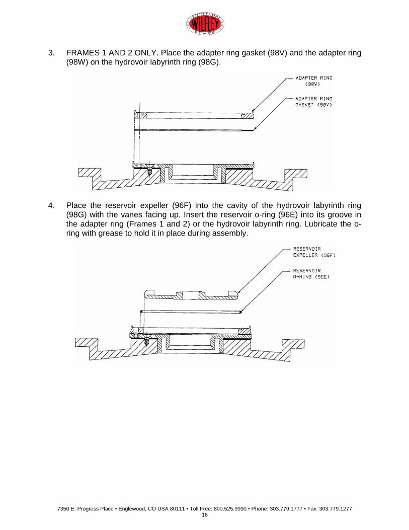
3. FRAMES 1 AND 2 ONLY. Place the adapter ring gasket (98V) and the adapter ring (98W) on the hydrovoir labyrinth ring (98G).
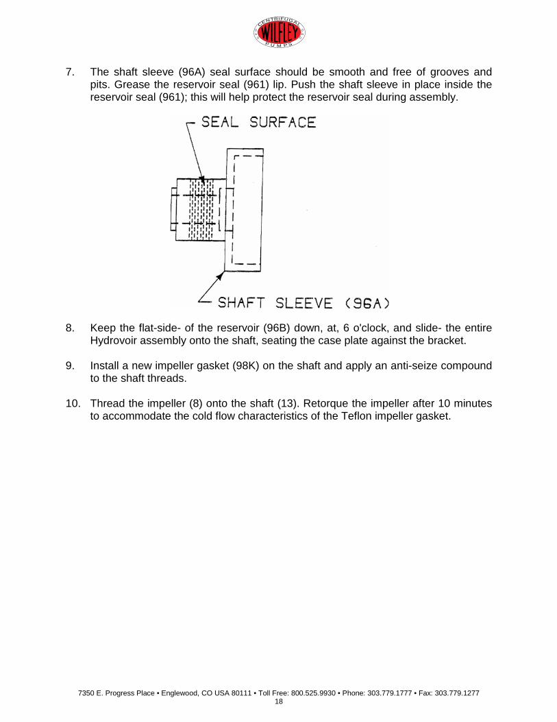
4. Place the reservoir expeller (96F) into the cavity of the hydrovoir labyrinth ring
(98G) with the vanes facing up. Insert the reservoir o-ring (96E) into its groove in the adapter ring (Frames 1 and 2) or the hydrovoir labyrinth ring. Lubricate the o- ring with grease to hold it in place during assembly.

7350 E. Progress Place • Englewood, CO USA 80111 • Toll Free: 800.525.9930 • Phone: 303.779.1777 • Fax: 303.779.1277 17
CENTRIFUGAL
P U M P S
5. Set the actuator assembly (950) onto the hub of the reservoir expeller (96F). The exposed outboard cap screws (95T) should be facing up. ALIGN THE SPRINGS BY PUSHING DOWN ON THE ACTUATOR ASSEMBLY TWICE.
6. Place the reservoir (96B) over the actuator assembly and bolt to the hydrovoir
labyrinth ring (98G). Frame 3 and 4 have an uneven bolt pattern on the reservoir with three holes around the upper half and four in the lower or flat side of the reservoir. Frame 1 and 2 require adapter ring flat washers (98T) underneath the labyrinth lockwashers (96Q).
7350 E. Progress Place • Englewood, CO USA 80111 • Toll Free: 800.525.9930 • Phone: 303.779.1777 • Fax: 303.779.1277 18
CENTRIFUGAL
P U M P S
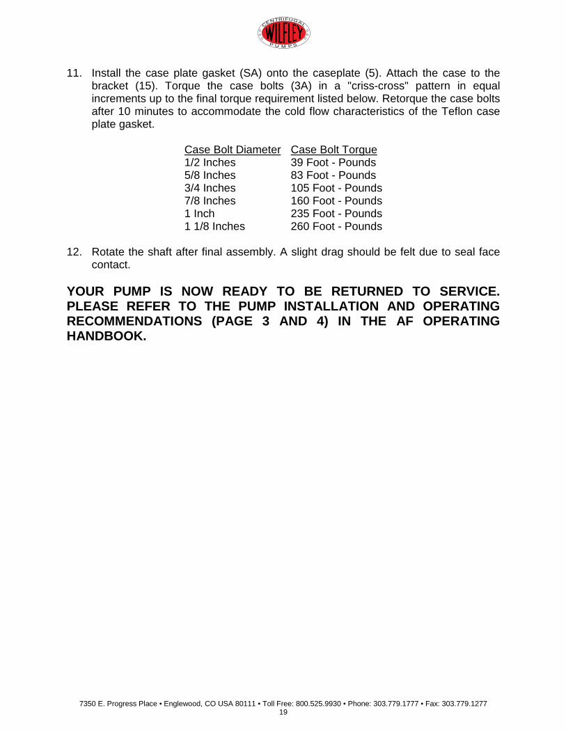
7. The shaft sleeve (96A) seal surface should be smooth and free of grooves and pits. Grease the reservoir seal (961) lip. Push the shaft sleeve in place inside the reservoir seal (961); this will help protect the reservoir seal during assembly.
8. Keep the flat-side- of the reservoir (96B) down, at, 6 o'clock, and slide- the entire
Hydrovoir assembly onto the shaft, seating the case plate against the bracket.
9. Install a new impeller gasket (98K) on the shaft and apply an anti-seize compound to the shaft threads.
10. Thread the impeller (8) onto the shaft (13). Retorque the impeller after 10 minutes to accommodate the cold flow characteristics of the Teflon impeller gasket.
7350 E. Progress Place • Englewood, CO USA 80111 • Toll Free: 800.525.9930 • Phone: 303.779.1777 • Fax: 303.779.1277 19
CENTRIFUGAL
P U M P S
11. Install the case plate gasket (SA) onto the caseplate (5). Attach the case to the bracket (15). Torque the case bolts (3A) in a "criss-cross" pattern in equal increments up to the final torque requirement listed below. Retorque the case bolts after 10 minutes to accommodate the cold flow characteristics of the Teflon case plate gasket.
Case Bolt Diameter Case Bolt Torgue 1/2 Inches 39 Foot - Pounds 5/8 Inches 83 Foot - Pounds 3/4 Inches 105 Foot - Pounds 7/8 Inches 160 Foot - Pounds 1 Inch 235 Foot - Pounds 1 1/8 Inches 260 Foot - Pounds
12. Rotate the shaft after final assembly. A slight drag should be felt due to seal face
contact. YOUR PUMP IS NOW READY TO BE RETURNED TO SERVICE. PLEASE REFER TO THE PUMP INSTALLATION AND OPERATING RECOMMENDATIONS (PAGE 3 AND 4) IN THE AF OPERATING HANDBOOK.
7350 E. Progress Place • Englewood, CO USA 80111 • Toll Free: 800.525.9930 • Phone: 303.779.1777 • Fax: 303.779.1277 20
CENTRIFUGAL
P U M P S
MODEL AF HYDROVOIR HYDROVOIR REBUILDING INSTRUCTIONS
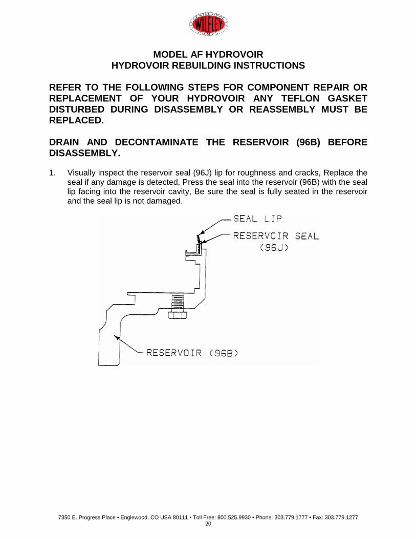
REFER TO THE FOLLOWING STEPS FOR COMPONENT REPAIR OR REPLACEMENT OF YOUR HYDROVOIR ANY TEFLON GASKET DISTURBED DURING DISASSEMBLY OR REASSEMBLY MUST BE REPLACED. DRAIN AND DECONTAMINATE THE RESERVOIR (96B) BEFORE DISASSEMBLY. 1. Visually inspect the reservoir seal (96J) lip for roughness and cracks, Replace the
seal if any damage is detected, Press the seal into the reservoir (96B) with the seal lip facing into the reservoir cavity, Be sure the seal is fully seated in the reservoir and the seal lip is not damaged.
7350 E. Progress Place • Englewood, CO USA 80111 • Toll Free: 800.525.9930 • Phone: 303.779.1777 • Fax: 303.779.1277 21
CENTRIFUGAL
P U M P S
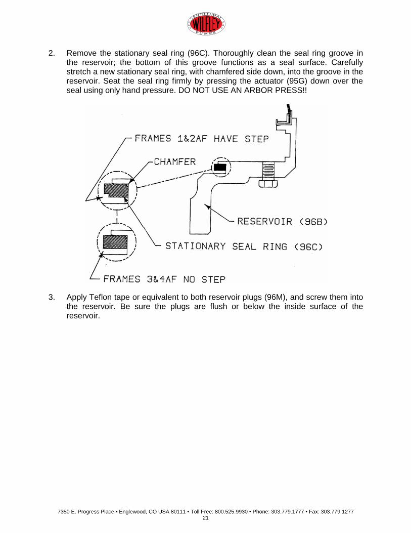
2. Remove the stationary seal ring (96C). Thoroughly clean the seal ring groove in the reservoir; the bottom of this groove functions as a seal surface. Carefully stretch a new stationary seal ring, with chamfered side down, into the groove in the reservoir. Seat the seal ring firmly by pressing the actuator (95G) down over the seal using only hand pressure. DO NOT USE AN ARBOR PRESS!!
3. Apply Teflon tape or equivalent to both reservoir plugs (96M), and screw them into
the reservoir. Be sure the plugs are flush or below the inside surface of the reservoir.

7350 E. Progress Place • Englewood, CO USA 80111 • Toll Free: 800.525.9930 • Phone: 303.779.1777 • Fax: 303.779.1277 22
CENTRIFUGAL
P U M P S
4. Visually inspect the actuator (95G) seal surface for scratches, uneven wear, areas of non-contact, or product buildup. Any defects are cause to repair or replace the actuator. The seal surface may be machined to maintain a minimum dimension shown in the following drawing. A smooth, flat, surface within .0005 inches is critical for proper sealing.

7350 E. Progress Place • Englewood, CO USA 80111 • Toll Free: 800.525.9930 • Phone: 303.779.1777 • Fax: 303.779.1277 23
CENTRIFUGAL
P U M P S
5. Inspect the spring guide (95P) pilot to ensure a smooth surface; replace if necessary. Inspect the inside diameter of the actuator springs (95H). The entire spring set must be replaced if damage is found on any spring disc. Apply molybdenum-based high pressure grease to both sides of each actuator spring (95H). Stack spring discs, alternating spring bends, on the spring guide (95P) as shown below. It is important that the outside edge of the first spring be in contact with the outside edge of the spring guide.

7350 E. Progress Place • Englewood, CO USA 80111 • Toll Free: 800.525.9930 • Phone: 303.779.1777 • Fax: 303.779.1277 24
CENTRIFUGAL
P U M P S
6. Check the gasket and o-ring surfaces of the inboard lock ring (95E); they should be smooth and free of nicks. Place the inboard lock ring on a table with the threaded holes facing up. Insert the inboard lock ring o-ring (950) into the groove in the lock ring. Install the front actuator gasket (95A) into its recess in the lock ring. Center the spring guide and springs on top of the gasket.
7350 E. Progress Place • Englewood, CO USA 80111 • Toll Free: 800.525.9930 • Phone: 303.779.1777 • Fax: 303.779.1277 25
CENTRIFUGAL
P U M P S
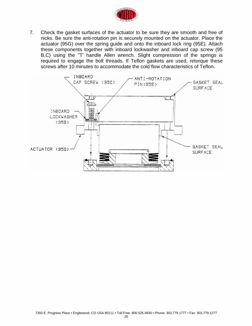
7. Check the gasket surfaces of the actuator to be sure they are smooth and free of nicks. Be sure the anti-rotation pin is securely mounted on the actuator. Place the actuator (95G) over the spring guide and onto the inboard lock ring (95E). Attach these components together with inboard lockwasher and inboard cap screw (95 B,C) using the "T' handle Allen wrench. Slight compression of the springs is required to engage the bolt threads. If Teflon gaskets are used, retorque these screws after 10 minutes to accommodate the cold flow characteristics of Teflon.
7350 E. Progress Place • Englewood, CO USA 80111 • Toll Free: 800.525.9930 • Phone: 303.779.1777 • Fax: 303.779.1277 26
CENTRIFUGAL
P U M P S
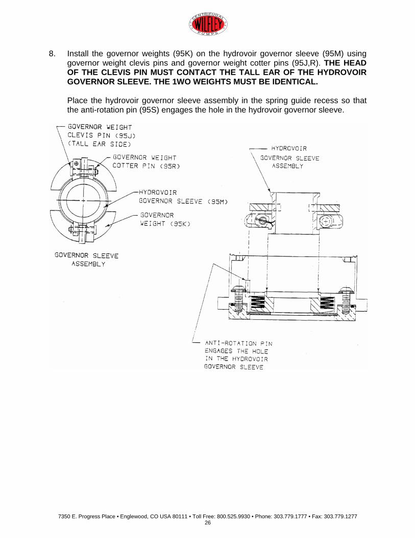
8. Install the governor weights (95K) on the hydrovoir governor sleeve (95M) using governor weight clevis pins and governor weight cotter pins (95J,R). THE HEAD OF THE CLEVIS PIN MUST CONTACT THE TALL EAR OF THE HYDROVOIR GOVERNOR SLEEVE. THE 1WO WEIGHTS MUST BE IDENTICAL.
Place the hydrovoir governor sleeve assembly in the spring guide recess so that the anti-rotation pin (95S) engages the hole in the hydrovoir governor sleeve.
7350 E. Progress Place • Englewood, CO USA 80111 • Toll Free: 800.525.9930 • Phone: 303.779.1777 • Fax: 303.779.1277 27
CENTRIFUGAL
P U M P S
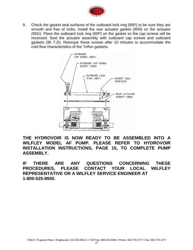
9. Check the gasket seal surfaces of the outboard lock ring (95P) to be sure they are smooth and free of nicks. Install the rear actuator gasket (95N) on the actuator (95G). Place the outboard lock ring (95P) on the gasket so the cap screws will be recessed. Seal the actuator assembly with outboard cap screws and outboard gaskets (95 T,D). Retorque these screws after 10 minutes to accommodate the cold flow characteristics of the Teflon gaskets.
THE HYDROVOIR IS NOW READY TO BE ASSEMBLED INTO A WILFLEY MODEL AF PUMP. PLEASE REFER TO HYDROVOIR INSTALLATION INSTRUCTIONS, PAGE 15, TO COMPLETE PUMP ASSEMBLY. IF THERE ARE ANY QUESTIONS CONCERNING THESE PROCEDURES, PLEASE CONTACT YOUR LOCAL WILFLEY REPRESENTATIVE OR A WILFLEY SERVICE ENGINEER AT 1-800-525-9930.
7350 E. Progress Place • Englewood, CO USA 80111 • Toll Free: 800.525.9930 • Phone: 303.779.1777 • Fax: 303.779.1277 28
CENTRIFUGAL
P U M P S
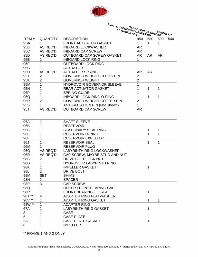
ITEM # QUANTITY DESCRIPTION 950 580 590 540 9SA 1 FRONT ACTUATOR GASKET 1 1 1 95B AS REQ'D INBOARD LOCKWASHER AR 95C AS REQ'D INBOARD CAP SCREW AR 95D AS REQ'D OUTBOARD CAP SCREW GASKET AR AR AR 95E 1 INBOARD LOCK RING 1 95F 1 OUTBOARD LOCK RING 1 95G 1 ACTUATOR 1 95H AS REQ'D ACTUATOR SPRING AR AR 95J 2 GOVERNOR WEIGHT CLEVIS PIN 2 95K 2 GOVERNOR WEIGHT 2 95M 1 HYDROVOIR GOVERNOR SLEEVE 1 95N 1 REAR ACTUATOR GASKET 1 1 1 95P 1 SPRING GUIDE 1 95Q 1 INBOARD LOCK RING O-RING 1 1 1 95R 2 GOVERNOR WEIGHT COTTER PIN 2 95S 1 ANTI-ROTATION PIN (Not Shown) 1 95T AS REQ'D OUTBOARD CAP SCREW AR 96A 1 SHAFT SLEEVE 96B 1 RESERVOIR 96C 1 STATIONARY SEAL RING 1 1 96E 1 RESERVOIR O-RING 1 1 96F 1 RESERVOIR EXPELLER 96J 1 RESERVOIR SEAL 1 1 96M 2 RESERVOIR PLUG 96Q AS REQ'D LABYRINTH RING LOCKWASHER 96R AS REQ'D CAP SCREW, MAYBE STUD AND NUT 98B 2 DRIVE BOLT LOCK NUT 98G 1 HYDROVOIR LABYRINTH RING 98K 1 IMPELLER GASKET 1 98L 2 DRIVE BOLT 98M SET SHIMS 98N 2 SPACER 98P 3 CAP SCREW 98Q 1 OUTER FRONT BEARING CAP 98R 1 FRONT BEARING OIL SEAL 1 98T ** 4 ADAPTER RING FLATWASHER 98V ** 1 ADAPTER RING GASKET 1 1 98W ** 1 ADAPTER RING 67A 1 LABYRINTH RING GASKET 1 3 1 CASE 5 1 CASE PLATE 5A 1 CASE PLATE GASKET 1 8 1 IMPELLER ** FRAME 1 AND 2 ONLY
7350 E. Progress Place • Englewood, CO USA 80111 • Toll Free: 800.525.9930 • Phone: 303.779.1777 • Fax: 303.779.1277 29
CENTRIFUGAL
P U M P S
7350 E. Progress Place • Englewood, CO USA 80111 • Toll Free: 800.525.9930 • Phone: 303.779.1777 • Fax: 303.779.1277 30
CENTRIFUGAL
P U M P S
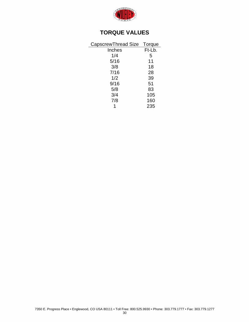
TORQUE VALUES
CapscrewThread Size Torque Inches Ft-Lb.
1/4 5 5/16 11 3/8 18
7/16 28 1/2 39
9/16 51 5/8 83 3/4 105 7/8 160 1 235